WO2017043601A1 - ステータコア、ステータコアを備えたモータ、これに用いられる電磁鋼板片及びその製造方法 - Google Patents
ステータコア、ステータコアを備えたモータ、これに用いられる電磁鋼板片及びその製造方法 Download PDFInfo
- Publication number
- WO2017043601A1 WO2017043601A1 PCT/JP2016/076512 JP2016076512W WO2017043601A1 WO 2017043601 A1 WO2017043601 A1 WO 2017043601A1 JP 2016076512 W JP2016076512 W JP 2016076512W WO 2017043601 A1 WO2017043601 A1 WO 2017043601A1
- Authority
- WO
- WIPO (PCT)
- Prior art keywords
- stator core
- steel plate
- silicon concentration
- steel sheet
- electromagnetic steel
- Prior art date
- Legal status (The legal status is an assumption and is not a legal conclusion. Google has not performed a legal analysis and makes no representation as to the accuracy of the status listed.)
- Ceased
Links
Images






Classifications
-
- C—CHEMISTRY; METALLURGY
- C22—METALLURGY; FERROUS OR NON-FERROUS ALLOYS; TREATMENT OF ALLOYS OR NON-FERROUS METALS
- C22C—ALLOYS
- C22C38/00—Ferrous alloys, e.g. steel alloys
-
- H—ELECTRICITY
- H01—ELECTRIC ELEMENTS
- H01F—MAGNETS; INDUCTANCES; TRANSFORMERS; SELECTION OF MATERIALS FOR THEIR MAGNETIC PROPERTIES
- H01F1/00—Magnets or magnetic bodies characterised by the magnetic materials therefor; Selection of materials for their magnetic properties
- H01F1/01—Magnets or magnetic bodies characterised by the magnetic materials therefor; Selection of materials for their magnetic properties of inorganic materials
- H01F1/03—Magnets or magnetic bodies characterised by the magnetic materials therefor; Selection of materials for their magnetic properties of inorganic materials characterised by their coercivity
- H01F1/12—Magnets or magnetic bodies characterised by the magnetic materials therefor; Selection of materials for their magnetic properties of inorganic materials characterised by their coercivity of soft-magnetic materials
- H01F1/14—Magnets or magnetic bodies characterised by the magnetic materials therefor; Selection of materials for their magnetic properties of inorganic materials characterised by their coercivity of soft-magnetic materials metals or alloys
- H01F1/16—Magnets or magnetic bodies characterised by the magnetic materials therefor; Selection of materials for their magnetic properties of inorganic materials characterised by their coercivity of soft-magnetic materials metals or alloys in the form of sheets
-
- H—ELECTRICITY
- H02—GENERATION; CONVERSION OR DISTRIBUTION OF ELECTRIC POWER
- H02K—DYNAMO-ELECTRIC MACHINES
- H02K1/00—Details of the magnetic circuit
- H02K1/02—Details of the magnetic circuit characterised by the magnetic material
-
- H—ELECTRICITY
- H02—GENERATION; CONVERSION OR DISTRIBUTION OF ELECTRIC POWER
- H02K—DYNAMO-ELECTRIC MACHINES
- H02K1/00—Details of the magnetic circuit
- H02K1/06—Details of the magnetic circuit characterised by the shape, form or construction
- H02K1/12—Stationary parts of the magnetic circuit
- H02K1/18—Means for mounting or fastening magnetic stationary parts on to, or to, the stator structures
-
- H—ELECTRICITY
- H02—GENERATION; CONVERSION OR DISTRIBUTION OF ELECTRIC POWER
- H02K—DYNAMO-ELECTRIC MACHINES
- H02K15/00—Processes or apparatus specially adapted for manufacturing, assembling, maintaining or repairing of dynamo-electric machines
- H02K15/02—Processes or apparatus specially adapted for manufacturing, assembling, maintaining or repairing of dynamo-electric machines of stator or rotor bodies
Definitions
- the present invention relates to a stator core and a motor including the stator core.
- the present invention also relates to an electromagnetic steel sheet piece used for a stator core and a method for manufacturing the same.
- Patent Document 1 proposes an electrical steel sheet having different silicon concentrations in the surface layer portion and the inner layer portion as a motor core material.
- the use of the above-described electrical steel sheet to which high-concentration silicon is added may cause a reduction in torque due to the low saturation magnetic flux density, thereby realizing higher torque and higher output of the motor. Further study was necessary.
- the present invention solves the above-described problems, and an object thereof is to provide a stator core capable of increasing the torque and output of a motor, and a motor including the stator core.
- Another object of the present invention is to provide an electromagnetic steel sheet piece used for a stator core capable of increasing the torque and output of a motor and a method for manufacturing the same.
- an electromagnetic steel sheet piece used for a stator core of a motor comprising a yoke part constituting part and a tooth part constituting part which are integrally formed, wherein the silicon concentration in the surface part of a part of the region is An electrical steel sheet piece having a silicon concentration higher than the silicon concentration in the surface portion of the other region is provided.
- the partial area may be the yoke portion constituting portion.
- the silicon concentration of the partial region or the yoke portion constituting portion may be 3.5 wt% to 6.5 wt%.
- the silicon concentration of the other region or the tooth portion constituting portion may be less than 3.5% by weight.
- the part of the region or the yoke part constituting part may be formed by applying a coating agent containing silicon to a pressed steel sheet and heating.
- a stator core for a motor configured by joining a plurality of laminated bodies formed by laminating a plurality of electromagnetic steel plate pieces in the axial direction and arranging them in an annular arrangement.
- each electromagnetic steel sheet piece includes a yoke part constituting part and a tooth part constituting part integrally formed, and the silicon concentration in the surface part of the partial region of the electromagnetic steel sheet piece is the silicon concentration of the surface part of the other region.
- the stator core is provided.
- the partial area may be the yoke portion constituting portion.
- the silicon concentration in the partial region or the yoke portion constituting portion may be 3.5 wt% to 6.5 wt%.
- the silicon concentration in the other region or the tooth portion constituting portion may be less than 3.5% by weight.
- the partial region or the yoke portion constituting portion may be formed by applying a silicon-containing coating agent to a pressed steel sheet and heating.
- a stator core of a motor configured by laminating a plurality of annular electromagnetic steel plate pieces in the axial direction, the electromagnetic steel plate pieces including a yoke portion constituting portion and a teeth portion constituting portion.
- a stator core in which a silicon concentration in a surface portion of a partial region of the electromagnetic steel sheet piece is higher than a silicon concentration of a surface portion of another region.
- the partial area may be the yoke portion constituting portion.
- the silicon concentration in the partial region or the yoke portion constituting portion may be 3.5 wt% to 6.5 wt%.
- the silicon concentration in the other region or the tooth portion constituting portion may be less than 3.5% by weight.
- the partial region or the yoke portion constituting portion may be formed by applying a silicon-containing coating agent to a pressed steel sheet and heating.
- a motor including any one of the stator cores described above.
- a stator core of a motor including pressing a steel plate to produce a steel plate piece, applying a coating agent containing silicon to a partial region of the steel plate piece, and heating.
- the manufacturing method of the electromagnetic steel plate piece used for is provided.
- the steel plate piece may include a yoke portion constituting portion and a tooth portion constituting portion, and the partial area may be the yoke portion constituting portion.
- the coating agent may include a carburizing agent.
- the silicon concentration in the partial region or the yoke portion constituting portion may be 3.5 wt% to 6.5 wt%.
- the silicon concentration in the other region or the tooth portion constituting portion may be less than 3.5% by weight.
- a magnetic steel sheet piece used for a stator core capable of increasing the torque and output of a motor, and a manufacturing method thereof.
- a stator core that can increase the torque and output of the motor, and a motor including the stator core.
- FIG. 2 It is the schematic which shows the stator core of the motor which concerns on one Embodiment of this invention. It is a top view which shows an example of the electromagnetic steel plate piece which concerns on one Embodiment of this invention. It is the schematic which shows the state which laminated
- the present inventors have found that the magnetic flux density in the stator core when the motor is driven, stress loading due to press fitting, shrink fitting, caulking, etc. during the motor assembly (especially the magnetic flux). It has been found that the magnetic flux density of the entire stator core can be increased and the iron loss can be reduced by selectively siliciding a part of the steel plate pieces constituting the stator core in consideration of the compressive stress parallel to the flow direction). It was.
- an electromagnetic steel plate piece used for a stator core according to an embodiment of the present invention and a manufacturing method thereof, a stator core configured using the electromagnetic steel plate piece, and a motor including the stator core will be described with reference to the drawings.
- the present invention can be implemented in many different modes and should not be construed as being limited to the description of the embodiments described below.
- the same portions or portions having similar functions are denoted by the same reference numerals, and repeated description thereof is omitted.
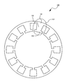
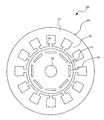
- FIG. 1 is a schematic view showing a stator core 100 of a motor according to an embodiment of the present invention.
- the stator core 100 includes an annular yoke portion 101 and a teeth portion 103 that protrudes radially inward on the inner periphery of the yoke portion 101.
- the stator core 100 may be provided with a flange portion 105 that faces a coil (not shown) wound around the tooth portion 103 and is provided along the circumferential direction (rotational direction of the rotor) at the tip of the tooth portion 103.
- the stator core 100 may be configured by using an electromagnetic steel plate piece 107 produced by subjecting a steel plate piece formed by punching a steel plate into a predetermined shape by press working to a siliconization treatment.
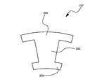
- FIG. 2 is a top view showing an example of the electromagnetic steel plate piece 107 according to the embodiment of the present invention, which constitutes the stator core 100
- FIG. 3 shows the electromagnetic steel plate piece 107 shown in FIG. 2 perpendicular to the circumferential direction. It is the schematic which shows the laminated body formed by laminating
- the electromagnetic steel plate piece 107 has a substantially T-shape and includes a yoke portion constituting portion 201 and a teeth portion constituting portion 203.
- the yoke part constituting part 201 and the teeth part constituting part 203 are formed integrally with each other.
- the electromagnetic steel plate piece 107 may be provided with a collar part constituting part 205.
- the stator core 100 is formed by laminating a plurality of electromagnetic steel plate pieces 107 as shown in FIG. 2 in the axial direction to produce a laminate as shown in FIG. 3, and joining the plurality of laminates in the circumferential direction to form an annular shape. You may comprise by arrange
- a plurality of electromagnetic steel plate pieces 107 are laminated in the rotation axis direction to produce a laminated body, and the laminated body is arranged so as to form an annular shape in the circumferential direction, whereby the yoke part constituting unit 201 has the stator core 100 shown in FIG.
- the tooth portion constituting portion 203 constitutes the teeth portion 103, and the collar portion constituting portion 205 constitutes the flange portion 105.
- FIG. 4 is a schematic diagram showing a state in which electromagnetic steel plate pieces 107a having shapes different from those of the electromagnetic steel plate pieces 107 shown in FIG. 2 are stacked in the axial direction.
- the electromagnetic steel plate piece 107a has an annular shape, and includes an annular yoke portion constituting portion 401 and a teeth portion constituting portion 403 projecting radially inward on the inner periphery of the yoke portion constituting portion 401.
- the electromagnetic steel plate piece 107a may be provided with a flange portion forming portion 405 provided along the circumferential direction (rotating direction of the rotor) at the tip of the tooth portion forming portion 403.
- the stator core 100 may be configured by laminating electromagnetic steel plate pieces 107a having an annular shape as shown in FIG. 4 in the axial direction.
- the magnetic flux density varies in the stator core depending on the portion of the stator core.
- the magnetic flux density is relatively low at the yoke portion of the stator core, and is relatively high at the tooth portion. Therefore, in the stator core 100 of the present invention, by selectively performing a siliconizing process on a partial region of the stator core, the silicon concentration in the partial region is made higher than the silicon concentration in the other region of the stator core, It is characterized in that the magnetic flux density of the entire stator core 100 is increased.
- the stator core 100 is composed of electromagnetic steel plate pieces as illustrated in FIGS.
- the electromagnetic steel plate piece is obtained by subjecting the steel plate piece to a siliconization treatment.
- the electromagnetic steel plate piece according to the present invention the electromagnetic steel plate piece is obtained by selectively performing a siliconization treatment on a partial region of the steel plate piece.
- the silicon concentration in a part of the region is made higher than the silicon concentration in the other region of the electrical steel sheet piece. That is, the silicon concentration of the surface portion of at least a part of the electromagnetic steel sheet piece that has been subjected to the siliconization treatment is higher than the silicon concentration of the surface portion of the other region that has not been subjected to the siliconization treatment.
- the siliconization treatment in the thickness direction of the electromagnetic steel sheet piece may extend over the entire area in the thickness direction of the electromagnetic steel sheet piece, or may be only a partial region in the thickness direction of the electromagnetic steel sheet piece.
- the steel plate piece may be subjected to siliconization treatment from both sides, and the entire plate thickness direction of the steel plate piece may be subjected to siliconization treatment, or both sides of the steel plate piece excluding the intermediate portion in the plate thickness direction of the steel plate piece. Only the siliconizing treatment may be performed to a predetermined depth. Moreover, it is good also as a part which performs a siliconization process from the one surface of a steel plate piece, and does not perform a siliconization process on the other surface.
- the silicon concentration of the yoke portion 101 where the magnetic flux density is relatively low may be higher than the silicon concentration of the tooth portion 103.
- the silicon concentration of the yoke portion 101 By relatively increasing the silicon concentration of the yoke portion 101, the magnetic flux density of the yoke portion 101 when the motor is driven increases.
- the silicon concentration of the yoke part 101 becomes high, the iron loss of the stator core 100 is reduced. Therefore, it is possible to increase the torque and output of the motor using the stator core 100 according to the embodiment of the present invention.
- the silicon concentration in the yoke part 101 is preferably 3.5 wt% or more and 6.5 wt% or less. Further, the silicon concentration in the tooth portion 103 only needs to be lower than the silicon concentration in the yoke portion 101. Since the tooth portion 103 has a relatively high magnetic flux density when the motor is driven, the saturation magnetic flux density of the tooth portion 103 decreases when the tooth portion 103 contains a large amount of silicon. Therefore, it is preferable that the silicon concentration of the tooth portion 103 is 0% by weight or more and less than 3.5% by weight in consideration of silicon diffusion in the siliconization process.
- the silicon concentrations of the yoke part constituting parts 201 and 401 in the electromagnetic steel plate pieces 107 and 107a constituting the yoke part 101 of the stator 100 are the same as those of the tooth part constituting parts 203 and 403.
- the steel plate piece is selectively subjected to siliconization so as to be higher than the silicon concentration. Therefore, in the electromagnetic steel sheet pieces 107 and 107a, the silicon concentration of the surface portions of the yoke portion constituting portions 201 and 401 subjected to the siliconizing treatment is the surface portion of the teeth portion constituting portions 203 and 403 not subjected to the siliconizing treatment. Higher than the silicon concentration.
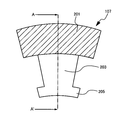
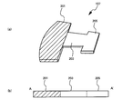
- FIG. 5 is a top view of the electromagnetic steel plate piece 107 according to the embodiment of the present invention shown in FIG. 6A is a perspective view of the electromagnetic steel plate piece 107 shown in FIG. 5, and FIG. 6B is a cross-sectional view of the electromagnetic steel plate piece 107 shown in FIG. 5 along the line AA ′. is there.
- the hatched region is a region having a relatively higher silicon concentration than the other regions.
- the silicon concentration of the yoke part constituting part 201 is changed to other regions (the teeth part constituting part 203 and the iron part constituting part 203).
- the steel plate is selectively subjected to a siliconizing treatment so as to be higher than the silicon concentration of the part constituting part 205).
- the silicon concentration in the surface portion of the yoke portion constituting portion 201 that has been subjected to the siliconizing treatment is higher than the silicon concentration in the surface portions of the tooth portion constituting portion 203 and the flange portion constituting portion 205 that has not been subjected to the siliconizing treatment.
- the silicon concentration in the yoke constituent parts 201 and 401 is preferably 3.5 wt% or more and 6.5 wt% or less. Further, the silicon concentration in the tooth portion constituting portions 203 and 403 should be lower than the silicon concentration in the yoke portion constituting portions 201 and 401, and in consideration of silicon diffusion in the siliconizing process of the yoke portion constituting portions 201 and 401.
- the content is preferably 0% by weight or more and less than 3.5% by weight.
- the silicon concentration in a part of the electromagnetic steel plate pieces 107 and 107a constituting the stator core 100 is set higher than the silicon concentration in the other region of the electromagnetic steel plate pieces 107 and 107a.
- a part of the steel plate is selectively subjected to a siliconizing treatment. As a result, the silicon concentration in the surface portion of some regions of the stator core 100 is higher than the silicon concentration in the surface portion of other regions of the stator core 100.
- the siliconization treatment is performed so that the silicon concentration in the yoke portion constituting portions 201 and 401 constituting the yoke portion 101 having a relatively low magnetic flux density when the motor is driven is higher than the silicon concentration in other regions. May be performed.
- the magnetic flux density of the yoke part 101 at the time of motor drive becomes high. Therefore, the magnetic flux density of the stator core 100 as a whole becomes high and there is no variation.
- the iron loss of the stator core 100 can be reduced in the yoke part 101. Therefore, high torque and high output of the motor using the stator core 100 can be realized.
- the yoke part constituting parts 201 and 401 of the electromagnetic steel sheet pieces 107 and 107a constituting the stator core 100 are given as specific examples as a region where the silicon concentration is relatively increased by performing the siliconization treatment.
- the region where the silicon concentration is increased by performing the siliconizing process is not limited to the yoke part constituting parts 201 and 401.
- the silicon core may be selectively subjected to a siliconizing process in a region of the stator core where a large stress, particularly a compressive stress parallel to the direction in which the magnetic flux flows, is applied.
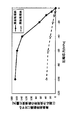
- FIG. 7 shows the iron loss characteristics (magnetic flux density B: 1.0 Tesla, excitation frequency f: 50 Hz) between the steel plate before the siliconization treatment and the magnetic steel plate after the siliconization treatment when the compression stress is applied.
- a steel plate containing about 3% by weight of silicon is used as the steel plate before the siliconization treatment, and a steel plate containing 6.5% by weight of silicon is used as the steel plate after the siliconization treatment.
- the magnetic steel sheet after the siliconization treatment has a smaller iron loss at the time of compressive stress load than the steel plate before the siliconization treatment, and the amount of change is very small even when the stress increases. .
- FIG. 8 is a schematic view showing a motor 700 according to an embodiment of the present invention using the stator core 100 shown in FIG.
- a motor 700 according to an embodiment of the present invention includes a stator core 100, a rotor core 701, and a rotating shaft 705.
- the rotor core 701 may have a configuration in which a large number of annular electromagnetic steel sheet pieces punched out by pressing an electromagnetic steel sheet are stacked in the rotation axis direction.
- a permanent magnet 703 is disposed on the outer diameter side of the rotor core 701.
- the rotor core 701 is attached to the rotating shaft 705 by shrink fitting or spline fitting.
- a coil (not shown) is wound around the teeth portion 103 of the stator core 100.
- Stator core 100 is attached to a motor case (not shown) disposed on the outer diameter side of stator core 100.
- the motor 700 uses the stator 100 in which the silicon concentration in the surface portion of some regions is higher than the silicon concentration in the surface portions of other regions. Therefore, the magnetic flux density of the entire stator core 100 is high and there is no variation. Moreover, the iron loss of the stator core 100 is reduced in the region where the silicon concentration is high. Therefore, high torque and high output can be realized.
- stator core 100 A method for manufacturing the stator core 100 according to an embodiment of the present invention will be described.
- the manufacturing method of the stator core 100 demonstrated below describes the manufacturing method of the stator core 100 comprised by an electromagnetic steel plate piece as an example.
- the manufacturing method of the stator core 100 according to the embodiment of the present invention can be implemented in many different modes, and is not construed as being limited to the description described below.
- a steel plate is prepared as a workpiece.
- a steel plate having components obtained through a known steel making process may be used.
- C is 0.01 wt% or less
- Mn is 0.5 wt% or less
- P is 0.01 wt% or less
- S is 0.01 wt% or less
- the balance is composed of Fe and inevitable impurities.
- Steel plates to be used may be used.
- the steel sheet may contain alloy elements such as Al, Cr, Mo, W, V, Ti, and Sb as long as iron loss characteristics and workability are not impaired.
- the steel plate used as a workpiece is not necessarily limited to the components and numerical ranges described above.
- the Si content in the low silicon steel sheet is preferably less than 3.5% by weight.
- the prepared steel sheet is punched into a predetermined shape by pressing to obtain a steel sheet piece.
- Silica treatment is performed on a partial region of the obtained steel sheet piece.
- silicon powder purity 99.9%
- a carburizing agent are mixed using pure water to produce a paste-like coating agent.
- the silicon powder for example, pure silicon powder (3 Nup, particle size of 75 ⁇ m or less, manufactured by High Purity Chemical Laboratory) can be used.
- the carburizing agent for example, a sun cut charcoal carburizing agent (manufactured by Sankats) containing 80% C charcoal particles and barium carbonate can be used.
- a coating agent is applied to one side or both sides of the steel plate piece in a partial region of the steel plate piece, and then naturally dried.
- blending of the component contained in the coating agent used for the siliconization process of the steel plate piece mentioned above is an example, and is not necessarily limited to the above-mentioned component.
- the coating agent is applied only to the yoke portion constituting portion of the steel sheet piece punched into a desired shape.
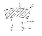
- the coating agent is applied to the yoke portion constituting portion 901 of the steel plate piece 900.
- the yoke portion constituting portion 901 of the steel plate piece 900 to be subjected to the siliconization treatment is indicated by a hatched portion.
- the coating agent may be applied to the other surface side.
- the steel sheet piece 900 coated with the coating agent is heated to about 900 ° C. to 1300 ° C., preferably about 1100 ° C. to 1200 ° C. in an inert atmosphere or a reducing atmosphere, thereby An electrical steel sheet piece having a silicon concentration higher than the silicon concentration in the surface portion of the other region can be obtained.
- An electrical steel sheet piece having a silicon concentration higher than the silicon concentration in the surface portion of the other region can be obtained.
- the silicon steel sheet is selectively subjected to the siliconization treatment so that the yoke portion constituting the electromagnetic steel plate piece has a higher silicon concentration than other regions has been described, but the silicon concentration is relatively high.
- the area to be performed is not limited to the yoke part constituting part.
- the side surface portion of the steel plate piece 1000 may be selectively subjected to the siliconization treatment.
- the region where the siliconization treatment is performed is indicated by hatched portions.
- the steel plate piece 1000 When performing the siliconization treatment on the side surface portion of the steel plate piece 1000, the steel plate piece 1000, which has been pressed and punched into a predetermined shape, is laminated in the axial direction to produce a laminated body of steel plate pieces, and the laminated body is immersed in the laminated body. Silicon treatment may be performed. In this case, it is not necessary to perform the siliconization treatment on each steel plate piece 1000. Therefore, it is possible to reduce the iron loss of the stator core 100 formed of the electromagnetic steel plate pieces while reducing the manufacturing process, and it is possible to realize high torque and high output of the motor using the stator core 100.
- the magnetic flux density in the region excluding the inner peripheral side of the stator core 100 may be increased by relatively increasing the silicon concentration in the surface portion of the region excluding the inner peripheral side of the stator core 100.
- the siliconization treatment may be selectively performed on a part of the portion 1103. In FIG.
- the area where the siliconization process is performed is indicated by the hatched portion.
- the silicon concentration in the surface portion of the region excluding the inner peripheral side of the stator core 100 where the magnetic flux density is relatively high is relatively higher than the silicon concentration in the inner peripheral side surface portion of the stator core 100.
- region except the inner peripheral side of the stator core 100 at the time of a motor drive increases.
- the silicon concentration in the region excluding the inner peripheral side of the stator core 100 is increased, the iron loss of the stator core 100 is reduced. Therefore, it is possible to increase the torque and output of the motor using the stator core 100.
- the iron loss in the region of the stator core where the magnetic flux density is high may be reduced by selectively performing a siliconizing process on the region of the stator core where the magnetic flux density is high and increasing the silicon concentration.
- a siliconizing process on the region of the stator core where the magnetic flux density is high and increasing the silicon concentration.
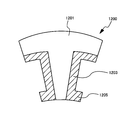
- FIG. 12 in contrast to the region where the siliconization treatment shown in FIG. 11 is performed, a part of the yoke portion constituting portion 1201 of the steel plate piece 1200 corresponding to the inner peripheral side of the stator core 100 and
- the siliconization treatment may be selectively performed on a part of the teeth portion constituting portion 1203.
- the area where the siliconization process is performed is indicated by the hatched portion.
- the saturation magnetic flux density decreases as the silicon concentration increases. For this reason, when the silicon treatment is performed in a region where the magnetic flux density is high when the motor is driven, it is preferable to adjust the silicon concentration so that the saturation magnetic flux density does not fall below the maximum magnetic flux density in the region.
- the siliconizing process is selectively performed on a part of the yoke part constituting part 1201 and a part of the tooth part constituting part 1203 where the magnetic flux density is relatively high.
- the silicon concentration in the surface portion of these regions is made higher than the silicon concentration in the surface portion of the other region of the electromagnetic steel sheet piece.
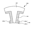
- the magnetic permeability in the vicinity of the flange part forming portion 1205 becomes high, and there is a possibility that leakage magnetic flux is generated. Therefore, for example, as shown in FIG.
- a part of the yoke part constituting part 1301 of the steel plate piece 1300 and a part of the tooth part constituting part 1303 corresponding to the inner peripheral side of the stator core 100 are selected.
- the silicidation process it is not necessary to perform the silicidation process on a part of the heel part constituting part 1305 that is close to the teeth part constituting part 1303, that is, close to the winding (not shown).
- the area where the siliconization process is performed is indicated by the hatched portion.
- the brim part constituting portion 1305 includes a region 1305 a where the siliconizing process is not performed and a region 1305 b where the siliconizing process is performed.
- the steel plate piece is formed so that the flange portion has a tapered wide shape toward the tip of the teeth portion component.
- the shape may be set.
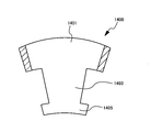
- the both ends of the steel plate piece 1400 in the circumferential direction of the yoke constituting portion 1401 may be selectively subjected to siliconizing treatment.
- the area where the siliconization process is performed is indicated by hatched portions.
- the silicon concentration in the surface portion of both end portions in the circumferential direction of the yoke constituting portion 1401 in the steel plate piece 1400 higher than the silicon concentration in the surface portion in the other region, the magnetic flux density of the yoke constituting portion 1401 is increased. For this reason, even when a gap is generated between the laminates, it is possible to suppress a decrease in magnetic characteristics and to increase the torque and output of the motor using the stator core 100.
- the method of manufacturing the stator core 100 according to the embodiment of the present invention, first, a steel plate as a workpiece is punched into a desired shape by press working to obtain a steel plate piece. Then, the coating agent containing silicon is selectively applied to a partial area in the obtained steel sheet piece and heated to obtain an electromagnetic steel sheet piece having a relatively high silicon concentration in the partial area. Generally, when the silicon content in the steel plate increases, the hardness of the steel plate increases and the workability decreases. However, the method for manufacturing a stator core according to the present invention is excellent in workability because the steel plate is pressed before the siliconization treatment. In addition, by performing a siliconizing treatment on a steel plate piece obtained by pressing using a coating agent, it is possible to selectively perform a siliconizing treatment on a desired region of the steel plate piece.
- the manufacturing method of the stator core which concerns on this invention is not limited to the method described above.
- a cylindrical laminated structure is produced by laminating a plurality of steel plate pieces obtained by press working and welding together, and the outer periphery of the laminated structure
- a stator core having a relatively high silicon concentration in the yoke portion may be manufactured by applying a silicon-containing coating agent to the substrate and heating.
- Table 1 below shows the iron loss characteristics (Wa / b: magnetic loss density of 10 ⁇ a Tesla at excitation frequency b Hz) between the steel plate before the siliconization treatment and the electromagnetic steel plate after the siliconization treatment. .
- a steel plate containing 3.3% by weight of silicon was used as the steel plate before the siliconization treatment.
- the steel plate was subjected to the above-described siliconization treatment to obtain an electromagnetic steel plate containing 6.5% by weight of silicon.
- the iron loss of these steel sheets was measured under the conditions shown in Table 1.
- the manufacturing method of the stator core that performs the siliconization treatment on the steel plate piece obtained by the press working has been described.
- the steel core is punched into a predetermined shape by the press working.
- the obtained steel sheet piece is heated to about 900 ° C. to 1300 ° C., preferably about 1100 ° C. to 1200 ° C. in an inert atmosphere or a reducing atmosphere, so that the silicon concentration in the surface portion of a part of the region is increased.
- region may be obtained.
- the steel sheet piece is selected so that the silicon concentration in a part of the electromagnetic steel sheet pieces constituting the stator core is higher than that in the other areas.
- the silicon concentration in the surface portion of the partial region of the electromagnetic steel sheet piece constituting the stator core is made higher than the silicon concentration in the surface portion of the other region.
- the entire steel plate piece constituting the stator core is subjected to siliconization treatment, and the silicon concentration in the surface portion of some regions is higher than the silicon concentration in the surface portions of other regions.
- the conditions for the siliconizing treatment may be different between some regions and other regions.
- FIG. 15 to FIG. 17 show a siliconized model of an electromagnetic steel plate piece assumed to be used for a stator core of a motor. In addition, it assumed that the siliconization process to a steel plate piece was performed on both surfaces of a steel plate piece.
- An electromagnetic steel plate piece 1500 shown in FIG. 15 is obtained by selectively subjecting a steel plate piece obtained by pressing a commercially available steel plate containing 3% by weight of silicon and having a plate thickness of 0.35 mm to the above-described siliconization treatment. can get.
- the selectively silicified region is indicated by a hatched portion.
- the silicon concentration in the surface portion of the region subjected to the siliconization treatment of the electromagnetic steel plate piece 1500 is relatively higher than the silicon concentration in the region not subjected to the siliconization treatment. That is, in the electromagnetic steel sheet piece 1500 shown in FIG.
- the siliconization treatment is selectively performed on the yoke portion constituting portion 1501 constituting the yoke portion of the stator core, which has a relatively low magnetic flux density when the motor is driven.
- the silicon concentration of the surface portion of the yoke portion constituting portion 1501 is relatively higher than the silicon concentration of the surface portion of the other region of the electromagnetic steel sheet 1500.
- the silicon concentration of the surface portion of the yoke portion constituting portion 1501 is 6.5% by weight, and the surface portion of other regions (tooth portion constituting portion 1503 and flange portion constituting portion 1505) excluding the yoke portion constituting portion 1501.
- the silicon concentration was assumed to be 3% by weight.
- An electromagnetic steel plate piece 1600 shown in FIG. 16 is obtained by subjecting a steel plate piece obtained by pressing a commercially available steel plate having a thickness of 0.35 mm containing 3% by weight of silicon to the entire surface of the steel plate piece. It is obtained by applying.
- the silicon concentration of the entire surface portion of the electromagnetic steel sheet piece 1600 including the yoke portion constituting portion 1601, the teeth portion constituting portion 1603 and the flange portion constituting portion 1605 was assumed to be 6.5% by weight.
- the electromagnetic steel plate piece 1700 shown in FIG. 17 is obtained by pressing a commercially available steel plate containing 3% by weight of silicon and having a plate thickness of 0.35 mm.
- the silicon concentration of the entire surface portion of the electromagnetic steel sheet piece 1700 including the yoke portion constituting portion 1701, the teeth portion constituting portion 1703 and the flange portion constituting portion 1705 is 3% by weight.
- the analysis model structure of the motor used for the calculation was designed as a permanent magnet embedded synchronous motor (IPMSM) using the electromagnetic steel plate pieces 1500, 1600 and 1700 shown in FIGS. 15 to 17 as a stator core.
- IPMSM permanent magnet embedded synchronous motor
- the analysis model structure of the motor was designed so that the thicknesses of the electromagnetic steel plate pieces 1500, 1600, and 1700 constituting the stator core were about 60 mm, respectively.
- a structure using the electromagnetic steel plate piece 1500 as a stator core is referred to as an analysis model A
- a structure using the electromagnetic steel plate piece 1600 as a stator core is referred to as an analysis model B
- a structure using the electromagnetic steel plate piece 1700 as a stator core is referred to as an analysis model C.
- each of the analysis models A to C a commercially available steel plate containing 3% by weight of silicon is used for the rotor core, and N36Z made by Shin-Etsu Chemical Co., Ltd. is used as the permanent magnet for the rotor core, the number of poles is 16, and the number of slots 24, concentrated winding was adopted as the winding method, the winding was wound 50 times, and the resistance value of the winding was assumed to be 0.01 ⁇ .
- the analysis model A using the electromagnetic steel plate piece 1500 for the stator core, in which the silicon concentration in the surface portion of the yoke component 1501 is relatively higher than the silicon concentration in the surface portion in other regions, is the present invention.
- Table 3 below shows the simulation results based on the driving conditions shown in Table 2 for the torque and iron loss of the analysis models A to C.
- the simulation is performed for each of the analysis models A to C at low rotation and high load (rotation speed [rpm]: 1200, current [Arms]: 200), and at high rotation and low load (rotation speed [rpm]: 6000).
- Rotation speed [rpm]: 1200, current [Arms]: 200 the case where the compressive stress generated during the manufacture of the stator core is not considered and the case where the compressive stress is considered are assumed.
- JMAG was used for the design and simulation of the analysis models A to C described above.
- the analysis model A and the analysis model B had a lower iron loss when driven at a lower rotation and a higher load than the analysis model C.
- the efficiency of the analysis model A and the analysis model B at the time of driving at a low rotation and a high load was substantially the same as the efficiency of the analysis model C. This is considered due to the influence of copper loss. Comparing analysis model A and analysis model B, when driving at low rotation and high load, analysis model B has a smaller iron loss than analysis model A, but the magnitude of torque is Is larger than the analysis model B.
- the analysis model A has a larger torque than the analysis model B as described above. This is based on the assumption that the silicon component 15001 of the electromagnetic steel plate piece 1500 constituting the stator core of the motor of the analysis model A is selectively subjected to the siliconization treatment.
- the silicon concentration of the surface portion of the yoke portion of the stator core is relatively higher than the silicon concentration of the surface portion of the other region, and the magnetic flux density of the entire stator core of the analysis model A becomes smaller than that of the stator core of the analysis model B. This is probably because the magnetic flux density was higher.
- the analysis model is larger than the magnitude of the torque of the analysis model C.
- the magnitude of the torque of A is slightly smaller, the magnitude of the torque of the analysis model A is substantially the same as the magnitude of the torque of the analysis model C when considering the compressive stress.
- the analysis model A and the analysis model B have reduced iron loss compared to the analysis model C.
- the efficiency of the analysis model A and the analysis model B is Although substantially the same as the efficiency of the analysis model C, the efficiency of the analysis model A and the analysis model B is slightly higher than the efficiency of the analysis model C when the compressive stress is taken into consideration. Comparing the analysis model A and the analysis model B, the analysis model B has a smaller iron loss than the analysis model A, but the torque of the analysis model A is larger than that of the analysis model B.
- the torque and efficiency of the analysis model A which is a model of the motor according to one embodiment of the present invention, are the torque of the analysis model C, which is the reference model, when driving at low rotation and high load. And substantially the same as efficiency.
- the analysis model A has a lower iron loss and improved efficiency than the analysis model C when driven at a high rotation and a low load. It can also be seen that the torque of the analysis model A is improved over that of the analysis model C during driving at high rotation and low load. Further, in the analysis model A, the magnitude of the torque was large while the efficiency was substantially the same as that of the analysis model B when driving at low rotation and high load and driving at high rotation and low load.
- the steel sheet pieces are selectively subjected to siliconization so that the silicon concentration in a part of the electromagnetic steel sheet pieces constituting the stator core is higher than that in the other areas, and the magnetic steel sheet pieces constituting the stator core.
- SYMBOLS 100 Stator core, 101: Yoke part, 103: Teeth part, 105: collar part, 107, 107a: Electromagnetic steel plate piece, 201, 401: Yoke part structure part, 203,403: Teeth part structure part, 700: Motor
Landscapes
- Engineering & Computer Science (AREA)
- Power Engineering (AREA)
- Chemical & Material Sciences (AREA)
- Dispersion Chemistry (AREA)
- Materials Engineering (AREA)
- Mechanical Engineering (AREA)
- Metallurgy (AREA)
- Organic Chemistry (AREA)
- Manufacturing & Machinery (AREA)
- Iron Core Of Rotating Electric Machines (AREA)
- Manufacture Of Motors, Generators (AREA)
Abstract
【解決手段】本発明のステータコアは、複数の電磁鋼板片を軸方向に積層することにより形成された積層体を周方向に複数接合して環状に配置結合することにより構成されたモータのステータコアであって、各電磁鋼板片は、一体で形成されたヨーク部構成部及びティース部構成部を備え、前記ステータコア分割体の一部の領域の表面部分のケイ素濃度が他の領域の表面部分のケイ素濃度よりも高い。
Description
本発明は、ステータコア、及びそのステータコアを備えたモータに関する。また、本発明は、ステータコアに用いられる電磁鋼板片とその製造方法に関する。
近年、電気機器、電気自動車、ハイブリッド車、ロボットなどの新たな技術の開発に伴い、それらに用いられるモータや発電機に要求される性能が高度化している。例えば、産業用モータ、電気自動車及びハイブリッド車などにおいては、高トルク化、高出力化が求められている。そのため、従来、鉄損が低い電磁鋼板がモータの製造に使用されている。例えば、特許文献1には、表層部と内層部とでケイ素濃度の異なる電磁鋼板がモータコア材料として提案されている。しかしながら、一般的に上述の高濃度のケイ素が添加された電磁鋼板の使用はその飽和磁束密度の低さからトルクの低下を招く可能性があり、モータの高トルク化及び高出力化を実現するにはさらなる検討が必要であった。
本発明は上述の課題を解決するものであって、モータの高トルク化、高出力化が可能なステータコア、及びこれを備えたモータを提供することを目的とする。
また、本発明は、モータの高トルク化、高出力化が可能なステータコアに用いられる電磁鋼板片とその製造方法を提供することを目的とする。
本発明の一実施形態によると、一体で形成されたヨーク部構成部及びティース部構成部を備える、モータのステータコアに用いられる電磁鋼板片であって、一部の領域の表面部分のケイ素濃度が他の領域の表面部分のケイ素濃度よりも高い電磁鋼板片が提供される。
前記電磁鋼板片において、前記一部の領域は、前記ヨーク部構成部であってもよい。
前記電磁鋼板片において、前記一部の領域または前記ヨーク部構成部のケイ素濃度が3.5重量%~6.5重量%であってもよい。
前記電磁鋼板片において、前記他の領域または前記ティース部構成部のケイ素濃度が3.5重量%未満であってもよい。
前記電磁鋼板片において、前記一部の領域又は前記ヨーク部構成部は、プレス加工された鋼板にケイ素を含む塗布剤を塗布し、加熱することによって形成されてもよい。
本発明の一実施形態によると、複数の電磁鋼板片を軸方向に積層することにより形成された積層体を周方向に複数接合して環状に配置結合することにより構成されたモータのステータコアであって、各電磁鋼板片は、一体で形成されたヨーク部構成部及びティース部構成部を備え、前記電磁鋼板片の一部の領域の表面部分のケイ素濃度が他の領域の表面部分のケイ素濃度よりも高い、ステータコアが提供される。
前記ステータコアにおいて、前記一部の領域は、前記ヨーク部構成部であってもよい。
前記ステータコアにおいて、前記一部の領域または前記ヨーク部構成部のケイ素濃度が3.5重量%~6.5重量%であってもよい。
前記ステータコアにおいて、前記他の領域または前記ティース部構成部のケイ素濃度が3.5重量%未満であってもよい。
前記ステータコアにおいて、前記一部の領域又は前記ヨーク部構成部は、プレス加工された鋼板にケイ素を含む塗布剤を塗布し、加熱することによって形成されてもよい。
本発明の一実施形態によると、複数の環状の電磁鋼板片を軸方向に積層して構成されたモータのステータコアであって、前記電磁鋼板片は、ヨーク部構成部及びティース部構成部を備え、前記電磁鋼板片の一部の領域の表面部分のケイ素濃度が他の領域の表面部分のケイ素濃度よりも高い、ステータコアが提供される。
前記ステータコアにおいて、前記一部の領域は、前記ヨーク部構成部であってもよい。
前記ステータコアにおいて、前記一部の領域または前記ヨーク部構成部のケイ素濃度が3.5重量%~6.5重量%であってもよい。
前記ステータコアにおいて、前記他の領域または前記ティース部構成部のケイ素濃度が3.5重量%未満であってもよい。
前記ステータコアにおいて、前記一部の領域又は前記ヨーク部構成部は、プレス加工された鋼板にケイ素を含む塗布剤を塗布し、加熱することによって形成されてもよい。
本発明の一実施形態によると、前記何れかに記載されたステータコアを備えたモータが提供される。
本発明の一実施形態によると、鋼板をプレス加工して、鋼板片を生成し、前記鋼板片の一部の領域にケイ素を含む塗布剤を塗布して加熱する、ことを含む、モータのステータコアに用いられる電磁鋼板片の製造方法が提供される。
前記電磁鋼板片の製造方法において、前記鋼板片は、ヨーク部構成部及びティース部構成部を備え、前記一部の領域は、前記ヨーク部構成部であってもよい。
前記電磁鋼板片の製造方法において、前記塗布剤は、浸炭剤を含んでもよい。
前記電磁鋼板片の製造方法において、前記一部の領域または前記ヨーク部構成部のケイ素濃度が3.5重量%~6.5重量%であってもよい。
前記電磁鋼板片の製造方法において、前記他の領域または前記ティース部構成部のケイ素濃度が3.5重量%未満であってもよい。
本発明によると、モータの高トルク化、高出力化が可能なステータコアに用いられる電磁鋼板片とその製造方法を提供することができる。また、モータの高トルク化、高出力化が可能なステータコア、及びこれを備えたモータを提供することができる。
上述の問題を解決すべく鋭意検討した結果、本発明者らは、モータ駆動時のステータコアにおける磁束密度のばらつき、モータ組み立て時のステータコアの圧入、焼き嵌め、カシメなどによる応力負荷(特に、磁束が流れる方向に平行な圧縮応力)を考慮して、ステータコアを構成する鋼板片の一部領域を選択的に浸珪処理することによって、ステータコア全体の磁束密度を高め、且つ鉄損を低減できることを見出した。
以下、図面を参照して本発明の一実施形態に係るステータコアに用いられる電磁鋼板片とその製造方法、該電磁鋼板片を用いて構成されたステータコア、及び該ステータコアを備えたモータについて説明する。但し、本発明は多くの異なる態様で実施することが可能であり、以下に示す実施形態の記載内容に限定して解釈されるものではない。本発明の実施形態で参照する図面において、同一部分又は同様な機能を有する部分には同一の符号を付し、その繰り返しの説明は省略する。
図1は、本発明の一実施形態に係るモータのステータコア100を示す概略図である。ステータコア100は、環状のヨーク部101、及びヨーク部101の内周に径方向内側に突出するティース部103を備える。ステータコア100は、ティース部103に巻き付けられるコイル(図示せず)に対向し、ティース部103の先端に周方向(ロータの回転方向)に沿って設けられる鍔部105を備えていてもよい。
ステータコア100は、鋼板をプレス加工によって所定の形状に打ち抜くことによって形成した鋼板片に浸珪処理を行って作製した電磁鋼板片107を用いて構成されてもよい。
図2は、ステータコア100を構成する、本発明の一実施形態に係る電磁鋼板片107の一例を示す上面図であり、図3は図2に示した電磁鋼板片107を周方向に対して垂直な回転軸方向(以下、軸方向という)に積層することにより形成された積層体を示す概略図である。電磁鋼板片107は、略T字形状を有し、ヨーク部構成部201、及びティース部構成部203を備える。ヨーク部構成部201及びティース部構成部203は、互いに一体で形成される。また、電磁鋼板片107は、鍔部構成部205を備えてもよい。ステータコア100は、図2に示すような複数の電磁鋼板片107を軸方向に積層して図3に示すような積層体を作製し、該積層体を周方向に複数接合して環状になるように配置することによって構成されてもよい。複数の電磁鋼板片107を回転軸方向に積層して積層体を作製し、該積層体を周方向に環状になるように配置することによって、ヨーク部構成部201は図1に示したステータコア100におけるヨーク部101を構成し、ティース部構成部203はティース部103を構成し、鍔部構成部205は鍔部105を構成する。
尚、電磁鋼板片107の形状は、図2に示したT字形状に限定されない。図4は、図2に示した電磁鋼板片107とは異なる形状を有する電磁鋼板片107aを軸方向に積層した状態を示す概略図である。電磁鋼板片107aは、環形状を有し、環状のヨーク部構成部401、及びヨーク部構成部401の内周に径方向内側に突出するティース部構成部403を備える。電磁鋼板片107aは、ティース部構成部403の先端に周方向(ロータの回転方向)に沿って設けられる鍔部構成部405を備えていてもよい。ステータコア100は、図4に示すような環形状を有する電磁鋼板片107aを軸方向に積層することによって構成されてもよい。
モータ駆動時に、ステータコアでは、ステータコアの部位に応じて磁束密度にばらつきが発生する。例えば、モータ駆動時において、ステータコアのヨーク部では磁束密度が相対的に低くなり、ティース部では相対的に高くなる。そこで、本発明のステータコア100では、ステータコアの一部の領域に選択的に浸珪処理を行うことにより、前記一部の領域のケイ素濃度をステータコアの他の領域のケイ素濃度よりも高くして、ステータコア100全体の磁束密度を高めていることを特徴としている。
本発明の一実施形態に係るステータコア100は、図2及び図4に例示したような電磁鋼板片から構成される。電磁鋼板片は、鋼板片を浸珪処理することにより得られるが、本発明に係る電磁鋼板片においては、鋼板片の一部の領域に選択的に浸珪処理を行うことにより、電磁鋼板片の一部の領域のケイ素濃度を電磁鋼板片の他の領域のケイ素濃度よりも高くする。即ち、少なくとも浸珪処理を施された電磁鋼板片の一部の領域の表面部分のケイ素濃度は、浸珪処理を施されていない他の領域の表面部分のケイ素濃度よりも高くなる。
尚、電磁鋼板片の板厚方向への浸珪処理は、電磁鋼板片の板厚方向の全域に及んでいてもよく、電磁鋼板片の板厚方向の一部の領域のみであってよい。例えば、鋼板片の両面から浸珪処理を施して、鋼板片の板厚方向全域が浸珪処理されてもよく、或いは、鋼板片の板厚方向の中間部分を除いた、鋼板片の両面側のみが所定の深さまで浸珪処理されてもよい。また、鋼板片の片面から浸珪処理を施して、他方の面を浸珪処理されない部分としてもよい。
例えば、モータ駆動の際に、磁束密度が相対的に低くなるヨーク部101のケイ素濃度を、ティース部103のケイ素濃度よりも高くしてもよい。ヨーク部101のケイ素濃度を相対的に高くすることによって、モータ駆動時のヨーク部101の磁束密度が高くなる。また、ヨーク部101のケイ素濃度が高くなるため、ステータコア100の鉄損が低減される。そのため、本発明の一実施形態に係るステータコア100を使用するモータの高トルク化及び高出力化が可能になる。
ヨーク部101におけるケイ素濃度は、3.5重量%以上6.5重量%以下であることが好ましい。また、ティース部103におけるケイ素濃度は、ヨーク部101のケイ素濃度よりも低ければよい。ティース部103は、モータ駆動時の磁束密度が相対的に高いため、ティース部103においてケイ素が多く含有されていると、ティース部103の飽和磁束密度が低下する。そのため、浸珪処理工程におけるケイ素の拡散を考慮して、ティース部103のケイ素濃度は0重量%以上3.5重量%未満であることが好ましい。
ヨーク部101のケイ素濃度を選択的に高くする場合、ステータ100のヨーク部101を構成する、電磁鋼板片107、107aにおけるヨーク部構成部201、401のケイ素濃度がティース部構成部203、403のケイ素濃度よりも高くなるよう、鋼板片を選択的に浸珪処理する。したがって、電磁鋼板片107、107aにおいて、浸珪処理を施されたヨーク部構成部201、401の表面部分のケイ素濃度は、浸珪処理を施されていないティース部構成部203、403の表面部分のケイ素濃度よりも高くなる。ヨーク部構成部201、401のケイ素濃度を相対的に高くすることによって、モータ駆動時のヨーク部101の磁束密度が高くなり、且つステータコア100の鉄損が低減される。
図5は、図2に示した本発明の一実施形態に係る電磁鋼板片107の上面図である。図6の(a)は図5に示した電磁鋼板片107の斜視図であり、図6の(b)は図5に示した電磁鋼板片107のA-A´線に沿った断面図である。図5及び図6において、斜線で示す領域は、他の領域よりも相対的にケイ素濃度が高い領域である。
本発明の一実施形態に係る電磁鋼板片が電磁鋼板片107である場合、図5及び図6に示すように、ヨーク部構成部201のケイ素濃度を他の領域(ティース部構成部203及び鍔部構成部205)のケイ素濃度よりも高くするように、鋼板片を選択的に浸珪処理する。浸珪処理を施されたヨーク部構成部201の表面部分のケイ素濃度は、浸珪処理を施されていないティース部構成部203及び鍔部構成部205の表面部分のケイ素濃度よりも高くなる。
ヨーク部構成部201、401におけるケイ素濃度は、3.5重量%以上6.5重量%以下であることが好ましい。また、ティース部構成部203、403におけるケイ素濃度は、ヨーク部構成部201、401におけるケイ素濃度よりも低ければよく、ヨーク部構成部201、401の浸珪処理工程におけるケイ素の拡散を考慮して、0重量%以上3.5重量%未満であることが好ましい。
本発明の一実施形態に係るステータコア100では、ステータコア100を構成する電磁鋼板片107、107aの一部の領域のケイ素濃度を電磁鋼板片107、107aの他の領域のケイ素濃度よりも高くするように、鋼板片の一部に選択的に浸珪処理する。結果として、ステータコア100の一部の領域の表面部分のケイ素濃度が、ステータコア100の他の領域の表面部分のケイ素濃度よりも高くなる。一例として、上述したようにモータ駆動時の磁束密度が相対的に低いヨーク部101を構成するヨーク部構成部201、401のケイ素濃度が他の領域のケイ素濃度よりも高くなるように浸珪処理を行ってもよい。これにより、モータ駆動時のヨーク部101の磁束密度が高くなる。よって、ステータコア100全体の磁束密度が高くなり、且つばらつきがなくなる。また、ヨーク部101においてステータコア100の鉄損を低減することができる。そのため、ステータコア100を使用するモータの高トルク化及び高出力化を実現することができる。
以上では、浸珪処理を行ってケイ素濃度を相対的に高くする領域として、ステータコア100を構成する電磁鋼板片107、107aのヨーク部構成部201、401を具体的な例として挙げたが、本発明の一実施形態に係るステータコア100を構成する電磁鋼板片107aにおいて、浸珪処理を行ってケイ素濃度を高くする領域は、ヨーク部構成部201、401に限定されるわけではない。
例えば、モータ組み立て時において、ステータコアの圧入、焼き嵌め、カシメなどによる応力負荷により、ステータコアの一部の領域で磁気劣化が大きくなる虞がある。そのため、モータ組み立て時において、大きな応力、特に、磁束が流れる方向に平行な圧縮応力がかかるステータコアの領域に選択的に浸珪処理を行ってもよい。大きな応力がかかる領域のケイ素濃度を相対的に高くすることにより、応力負荷による該領域の磁気劣化を抑制し、モータの高トルク化及び高出力化を実現することができる。
図7は、浸珪処理をする前の鋼板と浸珪処理した後の電磁鋼板との圧縮応力負荷時の鉄損特性(磁束密度B:1.0Tesla、励磁周波数f:50Hz)を示している。浸珪処理前の鋼板としては、ケイ素を約3重量%含む鋼板を用い、浸珪処理後の鋼板としては、ケイ素を6.5重量%含む鋼板を用いている。図7を参照すると、浸珪処理後の電磁鋼板では、浸珪処理前の鋼板に比べて、圧縮応力負荷時の鉄損が小さく、応力が増してもその変化量が非常に小さいことが分かる。
図8は、図1に示したステータコア100を用いた、本発明の一実施形態に係るモータ700を示す概略図である。本発明の一実施形態に係るモータ700は、ステータコア100、ロータコア701及び回転軸705を備える。ロータコア701は、電磁鋼板をプレス加工することによって打ち抜いた環状の電磁鋼板片を回転軸方向に多数積層した構成を有してもよい。ロータコア701の外径側には永久磁石703が配置される。ロータコア701は、焼き嵌め又はスプライン嵌合などによって回転軸705に取り付けられる。
ステータコア100のティース部103には、コイル(図示せず)が巻き付けられている。ステータコア100は、ステータコア100の外径側に配置されたモータケース(図示せず)に取り付けられる。
本発明の一実施形態に係るモータ700は、一部の領域の表面部分のケイ素濃度を他の領域の表面部分のケイ素濃度よりも高くしたステータ100を使用している。そのため、ステータコア100全体の磁束密度が高く、且つばらつきがない。また、ケイ素濃度が高い領域においてステータコア100の鉄損が低減されている。そのため、高トルク化及び高出力化を実現することができる。
(ステータコアの製造方法)
本発明の一実施形態に係るステータコア100の製造方法について説明する。尚、以下に説明するステータコア100の製造方法は、一例として、電磁鋼板片により構成されるステータコア100の製造方法を述べる。本発明の一実施形態に係るステータコア100の製造方法は多くの異なる態様で実施することが可能であり、以下に示す記載内容に限定して解釈されるものではない。
本発明の一実施形態に係るステータコア100の製造方法について説明する。尚、以下に説明するステータコア100の製造方法は、一例として、電磁鋼板片により構成されるステータコア100の製造方法を述べる。本発明の一実施形態に係るステータコア100の製造方法は多くの異なる態様で実施することが可能であり、以下に示す記載内容に限定して解釈されるものではない。
まず、被加工材として鋼板を準備する。鋼板としては、公知の製鋼プロセスを経て得られる成分を有する鋼板を使用してもよい。例えば、Cを0.01重量%以下、Mnを0.5重量%以下、Pを0.01重量%以下、Sを0.01重量%以下を含有し、残部がFe及び不可避的不純物から構成される鋼板を使用してもよい。この他に、鉄損特性、加工性を阻害しない範囲で、鋼板は、Al、Cr、Mo、W、V、Ti、Sb等の合金元素を含有してもよい。尚、被加工材として使用される鋼板は、以上に述べた成分、数値範囲に限定されるわけではない。また、被加工材として使用される鋼板として、Siを含有する低ケイ素鋼板を用いてもよい。低ケイ素鋼板におけるSiの含有量は、3.5重量%未満であることが好ましい。
次に、準備した鋼板をプレス加工により、所定の形状に打ち抜いて、鋼板片を得る。得られた鋼板片の一部の領域に浸珪処理を行う。まず、ケイ素粉末(純度99.9%)及び浸炭剤を純水を用いて混合し、ペースト状の塗布剤を作製する。ケイ素粉末としては、例えば、純珪素粉末(3Nup、粒径75μm以下、高純度化学研究所製)を用いることができる。また、浸炭剤としては、例えば、木炭粉粒80%Cと炭酸バリウムとを含むサンカツチャコール浸炭剤(サンカツ社製)を用いることができる。鋼板片の一部の領域において鋼板片の片面もしくは両面に塗布剤を塗布し、自然乾燥させる。尚、上述した鋼板片の浸珪処理に用いる塗布剤に含まれる成分の配合は一例であり、上述の成分に限定されるわけではない。
ステータコア100のヨーク部101のケイ素濃度を高くする場合、所望の形状に打ち抜いた鋼板片のヨーク部構成部にのみ塗布剤を塗布する。例えば、図9に示すとおり、鋼板片900が、図2に示した電磁鋼板片107と同じ形状である場合、鋼板片900のヨーク部構成部901に塗布剤を塗布する。尚、図9において、浸珪処理を行う鋼板片900のヨーク部構成部901を斜線部で示した。図9では、鋼板片901の一面側のみを示しているが、他面側にも塗布剤を塗布してもよい。
その後、塗布剤を塗布した鋼板片900を非活性雰囲気下又は還元雰囲気下において900℃~1300℃程度、好ましくは、1100℃~1200℃程度に加熱することにより、一部の領域の表面部分のケイ素濃度が他の領域の表面部分のケイ素濃度よりも高い電磁鋼板片を得ることができる。得られた電磁鋼板片を軸方向に積層して図3に示したような電磁鋼板片の積層体を作製し、該積層体を周方向に複数接合して環状になるように配置することによって、本発明の一実施形態に係るステータコア100が得られる。電磁鋼板片は、互いに溶接されてもよい。また、電磁鋼板片は、締め代をもって焼き嵌めなどにより、モータケースに取り付けられてもよい。
以上では、電磁鋼板片のヨーク部構成部が他の領域に比してケイ素濃度が高くなるよう、鋼板片に選択的に浸珪処理を行う例を説明したが、ケイ素濃度を相対的に高くする領域はヨーク部構成部のみに限定されるわけではない。例えば、図10に示すように、鋼板片1000の側面部に選択的に浸珪処理を施してもよい、図10において、浸珪処理を行う領域を斜線部で示した。鋼板片1000の側面部に浸珪処理を行う場合、プレス加工して所定の形状に打ち抜いた鋼板片1000を軸方向に積層して鋼板片の積層体を作製し、該積層体にまとめて浸珪処理を行ってもよい。この場合、一つ一つの鋼板片1000に浸珪処理を行う必要がない。そのため、製造工程を低減しながら、電磁鋼板片により形成されたステータコア100の鉄損を低減することができ、ステータコア100を使用するモータの高トルク化及び高出力化を実現することができる。
また、モータ駆動時において、ステータコアの内周側は磁束密度が相対的に高くなり、ステータコアの内周側を除いた領域の磁束密度が相対的に低くなる傾向がみられる。そのため、ステータコア100の内周側を除く領域の表面部分のケイ素濃度を相対的に高くすることにより、ステータコア100の内周側を除く領域の磁束密度を上げてもよい。例えば、図11に示すように、ステータコア100の外周側に対応する、鋼板片1100のヨーク部構成部1101の一部の領域と、ステータコア100の内周側に対応する領域を除く、ティース部構成部1103の一部の領域とに選択的に浸珪処理を行ってもよい。図11において、浸珪処理を行う領域を斜線部で示した。モータ駆動の際に、磁束密度が相対的に高くなるステータコア100の内周側を除いた領域の表面部分のケイ素濃度を、ステータコア100の内周側の表面部分のケイ素濃度よりも相対的に高くすることによって、モータ駆動時の、ステータコア100の内周側を除いた領域の磁束密度が上がる。また、ステータコア100の内周側を除いた領域のケイ素濃度が高くなるため、ステータコア100の鉄損が低減される。そのため、ステータコア100を使用するモータの高トルク化及び高出力化が可能になる。
また、モータ駆動時において、高磁束密度となる部分は、鉄損が増加する。そのため、モータ駆動時における、ステータコアの高磁束密度となる領域に選択的に浸珪処理を行い、ケイ素濃度を高くすることにより、ステータコアの高磁束密度となる領域の鉄損を低減させてもよい。例えば、図12に示すように、図11に示した浸珪処理を行う領域とは逆に、ステータコア100の内周側に対応する、鋼板片1200のヨーク部構成部1201の一部の領域と、ティース部構成部1203の一部の領域とに選択的に浸珪処理を行ってもよい。図12において、浸珪処理を行う領域を斜線部で示した。一方、上述したようにケイ素濃度が高いほど飽和磁束密度が低下する。そのため、モータ駆動時に高磁束密度となる領域に浸珪処理する場合は、その領域の最大磁束密度を下回らない飽和磁束密度となるようにケイ素濃度を調節することが好ましい。
また、モータ駆動時において、ステータの鍔部(図1及び図8における鍔部105)付近では、ステータの内部を通らずにステータの外側を通る漏れ磁束が発生し、この漏れ磁束がステータの巻き線を通ることで銅損が生じる。したがって、ステータの鍔部付近で発生する漏れ磁束を低減できれば、モータの高トルク化及び高出力化が可能になる。
上述した図12では、モータ駆動時において、磁束密度が比較的高くなるヨーク部構成部1201の一部の領域と、ティース部構成部1203の一部の領域とに選択的に浸珪処理を行って、これらの領域の表面部分のケイ素濃度を電磁鋼板片の他の領域の表面部分のケイ素濃度に比べて高くする例を示した。しかし、この場合、鍔部構成部1205付近の透磁率が高くなり、漏れ磁束が発生する虞がある。そのため、例えば、図13に示すように、ステータコア100の内周側に対応する、鋼板片1300のヨーク部構成部1301の一部の領域と、ティース部構成部1303の一部の領域とに選択的に浸珪処理を行う場合、ティース部構成部1303に近い、即ち、巻き線(図示せず)に近接する鍔部構成部1305の一部に対して浸珪処理を行わなくてもよい。図13において、浸珪処理を行う領域を斜線部で示した。図13に示す、鋼板片1300において、鍔部構成部1305は、浸珪処理を行わない領域1305aと浸珪処理を行う領域1305bとを含む。鍔部構成部1305のティース部構成部1303に近い領域1305bに浸珪処理を行わないことにより、モータ駆動時に、巻き線に近接する鍔部が高透磁率になることを防止することができる。したがって、巻き線に近接する鍔部付近での漏れ磁束の発生を抑制し、銅損を低減することができる。
尚、巻き線に近接する鍔部が高透磁率になることを防止するために、鍔部構成部が、ティース部構成部の先端に向かってテーパー状に幅広の形状を有するように、鋼板片の形状を設定してもよい。
また、複数の電磁鋼板片を軸方向に積層して積層体を形成し、該積層体を周方向に複数接合してステータコア100を構成する場合、積層体と積層体との間に空隙が発生し、磁気特性が低下してしまう虞がある。この磁気特性の低下を補うために、例えば、図14に示すように、鋼板片1400におけるヨーク構成部1401の周方向の両端部に選択的に浸珪処理を行ってもよい。図14において、浸珪処理を行う領域を斜線部で示した。鋼板片1400におけるヨーク構成部1401の周方向の両端部の表面部分のケイ素濃度を他の領域の表面部分のケイ素濃度よりも高くすることにより、ヨーク構成部1401の磁束密度が高くなる。そのため、積層体と積層体との間に空隙が発生した場合でも、磁気特性の低下を抑制し、ステータコア100を使用するモータの高トルク化及び高出力化が可能になる。
上述したように、本発明の一実施形態に係るステータコア100の製造方法では、まず、被加工材である鋼板をプレス加工によって所望の形状に打ち抜いて、鋼板片を得る。その後、ケイ素を含む塗布剤を、得られた鋼板片における一部の領域に選択的に塗布して、加熱することにより、一部の領域においてケイ素濃度が相対的に高い電磁鋼板片を得る。一般的に、鋼板におけるケイ素の含有量が増大すると、鋼板の硬度が増大し、加工性が低下する。しかしながら、本発明に係るステータコアの製造方法では、浸珪処理の前に鋼板をプレス加工するため、加工性に優れる。また、プレス加工により得られた鋼板片を塗布剤を用いて浸珪処理を行うことにより、鋼板片の所望の領域に選択的に浸珪処理することができる。
尚、本発明に係るステータコアの製造方法は以上に述べた方法に限定されない。例えば、ステータコアのヨーク部のケイ素濃度を相対的に高くする場合、プレス加工によって得られた鋼板片を複数積層して互いに溶接することによって円筒状の積層構造体を作製し、積層構造体の外周にケイ素を含有する塗布剤を塗布し、加熱することによって、ヨーク部のケイ素濃度が相対的に高いステータコアを製造してもよい。
以下の表1は、浸珪処理をする前の鋼板と浸珪処理した後の電磁鋼板との鉄損特性(Wa/b:励磁周波数bHzで磁束密度10×aTeslaの鉄損)を示している。浸珪処理前の鋼板としては、ケイ素を3.3重量%含む鋼板を用いた。この鋼板に、上述したような浸珪処理を施し、ケイ素を6.5重量%含む電磁鋼板を得た。表1で示す条件でこれらの鋼板の鉄損を測定した。

表1を参照すると、ケイ素を6.5重量%含む浸珪処理後の電磁鋼板では、浸珪処理前の鋼板に比べて、鉄損が減少していることが分かる。したがって、モータ駆動時の磁束密度にばらつきのあるステータコアを構成する鋼板片一部の領域に選択的に浸珪処理を行うことにより、モータ駆動時のステータコア全体の磁束密度を高め、且つステータコアの鉄損を低減することができ、ステータコアを使用するモータの高トルク化及び高出力化を実現することができる。
以上では、プレス加工によって得られた鋼板片に浸珪処理を行うステータコアの製造方法を説明したが、被加工材の鋼板にケイ素を含む塗布剤を塗布した後に、プレス加工により所定の形状に打ち抜き、その後、得られた鋼板片を非活性雰囲気下又は還元雰囲気下において900℃~1300℃程度、好ましくは、1100℃~1200℃程度に加熱することにより、一部の領域の表面部分のケイ素濃度が他の領域の表面部分のケイ素濃度よりも高い電磁鋼板片を得てもよい。
以上に述べたように、本発明の一実施形態に係るステータコアでは、ステータコアを構成する電磁鋼板片の一部の領域のケイ素濃度が他の領域に比して高くなるように、鋼板片に選択的に浸珪処理を行うことにより、ステータコアを構成する電磁鋼板片の前記一部の領域の表面部分のケイ素濃度を他の領域の表面部分のケイ素濃度よりも高くしている。これにより、モータ駆動時のステータコア全体の磁束密度を高め、且つステータコアの鉄損を低減することができ、ステータコアを使用するモータの高トルク化及び高出力化を実現することができる。
尚、本発明の一実施形態に係るステータコアでは、ステータコアを構成する鋼板片全体に浸珪処理を行い、且つ、一部の領域の表面部分のケイ素濃度が他の領域の表面部分のケイ素濃度よりも高くなるように、一部の領域と他の領域とで、浸珪処理の際の条件などを異なるようにしてもよい。
以下、本発明の一実施形態に係るモータのトルク及び鉄損について計算によって得られたシミュレーション結果を説明する。但し、本発明は、以下に述べる構成に限定されるわけではない。計算に用いられたモータの解析モデルについて、以下に説明する。
計算に用いたモータの解析モデル構造は、図15~図17に示す電磁鋼板片をステータコアに使用した構造を想定して設計された。図15~図17は、モータのステータコアに使用するものとして想定された電磁鋼板片の浸珪モデルを示している。尚、鋼板片への浸珪処理は、鋼板片の両面に行うことを想定した。
図15に示す電磁鋼板片1500は、ケイ素を3重量%含む、板厚0.35mmの市販の鋼板をプレス加工して得た鋼板片に、上述したような浸珪処理を選択的に施して得られる。図15において、選択的に浸珪処理された領域は斜線部で示されている。電磁鋼板片1500の浸珪処理された領域の表面部分のケイ素濃度は、浸珪処理されていない領域のケイ素濃度よりも相対的に高い。即ち、図15に示す電磁鋼板片1500では、モータ駆動時の磁束密度が相対的に低い、ステータコアのヨーク部を構成するヨーク部構成部1501に選択的に浸珪処理を行ったことを想定しており、ヨーク部構成部1501の表面部分のケイ素濃度が、電磁鋼板片1500のその他の領域の表面部分のケイ素濃度よりも相対的に高い。電磁鋼板片1500では、ヨーク部構成部1501の表面部分のケイ素濃度を6.5重量%、ヨーク部構成部1501を除く他の領域(ティース部構成部1503及び鍔部構成部1505)の表面部分のケイ素濃度を3重量%と想定した。
図16に示す電磁鋼板片1600は、ケイ素を3重量%含む、板厚0.35mmの市販の鋼板をプレス加工して得た鋼板片に、上述したような浸珪処理を鋼板片の全面に施して得られる。ヨーク部構成部1601、ティース部構成部1603及び鍔部構成部1605を含む電磁鋼板片1600の全体の表面部分のケイ素濃度は、6.5重量%と想定した。図17に示す電磁鋼板片1700は、ケイ素を3重量%含む、板厚0.35mmの市販の鋼板をプレス加工して得られる。ヨーク部構成部1701、ティース部構成部1703及び鍔部構成部1705を含む電磁鋼板片1700の全体の表面部分のケイ素濃度は、3重量%である。
計算に用いたモータの解析モデル構造は、図15~図17に示した電磁鋼板片1500、1600、1700をステータコアに使用した永久磁石埋込型同期モータ(IPMSM)として設計された。ここで、モータの解析モデル構造は、ステータコアを構成する電磁鋼板片1500、1600、1700の積厚がそれぞれ約60mmとなるように設計された。以下、電磁鋼板片1500をステータコアに使用した構造を解析モデルA、電磁鋼板片1600をステータコアに使用した構造を解析モデルB、及び電磁鋼板片1700をステータコアに使用した構造を解析モデルCとする。解析モデルA~Cは、それぞれ、ケイ素を3重量%含む市販の鋼板をロータコアに用い、ロータコアに用いられる永久磁石としては、信越化学工業株式会社製のN36Zを用い、極数は16、スロット数は24、巻線方式は集中巻を採用し、巻線は50回巻、巻線の抵抗値は0.01Ωを想定した。解析モデルA~Cのうち、ヨーク構成部1501の表面部分のケイ素濃度がその他の領域の表面部分のケイ素濃度よりも相対的に高い電磁鋼板片1500をステータコアに用いた解析モデルAが、本発明の一実施形態に係るモータのモデルである。また、鋼板片への全面浸珪処理を想定した解析モデルBを比較モデルとし、鋼板片の浸珪処理を想定していない解析モデルCをリファレンスモデルとした。解析モデルA~Cの駆動条件は、以下の表2に示す。

解析モデルA~Cのトルク及び鉄損について、表2に示した駆動条件に基づいたシミュレーション結果を以下の表3に示す。シミュレーションは、解析モデルA~Cそれぞれについて、低回転且つ高負荷(回転数[rpm]:1200、電流[Arms]:200)時における駆動、及び高回転且つ低負荷(回転数[rpm]:6000、電流[Arms]:40)時における駆動に対して、ステータコア製造時に生じる圧縮応力を考慮しない場合と、圧縮応力を考慮した場合と、を想定した。尚、以上に説明した解析モデルA~Cの設計及びシミュレーションには、JMAGを用いた。

表3を参照すると、解析モデルA及び解析モデルBは、解析モデルCに比べて低回転且つ高負荷での駆動時に鉄損が減少した。しかしながら、低回転且つ高負荷での駆動時における解析モデルA及び解析モデルBの効率は、解析モデルCの効率と略同じであった。これは、銅損の影響のためと考えられる。解析モデルAと解析モデルBとを比較すると、低回転且つ高負荷での駆動時では、解析モデルBのほうが解析モデルAに比べて、鉄損が小さいものの、トルクの大きさは、解析モデルAの方が解析モデルBよりも大きい。これは、解析モデルBのモータのステータコアを構成する電磁鋼板片1600の全面に浸珪処理を行うことを想定したため、解析モデルBのステータコアで磁束密度が低下した領域が発生し、解析モデルBのモータのトルクが低下したと考えられる。一方、解析モデルAは、上述したように解析モデルBに比べてトルクが大きい。これは、解析モデルAのモータのステータコアを構成する電磁鋼板片1500のヨーク構成部1501に選択的に浸珪処理を行ったことを想定したため、解析モデルAにおいて、モータ駆動時の磁束密度が相対的に低い、ステータコアのヨーク部の表面部分のケイ素濃度が、その他の領域の表面部分のケイ素濃度よりも相対的に高くなり、解析モデルAのステータコア全体の磁束密度が、解析モデルBのステータコアの磁束密度よりも高くなったためだと考えられる。また、低回転且つ高負荷での駆動時での解析モデルAと解析モデルCのトルクの大きさを比べると、圧縮応力を考慮しなかった場合は、解析モデルCのトルクの大きさよりも解析モデルAのトルクの大きさが若干小さいが、圧縮応力を考慮した場合は、解析モデルAのトルクの大きさは解析モデルCのトルクの大きさと略同じであった。
高回転且つ低負荷では、解析モデルA及び解析モデルBは、解析モデルCに比べて鉄損が減少しており、圧縮応力を考慮しなかった場合は、解析モデルA及び解析モデルBの効率は解析モデルCの効率と略同じだが、圧縮応力を考慮した場合、解析モデルA及び解析モデルBの効率は解析モデルCの効率よりも若干向上した。解析モデルAと解析モデルBとを比較すると、解析モデルBのほうが解析モデルAに比べて、鉄損が小さいものの、トルクの大きさは、解析モデルAの方が解析モデルBよりも大きい。これは、解析モデルAのモータにおいて、モータ駆動時の磁束密度が相対的に低い、ステータコアのヨーク部の表面部分のケイ素濃度が、その他の領域の表面部分のケイ素濃度よりも相対的に高いため、解析モデルAのステータコア全体の磁束密度が、解析モデルBのステータコアの磁束密度よりも高くなったためだと考えられる。また、解析モデルAと解析モデルCのトルクの大きさを比べると、圧縮応力を考慮しなかった場合は解析モデルAと解析モデルCのトルクの大きさは同一であり、圧縮応力を考慮した場合は、解析モデルAのトルクの大きさが解析モデルCのトルクよりも大きくなった。
以上に述べたシミュレーション結果より、本発明の一実施形態に係るモータのモデルである解析モデルAのトルク及び効率は、低回転且つ高負荷での駆動時において、リファレンスモデルである解析モデルCのトルク及び効率と略同じである。また、解析モデルAは、高回転且つ低負荷での駆動時において、解析モデルCよりも鉄損が減少し、効率が向上した。また、高回転且つ低負荷での駆動時において、解析モデルAは、解析モデルCよりもトルクの大きさが向上したことが分かる。さらに、解析モデルAは、低回転且つ高負荷での駆動時及び高回転且つ低負荷での駆動時において、解析モデルBに比べて、効率は略同じながらトルクの大きさが大きくなった。これにより、ステータコアを構成する電磁鋼板片の一部の領域のケイ素濃度が他の領域に比して高くなるように、鋼板片に選択的に浸珪処理を行い、ステータコアを構成する電磁鋼板片の前記一部の領域の表面部分のケイ素濃度を他の領域の表面部分のケイ素濃度よりも高くすることにより、モータ駆動時のステータコア全体の磁束密度を高め、且つステータコアの鉄損を低減することができ、ステータコアを使用するモータの高トルク化及び高出力化を実現することができることがわかる。
100:ステータコア、101:ヨーク部、103:ティース部、105:鍔部、107,107a:電磁鋼板片、201,401:ヨーク部構成部、203,403:ティース部構成部、700:モータ
Claims (16)
- 一体で形成されたヨーク部構成部及びティース部構成部を備える、モータの電磁鋼板片であって、
一部の領域の表面部分のケイ素濃度が他の領域の表面部分のケイ素濃度よりも高い、モータの電磁鋼板片。 - 前記一部の領域は、前記ヨーク部構成部である、請求項1に記載のモータの電磁鋼板片。
- 前記一部の領域または前記ヨーク部構成部のケイ素濃度が3.5重量%~6.5重量%である、請求項1または2に記載のモータの電磁鋼板片。
- 前記他の領域のケイ素濃度が3.5重量%未満である、請求項1に記載のモータの電磁鋼板片。
- 複数の電磁鋼板片を軸方向に積層することにより形成された積層体を周方向に複数接合して環状に配置結合することにより構成されたモータのステータコアであって、
各電磁鋼板片は、一体で形成されたヨーク部構成部及びティース部構成部を備え、
前記電磁鋼板片の一部の表面部分の領域のケイ素濃度が他の領域の表面部分のケイ素濃度よりも高い、ステータコア。 - 複数の環状の電磁鋼板片を軸方向に積層して構成されたモータのステータコアであって、
前記電磁鋼板片は、一体で形成されたヨーク部構成部及びティース部構成部を備え、
前記電磁鋼板片の一部の領域の表面部分のケイ素濃度が他の領域の表面部分のケイ素濃度よりも高い、ステータコア。 - 前記一部の領域は、前記ヨーク部構成部である、請求項5または6に記載のステータコア。
- 前記一部の領域のケイ素濃度が3.5重量%~6.5重量%である、請求項5または6に記載のステータコア。
- 前記ヨーク部構成部のケイ素濃度が3.5重量%~6.5重量%である、請求項7に記載のステータコア。
- 前記他の領域のケイ素濃度が3.5重量%未満である、請求項5または6に記載のステータコア。
- 請求項5乃至10の何れか一項に記載されたステータコアを備えたモータ。
- 鋼板をプレス加工して、鋼板片を生成し、
前記鋼板片の一部の領域にケイ素を含む塗布剤を塗布して加熱する、
ことを含む、電磁鋼板片の製造方法。 - 前記鋼板片は、ヨーク部構成部及びティース部構成部を備え、
前記一部の領域は、前記ヨーク部構成部である、請求項12に記載の電磁鋼板片の製造方法。 - 前記塗布剤は、浸炭剤を含む、請求項12または13に記載の電磁鋼板片の製造方法。
- 前記一部の領域または前記ヨーク部構成部のケイ素濃度を3.5重量%~6.5重量%とする、請求項12または13に記載の電磁鋼板片の製造方法。
- 前記一部の領域を除く他の領域のケイ素濃度を3.5重量%未満とする、請求項12に記載の電磁鋼板片の製造方法。
Applications Claiming Priority (2)
| Application Number | Priority Date | Filing Date | Title |
|---|---|---|---|
| JP2015176360 | 2015-09-08 | ||
| JP2015-176360 | 2015-09-08 |
Publications (1)
| Publication Number | Publication Date |
|---|---|
| WO2017043601A1 true WO2017043601A1 (ja) | 2017-03-16 |
Family
ID=58240872
Family Applications (1)
| Application Number | Title | Priority Date | Filing Date |
|---|---|---|---|
| PCT/JP2016/076512 Ceased WO2017043601A1 (ja) | 2015-09-08 | 2016-09-08 | ステータコア、ステータコアを備えたモータ、これに用いられる電磁鋼板片及びその製造方法 |
Country Status (1)
| Country | Link |
|---|---|
| WO (1) | WO2017043601A1 (ja) |
Cited By (5)
| Publication number | Priority date | Publication date | Assignee | Title |
|---|---|---|---|---|
| JP2020115721A (ja) * | 2019-01-17 | 2020-07-30 | 日本製鉄株式会社 | 分割型固定子および回転電機 |
| WO2021116649A1 (en) * | 2019-12-13 | 2021-06-17 | Dyson Technology Limited | An electric motor |
| CN113056859A (zh) * | 2018-12-17 | 2021-06-29 | 日本制铁株式会社 | 粘接层叠铁芯、其制造方法以及旋转电机 |
| NL2025517B1 (en) * | 2020-05-06 | 2021-11-23 | Tecnotion Assets B V | Electric motor and primary part |
| JP2022507823A (ja) * | 2018-11-20 | 2022-01-18 | シーアールエス・ホールディングス・リミテッド・ライアビリティ・カンパニー | マルチマテリアルのセグメント化された回転電機用固定子の製造方法とその方法で製造された固定子 |
Citations (6)
| Publication number | Priority date | Publication date | Assignee | Title |
|---|---|---|---|---|
| JPS5532440A (en) * | 1978-08-28 | 1980-03-07 | Toshiba Corp | Yoke of high magnetic permeability and flux density |
| JPS55166135U (ja) * | 1979-05-16 | 1980-11-29 | ||
| JPS60134738A (ja) * | 1983-12-21 | 1985-07-18 | Touriyou Kogyo Kk | 小型電動機 |
| JPH03235629A (ja) * | 1990-02-08 | 1991-10-21 | Mitsubishi Electric Corp | 回転電機 |
| JP2005281843A (ja) * | 2004-03-31 | 2005-10-13 | Jfe Steel Kk | 連続ラインによる高珪素鋼板の製造方法 |
| JP2009263782A (ja) * | 2008-03-31 | 2009-11-12 | Jfe Steel Corp | 方向性電磁鋼板およびその製造方法 |
-
2016
- 2016-09-08 WO PCT/JP2016/076512 patent/WO2017043601A1/ja not_active Ceased
Patent Citations (6)
| Publication number | Priority date | Publication date | Assignee | Title |
|---|---|---|---|---|
| JPS5532440A (en) * | 1978-08-28 | 1980-03-07 | Toshiba Corp | Yoke of high magnetic permeability and flux density |
| JPS55166135U (ja) * | 1979-05-16 | 1980-11-29 | ||
| JPS60134738A (ja) * | 1983-12-21 | 1985-07-18 | Touriyou Kogyo Kk | 小型電動機 |
| JPH03235629A (ja) * | 1990-02-08 | 1991-10-21 | Mitsubishi Electric Corp | 回転電機 |
| JP2005281843A (ja) * | 2004-03-31 | 2005-10-13 | Jfe Steel Kk | 連続ラインによる高珪素鋼板の製造方法 |
| JP2009263782A (ja) * | 2008-03-31 | 2009-11-12 | Jfe Steel Corp | 方向性電磁鋼板およびその製造方法 |
Cited By (7)
| Publication number | Priority date | Publication date | Assignee | Title |
|---|---|---|---|---|
| JP2022507823A (ja) * | 2018-11-20 | 2022-01-18 | シーアールエス・ホールディングス・リミテッド・ライアビリティ・カンパニー | マルチマテリアルのセグメント化された回転電機用固定子の製造方法とその方法で製造された固定子 |
| US11527927B2 (en) | 2018-11-20 | 2022-12-13 | Crs Holdings, Llc | Method of making a multi-material segmented stator for a rotating electric machine and a stator made by said method |
| CN113056859A (zh) * | 2018-12-17 | 2021-06-29 | 日本制铁株式会社 | 粘接层叠铁芯、其制造方法以及旋转电机 |
| JP2020115721A (ja) * | 2019-01-17 | 2020-07-30 | 日本製鉄株式会社 | 分割型固定子および回転電機 |
| JP7120038B2 (ja) | 2019-01-17 | 2022-08-17 | 日本製鉄株式会社 | 分割型固定子および回転電機 |
| WO2021116649A1 (en) * | 2019-12-13 | 2021-06-17 | Dyson Technology Limited | An electric motor |
| NL2025517B1 (en) * | 2020-05-06 | 2021-11-23 | Tecnotion Assets B V | Electric motor and primary part |
Similar Documents
| Publication | Publication Date | Title |
|---|---|---|
| WO2017043601A1 (ja) | ステータコア、ステータコアを備えたモータ、これに用いられる電磁鋼板片及びその製造方法 | |
| JPWO2020129924A1 (ja) | 積層コアおよび回転電機 | |
| KR20240005116A (ko) | 적층 코어 및 회전 전기 기기 | |
| JP2010104160A (ja) | デュアルロータモータおよびその製造方法 | |
| US9570948B2 (en) | Magnetic plate used for rotor core of motor and method for manufacturing magnetic plate | |
| US20080172861A1 (en) | Methods for manufacturing motor core parts with magnetic orientation | |
| JP2009118739A (ja) | 永久磁石式回転電機の製造方法および永久磁石式回転電機 | |
| JP2008245346A (ja) | 整流子電動機およびそれを用いた電気掃除機 | |
| JP2008259349A (ja) | 積層コア及び回転電機 | |
| JP2011244670A (ja) | ステータコア | |
| JP2023060141A (ja) | コアブロック、積層コア、回転電機、およびコアブロックの製造方法 | |
| JP5531841B2 (ja) | 電動機 | |
| JP4644875B2 (ja) | 電動機および電動機の回転子に用いられるエンドプレート | |
| CN203896058U (zh) | 永磁式旋转电机及电梯驱动提升机 | |
| JP2018530303A (ja) | 永久磁石型ローター及びその製造方法 | |
| JP2014166095A (ja) | 固定子、その固定子を備えた密閉型圧縮機及び回転機並びに金型 | |
| KR101636463B1 (ko) | 모터의 스테이터 코어 | |
| US20160141922A1 (en) | Generator | |
| JP2010263714A (ja) | モータ用鉄心及びその製造方法 | |
| JP5976164B1 (ja) | 回転電機の回転子 | |
| JP6061832B2 (ja) | 回転電機およびその製造方法 | |
| JP2006174525A (ja) | コア、電機子コア及びモータ | |
| JP2005333697A (ja) | ステータコアの製造方法 | |
| JP2015171193A (ja) | 電機子コア及び電機子 | |
| JP2005261188A (ja) | 回転機用コア及び回転機 |
Legal Events
| Date | Code | Title | Description |
|---|---|---|---|
| 121 | Ep: the epo has been informed by wipo that ep was designated in this application |
Ref document number: 16844462 Country of ref document: EP Kind code of ref document: A1 |
|
| NENP | Non-entry into the national phase |
Ref country code: DE |
|
| 122 | Ep: pct application non-entry in european phase |
Ref document number: 16844462 Country of ref document: EP Kind code of ref document: A1 |
|
| NENP | Non-entry into the national phase |
Ref country code: JP |