WO2017033802A1 - 押圧構造及び押圧ユニット - Google Patents
押圧構造及び押圧ユニット Download PDFInfo
- Publication number
- WO2017033802A1 WO2017033802A1 PCT/JP2016/073929 JP2016073929W WO2017033802A1 WO 2017033802 A1 WO2017033802 A1 WO 2017033802A1 JP 2016073929 W JP2016073929 W JP 2016073929W WO 2017033802 A1 WO2017033802 A1 WO 2017033802A1
- Authority
- WO
- WIPO (PCT)
- Prior art keywords
- pressed body
- pressed
- extending
- extending portion
- base portion
- Prior art date
- Legal status (The legal status is an assumption and is not a legal conclusion. Google has not performed a legal analysis and makes no representation as to the accuracy of the status listed.)
- Ceased
Links
Images






Classifications
-
- H—ELECTRICITY
- H10—SEMICONDUCTOR DEVICES; ELECTRIC SOLID-STATE DEVICES NOT OTHERWISE PROVIDED FOR
- H10W—GENERIC PACKAGES, INTERCONNECTIONS, CONNECTORS OR OTHER CONSTRUCTIONAL DETAILS OF DEVICES COVERED BY CLASS H10
- H10W72/00—Interconnections or connectors in packages
-
- F—MECHANICAL ENGINEERING; LIGHTING; HEATING; WEAPONS; BLASTING
- F16—ENGINEERING ELEMENTS AND UNITS; GENERAL MEASURES FOR PRODUCING AND MAINTAINING EFFECTIVE FUNCTIONING OF MACHINES OR INSTALLATIONS; THERMAL INSULATION IN GENERAL
- F16F—SPRINGS; SHOCK-ABSORBERS; MEANS FOR DAMPING VIBRATION
- F16F3/00—Spring units consisting of several springs, e.g. for obtaining a desired spring characteristic
- F16F3/02—Spring units consisting of several springs, e.g. for obtaining a desired spring characteristic with springs made of steel or of other material having low internal friction
- F16F3/023—Spring units consisting of several springs, e.g. for obtaining a desired spring characteristic with springs made of steel or of other material having low internal friction composed only of leaf springs
-
- H—ELECTRICITY
- H02—GENERATION; CONVERSION OR DISTRIBUTION OF ELECTRIC POWER
- H02M—APPARATUS FOR CONVERSION BETWEEN AC AND AC, BETWEEN AC AND DC, OR BETWEEN DC AND DC, AND FOR USE WITH MAINS OR SIMILAR POWER SUPPLY SYSTEMS; CONVERSION OF DC OR AC INPUT POWER INTO SURGE OUTPUT POWER; CONTROL OR REGULATION THEREOF
- H02M7/00—Conversion of AC power input into DC power output; Conversion of DC power input into AC power output
- H02M7/42—Conversion of DC power input into AC power output without possibility of reversal
- H02M7/44—Conversion of DC power input into AC power output without possibility of reversal by static converters
- H02M7/48—Conversion of DC power input into AC power output without possibility of reversal by static converters using discharge tubes with control electrode or semiconductor devices with control electrode
-
- H—ELECTRICITY
- H10—SEMICONDUCTOR DEVICES; ELECTRIC SOLID-STATE DEVICES NOT OTHERWISE PROVIDED FOR
- H10W—GENERIC PACKAGES, INTERCONNECTIONS, CONNECTORS OR OTHER CONSTRUCTIONAL DETAILS OF DEVICES COVERED BY CLASS H10
- H10W40/00—Arrangements for thermal protection or thermal control
- H10W40/60—Securing means for detachable heating or cooling arrangements, e.g. clamps
-
- H—ELECTRICITY
- H10—SEMICONDUCTOR DEVICES; ELECTRIC SOLID-STATE DEVICES NOT OTHERWISE PROVIDED FOR
- H10W—GENERIC PACKAGES, INTERCONNECTIONS, CONNECTORS OR OTHER CONSTRUCTIONAL DETAILS OF DEVICES COVERED BY CLASS H10
- H10W90/00—Package configurations
Definitions
- the present invention relates to a pressing structure and a pressing unit.
- a spring member is known that is installed between two pressed bodies and pressurizes and presses one or both of them.
- Spring members are used in various devices.
- a power conversion device (pressing unit) having a laminated structure configured by alternately laminating semiconductor modules and cooling pipes for cooling the semiconductor modules is known (see, for example, Patent Document 1).
- This power conversion device is provided at the end of the stacking direction of the semiconductor module and the cooling pipe between a spring member that generates a pressing force along the stacking direction and between the spring member and the stacking structure.
- a contact plate for generating a uniform pressing force According to the power conversion device having such a configuration, the adjacent semiconductor module and the cooling pipe are brought into close contact with each other by the pressing force of the spring member, so that the semiconductor module can be sufficiently cooled.
- a method for extending the elastic stroke a method of stacking a plurality of plate-like spring members in the stroke direction can be mentioned.
- the hysteresis the load difference between the forward path and the return path
- the friction between the spring members and the complexity of the assembly become problems, and many sheets cannot be stacked, and the range in which the elastic stroke can be lengthened is limited. .
- the present invention has been made in view of the above, and an object of the present invention is to provide a pressing structure and a pressing unit capable of pressing with uniform surface pressure distribution and increasing an elastic stroke with respect to a load.
- a pressing structure is disposed between a first pressed body and a second pressed body facing the first pressed body.
- a pressing structure that presses against the first pressed body and the second pressed body, and is composed of a plate-like member, a base portion having a curved main surface, and an end portion of the base portion
- a spring member formed by laminating a plurality of constituent members each having a plurality of extending portions, the spring member being in contact with one pressed body on the base side, and the extending portion being on the other side It contacts with a to-be-pressed body, and the said extension part of each structural member contacts the to-be-pressed body of contact object.
- the pressing structure according to the present invention is characterized in that, in the above invention, the plurality of extending portions of each constituent member are arranged at positions that do not overlap each other in the stacking direction of the plurality of constituent members. .
- the pressing structure according to the present invention is characterized in that, in the above invention, the width of the base portion decreases as it goes to a side continuous with the extending portion.
- the extending portion in the state where no load is applied from the first and second pressed bodies, the extending portion is included in the extending portions of the constituent members.
- the tip of the extension part of the other structural member is on the plane, or the plane passing through the tip of the extension part of the constituent member having the base on the side closest to the pressed body on the contact side, or It protrudes from the plane.
- each constituent member has the same thickness.
- the pressing structure according to the present invention is characterized in that, in the above-described invention, constituent members adjacent in the stacking direction are separated and joined.
- the pressing structure according to the present invention is the above-described invention, except for the constituent member having the base portion on the side closest to the pressed body on the side with which the extending portion contacts, among the plurality of constituent members.
- the component member is provided between the base portion and the extension portion, and has a bent portion that bends with a radius of curvature smaller than the radius of curvature of the base portion.
- the pressing unit according to the present invention includes a first pressed body, a second pressed body that is disposed to face the first pressed body, the first pressed body, and the second pressed body. And a pressing structure according to the above-described invention that is arranged between the pressed body and presses against the first pressed body and the second pressed body.
- the surface pressure distribution is made uniform and pressed, and the elastic stroke with respect to the load can be lengthened.
- FIG. 1 is a side view schematically showing a pressing unit using a spring member according to Embodiment 1 of the present invention.
- FIG. 2 is a front view showing the configuration of the spring member according to Embodiment 1 of the present invention.
- FIG. 3 is a side view in the direction of arrow A in FIG. 4 is a side view in the direction of arrow B in FIG.
- FIG. 5 is a rear view showing the configuration of the spring member according to Embodiment 1 of the present invention.
- FIG. 6 is a perspective view showing the configuration of the spring member according to Embodiment 1 of the present invention.
- FIG. 7 is a side view showing the configuration of the main part of the spring member according to Embodiment 1 of the present invention.
- FIG. 1 is a side view schematically showing a pressing unit using a spring member according to Embodiment 1 of the present invention.
- FIG. 2 is a front view showing the configuration of the spring member according to Embodiment 1 of the present invention.
- FIG. 8 is a side view showing the configuration of the main part of the spring member according to Modification 1 of Embodiment 1 of the present invention.
- FIG. 9 is a perspective view showing a configuration of a spring member according to Modification 2 of Embodiment 1 of the present invention.
- FIG. 10 is a front view showing the configuration of the spring member according to Modification 3 of Embodiment 1 of the present invention.
- FIG. 11 is a side view showing the configuration of the main part of the spring member according to Modification 4 of Embodiment 1 of the present invention.
- FIG. 12 is a schematic diagram illustrating a configuration of a main part of the power conversion device according to the second embodiment of the present invention.
- FIG. 13 is a schematic diagram showing a configuration of a main part of the electric double layer capacitor according to the third embodiment of the present invention.
- FIG. 1 is a side view schematically showing a pressing unit using a spring member according to Embodiment 1 of the present invention.
- the spring member 1 is disposed between the first pressed body 101 and the second pressed body 102 facing each other.
- the pressing structure 100 is disposed between the first pressed body 101 and the second pressed body 102 facing each other.
- the pressing structure 100 applies pressure to both the first pressed body 101 and the second pressed body 102 by the elastic force of the spring member 1.
- a pressure member 103 that transmits the load of the spring member 1 to the second pressed body 102 is provided between the second pressed body 102 and the spring member 1.
- the pressure member 103 may have a uniform flat surface on the side in contact with the spring member 1, or a part of the pressure member 103 has a concave shape depending on the shape of the spring member 1. For example, a concave portion corresponding to the shape of the caulking member 30 described later may be formed.
- the spring member 1 is not limited to the indirect contact through the pressurizing member 103, and the spring member 1 directly contacts the second pressed body 102 without providing the pressurizing member 103. May be. Further, the spring member 1 may be in direct contact with the first pressed body 101 or may be in indirect contact with the pressure member.
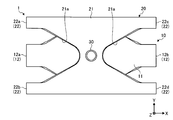
- FIG. 2 is a front view showing the configuration of the spring member according to the first embodiment.
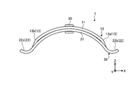
- FIG. 3 is a side view in the direction of arrow A in FIG. 4 is a side view in the direction of arrow B in FIG.
- FIG. 5 is a rear view showing the configuration of the spring member according to the first embodiment.
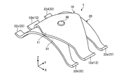
- FIG. 6 is a perspective view showing the configuration of the spring member according to the first embodiment.
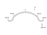
- FIG. 7 is a side view illustrating the configuration of the main part of the spring member according to the first embodiment, and is a diagram illustrating the configuration of the first member 10 according to the direction of arrow A in FIG. 2.
- the spring member 1 is formed using flat spring steel made of carbon tool steel (SK material), stainless steel (SUS), or the like.
- the spring member 1 includes a first member 10 (constituent member) formed by bending a predetermined direction (for example, the longitudinal direction), and a second member 20 (constituent member) formed by bending a predetermined direction (for example, the longitudinal direction). And a caulking member 30 that caulks and fixes the first member 10 and the second member 20 in an overlapped state.
- the first member 10 and the second member 20 are leaf springs curved along the main surface, and are laminated with their plate thickness directions aligned.
- the first member 10 and the second member 20 are joined by the caulking member 30 in a state where the first member 10 and the second member 20 are overlapped with the plate thickness direction aligned.
- the caulking member 30 is inserted into a through hole (not shown) penetrating in the plate thickness direction formed in the first member 10 and the second member 20 and then deformed by pressurizing the rivet having a convex shape.
- the first member 10 and the second member 20 are joined.
- each member a surface having a relatively large area is referred to as a “main surface”, and a surface continuous with the main surface is referred to as a “side surface”.
- the length in the direction (Y direction) perpendicular to the bending direction on the main surface is referred to as “width”.
- the first member 10 has a substantially rhombus shape formed on the outer edge (the shape in the XY plane in FIG. 2), and a base portion 11 having a curved shape along the main surface, Two first extending portions 12 a and 12 b (end portions that extend in opposite directions from the end portions closer to each other due to the curvature of the base portion 11 and are curved in a manner opposite to the curved manner of the base portion 11.
- the first extending portion 12 two bent portions that are provided between the base portion 11 and the first extending portion 12 and have a smaller radius of curvature than the radius of curvature of the base portion 11.
- the base 11 has a shape with a width that decreases toward an end that is continuous with the first extending portion 12.
- the curved shape of the base portion 11 is an arc shape having a center of curvature on one side with respect to the main surface facing in the plate thickness direction as viewed from the Y direction (FIG. 3).
- the second member 20 has a substantially H-shaped outer edge shape (a shape in the XY plane in FIG. 5), and is curved along the main surface with substantially the same radius of curvature as the base 11.
- the base portion 21 has a curved shape along the vertical direction of the H shape, and the slit 21a formed in the vertical direction has a large interval toward the end portion (toward the direction extending to the second extending portion 22). It has a tapered shape. In other words, the base portion 21 has a shape in which the width decreases toward the end portion continuous with the second extending portion 22.
- the thickness of the second member 20 is substantially equal to the thickness of the first member 10.
- the first member 10 and the second member 20 have bases 11 and 21 having the same radius of curvature, and the main surfaces of the first member 10 and the second member 20 are in contact with each other when stacked. Since the bent portion 13 is bent, for example, the first extending portion 12a is disposed between the second extending portions 22a and 22b, and the first extending portion 12a and the second extending portions 22a and 22b are arranged. Are arranged in the Y direction. As described above, in the spring member 1 according to the first embodiment, the plurality of extending portions of the respective constituent members (the first member 10 and the second member 20) do not overlap each other in the stacking direction of the plurality of constituent members. Is arranged.
- the end portions in the Z direction (negative direction) of the first extending portion 12 and the second extending portion 22 are located on the same plane P (see FIG. 4).
- the plane P is a pressed body (here, the first object to be pressed) of the first extension part 12 and the second extension part 22 on the side where the first extension part 12 and the second extension part 22 contact. It is a plane that passes through the tip of the extending portion (here, the second extending portion 22 of the second member 20) of the member having the base on the side closest to the pressing body 101).
- the first member 10 and the second member 20 have the same spring constant and elastic stroke.
- the base portion 11 is interposed between the second pressed body 103 and the second pressed body 103.
- the 1st extension part 12 and the 2nd extension part 22 contact the 1st to-be-pressed body 101, and apply a load.
- the first member 10 and the second member 20 are elastically deformed, and the first force 10 and the second member 20 are elastically deformed by the elastic force due to the elastic deformation. Pressure is applied to both the first pressed body 101 and the second pressed body 102.
- the stress from the pressed body is made uniform, and the first member 10 (first member 10)
- the spring constant of the one extending portion 12) can be reduced.
- the 2nd member 20 in order to make a taper shape from the center part of the base 21 to the 2nd extension part 22 with the slit 21a, a load is applied to the 1st to-be-pressed body 101 and the 2nd to-be-pressed body 102. The stress at the time can be made uniform.
- the first extending portion 11 is disposed between the second extending portions 22, and the first pressed body 101 is pressed by the first extending portion 11 and the second extending portion 22. Therefore, the surface pressure can be made uniform.
- the end portions in the Z direction (negative direction) of the first extending portion 12 and the second extending portion 22 are respectively located on the same plane P, and the first pressed body.
- the load from the first member 10 and the second member 20 is applied to the first pressed body 101 in a balanced manner.
- the second extending portion 22 of the second member 20 located on the first pressed body 101 side protrudes with respect to the plane P, and the second extending portion 22 comes before the first extending portion 12.
- the first member 10 When coming into contact with the first pressed body 101, the first member 10 is pushed up to the opposite side of the first pressed body 101 by the deformation of the second member 20 due to the contact with the first pressed body 101.
- the contact load applied to the first pressed body 101 by the first extending portion 12 becomes small, and the load may not be applied to the first pressed body 101 as the spring member 1 in a balanced manner.
- the conditions such as the same plate thickness as described above and the positions of the end portions of the first extension portion 12 and the second extension portion 22 with respect to the plane P are set. If satisfied, the radii of curvature of the base parts 11 and 21 can be freely designed, and can be appropriately designed according to the distance between the first pressed body 101 and the second pressed body 102.
- first member 10 and the second member 20 are configured as the spring member 1 integrated by the caulking member 30, it is not necessary to position the plurality of functional units for each functional unit, and the first unit 10 and the second member 20 serve as the pressing unit. It can be easily arranged between the first pressed body 101 and the second pressed body 102.
- the first portions 10 and 21 provided at the ends extending in a tapered shape. Since the 1 extension part 12 and the 2nd extension part 22 contacted the 1st to-be-pressed body 101 simultaneously, it is a surface pressure with respect to the 1st to-be-pressed body 101 and the 2nd to-be-pressed body 102. The distribution can be made uniform and pressed, and the elastic stroke of the spring member 1 with respect to the load can be lengthened.
- the tips of the first extending portion 12 and the second extending portion 22 in the Z direction (negative direction) are located on the same plane P, and the first extending portion 12 is.
- the second extending portion 22 has been described as being in contact with the first pressed body 101 at the same time.
- the member stacked on the opposite side of the first pressed body 101 (first embodiment)
- the first member 10) may be any member that contacts the first pressed body 101 at the same time or first, and the tip end of the first extending portion 12 in the Z direction is more negative than the plane P (negative).
- the first extending portion 12 may be in contact with the first pressed body 101 before the second extending portion 22.
- the member that comes into contact with the first pressed body 101 first is a member having a smaller number of extending portions in terms of realizing stable contact.
- the protrusion part which protrudes from one of the 1st member 10 or the 2nd member 20 is provided.
- the other member may be joined using the protruding portion as a rivet, or the first member 10 and the second member 20 may be joined by joining using an adhesive or welding. Good.
- the first extending portion 12 and the second extending portion 22 have been described as being bent in a manner opposite to the bending manner of the base portions 11 and 21, but the base portions 11 and 12 and It may be curved in the same manner.
- the curvature radii of the first extension part 12 and the second extension part 22 are smaller than the curvature radii of the base part 11 (bending part 13) and the base part 21.
- each structural member (the 1st member 10 and the 2nd member 20) is arrange
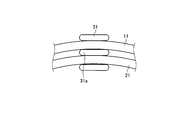
- FIG. 8 is a side view showing the configuration of the main part of the spring member according to the first modification of the first embodiment.
- the base portions 11 and 21 are described as being joined by the caulking member 30 while in contact with each other.
- the caulking member 31 is interposed between the base portions 11 and 21.
- the spacer portion 31a is provided.
- the spring member according to the first modification includes a caulking member 31 instead of the caulking member 30 of the spring member 1 described above.
- the caulking member 31 has a spacer portion 31a.
- the base parts 11 and 21 adjacent in the stacking direction are joined together with a space provided by the spacer part 31a. Thereby, the friction etc. which arise between the 1st member 10 and the 2nd member 20 can be reduced.
- this modification 1 replaces with the crimp member 31, and when joining the 1st member 10 and the 2nd member 20 by joining by the protrusion part mentioned above, joining by an adhesive agent, joining by welding etc., it is a spacer member. May be provided between the first member 10 and the second member 20.
- FIG. 9 is a perspective view showing the configuration of the spring member according to the second modification of the first embodiment.
- the first extending portion 12 and the second extending portion 22 have been described as having a uniform width.
- the first extending portion 14 having a different width is used.
- the 2nd extension part 23 is provided.
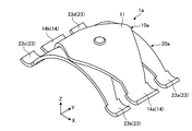
- the spring member 1a according to the second modification includes a first member 10a and a second member 20a.
- the first member 10a instead of the first extending portion 12 and the second extending portion 22 of the spring member 1 described above, the first member 10a includes the first extending portion 14, and the second member 20a is the second extending portion.
- the extending part 23 is provided.
- Each of the first extending portions 14 extends from the base portion 11 with a width larger than the width of the base portion 11.
- Each of the second extending portions 23 extends from the base portion 21 with a width larger than the width of the base portion 21.
- the load per unit area on the contact surface can be reduced. it can.
- FIG. 10 is a front view showing the configuration of the spring member according to the third modification of the first embodiment.
- the spring member 1 has been described as being formed by laminating the first member 10 and the second member 20, but is not limited to laminating two members, but a plurality of three or more members. May be laminated.
- the spring member 1b according to the third modification is formed by stacking three members (a first member 40, a second member 50, and a third member 60).
- the spring member 1b includes a first member 40 (constituent member) that is bent in a predetermined direction (for example, the longitudinal direction), and a second member 50 (constituent member) that is bent in a predetermined direction (for example, the longitudinal direction).
- a caulking member 32 that is fixed by caulking in a state where the third member 60 (constituent member) bent in a predetermined direction (for example, the longitudinal direction) and the first member 40, the second member 50, and the third member 60 are overlapped. And comprising.
- the first member 40, the second member 50, and the third member 60 are leaf springs that are curved along the main surface, and are laminated with their plate thickness directions aligned.
- the first member 40, the second member 50, and the third member 60 are joined by the caulking member 32 in a state where the first member 40, the second member 50, and the third member 60 are stacked with the plate thickness direction aligned.
- the caulking member 32 pressurizes after inserting the convex rivet into through holes (not shown) penetrating in the plate thickness direction formed in the first member 40, the second member 50, and the third member 60, respectively.
- the first member 40 has a base 41 that has a substantially rhombus shape (a shape in the XY plane in FIG. 10) and is curved along the main surface.
- Two first extending portions 42a and 42b (hereinafter simply referred to as first extending portions 42) that extend in opposite directions from the end portions on the sides closer to each other by bending and are bent in a manner opposite to the bending manner of the base portion 41.
- two bent portions 43a and 43b (referred to as bent portions 43) provided between the base portion 41 and the first extending portion 42 and having a smaller radius of curvature than the radius of curvature of the base portion 41.
- the base 41 has a shape with a width that decreases toward an end continuous with the first extending portion 42.
- the second member 50 has a substantially rhombus shape formed on the outer edge (the shape in the XY plane in FIG. 10), and a base 51 that is curved along the main surface, Two second extending portions 52 a and 52 b (hereinafter simply referred to as second extending portions 52) that extend in opposite directions from the end portions that are close to each other due to the bending and are curved in a manner opposite to the bending manner of the base portion 51. And two bent portions 53a and 53b (bent portions 53) provided between the base portion 51 and the second extending portion 52 and having a smaller radius of curvature than the radius of curvature of the base portion 51. There is also.
- the base 51 has a shape with a width that decreases toward an end that is continuous with the second extending portion 52.
- the thickness of the second member 50 is preferably substantially equal to the thickness of the first member 40.
- the third member 60 has a substantially H-shaped outer edge, and is curved along the main surface with substantially the same radius of curvature as the base 41, as in the second member 20 described above.
- Four third extending portions 62a that extend in opposite directions to each other from the base portion 61 having the shape and the end portions closer to each other due to the curvature of the base portion 61, and are curved in a manner opposite to the curved manner of the base portion 61, 62b, 62c, 62d (hereinafter also simply referred to as the third extending portion 62).
- the base 61 has a shape with a width that decreases toward an end that is continuous with the third extending portion 62.
- the third member 60 preferably has a thickness substantially equal to the thickness of the first member 40.
- the first member 40, the second member 50, and the third member 60 have bases 41, 51, and 61 that have the same radius of curvature, and the main surfaces come into contact with each other when stacked. Since the bent portion 43 of the first member 40 and the bent portion 53 of the second member 50 are bent, for example, the first extending portion 42a and the second extending portion 52a are connected to the third extending portion 62a, The first extending portion 42a, the second extending portion 52a, and the third extending portions 62a and 62b are arranged in the Y direction, arranged between 62b.
- first extending portion 42a, the second extending portion 52a, and the third extending portions 62a and 62b have the positional relationship and the width relationship between the end portions in the Z direction (negative direction) as described above. It is preferable. Specifically, the end portions in the Z direction (negative direction) of the first extending portion 42a, the second extending portion 52a, and the third extending portions 62a and 62b are on the same plane, or the second It is preferable that the positional relationship is such that the first extending portion 42a, the second extending portion 52a, and the third extending portions 62a and 62b come into contact with one pressed body 101 in this order.
- the width of the first extending portion 42a is D 4
- the width of the second extending portion 52a is D 5
- the width of the third extending portion 62a is D 61
- the width of the third extending portion 62b is D 62 .
- FIG. 11 is a side view showing the configuration of the main part of the spring member according to Modification 4 of Embodiment 1 of the present invention.
- the first member 10 has been described as having the bent portion 13, but in the fourth modification, the second member 20 b has the bent portion 25.
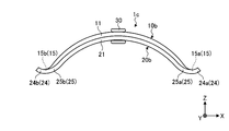
- the spring member 1c according to the fourth modification includes a first member 10b and a second member 20b.
- the first extending portion 15 is provided instead of the first extending portion 12 and the bent portion 13 of the first member 10 described above, and the second extending portion 22 of the second member 20 is replaced with the second extending portion 22.
- Two extending portions 24 and a bent portion 25 are provided.
- the first member 10b extends in the opposite direction from the base portion 11 and the end portions closer to each other due to the curvature of the base portion 11, and two first extensions that are curved in a manner opposite to the curved manner of the base portion 11. And an existing portion 15 (first extending portions 15a and 15b).
- the second member 20b extends from the end portion of the base portion 21 and the end portion of the base portion 21 in the opposite directions from the end portions closer to each other due to the bending of the base portion 21 and is opposite to the bending mode of the base portion 21.
- the four second extending portions 24 (only the second extending portions 24 a and 24 b are shown in FIG. 11) that are curved in the form are provided between the base portion 21 and the second extending portion 24, respectively.
- There are four bent portions 25 (only the bent portions 25a and 25b are shown in FIG. 11) having a larger radius of curvature than the radius of curvature.
- the base 21 Even if it is a case where the bending part 25 which has a larger curvature radius than this curvature radius is provided, the effect mentioned above can be acquired.
- the bent portion 25 may be bent in a manner opposite to the bending manner of the base portion 21.
- FIG. 12 is a schematic diagram illustrating a configuration of a main part of the power conversion device according to the second embodiment of the present invention.
- symbol is attached
- a power conversion device that is a pressing unit will be described as an application example of the spring member 1.
- the power conversion device 200 shown in FIG. 1 is a device that generates a drive current that flows to a travel motor for an electric vehicle, for example.
- the spring member 1 according to the first embodiment is provided, but the spring member according to the first to third modifications of the first embodiment may be used.
- the power conversion device 200 includes a semiconductor multilayer unit (first pressed body) 202 including semiconductor elements, a spring member 1 that presses the semiconductor multilayer unit 202 from one side surface, and the semiconductor multilayer unit 202 and the spring member 1. A flat contact plate 204 interposed therebetween, and a housing (second pressed body) 205 that accommodates the semiconductor laminated unit 202, the spring member 1, and the contact plate 204 are provided.
- the power conversion device 200 includes a control circuit and the like for controlling the semiconductor module 221 in addition to the illustration.
- the semiconductor lamination unit 202 has a structure in which the semiconductor modules 221 and the cooling pipes 222 are alternately laminated. In the case illustrated in FIG. 12, two semiconductor modules 221 are disposed between the cooling pipes 222 adjacent along the stacking direction.
- an IGBT element for supplying power and a flywheel diode element provided for smoothly rotating the motor are arranged between a pair of heat sinks and sealed with a resin so that the pair of heat sinks are exposed. Stopped and integrally molded.
- the cooling pipe 222 is a flat pipe having a refrigerant flow path inside.
- natural refrigerants such as water and ammonia, water mixed with ethylene glycol antifreeze, fluorocarbon refrigerants such as fluorinate, chlorofluorocarbon refrigerants such as HCFC123 and HFC134a, alcohols such as methanol and alcohol, etc.
- a cooling medium such as a system refrigerant or a ketone refrigerant such as acetone is circulated.
- the plurality of cooling pipes 222 are connected to each other via a connection pipe 223 extending along the stacking direction of the semiconductor stacking unit 202.
- a refrigerant introduction port 224 and a refrigerant discharge port 225 connected to the cooling pipe 222 arranged at the end portion are provided at the end portion of the connection pipe 223.
- the cooling pipe 222, the connecting pipe 223, the refrigerant inlet 224, and the refrigerant outlet 225 are realized using, for example, aluminum.
- the main surface 222 a of the cooling pipe 222 is in close contact with the heat radiating plate of the semiconductor module 221 by the pressing force from the spring member 1. Thereby, heat exchange can be performed between the semiconductor module 221 and the cooling pipe 222.
- the semiconductor lamination unit 202 can be uniformly pressed in the direction of lamination with a sufficient pressing force. Therefore, the cooling efficiency of the semiconductor stacked unit 202 by the cooling pipe 222 can be improved.
- FIG. 13 is a schematic diagram showing a configuration of a main part of the electric double layer capacitor according to the third embodiment of the present invention.
- symbol is attached
- an electric double layer capacitor that is a pressing unit will be described as an application example of the spring member 1.
- the electric double layer capacitor 250 includes a cell multilayer body (first pressed body) 252 including a plurality of package cells 251 and a spring member 1 that presses the cell multilayer body 252 from one side surface.
- a flat contact plate 254 interposed between the cell stack 252 and the spring member 1, and a housing (second pressed body to be accommodated) that accommodates the cell stack 252, the spring member 1, and the contact plate 254. ) 255.
- the electric double layer capacitor 250 has a connection terminal with an external circuit in addition to the illustration.
- the cell stack 252 is electrically connected to a connection terminal with an external circuit.
- the cell stack 252 is configured by stacking a plurality of package cells 251.
- Each package cell 251 includes an innermost layer and an outermost layer made of an insulating film, and includes a positive electrode collector electrode and a negative electrode collector electrode.
- a laminated body in which a plurality of collector electrodes are overlapped with each other through a separator is accommodated together with an electrolytic solution.
- the positive electrode terminal and the negative electrode terminal of each collector electrode are connected to the positive electrode collector electrode and the negative electrode collector electrode, respectively.
- the plurality of package cells 251 are connected in series by connecting the positive and negative electrode collectors of adjacent package cells 251 with connection terminals.
- the energy density per unit volume is reduced by pressing the cell laminate 252 of the electric double layer capacitor 250 in the lamination direction by the spring member 1 to limit the expansion of the polarizable electrode. It becomes possible to improve.
- the load applied between the first pressed body and the second pressed body can be increased by using the plurality of spring members 1 stacked and stacked. it can.
- the power conversion device is taken as an example of a pressing unit that needs to be pressed by the spring member 1, and in the above-described third embodiment, the electric double layer capacitor needs to be pressed by the spring member 1.
- the pressing unit to which the spring member 1 according to Embodiment 1 is applied has the spring member 1 disposed between the first pressed body and the second pressed body, Any member may be used as long as the first pressed member and the second pressed member are pressed by the spring member 1.
- the present invention can include various embodiments not described herein, and various design changes and the like can be made without departing from the technical idea specified by the claims. Is possible.
- the first modification may be combined with the third modification of the first embodiment, and the caulking member 32 may be provided with a spacer portion so that adjacent members are separated in the stacking direction.
- the pressing structure and the pressing unit according to the present invention are suitable for equalizing the surface pressure distribution and pressing and extending the elastic stroke with respect to the load.
Landscapes
- Engineering & Computer Science (AREA)
- General Engineering & Computer Science (AREA)
- Mechanical Engineering (AREA)
- Power Engineering (AREA)
- Springs (AREA)
- Cooling Or The Like Of Semiconductors Or Solid State Devices (AREA)
- Fuel Cell (AREA)
Abstract
本発明に係る押圧構造は、第1の被押圧体と第1の被押圧体に対向する第2の被押圧体との間に配置され、第1の被押圧体及び第2の被押圧体に対して押圧する押圧構造であって、板状の部材からなり、湾曲した主面を有する基部と、基部の端部からそれぞれ延びる複数の延在部とを有する複数の構成部材を積層してなるばね部材を備え、ばね部材は、基部側で一方の被押圧体と接触するとともに、延在部が他方の被押圧体と接触し、各構成部材の延在部が、接触対象の被押圧体に接触する。
Description
本発明は、押圧構造及び押圧ユニットに関する。
二つの被押圧体の間に設置され、その一方もしくは双方を加圧して押圧するばね部材が知られている。ばね部材は、様々な装置に用いられている。例えば、半導体モジュールと該半導体モジュールを冷却する冷却管とを交互に積層することによって構成される積層構造を有する電力変換装置(押圧ユニット)が知られている(例えば、特許文献1を参照)。
この電力変換装置は、半導体モジュールと冷却管との積層方向の端部に、積層方向に沿った押圧力を発生するばね部材と、このばね部材と積層構造との間に設けられ、積層方向に均一な押圧力を発生させるための当接プレートとを備える。このような構成を有する電力変換装置によれば、ばね部材の押圧力によって隣接する半導体モジュールと冷却管とが密着するため、半導体モジュールを十分に冷却することができる。
ところで、上述したような押圧用途のばね部材では、押圧対象の公差等を吸収するため、荷重に対する弾性ストロークが長いことが重要になるが、同時に、均一な面圧分布(=低面圧)で押圧することが求められる。弾性ストロークを長くするための手法として、複数枚の板状のばね部材をストローク方向に重ねる手法が挙げられる。しかしながら、ばね部材間の摩擦によって発生するヒステリシス(往路・復路での荷重差)や、アッセンブリの複雑さが問題となり、何枚も重ねることができず、弾性ストロークを長くできる範囲が限られていた。
弾性ストロークを長くする他の手法として、押圧対象との接触側を先細り形状とすることで、応力を均一化して弾性ストロークを長くする手法が知られている。この手法では、先端部の幅がゼロに近づくほど応力均一化の効果が高い。しかしながら、この手法を併用する場合、先細りとなっている先端部が押圧対象と接触することになるため、接触面積の減少により面圧が増加してしまうという問題があった。
本発明は、上記に鑑みてなされたものであって、面圧分布を均一化して押圧するとともに、荷重に対する弾性ストロークを長くすることができる押圧構造及び押圧ユニットを提供することを目的とする。
上述した課題を解決し、目的を達成するために、本発明に係る押圧構造は、第1の被押圧体と前記第1の被押圧体に対向する第2の被押圧体との間に配置され、前記第1の被押圧体及び前記第2の被押圧体に対して押圧する押圧構造であって、板状の部材からなり、湾曲した主面を有する基部と、前記基部の端部からそれぞれ延びる複数の延在部とを有する複数の構成部材を積層してなるばね部材を備え、前記ばね部材は、前記基部側で一方の被押圧体と接触するとともに、前記延在部が他方の被押圧体と接触し、各構成部材の前記延在部が、接触対象の被押圧体に接触することを特徴とする。
また、本発明に係る押圧構造は、上記の発明において、各構成部材の前記複数の延在部は、前記複数の構成部材の積層方向において互いに重ならない位置に配置されていることを特徴とする。
また、本発明に係る押圧構造は、上記の発明において、前記基部は、前記延在部に連なる側にいくにしたがって幅が小さくなることを特徴とする。
また、本発明に係る押圧構造は、上記の発明において、前記第1及び第2の被押圧体から荷重が加わっていない状態において、各構成部材の前記延在部のうち、該延在部が接触する側の被押圧体に対して最も近い側に前記基部を有する構成部材の延在部の先端を通過する平面に対し、他の構造部材の延在部の先端が、前記平面上、又は該平面から突出していることを特徴とする。
また、本発明に係る押圧構造は、上記の発明において、各構成部材は、板厚が同じであることを特徴とする。
また、本発明に係る押圧構造は、上記の発明において、積層方向で隣り合う構成部材が、離間して接合されていることを特徴とする。
また、本発明に係る押圧構造は、上記の発明において、前記複数の構成部材のうち、前記延在部が接触する側の被押圧体に対して最も近い側に前記基部を有する構成部材以外の構成部材は、前記基部と前記延在部との間に設けられ、前記基部の曲率半径よりも小さい曲率半径で屈曲する屈曲部を有することを特徴とする。
また、本発明に係る押圧ユニットは、第1の被押圧体と、前記第1の被押圧体に対向配置される第2の被押圧体と、前記第1の被押圧体と前記第2の被押圧体との間に配置され、前記第1の被押圧体及び前記第2の被押圧体に対して押圧する上記の発明に係る押圧構造と、を備えることを特徴とする。
本発明によれば、面圧分布を均一化して押圧するとともに、荷重に対する弾性ストロークを長くすることができるという効果を奏する。
以下の説明では、本発明を実施するための形態(以下、「実施の形態」という)として、ばね部材を用いた押圧ユニットについて説明する。また、この実施の形態により、この発明が限定されるものではない。さらに、図面の記載において、同一部分には同一の符号を付している。さらにまた、図面は、模式的なものであり、各部材の厚みと幅との関係、各部材の比率等は、現実と異なることに留意する必要がある。また、図面の相互間においても、互いの寸法や比率が異なる部分が含まれている。なお、同一の形状とは、設計上同一の形状をなすものであり、製造上の誤差を含む。
(実施の形態1)
図1は、本発明の実施の形態1に係るばね部材を用いた押圧ユニットを模式的に示す側面図である。本発明の実施の形態1に係る押圧構造100は、対向する第1の被押圧体101と第2の被押圧体102の間にばね部材1を配置する。本実施の形態1による押圧ユニットは、対向する第1の被押圧体101と第2の被押圧体102との間に押圧構造100を配置する。押圧構造100は、ばね部材1の弾性力により、第1の被押圧体101と第2の被押圧体102の双方に対して圧力を加える。第2の被押圧体102とばね部材1との間には、ばね部材1の荷重を第2の被押圧体102に伝える加圧部材103が設けられている。加圧部材103は、ばね部材1と接触する側の面が、一様な平面を形成しているものであってもよいし、該ばね部材1の形状に応じて一部が凹形状をなすもの、例えば後述するカシメ部材30の形状に対応する凹部が形成されたものであってもよい。なお、ばね部材1が加圧部材103を介して間接的に接触するものに限らず、加圧部材103を設けずに、ばね部材1が直接第2の被押圧体102に接触するものであってもよい。また、ばね部材1は、第1の被押圧体101についても、直接接触するものであってもよいし、加圧部材を介して間接的に接触するものであってもよい。
図1は、本発明の実施の形態1に係るばね部材を用いた押圧ユニットを模式的に示す側面図である。本発明の実施の形態1に係る押圧構造100は、対向する第1の被押圧体101と第2の被押圧体102の間にばね部材1を配置する。本実施の形態1による押圧ユニットは、対向する第1の被押圧体101と第2の被押圧体102との間に押圧構造100を配置する。押圧構造100は、ばね部材1の弾性力により、第1の被押圧体101と第2の被押圧体102の双方に対して圧力を加える。第2の被押圧体102とばね部材1との間には、ばね部材1の荷重を第2の被押圧体102に伝える加圧部材103が設けられている。加圧部材103は、ばね部材1と接触する側の面が、一様な平面を形成しているものであってもよいし、該ばね部材1の形状に応じて一部が凹形状をなすもの、例えば後述するカシメ部材30の形状に対応する凹部が形成されたものであってもよい。なお、ばね部材1が加圧部材103を介して間接的に接触するものに限らず、加圧部材103を設けずに、ばね部材1が直接第2の被押圧体102に接触するものであってもよい。また、ばね部材1は、第1の被押圧体101についても、直接接触するものであってもよいし、加圧部材を介して間接的に接触するものであってもよい。
図2は、本実施の形態1に係るばね部材の構成を示す正面図である。図3は、図2の矢視A方向の側面図である。図4は、図2の矢視B方向の側面図である。図5は、本実施の形態1に係るばね部材の構成を示す背面図である。図6は、本実施の形態1に係るばね部材の構成を示す斜視図である。図7は、本実施の形態1に係るばね部材の要部の構成を示す側面図であって、図2の矢視A方向に応じた第1部材10の構成を示す図である。ばね部材1は、炭素工具鋼鋼材(SK材)、ステンレス鋼(SUS)などからなる平板状のばね鋼を用いて形成される。
ばね部材1は、所定の方向(例えば長手方向)を屈曲させてなる第1部材10(構成部材)と、所定の方向(例えば長手方向)を屈曲させてなる第2部材20(構成部材)と、第1部材10及び第2部材20を重ねた状態でカシメて固定するカシメ部材30と、を備える。
第1部材10及び第2部材20は、主面に沿って湾曲した板ばねであって、互いの板厚方向を揃えて積層されている。第1部材10及び第2部材20は、板厚方向を揃えて重ねられた状態で、カシメ部材30によって接合される。カシメ部材30は、凸状をなすリベットを、第1部材10及び第2部材20に形成された板厚方向に貫通する貫通孔(図示せず)に挿通後、加圧して変形させることによって、第1部材10及び第2部材20を接合する。以下、各部材において、相対的に面積の広い面を「主面」、主面に連なる面を「側面」という。また、各部材において、主面における湾曲方向と直交する方向(Y方向)の長さを「幅」という。
第1部材10は、図2に示す正面図において外縁のなす形状(図2のXY平面における形状)が略ひし形状をなし、主面に沿って湾曲した形状をなす基部11と、基部11の端部であって、基部11の湾曲により互いに近づく側の端部から互いに反対方向にそれぞれ延びるとともに、基部11の湾曲態様とは逆の態様で湾曲する二つの第1延在部12a,12b(以下、単に第1延在部12ということもある)と、基部11と第1延在部12との間にそれぞれ設けられ、基部11の曲率半径と比して曲率半径が小さい二つの屈曲部13a,13b(以下、単に屈曲部13ということもある)を有する。基部11は、第1延在部12に連なる端部に向けて幅が小さくなる形状をなしている。なお、本実施の形態1において、基部11の湾曲形状は、Y方向(図3)からみて、板厚方向で対向する主面に対して一方に曲率中心を有する弧状である。
第2部材20は、図5に示す背面図において外縁のなす形状(図5のXY平面における形状)が略H字形状をなし、基部11と略同一の曲率半径で主面に沿って湾曲した形状をなす基部21と、基部21の湾曲により互いに近づく側の端部から互いに反対方向にそれぞれ延びるとともに、基部21の湾曲態様とは逆の態様で湾曲する四つの第2延在部22a,22b,22c,22d(以下、単に第2延在部22ということもある)と、を有する。基部21は、H字の上下方向に沿って湾曲した形状をなし、上下方向に形成されるスリット21aが、端部に向けて(第2延在部22に連なる方向に向けて)間隔が大きくなるテーパ状をなしている。換言すれば、基部21は、第2延在部22に連なる端部に向けて幅が小さくなる形状をなしている。第2部材20は、厚さが、第1部材10の厚さと略同等である。
ばね部材1では、第1部材10と第2部材20とは、基部11,21が同一の曲率半径を有しており、積層された際に主面同士が接触するものの、第1部材10の屈曲部13により屈曲しているため、例えば、第1延在部12aが、第2延在部22a,22bの間に配置されて、第1延在部12a及び第2延在部22a,22bがY方向で並んだ構成となっている。このように、本実施の形態1に係るばね部材1は、各構成部材(第1部材10及び第2部材20)の複数の延在部が、複数の構成部材の積層方向において互いに重ならない位置に配置されている。
また、ばね部材1では、第1延在部12及び第2延在部22のZ方向(負の方向)の端部は、同一の平面P(図4参照)上に位置している。ばね部材1は、第1の被押圧体101と接触する際、第1延在部12と第2延在部22とが、同時に接触する。この平面Pは、第1延在部12および第2延在部22のうち、この第1延在部12および第2延在部22が接触する側の被押圧体(ここでは第1の被押圧体101)に対して最も近い側に基部を有する部材の延在部(ここでは第2部材20の第2延在部22)の先端を通過する平面である。
また、ばね部材1では、第1延在部12aの幅をD1(図4参照)、第2延在部22aの幅をD2及び第2延在部22bの幅をD3としたとき、D2=D3、及びD1=D2+D3の関係を満たしている。このため、第1部材10及び第2部材20は、ばね定数及び弾性ストロークは同一である。
ばね部材1は、図1に示すように、第1の被押圧体101と第2の被押圧体102との間に配置されると、基部11が加圧部材103を介して第2の被押圧体102に荷重を加えるとともに、第1延在部12及び第2延在部22が第1の被押圧体101と接触して荷重を加える。第1の被押圧体101と第2の被押圧体102との間の距離を小さくしていくと、第1部材10及び第2部材20が弾性変形し、該弾性変形による弾性力によって、第1の被押圧体101と第2の被押圧体102の双方に対して圧力を加える。
ここで、上述したように、第1部材10では、基部11の中央部から第1延在部12にかけて先細な形状をなすため、被押圧体からの応力を均一化し、第1部材10(第1延在部12)が有するばね定数を低減することができる。また、第2部材20では、スリット21aによって基部21の中央部から第2延在部22にかけて先細な形状をなすため、第1の被押圧体101及び第2の被押圧体102に荷重を加える際の応力を均一化することができる。さらに、ばね部材1において、第2延在部22の間に第1延在部11を配置して、第1延在部11および第2延在部22によって第1の被押圧体101を押圧するため、面圧を均一化することができる。
また、ばね部材1では、第1延在部12及び第2延在部22のZ方向(負の方向)の端部は、それぞれが同一の平面P上に位置し、第1の被押圧体101と接触する際、第1延在部12と第2延在部22とが、同時に接触するため、第1部材10及び第2部材20による荷重を第1の被押圧体101にバランスよく加えることができる。例えば、第1の被押圧体101側に位置する第2部材20の第2延在部22が平面Pに対して突出し、該第2延在部22が第1延在部12よりも先に第1の被押圧体101に接触する場合、第1の被押圧体101との接触による第2部材20の変形によって、第1部材10が第1の被押圧体101側と反対側に押し上げられ、第1延在部12による第1の被押圧体101への接触荷重が小さくなってしまい、ばね部材1として第1の被押圧体101にバランスよく荷重を加えることができない場合がある。
第1部材10及び第2部材20において、上述したような、板厚が同一であることや、平面Pに対する第1延在部12及び第2延在部22の端部の位置などの条件を満たせば、基部11,21の曲率半径を自由に設計でき、第1の被押圧体101と第2の被押圧体102の間隔に応じて、適宜設計することが可能である。
また、第1部材10及び第2部材20は、カシメ部材30によって一体化されたばね部材1として構成しているため、複数の機能部の位置決めを機能部ごとに行う必要がなく、押圧ユニットとして第1の被押圧体101及び第2の被押圧体102の間に容易に配置することができる。
上述した実施の形態1によれば、積層することでばね部材1を構成する第1部材10及び第2部材20において、基部11,21の先細な形状をなして延びる端部に設けられた第1延在部12及び第2延在部22が、第1の被押圧体101に同時に接触するようにしたので、第1の被押圧体101及び第2の被押圧体102に対して面圧分布を均一化して押圧するとともに、荷重に対するばね部材1の弾性ストロークを長くすることができる。
なお、上述した実施の形態1では、第1延在部12及び第2延在部22のZ方向(負の方向)の先端は、同一の平面P上に位置し、第1延在部12及び第2延在部22が、第1の被押圧体101に同時に接触するものとして説明したが、第1の被押圧体101側とは反対側に積層されている部材(本実施の形態1では第1部材10)が、同時か先に第1の被押圧体101に接触するものであればよく、第1延在部12のZ方向の先端が、平面PよりもZ方向(負の方向)に突出し、第1延在部12が、第2延在部22よりも先に第1の被押圧体101に接触するものであってもよい。また、第1の被押圧体101に対して先に接触する部材は、延在部の数が少ない方の部材であることが、安定した接触を実現するという点で好ましい。
また、上述した実施の形態1では、カシメ部材30により第1部材10及び第2部材20を接合するものとして説明したが、第1部材10又は第2部材20の一方から突出する突出部を設け、該突出部をリベットとして他方の部材を接合するものであってもよいし、接着剤による接合や、溶接等による接合によって、第1部材10及び第2部材20を接合するものであってもよい。
また、上述した実施の形態1では、第1延在部12及び第2延在部22が、基部11,21の湾曲態様と逆の態様で湾曲するものとして説明したが、基部11,12と同じ態様で湾曲するものであってもよい。この場合、第1延在部12及び第2延在部22における曲率半径は、基部11(屈曲部13)及び基部21の曲率半径よりも小さい。
また、上述した実施の形態1では、各構成部材(第1部材10及び第2部材20)の複数の延在部が、複数の構成部材の積層方向において互いに重ならない位置に配置されているものとして説明したが、一部が重なる位置に配置されていてもよい。
(実施の形態1の変形例1)
図8は、本実施の形態1の変形例1に係るばね部材の要部の構成を示す側面図である。上述した実施の形態1では、基部11,21を接触した状態で、カシメ部材30によって接合されるものとして説明したが、本変形例1では、カシメ部材31が、基部11,21の間に介在するスペーサ部31aを有する。本変形例1に係るばね部材は、上述したばね部材1のカシメ部材30に代えて、カシメ部材31を備える。カシメ部材31は、スペーサ部31aを有する。積層方向で隣り合う基部11,21は、スペーサ部31aによって間隔が設けられた状態で接合される。これにより、第1部材10と第2部材20との間に生じる摩擦等を低減することができる。
図8は、本実施の形態1の変形例1に係るばね部材の要部の構成を示す側面図である。上述した実施の形態1では、基部11,21を接触した状態で、カシメ部材30によって接合されるものとして説明したが、本変形例1では、カシメ部材31が、基部11,21の間に介在するスペーサ部31aを有する。本変形例1に係るばね部材は、上述したばね部材1のカシメ部材30に代えて、カシメ部材31を備える。カシメ部材31は、スペーサ部31aを有する。積層方向で隣り合う基部11,21は、スペーサ部31aによって間隔が設けられた状態で接合される。これにより、第1部材10と第2部材20との間に生じる摩擦等を低減することができる。
なお、本変形例1において、カシメ部材31に代えて、上述した突出部による接合や、接着剤による接合、溶接等による接合によって第1部材10及び第2部材20を接合する場合は、スペーサ部材を第1部材10及び第2部材20の間に設ければよい。
(実施の形態1の変形例2)
図9は、本実施の形態1の変形例2に係るばね部材の構成を示す斜視図である。上述した実施の形態1では、第1延在部12及び第2延在部22が一様な幅を有するものとして説明したが、本変形例2では、異なる幅を有する第1延在部14及び第2延在部23を備える。本変形例2に係るばね部材1aは、第1部材10a及び第2部材20aを備える。本変形例2では、上述したばね部材1の第1延在部12及び第2延在部22に代えて、第1部材10aが第1延在部14を備え、第2部材20aが第2延在部23を備える。
図9は、本実施の形態1の変形例2に係るばね部材の構成を示す斜視図である。上述した実施の形態1では、第1延在部12及び第2延在部22が一様な幅を有するものとして説明したが、本変形例2では、異なる幅を有する第1延在部14及び第2延在部23を備える。本変形例2に係るばね部材1aは、第1部材10a及び第2部材20aを備える。本変形例2では、上述したばね部材1の第1延在部12及び第2延在部22に代えて、第1部材10aが第1延在部14を備え、第2部材20aが第2延在部23を備える。
第1延在部14(第1延在部14a,14b)は、各々が、基部11から、該基部11の幅よりも大きな幅で延びる。第2延在部23(第2延在部23a~23d)は、各々が、基部21から、該基部21の幅よりも大きな幅で延びる。
本変形例2によれば、第1の被押圧体101と接触する第1延在部14及び第2延在部23を大きく形成したので、接触面における単位面積あたりの荷重を小さくすることができる。
(実施の形態1の変形例3)
図10は、本実施の形態1の変形例3に係るばね部材の構成を示す正面図である。上述した実施の形態1では、ばね部材1が、第1部材10及び第2部材20を積層してなるものとして説明したが、二つの部材を積層するものに限らず、三以上の複数の部材を積層してもよい。本変形例3に係るばね部材1bは、三つの部材(第1部材40、第2部材50及び第3部材60)を積層してなる。
図10は、本実施の形態1の変形例3に係るばね部材の構成を示す正面図である。上述した実施の形態1では、ばね部材1が、第1部材10及び第2部材20を積層してなるものとして説明したが、二つの部材を積層するものに限らず、三以上の複数の部材を積層してもよい。本変形例3に係るばね部材1bは、三つの部材(第1部材40、第2部材50及び第3部材60)を積層してなる。
ばね部材1bは、所定の方向(例えば長手方向)を屈曲させてなる第1部材40(構成部材)と、所定の方向(例えば長手方向)を屈曲させてなる第2部材50(構成部材)と、所定の方向(例えば長手方向)を屈曲させてなる第3部材60(構成部材)と、第1部材40、第2部材50及び第3部材60を重ねた状態でカシメて固定するカシメ部材32と、を備える。
第1部材40、第2部材50及び第3部材60は、主面に沿って湾曲した板ばねであって、互いの板厚方向を揃えて積層されている。第1部材40、第2部材50及び第3部材60は、板厚方向を揃えて重ねられた状態で、カシメ部材32によって接合される。カシメ部材32は、凸状をなすリベットを、第1部材40、第2部材50及び第3部材60にそれぞれ形成された板厚方向に貫通する貫通孔(図示せず)に挿通後、加圧して変形させることによって、第1部材40、第2部材50及び第3部材60を接合する。
第1部材40は、図10に示す正面図において外縁のなす形状(図10のXY平面における形状)が略ひし形状をなし、主面に沿って湾曲した形状をなす基部41と、基部41の湾曲により互いに近づく側の端部から互いに反対方向にそれぞれ延びるとともに、基部41の湾曲態様とは逆の態様で湾曲する二つの第1延在部42a,42b(以下、単に第1延在部42ということもある)と、基部41と第1延在部42との間にそれぞれ設けられ、基部41の曲率半径と比して曲率半径が小さい二つの屈曲部43a,43b(屈曲部43ということもある)を有する。基部41は、第1延在部42に連なる端部に向けて幅が小さくなる形状をなしている。
第2部材50は、図10に示す正面図において外縁のなす形状(図10のXY平面における形状)が略ひし形状をなし、主面に沿って湾曲した形状をなす基部51と、基部51の湾曲により互いに近づく側の端部から互いに反対方向にそれぞれ延びるとともに、基部51の湾曲態様とは逆の態様で湾曲する二つの第2延在部52a,52b(以下、単に第2延在部52ということもある)と、基部51と第2延在部52との間にそれぞれ設けられ、基部51の曲率半径と比して曲率半径が小さい二つの屈曲部53a,53b(屈曲部53ということもある)を有する。基部51は、第2延在部52に連なる端部に向けて幅が小さくなる形状をなしている。第2部材50は、厚さが、第1部材40の厚さと略同等であることが好ましい。
第3部材60は、図10に示す正面図において、上述した第2部材20と同様、外縁のなす形状が略H字形状をなし、基部41と略同一の曲率半径で主面に沿って湾曲した形状をなす基部61と、基部61の湾曲により互いに近づく側の端部から互いに反対方向にそれぞれ延びるとともに、基部61の湾曲態様とは逆の態様で湾曲する四つの第3延在部62a,62b,62c,62d(以下、単に第3延在部62ということもある)と、を有する。基部61は、第3延在部62に連なる端部に向けて幅が小さくなる形状をなしている。第3部材60は、厚さが、第1部材40の厚さと略同等であることが好ましい。
ばね部材1bでは、第1部材40、第2部材50及び第3部材60は、基部41,51,61が同一の曲率半径を有しており、積層された際に主面同士が接触するものの、第1部材40の屈曲部43、及び第2部材50の屈曲部53により屈曲しているため、例えば、第1延在部42a及び第2延在部52aが、第3延在部62a,62bの間に配置されて、第1延在部42a、第2延在部52a及び第3延在部62a,62bがY方向で並んだ構成となっている。
また、上述したような第1延在部42a、第2延在部52a及び第3延在部62a,62bのZ方向(負の方向)の端部の位置関係や、幅の関係を有していることが好ましい。具体的には、第1延在部42a、第2延在部52a及び第3延在部62a,62bのZ方向(負の方向)の端部が、同一の平面上にあるか、又は第1の被押圧体101に対して、第1延在部42a、第2延在部52a、第3延在部62a,62bの順で接触するような位置関係であることが好ましい。また、第1延在部42aの幅をD4、第2延在部52aの幅をD5、第3延在部62aの幅をD61、第3延在部62bの幅をD62としたとき、D61=D62、及びD4=D5=D61+D62の関係を満たしていることが好ましい。
(実施の形態1の変形例4)
図11は、本発明の実施の形態1の変形例4に係るばね部材の要部の構成を示す側面図である。上述した実施の形態1では、第1部材10が屈曲部13を有するものとして説明したが、本変形例4では、第2部材20bが屈曲部25を有する。本変形例4に係るばね部材1cは、第1部材10b及び第2部材20bを備える。本変形例4では、上述した第1部材10の第1延在部12及び屈曲部13に代えて第1延在部15を備え、第2部材20の第2延在部22に代えて第2延在部24および屈曲部25を備える。
図11は、本発明の実施の形態1の変形例4に係るばね部材の要部の構成を示す側面図である。上述した実施の形態1では、第1部材10が屈曲部13を有するものとして説明したが、本変形例4では、第2部材20bが屈曲部25を有する。本変形例4に係るばね部材1cは、第1部材10b及び第2部材20bを備える。本変形例4では、上述した第1部材10の第1延在部12及び屈曲部13に代えて第1延在部15を備え、第2部材20の第2延在部22に代えて第2延在部24および屈曲部25を備える。
第1部材10bは、上述した基部11と、基部11の湾曲により互いに近づく側の端部から互いに反対方向にそれぞれ延びるとともに、基部11の湾曲態様とは逆の態様で湾曲する二つの第1延在部15(第1延在部15a,15b)と、を有する。
第2部材20bは、上述した基部21と、基部21の端部であって、基部21の湾曲により互いに近づく側の端部から互いに反対方向にそれぞれ延びるとともに、基部21の湾曲態様とは逆の態様で湾曲する四つの第2延在部24(図11では、第2延在部24a,24bのみを図示)と、基部21と第2延在部24との間にそれぞれ設けられ、基部21の曲率半径と比して曲率半径が大きい四つの屈曲部25(図11では、屈曲部25a,25bのみを図示)を有する。
本変形例4のように、第1および第2延在部が接触する側の被押圧体に対して最も近い側に基部を有する部材(本変形例4では第2部材20b)において、基部21の曲率半径よりも大きい曲率半径を有する屈曲部25を設けるようにした場合であっても、上述した効果を得ることができる。なお、第2部材20bにおいて、屈曲部25を、基部21の湾曲態様とは逆の態様で湾曲させるようにしてもよい。
(実施の形態2)
つぎに、本発明の実施の形態2について説明する。図12は、本発明の実施の形態2による電力変換装置の要部の構成を示す模式図である。なお、図1等で上述した構成要素と同じ構成要素には同じ符号を付してある。本実施の形態2では、ばね部材1の適用例として、押圧ユニットである電力変換装置を説明する。同図に示す電力変換装置200は、例えば、電気自動車用の走行モータに流す駆動電流を生成する装置である。なお、以下の例では、上述の実施の形態1のばね部材1を備えたものとして説明するが、実施の形態1の変形例1~3に係るばね部材を用いてもよい。
つぎに、本発明の実施の形態2について説明する。図12は、本発明の実施の形態2による電力変換装置の要部の構成を示す模式図である。なお、図1等で上述した構成要素と同じ構成要素には同じ符号を付してある。本実施の形態2では、ばね部材1の適用例として、押圧ユニットである電力変換装置を説明する。同図に示す電力変換装置200は、例えば、電気自動車用の走行モータに流す駆動電流を生成する装置である。なお、以下の例では、上述の実施の形態1のばね部材1を備えたものとして説明するが、実施の形態1の変形例1~3に係るばね部材を用いてもよい。
電力変換装置200は、半導体素子を含む半導体積層ユニット(第1の被押圧体)202と、一方の側面から半導体積層ユニット202を押圧するばね部材1と、半導体積層ユニット202とばね部材1との間に介在する平板状の当接板204と、半導体積層ユニット202、ばね部材1及び当接板204を収容する筐体(第2の被押圧体)205とを備える。電力変換装置200は、図示した以外にも、半導体モジュール221を制御する制御回路等を有する。
半導体積層ユニット202は、半導体モジュール221と冷却管222とを交互に積層した構造を有する。図12に示す場合、積層方向に沿って隣接する冷却管222の間に二個の半導体モジュール221が配置される。
半導体モジュール221は、電力供給用のIGBT素子と、モータを円滑に回転させるために設けられるフライホイールダイオード素子とを一対の放熱板の間に配置し、その一対の放熱板が露出するように樹脂によって封止されて一体成形されている。
冷却管222は、内部に冷媒流路を有する扁平な形状の管である。この冷媒流路には、例えば水やアンモニア等の自然冷媒、エチレングリコール系の不凍液を混入した水、フロリナート等のフッ化炭素系冷媒、HCFC123、HFC134a等のフロン系冷媒、メタノール、アルコール等のアルコール系冷媒、又はアセトン等のケトン系冷媒等の冷却媒体を流通させる。
複数の冷却管222は、半導体積層ユニット202の積層方向に沿って延びる連結パイプ223を介して相互に連結している。連結パイプ223の端部には、その端部に配された冷却管222に接続する冷媒導入口224及び冷媒排出口225が設けられている。冷却管222、連結パイプ223、冷媒導入口224及び冷媒排出口225は、例えばアルミニウムを用いて実現される。
冷却管222の主面222aは、ばね部材1からの押圧力によって半導体モジュール221の放熱板と密着している。これにより、半導体モジュール221と冷却管222との間で熱交換を行うことができる。
上述した実施の形態2によれば、ばね部材1を用いることにより、半導体積層ユニット202を、十分な押圧力で面内均一にその積層方向に押圧することができる。よって、冷却管222による半導体積層ユニット202の冷却効率を向上させることができる。
(実施の形態3)
つぎに、本発明の実施の形態3について説明する。図13は、本発明の実施の形態3による電気二重層キャパシタの要部の構成を示す模式図である。なお、図1等で上述した構成要素と同じ構成要素には同じ符号を付してある。本実施の形態3では、ばね部材1の適用例として、押圧ユニットである電気二重層キャパシタを説明する。なお、以下の例では、上述の実施の形態1のばね部材1を備えたものとして説明するが、実施の形態1の変形例1~3に係るばね部材を用いてもよい。
つぎに、本発明の実施の形態3について説明する。図13は、本発明の実施の形態3による電気二重層キャパシタの要部の構成を示す模式図である。なお、図1等で上述した構成要素と同じ構成要素には同じ符号を付してある。本実施の形態3では、ばね部材1の適用例として、押圧ユニットである電気二重層キャパシタを説明する。なお、以下の例では、上述の実施の形態1のばね部材1を備えたものとして説明するが、実施の形態1の変形例1~3に係るばね部材を用いてもよい。
本発明の実施の形態3による電気二重層キャパシタ250は、複数のパッケージセル251を含むセル積層体(第1の被押圧体)252と、一方の側面からセル積層体252を押圧するばね部材1と、セル積層体252とばね部材1との間に介在する平板状の当接板254と、セル積層体252、ばね部材1及び当接板254を収容する筐体(第2の被押圧体)255とを備える。電気二重層キャパシタ250は、図示した以外にも、外部回路との接続端子等を有する。セル積層体252は外部回路との接続端子に電気的に接続される。
セル積層体252は、複数のパッケージセル251を積層して構成される。それぞれのパッケージセル251は、最内層と最外層とが絶縁性フィルムで構成され、正極集電極と負極集電極とを備える。各パッケージセル251の内部には、セパレータを介して複数の集電極を重ね合わせた積層体が電解液とともに収容される。各集電極の正極端子と負極端子がそれぞれ正極集電極と負極集電極に接続される。複数のパッケージセル251は、隣接するパッケージセル251の正極集電極と負極集電極とを接続端子で連結して、直列に接続される。
上述した実施の形態3によれば、ばね部材1により電気二重層キャパシタ250のセル積層体252をその積層方向に押圧して分極性電極の膨張を制限することにより、単位体積当たりのエネルギー密度を向上することが可能となる。
上述した実施の形態2,3において、複数のばね部材1を重ね合わせて積層して用いることにより、第1の被押圧体と第2の被押圧体との間に加わる荷重を大きくすることができる。
また、上述の実施の形態2では、電力変換装置をばね部材1による押圧が必要な押圧ユニットの例としてあげ、上述の実施の形態3では、電気二重層キャパシタをばね部材1による押圧が必要な押圧ユニットの例としてあげたが、実施の形態1に係るばね部材1を適用する押圧ユニットは、第1の被押圧体と第2の被押圧体との間にばね部材1を配置して、第1の被押圧体と第2の被押圧体とをばね部材1により押圧するものであればどのようなものでもよい。
このように、本発明はここでは記載していない様々な実施の形態等を含みうるものであり、請求の範囲により特定される技術的思想を逸脱しない範囲内において種々の設計変更等を施すことが可能である。例えば、実施の形態1の変形例3に変形例1を組み合わせて、カシメ部材32にスペーサ部を設けて、積層方向で隣り合う部材を離間するようにしてもよい。
以上のように、本発明に係る押圧構造及び押圧ユニットは、面圧分布を均一化して押圧するとともに、荷重に対する弾性ストロークを長くするのに好適である。
1,1a,1b,1c ばね部材
10,10a,10b,40 第1部材
11,21,41,51,61 基部
12,14,15,42 第1延在部
13,25,43,53 屈曲部
20,20a,20b,50 第2部材
22,24,52 第2延在部
30,31,32 カシメ部材
31a スペーサ部
60 第3部材
62 第3延在部
100 押圧構造
101 第1の被押圧体
102 第2の被押圧体
200 電力変換装置
202 半導体積層ユニット
204 当接板
205 筐体
221 半導体モジュール
222 冷却管
223 連結パイプ
224 冷媒導入口
225 冷媒排出口
250 電気二重層キャパシタ
251 パッケージセル
252 セル積層体
254 当接板
255 筐体
10,10a,10b,40 第1部材
11,21,41,51,61 基部
12,14,15,42 第1延在部
13,25,43,53 屈曲部
20,20a,20b,50 第2部材
22,24,52 第2延在部
30,31,32 カシメ部材
31a スペーサ部
60 第3部材
62 第3延在部
100 押圧構造
101 第1の被押圧体
102 第2の被押圧体
200 電力変換装置
202 半導体積層ユニット
204 当接板
205 筐体
221 半導体モジュール
222 冷却管
223 連結パイプ
224 冷媒導入口
225 冷媒排出口
250 電気二重層キャパシタ
251 パッケージセル
252 セル積層体
254 当接板
255 筐体
Claims (8)
- 第1の被押圧体と前記第1の被押圧体に対向する第2の被押圧体との間に配置され、前記第1の被押圧体及び前記第2の被押圧体に対して押圧する押圧構造であって、
板状の部材からなり、湾曲した主面を有する基部と、前記基部の端部からそれぞれ延びる複数の延在部とを有する複数の構成部材を積層してなるばね部材
を備え、
前記ばね部材は、前記基部側で一方の被押圧体と接触するとともに、前記延在部が他方の被押圧体と接触し、
各構成部材の前記延在部が、接触対象の被押圧体に接触することを特徴とする押圧構造。 - 各構成部材の前記複数の延在部は、前記複数の構成部材の積層方向において互いに重ならない位置に配置されていることを特徴とする請求項1に記載の押圧構造。
- 前記基部は、前記延在部に連なる側にいくにしたがって幅が小さくなることを特徴とする請求項1又は2に記載の押圧構造。
- 前記第1及び第2の被押圧体から荷重が加わっていない状態において、各構成部材の前記延在部のうち、該延在部が接触する側の被押圧体に対して最も近い側に前記基部を有する構成部材の延在部の先端を通過する平面に対し、他の構造部材の延在部の先端が、前記平面上、又は該平面から突出していることを特徴とする請求項1~3のいずれか一つに記載の押圧構造。
- 各構成部材は、板厚が同じであることを特徴とする請求項1~4のいずれか一つに記載の押圧構造。
- 積層方向で隣り合う構成部材が、離間して接合されていることを特徴とする請求項1~5のいずれか一つに記載の押圧構造。
- 前記複数の構成部材のうち、前記延在部が接触する側の被押圧体に対して最も近い側に前記基部を有する構成部材以外の構成部材は、前記基部と前記延在部との間に設けられ、前記基部の曲率半径よりも小さい曲率半径で屈曲する屈曲部を有することを特徴とする請求項1~6のいずれか一つに記載の押圧構造。
- 第1の被押圧体と、
前記第1の被押圧体に対向配置される第2の被押圧体と、
前記第1の被押圧体と前記第2の被押圧体との間に配置され、前記第1の被押圧体及び前記第2の被押圧体に対して押圧する請求項1~7のいずれか一つに記載の押圧構造と、
を備えることを特徴とする押圧ユニット。
Priority Applications (1)
| Application Number | Priority Date | Filing Date | Title |
|---|---|---|---|
| JP2017536765A JP6840081B2 (ja) | 2015-08-21 | 2016-08-16 | 押圧構造及び押圧ユニット |
Applications Claiming Priority (2)
| Application Number | Priority Date | Filing Date | Title |
|---|---|---|---|
| JP2015164202 | 2015-08-21 | ||
| JP2015-164202 | 2015-08-21 |
Publications (1)
| Publication Number | Publication Date |
|---|---|
| WO2017033802A1 true WO2017033802A1 (ja) | 2017-03-02 |
Family
ID=58100141
Family Applications (1)
| Application Number | Title | Priority Date | Filing Date |
|---|---|---|---|
| PCT/JP2016/073929 Ceased WO2017033802A1 (ja) | 2015-08-21 | 2016-08-16 | 押圧構造及び押圧ユニット |
Country Status (2)
| Country | Link |
|---|---|
| JP (1) | JP6840081B2 (ja) |
| WO (1) | WO2017033802A1 (ja) |
Cited By (5)
| Publication number | Priority date | Publication date | Assignee | Title |
|---|---|---|---|---|
| JP2018057133A (ja) * | 2016-09-28 | 2018-04-05 | トヨタ自動車株式会社 | 電力変換装置 |
| JPWO2022091824A1 (ja) * | 2020-10-28 | 2022-05-05 | ||
| JP2023137544A (ja) * | 2022-03-18 | 2023-09-29 | 日本発條株式会社 | 板ばね装置および電力変換装置 |
| WO2023210592A1 (ja) * | 2022-04-26 | 2023-11-02 | 日本発條株式会社 | ばね部材 |
| WO2023210591A1 (ja) * | 2022-04-26 | 2023-11-02 | 日本発條株式会社 | ばね部材 |
Citations (3)
| Publication number | Priority date | Publication date | Assignee | Title |
|---|---|---|---|---|
| JPS5757232Y2 (ja) * | 1979-10-17 | 1982-12-08 | ||
| JPS59124418A (ja) * | 1982-12-30 | 1984-07-18 | Hino Motors Ltd | 車輛用板ばね |
| JPS6330618A (ja) * | 1986-07-17 | 1988-02-09 | ザ ブリテイツシユ ピトロ−リアム コンパニ−ピ−.エル.シ− | 板ばね |
-
2016
- 2016-08-16 WO PCT/JP2016/073929 patent/WO2017033802A1/ja not_active Ceased
- 2016-08-16 JP JP2017536765A patent/JP6840081B2/ja active Active
Patent Citations (3)
| Publication number | Priority date | Publication date | Assignee | Title |
|---|---|---|---|---|
| JPS5757232Y2 (ja) * | 1979-10-17 | 1982-12-08 | ||
| JPS59124418A (ja) * | 1982-12-30 | 1984-07-18 | Hino Motors Ltd | 車輛用板ばね |
| JPS6330618A (ja) * | 1986-07-17 | 1988-02-09 | ザ ブリテイツシユ ピトロ−リアム コンパニ−ピ−.エル.シ− | 板ばね |
Cited By (17)
| Publication number | Priority date | Publication date | Assignee | Title |
|---|---|---|---|---|
| JP2018057133A (ja) * | 2016-09-28 | 2018-04-05 | トヨタ自動車株式会社 | 電力変換装置 |
| JP2025010328A (ja) * | 2020-10-28 | 2025-01-20 | 日本発條株式会社 | ばね部材、放熱構造および接続端子構造 |
| EP4239211A4 (en) * | 2020-10-28 | 2024-06-12 | NHK Spring Co., Ltd. | SPRING ELEMENT |
| JP7177306B2 (ja) | 2020-10-28 | 2022-11-22 | 日本発條株式会社 | ばね部材 |
| JP2023016830A (ja) * | 2020-10-28 | 2023-02-02 | 日本発條株式会社 | ばね部材および接続端子構造 |
| CN116507825A (zh) * | 2020-10-28 | 2023-07-28 | 日本发条株式会社 | 弹簧部件 |
| US12442425B2 (en) | 2020-10-28 | 2025-10-14 | Nhk Spring Co., Ltd. | Spring member |
| WO2022091824A1 (ja) * | 2020-10-28 | 2022-05-05 | 日本発條株式会社 | ばね部材 |
| JP7624957B2 (ja) | 2020-10-28 | 2025-01-31 | 日本発條株式会社 | ばね部材、放熱構造および接続端子構造 |
| JP7625130B2 (ja) | 2020-10-28 | 2025-01-31 | 日本発條株式会社 | ばね部材、放熱構造および接続端子構造 |
| JPWO2022091824A1 (ja) * | 2020-10-28 | 2022-05-05 | ||
| JP7687981B2 (ja) | 2022-03-18 | 2025-06-03 | 日本発條株式会社 | 板ばね装置および電力変換装置 |
| JP2023137544A (ja) * | 2022-03-18 | 2023-09-29 | 日本発條株式会社 | 板ばね装置および電力変換装置 |
| WO2023210592A1 (ja) * | 2022-04-26 | 2023-11-02 | 日本発條株式会社 | ばね部材 |
| WO2023210591A1 (ja) * | 2022-04-26 | 2023-11-02 | 日本発條株式会社 | ばね部材 |
| JP7419613B1 (ja) * | 2022-04-26 | 2024-01-22 | 日本発條株式会社 | ばね部材 |
| JP7419612B1 (ja) * | 2022-04-26 | 2024-01-22 | 日本発條株式会社 | ばね部材 |
Also Published As
| Publication number | Publication date |
|---|---|
| JPWO2017033802A1 (ja) | 2018-06-14 |
| JP6840081B2 (ja) | 2021-03-10 |
Similar Documents
| Publication | Publication Date | Title |
|---|---|---|
| JP6412877B2 (ja) | 押圧構造及び押圧ユニット | |
| JP6233257B2 (ja) | 電力変換器 | |
| JP6840081B2 (ja) | 押圧構造及び押圧ユニット | |
| CN103999256B (zh) | 蓄能器 | |
| JP6368807B2 (ja) | 燃料電池スタックの製造方法及び燃料電池用金属セパレータの製造方法 | |
| US10320009B2 (en) | Deformation absorption member and fuel cell | |
| JP6411456B2 (ja) | ばね部材および押圧ユニット | |
| CN106787620A (zh) | 电力转换器 | |
| JP2007166820A (ja) | 電力変換装置 | |
| JP6640700B2 (ja) | 電気式ヒータ | |
| CN110050139B (zh) | 按压结构及按压单元 | |
| JP2016139749A (ja) | 電力変換装置及びその製造方法 | |
| JP2014011936A (ja) | 電力変換装置 | |
| JP7133762B2 (ja) | 電力変換装置とその製造方法 | |
| JP2005116429A (ja) | 組電池 | |
| JP2005064382A (ja) | 冷却器 | |
| JP5262037B2 (ja) | 半導体冷却構造 | |
| JP6119419B2 (ja) | 電力変換装置 | |
| CN105591143A (zh) | 燃料电池 | |
| JP2015126117A (ja) | 半導体モジュールの冷却装置 | |
| JP2008084957A (ja) | アクチュエータの実装構造及び実装方法 | |
| JP2018006242A (ja) | 組電池 | |
| JP2017011920A (ja) | 電力変換装置 | |
| JP2019208346A (ja) | 電力変換装置 |
Legal Events
| Date | Code | Title | Description |
|---|---|---|---|
| 121 | Ep: the epo has been informed by wipo that ep was designated in this application |
Ref document number: 16839149 Country of ref document: EP Kind code of ref document: A1 |
|
| ENP | Entry into the national phase |
Ref document number: 2017536765 Country of ref document: JP Kind code of ref document: A |
|
| NENP | Non-entry into the national phase |
Ref country code: DE |
|
| 122 | Ep: pct application non-entry in european phase |
Ref document number: 16839149 Country of ref document: EP Kind code of ref document: A1 |