WO2017033656A1 - 金属材料のロール成形方法およびロール成形装置 - Google Patents
金属材料のロール成形方法およびロール成形装置 Download PDFInfo
- Publication number
- WO2017033656A1 WO2017033656A1 PCT/JP2016/072092 JP2016072092W WO2017033656A1 WO 2017033656 A1 WO2017033656 A1 WO 2017033656A1 JP 2016072092 W JP2016072092 W JP 2016072092W WO 2017033656 A1 WO2017033656 A1 WO 2017033656A1
- Authority
- WO
- WIPO (PCT)
- Prior art keywords
- roll
- forming
- metal material
- curvature
- corner
- Prior art date
- Legal status (The legal status is an assumption and is not a legal conclusion. Google has not performed a legal analysis and makes no representation as to the accuracy of the status listed.)
- Ceased
Links
Images








Classifications
-
- B—PERFORMING OPERATIONS; TRANSPORTING
- B21—MECHANICAL METAL-WORKING WITHOUT ESSENTIALLY REMOVING MATERIAL; PUNCHING METAL
- B21D—WORKING OR PROCESSING OF SHEET METAL OR METAL TUBES, RODS OR PROFILES WITHOUT ESSENTIALLY REMOVING MATERIAL; PUNCHING METAL
- B21D5/00—Bending sheet metal along straight lines, e.g. to form simple curves
- B21D5/06—Bending sheet metal along straight lines, e.g. to form simple curves by drawing procedure making use of dies or forming-rollers, e.g. making profiles
- B21D5/08—Bending sheet metal along straight lines, e.g. to form simple curves by drawing procedure making use of dies or forming-rollers, e.g. making profiles making use of forming-rollers
Definitions
- the present invention relates to a roll forming method and roll forming apparatus for a metal material in which a plate-shaped metal material is fed between a plurality of forming rolls and the cross-sectional shape of the metal material is formed stepwise into a predetermined shape. .
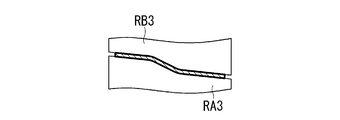
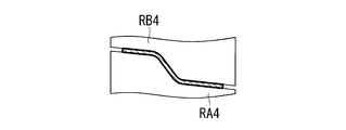
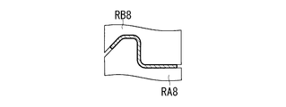
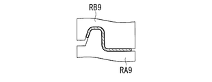
- the roll forming line is a forming line in which a plurality of forming rolls RA1 to RA13 having different cross-sectional shapes and RB1 to RB13 are arranged on the line.
- the metal material M is formed in stages as it sequentially passes between the forming rolls RA1 to RA13 and RB1 to RB13.
- a pinch point of a material to be formed by upper and lower rolls is set at a boundary between a target forming region in a material width direction and a pre-formed region or an un-formed region, and the target forming region Is formed along the predetermined caliber of the upper roll on the inner side of the bend, and in particular, the lower roll is hardly brought into contact with the outer side of the target forming region.
- the bending formability is remarkably improved, the occurrence of roll wrinkles, roll marks and buckling is prevented, the forming function in the breakdown forming part is enhanced, and the overall formability of the base plate is improved. It can be greatly improved.
- a recent aircraft stringer member is formed into a shape called a taper stringer as shown in FIG. 2B by using a taper material M ′ whose thickness repeatedly changes in a taper shape along the longitudinal direction. It has come to be molded.
- a taper stringer TS is designed to reduce the weight by keeping the plate thickness Tmax of the portion to be coupled with other members of the machine body large and minimizing the plate thickness Tmin of the other portions.
- the portion of the plate thickness Tmax and the portion of the plate thickness Tmin are similarly set to 90 °.
- the bending angle of the portion having the plate thickness Tmax is 90 °
- the bending angle of the portion having the plate thickness Tmin is larger than 90 °. The reason is that the plate thickness Tmin has a smaller volume in which permanent distortion is accumulated than the plate thickness Tmax, so that springback is likely to occur.
- the present invention has been made in view of such circumstances, and a metal material that can accurately roll-form a taper material whose thickness changes along the longitudinal direction with a simple and inexpensive configuration.
- An object is to provide a roll forming method and a roll forming apparatus.
- the metal material roll forming method according to the present invention is a plate-shaped metal material roll forming method in which the plate thickness varies along the longitudinal direction, and the metal material is placed between a plurality of forming roll sets. Feeding, having a multi-stage roll forming process in which the cross-sectional shape perpendicular to the longitudinal direction has a predetermined shape having a curved corner, and the final of the multi-stage roll forming processes In the one or a plurality of successive roll forming steps including a step, the corner portion is formed by a forming roll set having a corner radius of curvature smaller than a target radius of curvature at the corner portion of the metal material. .
- the corner radius of curvature is smaller than the target radius of curvature at the corner of the metal material.
- the corner portion is formed by a forming roll set having
- the bending angle of the metal material in the finishing process including the final stage is substantially equal to the target bending angle.
- the spring back is small in the portion where the metal material has a large plate thickness. , It is formed at an angle approximately equal to the target angle.
- the springback is large in the thin part, the bending angle after molding becomes larger than the target angle.
- the corner portion is formed by the forming roll set having a corner radius of curvature smaller than the target radius of curvature, a springback within an assumed range is generated in a thin portion of the plate thickness, and bending after forming is performed.
- the angle can be close to the target.
- the roll radius can be accurately formed by approximating the radius of curvature at the corner to the target radius of curvature.
- the roll forming step of forming with the forming roll set having the corner portion radius of curvature smaller than the target radius of curvature is performed a plurality of times, and at this time, from the front side to the back side
- the radius of curvature of the corner of the forming roll set is preferably decreased toward the front.
- the corner portion of the metal material is elastically deformed stepwise by a plurality of forming roll sets to a corner radius of curvature smaller than the target radius of curvature. For this reason, it can suppress more effectively that a springback arises in a corner part.
- the roll forming apparatus is a roll forming apparatus that feeds a plate-shaped metal material between a plurality of stages of forming roll sets, and forms the cross-sectional shape of the metal material into a predetermined shape step by step.
- one or a plurality of continuous forming roll sets including the final forming roll set have corner portions curved in a cross section perpendicular to the longitudinal direction of the metal material.
- a convex forming part to be molded, and a concave forming part facing the convex forming part, and the corner radius of curvature of the convex forming part is for the springback after molding, It is set smaller than the target radius of curvature at the corner portion of the metal material.
- a plurality of the forming roll sets having the convex forming portion having the corner radius of curvature smaller than the target radius of curvature are provided, and the corner radius of curvature is changed from the front side to the rear side. It is preferable to make it small toward the side.
- the corner portion of the metal material is elastically deformed step by step to a corner radius of curvature smaller than the target radius of curvature by a plurality of forming roll groups. For this reason, it can suppress more effectively that a springback arises in a corner part.
- one of the forming rolls that abuts on one surface of the metal material is provided concentrically with respect to one of the roll shafts, and abuts against the other surface of the metal material and the one of the forming rolls
- the other forming roll opposite to the other roll shaft is provided so as to be eccentric with respect to the other roll shaft, and the other forming roll provided to be eccentric is provided by a pressing roll that comes into contact with the outer peripheral portion thereof. You may make it press on the one said forming roll side provided concentrically.
- the metal material is a taper material whose plate thickness repeatedly changes along the longitudinal direction
- the metal material is formed while being pressed with a constant force without impairing the plate thickness of the metal material. can do.
- the taper stringer of an aircraft etc. can be shape
- the metal material may be a tapered material whose plate thickness repeatedly changes in the longitudinal direction.
- a part whose cross section changes such as an aircraft taper stringer.
- the roll forming apparatus As described above, according to the roll forming apparatus according to the present invention, it is possible to roll-form a taper material whose thickness changes in the longitudinal direction with high accuracy with a simple and inexpensive configuration.
- FIG. 3 is a longitudinal sectional view of the roll forming apparatus according to the embodiment of the present invention.
- the roll forming apparatus 1 easily forms a taper material M ′ (metal material) whose plate thickness repeatedly changes in a taper shape along the longitudinal direction shown in FIG. 2A into a taper stringer TS shown in FIG. 2B. be able to.
- the roll forming apparatus 1 according to the present embodiment includes a finishing process including a final stage (FIG. 1M) among roll forming lines shown in FIGS. 1A to 1M in which a plurality of forming rolls having different cross-sectional shapes are arranged on the line.
- the first stage molding (FIG. 1J) of (FIGS. 1J to 1M) is performed.
- the roll forming apparatus 1 includes two upper and lower horizontal roll shafts 7A and 7B.
- the two roll shafts 7A and 7B are engaged with each other by gears 8A and 8B fixed to the ends thereof.
- a rotational driving force R is applied from a driving source such as an electric motor (not shown) provided on one roll shaft 7A
- the two roll shafts 7A and 7B are interlocked with each other at a constant speed in opposite rotation directions.
- Rotate That is, the roll shaft 7A is a drive shaft and the roll shaft 7B is a driven shaft.
- the roll shaft 7A and the roll shaft 7B are respectively provided with fixed rolls 11A and 11B (one forming roll) concentrically. These fixed rolls 11A and 11B rotate integrally with the roll shafts 7A and 7B, respectively.
- the upper fixed roll 11B is a stepped roll.
- the roll shaft 7A and the roll shaft 7B are provided with floating rolls 12A and 12B (the other forming roll) so as to be eccentric. These floating rolls 12A and 12B are rotatable relative to the roll shafts 7A and 7B, respectively.
- the floating roll 12A can move a little in the axial direction of the roll shaft 7A. The amount of movement is approximately the same as the maximum thickness Tmax of the taper material M ′, but may be larger.
- the roll shaft 7A is provided with a fixed roll 11A and a floating roll 12A adjacent in the axial direction
- the roll shaft 7B is provided with a fixed roll 11B and a floating roll 12B adjacent in the axial direction.
- the fixed roll 11A provided on the roll shaft 7A faces the floating roll 12B provided on the roll shaft 7B
- the fixed roll 11B provided on the roll shaft 7B faces the floating roll 12A provided on the roll shaft 7A. is doing.
- the fixed roll 11A and the floating roll 12A provided on the roll shaft 7A constitute a combination roll RA10 that abuts one surface of the taper material M ′, and the fixed roll provided on the roll shaft 7B.
- the roll 11B and the floating roll 12B constitute a combination roll RB10 that comes into contact with the other surface of the tapered material M ′.
- the combination rolls RA10 and RB10 form a pair of forming rolls, and the taper material M 'is sent between the forming rolls RA10 and RB10 and roll-formed.
- the taper material M ′ (taper stringer TS) is sent and molded between the fixed roll 11A and the floating roll 12B and between the floating roll 12A and the fixed roll 11B.
- the cross-sectional shape of the taper material M ′ is a shape bent in a crank shape (channel shape), between the side surface of the floating roll 12A and the side surface of the floating roll 12B, and between the side surface of the floating roll 12A and the side surface of the fixed roll 11B.
- a taper material M ′ is also sandwiched between them.
- clearances CA and CB are provided between the roll shaft 7A and the floating roll 12A, and between the roll shaft 7B and the floating roll 12B, respectively.
- the floating rolls 12A and 12B can be eccentric with respect to the fixed rolls 11A and 11B by the clearances CA and CB.
- the sizes of the clearances CA and CB need to be larger than the difference between the maximum plate thickness and the minimum plate thickness of the taper material M ′. For example, when the maximum plate thickness of the taper material M ′ is 3 mm and the minimum plate thickness is 1 mm, the clearances CA and CB are set larger than the plate thickness difference of 2 mm.
- one surface of the adjacent portion of the fixed rolls 11 ⁇ / b> A and 11 ⁇ / b> B and the adjacent floating rolls 12 ⁇ / b> A and 12 ⁇ / b> B has a circumferential direction.
- a plurality of (for example, eight) driving recesses 15 are formed. Further, the same number of loosely fitted drive driving recesses 15 of the fixed rolls 11A and 11B is provided on the other surface of the adjacent portions of the fixed rolls 11A and 11B and the floating rolls 12A and 12B, for example, the side surfaces of the floating rolls 12A and 12B.
- a driving convex portion 16 is formed.
- Eccentric margins EA and EB are provided between the driving concave portion 15 and the driving convex portion 16 so that the floating rolls 12A and 12B can be eccentric.
- the sizes of the eccentric margins EA and EB are set to be approximately the same as the sizes of the clearances CA and CB between the roll shafts 7A and 7B and the floating rolls 12A and 12B.
- the driving concave portion 15 is formed on the fixed rolls 11A and 11B side and the driving convex portion 16 is formed on the floating rolls 12A and 12B side.
- the driving concave portion 15 is driven on the fixed rolls 11A and 11B side.
- the convex portion 16 for driving may be formed, and the concave portion 15 for driving may be formed on the floating rolls 12A and 12B side.
- a pressing roll 19 is in contact with each of the floating rolls 12A and 12B. These pressing rolls 19 are pivotally supported by roll carriers 21A and 21B, respectively. And actuator 23A, 23B which presses floating roll 12A, 12B to fixed roll 11A, 11B side via roll carrier 21A, 21B and the press roll 19 is provided. As these actuators 23A and 23B, for example, a hydraulic cylinder, an air cylinder or the like is used.
- the actuators 23A and 23B press the floating rolls 12A and 12B to the opposing fixed rolls 11A and 11B with the pressing force F through the roll carriers 21A and 21B and the pressing roll 19, respectively.
- the pressing force F is set to a constant force that changes only the cross-sectional shape without impairing the thickness of the taper material M ′.
- the combination rolls RA10 and RB10 are each bent with a corner portion CR that bends the taper material M ′ at a right angle in a cross-sectional view orthogonal to the longitudinal direction, for example. Mold into shape.
- three corner portions CR are formed in the cross section of the taper material M ′, but only the central corner portion CR will be described here.
- a convex forming part FA that abuts on the inside of the corner part CR is provided on the outer peripheral part of the floating roll 12A constituting the combination roll RA10.
- the corner portion of the convex forming portion FA is R-chamfered.
- the corner radius of curvature is assumed to be r2.
- a concave forming portion FB facing the convex forming portion FA is formed at the stepped portion of the mating surface of the fixed roll 11B and the floating roll 12B constituting the combination roll RB10.
- the sandwiching angle of the concave forming portion FB is a right angle, but may be an R shape as long as it is smaller than the corner radius of curvature r2 or the radius of curvature of the outer periphery of the corner CR.
- the corner portion radius of curvature r2 of the convex forming portion FA of the combination roll RA10 (floating roll 12A) in this forming roll set RA10, RB10 is the forming roll in the preceding roll forming step shown in FIG.
- the radius is set to be smaller than the corner radius of curvature r1 (indicated by a two-dot chain line in FIG. 5) of the set RA9, RB9.
- the corner radius of curvature r2 is set equal to the target radius of curvature rt at the corner CR of the taper material M ′.
- the corner angle of the forming roll set (any one of RA11 to 13 and RB11 to 13 shown in the roll forming step (FIGS. 1K to 1M) which is the subsequent stage of the forming roll set RA10 and RB10.
- the partial radius of curvature r3 is set to a value smaller than the corner radius of curvature r2.
- RB10 is only one stage of the forming roll group RA11, RB11, the forming roll group RA11, RB11 is the final stage, and the corner radius of curvature is r3.
- r1 is set to 5.00 mm
- r2 (rt) is set to 4.82 mm
- r3 is set to 4.32 mm.
- the radius of curvature at the corner CR is reduced to 4.32 mm, which is r3, when forming with the forming roll assembly having the corner radius of curvature r3.
- the outer peripheral line in the corner CR is expanded outward as indicated by the symbol ro.
- the roll forming apparatus 1 is configured as described above.
- a combination roll RA10 including a fixed roll 11A concentrically provided on the roll shaft 7A and a floating roll 12A provided eccentrically and a roll shaft 7B provided concentrically.
- the taper material M ′ is fed between the fixed roll 11B and the combination roll RB10 including the floating roll 12B provided to be eccentric.
- the actuators 23A and 23B press the floating rolls 12A and 12B to the opposing fixed rolls 11A and 11B via the pressing rolls 19, respectively.
- the cross-sectional shape of the taper material M ′ is finally formed according to the shapes of the fixed rolls 11A and 11B and the floating rolls 12A and 12B. That is, the corner portion CR in the cross section of the taper material M ′ is curved and formed into the corner portion curvature radius r2, that is, the target curvature radius rt by the convex forming portion FA of the floating roll 12A.
- one or a plurality of continuous roll forming steps including the final step (FIG. 1M) among the roll forming steps (FIGS. 1A to 1M).
- a forming roll assembly (any of RA11 to 13 and RB11 to 13) having a corner radius of curvature r3 smaller than the target radius of curvature rt (r2) at the corner CR of the tapered material M ′.
- the corner portion CR is formed.
- the bending angle of the taper material M ′ in the finishing process including the final stage is substantially equal to the target bending angle.
- the corner portion CR is formed by a forming roll set having a corner radius of curvature equal to the target radius of curvature rt at the corner portion CR of the taper material M ′
- the thickness of the taper material M ′ is thick. Since the spring back is small, the portion is formed at an angle substantially equal to the target angle. However, since the springback is large in the thin part, the bending angle after molding becomes larger than the target angle.
- the corner CR is formed by the forming roll groups RA11 to RA13 and RB11 to RB11 to 13 having the corner radius r3 smaller than the target radius rt. Spring back can be generated, and the bending angle after molding can be brought close to the target.
- the portion with a large plate thickness (the portion with the plate thickness Tmax shown in FIG. 2B) where the amount of generated springback is small and the shape is almost out is 90. Molded as it is.
- the thin portion where the springback is likely to occur (the portion having the plate thickness Tmin shown in FIG. 2B) is more effective in reducing the bending R than the thick portion. It can be closer. Specifically, it can be within a range of about ⁇ 3 ° with respect to a target forming angle of 90 °.
- the bending angle at the corner portion CR becomes the target angle due to the occurrence of a large amount of springback at the corner portion CR. It can suppress that it expands more than (90 degree
- the corner portion CR of the taper material M ′ is bent in a plurality of stages, the influence of the springback can be reduced and the curvature radius accuracy of the corner portion CR can be improved. Therefore, the taper material M ′ whose thickness changes in the longitudinal direction can be roll-formed accurately and stably with a simple and inexpensive configuration.
- the plate thickness of the taper material M ′ changes in a taper shape along the longitudinal direction, but the floating rolls 12A and 12B are eccentric with respect to the roll shafts 7A and 7B in accordance with the change in the plate thickness. Thus, the difference in plate thickness is absorbed.
- the pressing force F of the actuators 23A and 23B is applied to the floating rolls 12A and 12B themselves via the pressing roll 19, and is not applied to the roll shafts 7A and 7B on which the floating rolls 12A and 12B are provided.
- the taper material M ′ is predetermined while applying a constant pressing force F regardless of the eccentric position of the floating rolls 12A and 12B with respect to the roll shafts 7A and 7B, that is, regardless of the thickness of the taper material M ′. It can be formed into a shape.
- the pressing force F of the actuators 23A and 23B is set to a constant force that changes only the cross-sectional shape without impairing the thickness of the taper material M ′, so that the thickness of the taper material M ′ is reduced.
- the taper material M ′ is roll-formed into a predetermined cross-sectional shape while maintaining the originally planned plate thickness.
- the roll forming apparatus 1 As described above, according to the roll forming apparatus 1 according to the present embodiment, it is possible to roll-form the taper material M ′ whose thickness changes repeatedly in the longitudinal direction with high accuracy with a simple and inexpensive configuration.
- the floating rolls 12A and 12B are provided so as to be eccentric with respect to the roll shafts 7A and 7B, and these floating rolls 12A and 12B are connected to the actuators 23A and 23B via the pressing roll 19, respectively. It is the structure pressed by the fixed roll 11A, 11B side.
- the taper material M ′ whose plate thickness repeatedly changes along the longitudinal direction can be molded while being pressed with a constant force without impairing the plate thickness.
- the taper stringer TS etc. of an aircraft can be accurately shape
- FIG. 6 is a longitudinal sectional view showing a second embodiment of the present invention. This figure is the same as the configuration of FIG. 5 except that the corner radius of curvature r3, r4, r5 of the forming roll set that is the subsequent stage of the forming roll set RA10, RB10 is entered, so that each part is shown in FIG.
- the corner radius of curvature r2 of the combination roll RA10 (floating roll 12A) is set equal to the target radius of curvature rt in the corner CR of the tapered material M '. Then, the corner radius of curvature r3 of the forming roll group (RA11, RB11 to RA13, RB13) shown in the forming roll group (FIG. 1K, FIG. 1I, FIG. 1J) that is the subsequent stage of this forming roll group (RA10 / RB10). r4 and r5 are set smaller than the target curvature radius rt.
- r1 is set to 5.00 mm
- r2 (rt) is set to 4.82 mm
- r3 is set to 4.62 mm
- r4 is set to 4.52 mm
- r5 is set to 4.32 mm.
- the taper material M ′ after the taper material M ′ is roll-formed by the forming roll group (RA10 / RB10) having the target curvature radius rt (r2), the taper material M ′ has the target curvature radii r3, r4, r5 smaller than the target curvature radius rt.
- a plurality of rolls are formed by the roll sets (RA11, RB11 to RA13, RB13), and at this time, the corner radius of curvature r3, r4, r5 decreases from the front side to the rear side.
- the outer peripheral line of the corner CR is expanded outward as indicated by the symbol ro.
- the corner CR of the taper material M ′ is smaller than the target curvature radius rt by the plurality of forming roll groups (RA11 / RB11 to RA13 / RB13). Since the elastic deformation is performed step by step to the radii r3, r4, and r5, it is possible to more effectively suppress the occurrence of springback in the corner portion CR.
- the two roll shafts 7A and 7B are provided in a state in which the distance between the axes is fixed, but the distance between the axes may be variable.
- angular part CR of taper raw material M ' is 90 degrees, it is not specifically limited to 90 degrees, Other angles may be sufficient.
- the shape of the taper material M ′ and the shape of the taper stringer TS formed by the taper material M ′ are not limited to those of the above embodiment.
- the present invention is not limited to the forming roll assembly in the finishing process, but may be applied to, for example, an intermediate stage forming roll assembly that performs molding at the positions shown in FIGS. 1G to 1I.
- the corner radius of curvature in each forming roll set may be gradually reduced.
Landscapes
- Engineering & Computer Science (AREA)
- Mechanical Engineering (AREA)
- Bending Of Plates, Rods, And Pipes (AREA)
Abstract
長手方向に沿って板厚が変化する板状の金属材料(M')のロール成形方法であって、金属材料(M')を、複数の成形ロール組(RA1~RA13,RB1~RB13)の間に送り、その長手方向に直交する断面形状が湾曲した隅角部(CR)を有する所定形状となるように段階的に成形する複数段のロール成形工程を有し、このうち、最終段を含む1または複数段の連続する前記ロール成形工程においては、金属材料(M')の隅角部(CR)における目標曲率半径(rt)よりも小さな隅角部曲率半径(r3~r5)を有する成形ロール組(RA11~RA13,RB11~RB13)によって隅角部(CR)を成形することを特徴とする。
Description
本発明は、複数段の成形ロールの間に板状の金属材料を送り、この金属材料の断面形状を段階的に所定の形状に成形する金属材料のロール成形方法およびロール成形装置に関するものである。
例えば、図1Aに示す平坦な帯板状の金属材料Mを、図1Mに示す屈曲した断面形状を持つ航空機のストリンガー部材S等に成形する場合には、図1B~図1Lに示す複数のロール成形工程を経て段階的に成形が行われる。
これら複数のロール成形工程は、特許文献1に開示されているような、ロールフォーミングラインと呼ばれるロール成形装置によって行われる。ロールフォーミングラインは、図1A~図1Mに示すように、断面形状の異なる複数段の成形ロールRA1~RA13と、RB1~RB13とをライン上に配列させた成形ラインである。金属材料Mは、成形ロールRA1~RA13と、RB1~RB13との間を順次通過するにつれて段階的に成形されてゆく。
これら複数のロール成形工程は、特許文献1に開示されているような、ロールフォーミングラインと呼ばれるロール成形装置によって行われる。ロールフォーミングラインは、図1A~図1Mに示すように、断面形状の異なる複数段の成形ロールRA1~RA13と、RB1~RB13とをライン上に配列させた成形ラインである。金属材料Mは、成形ロールRA1~RA13と、RB1~RB13との間を順次通過するにつれて段階的に成形されてゆく。
特許文献1に開示されているロール成形方法は、上下ロールによる被成形素材のピンチポイントを素材幅方向の目標成形領域と既成形領域あるいは未成形領域との境目に設定して、当該目標成形領域を曲げ内側にある上ロールの所定カリバーに沿わせて、特に目標成形領域の曲げ外側には下ロールをほとんど当接させないようにして成形するようにしている。
このロール成形方法によれば、曲げ成形性を著しく向上させると共に、ロール疵、ロールマークや座屈の発生を防止し、ブレークダウン成形部での成形機能を高め、素板の全体の成形性を大きく向上させることができる。
近年の航空機用ストリンガー部材は、図2Bに示すように、長手方向に沿って板厚がテーパー状に大小繰り返し変化するテーパー素材M’を用いて、図2Bに示すようなテーパーストリンガーと呼ばれる形状に成形されるようになってきた。このようなテーパーストリンガーTSは、機体の他の部材と結合される部分の板厚Tmaxを大きく保ち、それ以外の部分の板厚Tminを最小限として軽量化を図ったものである。
上記のテーパー素材M’のように、長手方向に沿って板厚がテーパー状に変化する素材をロール成形する場合、例えば板厚Tmaxの部分と板厚Tminの部分とを同じように90°に曲げようとすると、板厚Tmaxの部分の曲げ角度は90°になっても、板厚Tminの部分の曲げ角度は90°よりも大きな角度になってしまう。その理由は、板厚Tminの方が板厚Tmaxよりも永久歪みが蓄積される体積が少ないことからスプリングバックが起こり易いためである。
したがって、このようなテーパー素材を精度良くロール成形することができなかった。特許文献1に記載されているロール成形方法によっても、この問題は解決し難い。
本発明は、このような事情に鑑みてなされたものであり、簡素で安価な構成により、長手方向に沿って板厚が大小に変化するテーパー素材を精度良くロール成形することのできる金属材料のロール成形方法およびロール成形装置を提供することを目的とする。
上記課題を解決するために、本発明は、以下の手段を採用する。
即ち、本発明に係る金属材料のロール成形方法は、長手方向に沿って板厚が変化する板状の金属材料のロール成形方法であって、前記金属材料を、複数の成形ロール組の間に送り、その長手方向に直交する断面形状が湾曲した隅角部を有する所定形状となるように段階的に成形する複数段のロール成形工程を有し、複数段の前記ロール成形工程のうち、最終段を含む1または複数段の連続する前記ロール成形工程においては、前記金属材料の前記隅角部における目標曲率半径よりも小さな隅角部曲率半径を有する成形ロール組によって前記隅角部を成形する。
上記構成の金属材料のロール成形方法によれば、最終段を含む1または複数段の連続する前記ロール成形工程においては、前記金属材料の隅角部における目標曲率半径よりも小さな隅角部曲率半径を有する成形ロール組によって隅角部が成形される。
ここで、最終段を含む仕上げ工程における前記金属材料の曲げ角度は、目標とする曲げ角度とほぼ等しくなっている。例えば、金属材料の隅角部における目標曲率半径と同等の隅角部曲率半径を有する成形ロール組によって隅角部を成形した場合には、金属材料の板厚が厚い部分はスプリングバックが小さいため、ほぼ目標角度に等しい角度に成形される。しかし、板厚の薄い部分はスプリングバックが大きいため、成形後の曲げ角度が目標角度よりも大きくなる。
本発明では、目標曲率半径よりも小さな隅角部曲率半径を有する成形ロール組によって隅角部が成形されるため、板厚の薄い部分に想定範囲内のスプリングバックを発生させ、成形後の曲げ角度を目標に近づけることができる。
したがって、長手方向に沿って板厚がテーパー状に変化するテーパー素材であっても、その板厚変化方向に依存したスプリングバックの発生に応じて成形性を変化させ、その板厚の薄い部分の隅角部における曲率半径を目標曲率半径に近似させて精度良くロール成形することができる。
しかも、金属材料の隅角部を複数段階に分けて曲げるので、スプリングバックの影響をより小さくし、隅角部の曲率半径精度を高めることができる。これらのため、簡素で安価な構成により、長手方向に板厚が変化するテーパー素材を精度良く安定的にロール成形することができる。
上記の金属材料のロール成形方法においては、前記目標曲率半径よりも小さな前記隅角部曲率半径を有する前記成形ロール組によって成形する前記ロール成形工程を複数回行い、この時に、前段側から後段側に向かって前記成形ロール組の前記隅角部曲率半径を小さくしていくのが好ましい。
上記構成の金属材料のロール成形方法によれば、金属材料の隅角部が、複数の成形ロール組によって目標曲率半径よりも小さな隅角部曲率半径に段階的に弾性変形させられる。このため、隅角部にスプリングバックが起きることを一層効果的に抑制することができる。
本発明に係るロール成形装置は、複数段の成形ロール組の間に板状の金属材料を送り、該金属材料の断面形状を段階的に所定の形状に成形していくロール成形装置であって、複数段の前記成形ロール組のうち、最終段の前記成形ロール組を含む1または複数段の連続する前記成形ロール組は、前記金属材料の長手方向に直交する断面に湾曲した隅角部を成形する凸形成形部と、この凸形成形部に対向する凹形成形部と、を有し、前記凸形成形部の隅角部曲率半径は、成形後のスプリングバック分を見込んで、前記金属材料の前記隅角部における目標曲率半径よりも小さく設定されている。
上記構成のロール成形装置によれば、最終段を含む1または複数段の連続する前記ロール成形工程においては、前記金属材料の隅角部における目標曲率半径よりも小さな隅角部曲率半径を有する成形ロール組によって隅角部が成形される。
このため、前述したロール成形方法の作用・効果と同様に、スプリングバックが発生し易い板厚の薄い金属材料においても、その隅角部に多大なスプリングバックが発生することによって隅角部における屈曲角度が目標角度よりも拡がってしまうことを抑制することができる。これにより、例えば長手方向に沿って板厚が変化するテーパー素材であっても、その板厚の薄い部分を精度良く屈曲断面形状にロール成形することができる。
上記のロール成形装置においては、前記目標曲率半径よりも小さい前記隅角部曲率半径の前記凸形成形部を有する前記成形ロール組を複数段設け、その前記隅角部曲率半径を前段側から後段側に向かって小さくするのが好ましい。
上記構成の金属材料のロール成形装置によれば、金属材料の隅角部が、複数の成形ロール組によって目標曲率半径よりも小さな隅角部曲率半径に段階的に弾性変形させられる。このため、隅角部にスプリングバックが起きることを一層効果的に抑制することができる。
上記構成において、前記金属材料の一方の面に当接する一方の前記成形ロールは、一方のロール軸に対し同心状に設けられ、前記金属材料の他方の面に当接して前記一方の前記成形ロールに対向する他方の前記成形ロールは、他方のロール軸に対しクリアランスを介して偏心可能に設けられ、偏心可能に設けられている他方の前記成形ロールは、その外周部に当接する押圧ロールにより、同心状に設けられている一方の前記成形ロール側に押し付けられるようにしてもよい。
上記構成によれば、例えば金属材料が、その長手方向に沿って板厚が大小に繰り返し変化するテーパー素材であっても、該金属材料の板厚を損なうことなく一定の力で押圧しながら成形することができる。これにより、航空機のテーパーストリンガー等を精度よく成形して製造することができる。
上記構成において、前記金属材料は、長手方向に沿って板厚が大小に繰り返し変化するテーパー素材であってもよい。これにより、航空機のテーパーストリンガー等のように断面が変化する部品を製造することができる。
以上のように、本発明に係るロール成形装置によれば、簡素で安価な構成により、長手方向に沿って板厚が大小に変化するテーパー素材を精度良くロール成形することができる。
以下に、本発明の実施形態について図面を参照しながら説明する。
[第1実施形態]
図3は、本発明の実施形態に係るロール成形装置の縦断面図である。このロール成形装置1は、例えば、図2Aに示す長手方向に沿って板厚がテーパー状に大小繰り返し変化するテーパー素材M’(金属材料)を、図2Bに示すテーパーストリンガーTSに無理なく成形することができる。本実施形態におけるロール成形装置1は、図1A~図1Mに示す、断面形状の異なる複数段の成形ロールをライン上に配列させたロールフォーミングラインのうち、最終段(図1M)を含む仕上げ工程(図1J~図1M)の初段の成形(図1J)を行うものである。
図3は、本発明の実施形態に係るロール成形装置の縦断面図である。このロール成形装置1は、例えば、図2Aに示す長手方向に沿って板厚がテーパー状に大小繰り返し変化するテーパー素材M’(金属材料)を、図2Bに示すテーパーストリンガーTSに無理なく成形することができる。本実施形態におけるロール成形装置1は、図1A~図1Mに示す、断面形状の異なる複数段の成形ロールをライン上に配列させたロールフォーミングラインのうち、最終段(図1M)を含む仕上げ工程(図1J~図1M)の初段の成形(図1J)を行うものである。
図3に示すように、このロール成形装置1は、上下2本の水平なロール軸7A,7Bを備えている。これら2本のロール軸7A,7Bは、その端部に固定されたギア8A,8Bが互いに噛み合っている。そして、例えば一方のロール軸7Aに設けられた図示しない電動モータ等の駆動源から回転駆動力Rが付与されることにより、2本のロール軸7A,7Bは互いに逆の回転方向に等速連動回転する。つまり、ロール軸7Aが駆動軸、ロール軸7Bが従動軸となっている。
ロール軸7Aとロール軸7Bには、それぞれ固定ロール11A,11B(一方の成形ロール)が同心状に設けられている。これらの固定ロール11A,11Bは、各々ロール軸7A,7Bと一体に回転する。例えば上側の固定ロール11Bは段付きロールである。
また、ロール軸7Aとロール軸7Bには、それぞれ浮動ロール12A,12B(他方の成形ロール)が偏心可能に設けられている。これらの浮動ロール12A,12Bは、各々ロール軸7A,7Bに対して相対回転可能である。
例えば浮動ロール12Aは、ロール軸7Aの軸方向に少し移動することができる。その移動量は、テーパー素材M’の最大厚さTmaxと同程度とされているが、より大きくてしもよい。
例えば浮動ロール12Aは、ロール軸7Aの軸方向に少し移動することができる。その移動量は、テーパー素材M’の最大厚さTmaxと同程度とされているが、より大きくてしもよい。
ロール軸7Aには固定ロール11Aと浮動ロール12Aとが軸方向に隣接して設けられ、ロール軸7Bには固定ロール11Bと浮動ロール12Bとが軸方向に隣接して設けられている。
そして、ロール軸7Aに設けられた固定ロール11Aがロール軸7Bに設けられた浮動ロール12Bに対向し、ロール軸7Bに設けられた固定ロール11Bがロール軸7Aに設けられた浮動ロール12Aに対向している。
そして、ロール軸7Aに設けられた固定ロール11Aがロール軸7Bに設けられた浮動ロール12Bに対向し、ロール軸7Bに設けられた固定ロール11Bがロール軸7Aに設けられた浮動ロール12Aに対向している。
即ち、本実施形態では、ロール軸7Aに設けられた固定ロール11Aと浮動ロール12Aとが、テーパー素材M’の一方の面に当接するコンビネーションロールRA10を構成し、ロール軸7Bに設けられた固定ロール11Bと浮動ロール12Bとが、テーパー素材M’の他方の面に当接するコンビネーションロールRB10を構成している。そして、これらのコンビネーションロールRA10とRB10とが一対の成形ロール組を形成し、この成形ロール組RA10,RB10の間にテーパー素材M’が送られてロール成形される。
図4にも拡大して示すように、固定ロール11Aと浮動ロール12Bとの間、および浮動ロール12Aと固定ロール11Bとの間にテーパー素材M’(テーパーストリンガーTS)が送られて成形される。テーパー素材M’の断面形状はクランク状(チャンネル状)に屈曲した形状であり、浮動ロール12Aの側面と浮動ロール12Bの側面との間、および浮動ロール12Aの側面と固定ロール11Bの側面との間にもテーパー素材M’が挟まれる。
図3、図4に示すように、ロール軸7Aと浮動ロール12Aとの間、およびロール軸7Bと浮動ロール12Bとの間には、それぞれクリアランスCA,CBが設けられている。このクリアランスCA,CBの分だけ浮動ロール12A,12Bは固定ロール11A,11Bに対して偏心することができる。このクリアランスCA,CBの大きさは、テーパー素材M’の最大板厚と最小板厚との差よりも大きくする必要がある。例えば、テーパー素材M’の最大板厚が3mm、最小板厚が1mmである場合には、その板厚差の2mmよりもクリアランスCA,CBを大きく設定する。
図3、図4に示すように、固定ロール11A,11Bと、これに隣接する浮動ロール12A,12Bとの隣接部における一方の面、例えば固定ロール11A,11Bの側面には、円周方向に並ぶ複数(例えば8つ)の駆動用凹部15が形成されている。
また、固定ロール11A,11Bと浮動ロール12A,12Bとの隣接部における他方の面、例えば浮動ロール12A,12Bの側面には、固定ロール11A,11Bの駆動用凹部15に遊嵌される同数の駆動用凸部16が形成されている。
また、固定ロール11A,11Bと浮動ロール12A,12Bとの隣接部における他方の面、例えば浮動ロール12A,12Bの側面には、固定ロール11A,11Bの駆動用凹部15に遊嵌される同数の駆動用凸部16が形成されている。
これら駆動用凹部15と駆動用凸部16との間には、浮動ロール12A,12Bを偏心可能にする偏心代EA,EBが設けられている。この偏心代EA,EBの大きさは、ロール軸7A,7Bと浮動ロール12A,12Bとの間のクリアランスCA,CBの大きさと同程度に設定される。
なお、本実施形態では固定ロール11A,11B側に駆動用凹部15が形成され、浮動ロール12A,12B側に駆動用凸部16が形成されているが、逆に固定ロール11A,11B側に駆動用凸部16を形成し、浮動ロール12A,12B側に駆動用凹部15を形成してもよい。
なお、本実施形態では固定ロール11A,11B側に駆動用凹部15が形成され、浮動ロール12A,12B側に駆動用凸部16が形成されているが、逆に固定ロール11A,11B側に駆動用凸部16を形成し、浮動ロール12A,12B側に駆動用凹部15を形成してもよい。
浮動ロール12A,12Bの各々には、それぞれ押圧ロール19が当接している。これらの押圧ロール19は、それぞれロールキャリア21A,21Bに軸支されている。そして、ロールキャリア21A,21Bと押圧ロール19とを介して浮動ロール12A,12Bを固定ロール11A,11B側に押圧するアクチュエータ23A,23Bが設けられている。これらのアクチュエータ23A,23Bとしては、例えば油圧シリンダやエアシリンダ等が用いられる。
アクチュエータ23A,23Bは、それぞれロールキャリア21A,21Bおよび押圧ロール19を介して、浮動ロール12A,12Bを、対向する固定ロール11A,11B側に押圧力Fで押圧する。その押圧力Fは、テーパー素材M’の板厚を損なうことなく、その断面形状のみを変化させる一定の力に設定されている。
図3、図4、図5に示すように、コンビネーションロールRA10とRB10は、それぞれ、テーパー素材M’を、その長手方向に直交する断面視で、例えば直角に屈曲する隅角部CRを有する屈曲形状に成形する。この隅角部CRは、例えばテーパー素材M’の断面に3箇所形成されているが、ここでは中央の隅角部CRについてのみ説明する。
図5に拡大して示すように、例えばコンビネーションロールRA10を構成する浮動ロール12Aの外周部には、隅角部CRの内側に当接する凸形成形部FAが設けられている。この凸形成形部FAの隅角部はR面取りがなされている。その隅角部曲率半径をr2と仮定する。
一方、コンビネーションロールRB10を構成する固定ロール11Bと浮動ロール12Bとの合面の段差部には、上記の凸形成形部FAに対向する凹形成形部FBが形成されている。この凹形成形部FBの挟み角は直角であるが、隅角部曲率半径r2や、隅角部CRの外周の湾曲半径よりも小さい半径であればR状であってもよい。
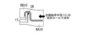
図5に示すように、この成形ロール組RA10,RB10におけるコンビネーションロールRA10(浮動ロール12A)の凸形成形部FAの隅角部曲率半径r2は、図1Iに示す前段のロール成形工程における成形ロール組RA9,RB9の隅角部曲率半径r1(図5中に二点鎖線で記入)よりも小さい半径に設定されている。さらに、この隅角部曲率半径r2は、テーパー素材M’の隅角部CRにおける目標曲率半径rtに等しく設定されている。
さらに、図5に示すように、この成形ロール組RA10,RB10の後段となる成形ロール組(ロール成形工程(図1K~図1M)に示すRA11~13,RB11~13のいずれか)の隅角部曲率半径r3は、隅角部曲率半径r2よりも小さい値に設定されている。成形ロール組RA10,RB10の後段を成形ロール組RA11,RB11の1段のみとする場合には、この成形ロール組RA11,RB11が最終段となり、その隅角部曲率半径がr3となる。具体的な数値としては、例えばr1が5.00mm、r2(rt)が4.82mm、r3が4.32mmに設定されている。
本構成によれば、図5中に二点鎖線で示すように、隅角部曲率半径r3を有する成形ロール組による成形時には隅角部CRにおける曲率半径がr3の4.32mmまで小さくなる。この時の隅角部CRにおける外周側のラインは符号roで示すように外側に膨らむ。
ロール成形装置1は以上のように構成されている。テーパー素材M’の成形を行う場合には、ロール軸7Aに同心状に設けられた固定ロール11Aおよび偏心可能に設けられた浮動ロール12AからなるコンビネーションロールRA10と、ロール軸7Bに同心状に設けられた固定ロール11Bおよび偏心可能に設けられた浮動ロール12BからなるコンビネーションロールRB10との間にテーパー素材M’が送り込まれる。
そして、アクチュエータ23A,23Bが、それぞれ押圧ロール19を介して浮動ロール12A,12Bを対向する固定ロール11A,11B側に押圧する。これにより、テーパー素材M’の断面形状が固定ロール11A,11Bと浮動ロール12A,12Bの形状に合わせて最終成形される。即ち、テーパー素材M’の断面にある隅角部CRが、浮動ロール12Aの凸形成形部FAによって隅角部曲率半径r2、即ち目標曲率半径rtに湾曲成形される。
このロール成形装置1およびロール成形方法によれば、ロール成形工程(図1A~図1M)のうち、最終段(図1M)を含む1または複数段の連続するロール成形工程(図1K、図1L、図1M)においては、テーパー素材M’の隅角部CRにおける目標曲率半径rt(r2)よりも小さな隅角部曲率半径r3を有する成形ロール組(RA11~13,RB11~13のいずれか)によって隅角部CRが成形される。
ここで、最終段(図1M)を含む仕上げ工程におけるテーパー素材M’の曲げ角度は、目標とする曲げ角度とほぼ等しくなっている。例えば、テーパー素材M’の隅角部CRにおける目標曲率半径rtと同等の隅角部曲率半径を有する成形ロール組によって隅角部CRを成形した場合には、テーパー素材M’の板厚が厚い部分はスプリングバックが小さいため、ほぼ目標角度に等しい角度に成形される。しかし、板厚の薄い部分はスプリングバックが大きいため、成形後の曲げ角度が目標角度よりも大きくなる。
本発明では、目標曲率半径rtよりも小さな隅角部曲率半径r3を有する成形ロール組RA11~13,RB11~13によって隅角部CRが成形されるため、板厚の薄い部分に想定範囲内のスプリングバックを発生させ、成形後の曲げ角度を目標に近づけることができる。
換言すると、通常、金属材料を屈曲・湾曲成形する場合のスプリングバックの対応としては、曲げ型の角度を目標角度よりも小さくしておき、スプリングバックが生じた時に目標形状に近似させるのが一般的である。
しかし、スプリングバックの角度は板厚に応じて変動するため、本実施形態におけるテーパー素材M’のように、長手方向に沿って板厚が大小に変化する金属材料では、スプリングバックの度合いは長手方向の場所毎に異なる。よって、上記のように曲げ角度を目標角度よりも小さくする手法では、板厚の厚い部分もしくは板厚の薄い部分のどちらかしか精度よく成形することはできない。
本実施形態のように、曲げRを小さくしてスプリングバックを見込む場合、スプリングバックの発生量が少なくほぼ形状が出ている板厚の厚い部分(図2Bに示す板厚Tmaxの部分)は90°のまま成形される。また、スプリングバックの発生し易い板厚の薄い部分(図2Bに示す板厚Tminの部分)は、曲げRを小さくする効果が板厚の厚い部分よりも多く付与されるため、曲げ角度を90°により近づけることができる。具体的には、目標の成形角度90°に対して±3°程度の範囲内に収めることができる。
このため、スプリングバックが発生し易い、板厚の薄い部分を備えたテーパー素材M’においても、その隅角部CRに多大なスプリングバックが発生することによって隅角部CRにおける曲げ角度が目標角度(90度)よりも拡がってしまうことを抑制することができる。
しかも、テーパー素材M’の隅角部CRを複数段階に分けて曲げるので、スプリングバックの影響をより小さくし、隅角部CRの曲率半径精度を高めることができる。したがって、簡素で安価な構成により、長手方向に板厚が変化するテーパー素材M’を精度良く安定的にロール成形することができる。
なお、テーパー素材M’の板厚は、長手方向に沿ってテーパー状に変化しているが、この板厚の変化に応じて浮動ロール12A,12Bがロール軸7A,7Bに対して偏心することにより、その板厚差が吸収される。
その際、アクチュエータ23A,23Bの押圧力Fは、押圧ロール19を介して浮動ロール12A,12B自身に付与され、浮動ロール12A,12Bが設けられているロール軸7A,7Bには付与されない。このため、ロール軸7A,7Bに対する浮動ロール12A,12Bの偏心位置に拘わらず、即ちテーパー素材M’の板厚の大小に拘わらず、一定の押圧力Fを付与しながらテーパー素材M’を所定の形状に成形することができる。
したがって、非常に簡素で安価な構成により、長手方向に板厚が大小繰り返し変化するテーパー素材M’を安定的にロール成形することができる。
アクチュエータ23A,23Bの押圧力Fは、テーパー素材M’の板厚を損なうことなく、その断面形状のみを変化させる一定の力に設定されているので、テーパー素材M’の板厚が薄くなることがなく、当初予定された板厚のままでテーパー素材M’が所定の断面形状にロール成形される。
以上のように、本実施形態に係るロール成形装置1によれば、簡素で安価な構成により、長手方向に板厚が大小繰り返し変化するテーパー素材M’を精度良くロール成形することができる。
さらに、このロール成形装置1は、浮動ロール12A,12Bがロール軸7A,7Bに対して偏心可能に設けられており、これらの浮動ロール12A,12Bが、押圧ロール19を介してアクチュエータ23A,23Bにより固定ロール11A,11B側に押圧される構成である。
このため、長手方向に沿って板厚が大小に繰り返し変化するテーパー素材M’を、その板厚を損なうことなく一定の力で押圧しながら成形することができる。これにより、航空機のテーパーストリンガーTS等を精度よく成形して製造することができる。
[第2実施形態]
図6は、本発明の第2実施形態を示す縦断面図である。この図においては、成形ロール組RA10,RB10の後段となる成形ロール組の隅角部曲率半径r3,r4,r5が記入されている点以外は図5の構成と同一であるため、各部に図5と同じ符号を付して説明を省略する。
図6は、本発明の第2実施形態を示す縦断面図である。この図においては、成形ロール組RA10,RB10の後段となる成形ロール組の隅角部曲率半径r3,r4,r5が記入されている点以外は図5の構成と同一であるため、各部に図5と同じ符号を付して説明を省略する。
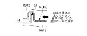
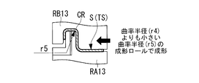
コンビネーションロールRA10(浮動ロール12A)の隅角部曲率半径r2は、テーパー素材M’の隅角部CRにおける目標曲率半径rtに等しく設定されている。そして、この成形ロール組(RA10/RB10)の後段となる成形ロール組(図1K、図1I、図1J)に示す成形ロール組(RA11,RB11~RA13,RB13)の隅角部曲率半径r3,r4,r5は、目標曲率半径rtよりも小さく設定されている。具体的な数値としては、例えばr1が5.00mm、r2(rt)が4.82mm、r3が4.62mm、r4が4.52mm,r5が4.32mmに設定されている。
即ち、テーパー素材M’は、目標曲率半径rt(r2)の成形ロール組(RA10/RB10)によってロール成形された後で、目標曲率半径rtよりも小さな目標曲率半径r3,r4,r5を有する成形ロール組(RA11,RB11~RA13,RB13)によって複数回ロール成形され、この時に、前段側から後段側に向かって隅角部曲率半径r3,r4,r5が小さくなってゆく。隅角部曲率半径r5を有する最終段の成形ロール組RA13,RB13による成形時には、隅角部CRにおける外周側のラインが符号roで示すように外側に膨らむ。
このロール成形装置1およびロール成形方法によれば、テーパー素材M’の隅角部CRが、複数の成形ロール組(RA11/RB11~RA13/RB13)によって目標曲率半径rtよりも小さな隅角部曲率半径r3,r4,r5に段階的に弾性変形させられるため、隅角部CRにスプリングバックが起きることを一層効果的に抑制することができる。
なお、本発明は上記各実施形態の構成のみに限定されるものではなく、本発明の要旨を逸脱しない範囲内において適宜変更や改良を加えることができ、このように変更や改良を加えた実施形態も本発明の権利範囲に含まれるものとする。
例えば、上記実施形態では、2本のロール軸7A,7Bが、その軸間距離を固定された状態で設けられているが、軸間距離を可変にすることもできる。
また、上記実施形態では、テーパー素材M’の隅角部CRの角度が90°となっているが、特に90°には限定されず、他の角度であってもよい。
また、上記実施形態では、テーパー素材M’の隅角部CRの角度が90°となっているが、特に90°には限定されず、他の角度であってもよい。
さらに、テーパー素材M’の形状や、このテーパー素材M’によって成形されるテーパーストリンガーTSの形状は、上記実施形態のものに限定されない。
さらにまた、本発明は仕上げ工程の成形ロール組は、図1Jから図1Mのみに限定されず、例えば図1Gから図1Iの位置にて成形を行う中間段の成形ロール組に適用してもよく、各成形ロール組における隅角部曲率半径を徐々に小さくしてもよい。
さらにまた、本発明は仕上げ工程の成形ロール組は、図1Jから図1Mのみに限定されず、例えば図1Gから図1Iの位置にて成形を行う中間段の成形ロール組に適用してもよく、各成形ロール組における隅角部曲率半径を徐々に小さくしてもよい。
1 ロール成形装置
7A,7B ロール軸
11A,11B 一方の成形ロール
12A,12B 他方の成形ロール
19 押圧ロール
23A,23B アクチュエータ
CA,CB クリアランス
CR 隅角部
FA 凸形成形部
FB 凹形成形部
M’ テーパー素材(金属材料)
RA1~RA13/RB1~RB13 成形ロール組
r1 中間段の成形ロール組における凸形成形部の隅角部曲率半径
r2,r3 後段の成形ロール組における凸形成形部の隅角部曲率半径
rt テーパー素材(金属材料)の隅角部における目標曲率半径
7A,7B ロール軸
11A,11B 一方の成形ロール
12A,12B 他方の成形ロール
19 押圧ロール
23A,23B アクチュエータ
CA,CB クリアランス
CR 隅角部
FA 凸形成形部
FB 凹形成形部
M’ テーパー素材(金属材料)
RA1~RA13/RB1~RB13 成形ロール組
r1 中間段の成形ロール組における凸形成形部の隅角部曲率半径
r2,r3 後段の成形ロール組における凸形成形部の隅角部曲率半径
rt テーパー素材(金属材料)の隅角部における目標曲率半径
Claims (6)
- 長手方向に沿って板厚が変化する板状の金属材料のロール成形方法であって、
前記金属材料を、複数の成形ロール組の間に送り、その長手方向に直交する断面形状が湾曲した隅角部を有する所定形状となるように段階的に成形する複数段のロール成形工程を有し、
複数段の前記ロール成形工程のうち、最終段を含む1または複数段の連続する前記ロール成形工程においては、前記金属材料の前記隅角部における目標曲率半径よりも小さな隅角部曲率半径を有する成形ロール組によって前記隅角部を成形する金属材料のロール成形方法。 - 前記目標曲率半径よりも小さな前記隅角部曲率半径を有する前記成形ロール組によって成形する前記ロール成形工程を複数回行い、この時に、前段側から後段側に向かって前記成形ロール組の前記隅角部曲率半径を小さくしていく請求項1に記載の金属材料のロール成形方法。
- 複数段の成形ロール組の間に板状の金属材料を送り、該金属材料の断面形状を段階的に所定の形状に成形していくロール成形装置であって、
複数段の前記成形ロール組のうち、最終段の前記成形ロール組を含む1または複数段の連続する前記成形ロール組は、前記金属材料の長手方向に直交する断面に湾曲した隅角部を成形する凸形成形部と、この凸形成形部に対向する凹形成形部と、を有し、
前記凸形成形部の隅角部曲率半径は、前記金属材料の前記隅角部における目標曲率半径よりも小さく設定されているロール成形装置。 - 前記目標曲率半径よりも小さい前記隅角部曲率半径の前記凸形成形部を有する前記成形ロール組は複数段あり、その前記隅角部曲率半径は前段側から後段側に向かって小さくなる請求項3に記載のロール成形装置。
- 前記金属材料の一方の面に当接する一方の前記成形ロールは、一方のロール軸に対し同心状に設けられ、
前記金属材料の他方の面に当接して前記一方の前記成形ロールに対向する他方の前記成形ロールは、他方のロール軸に対しクリアランスを介して偏心可能に設けられ、
偏心可能に設けられている他方の前記成形ロールは、その外周部に当接する押圧ロールにより、同心状に設けられている一方の前記成形ロール側に押し付けられる請求項3または4に記載のロール成形装置。 - 前記金属材料は、長手方向に沿って板厚が大小に繰り返し変化するテーパー素材である請求項3から5のいずれかに記載のロール成形装置。
Applications Claiming Priority (2)
| Application Number | Priority Date | Filing Date | Title |
|---|---|---|---|
| JP2015-164709 | 2015-08-24 | ||
| JP2015164709A JP2017042771A (ja) | 2015-08-24 | 2015-08-24 | 金属材料のロール成形方法およびロール成形装置 |
Publications (1)
| Publication Number | Publication Date |
|---|---|
| WO2017033656A1 true WO2017033656A1 (ja) | 2017-03-02 |
Family
ID=58100036
Family Applications (1)
| Application Number | Title | Priority Date | Filing Date |
|---|---|---|---|
| PCT/JP2016/072092 Ceased WO2017033656A1 (ja) | 2015-08-24 | 2016-07-27 | 金属材料のロール成形方法およびロール成形装置 |
Country Status (2)
| Country | Link |
|---|---|
| JP (1) | JP2017042771A (ja) |
| WO (1) | WO2017033656A1 (ja) |
Citations (5)
| Publication number | Priority date | Publication date | Assignee | Title |
|---|---|---|---|---|
| JPS56500682A (ja) * | 1979-06-18 | 1981-05-21 | ||
| JPH02160134A (ja) * | 1988-12-13 | 1990-06-20 | Mitsubishi Heavy Ind Ltd | Al−Li合金形材の製作方法 |
| JPH0999323A (ja) * | 1995-10-02 | 1997-04-15 | Mitsubishi Heavy Ind Ltd | 帯板曲折加工ロール装置 |
| JP2000263141A (ja) * | 1999-03-19 | 2000-09-26 | Sanko Metal Ind Co Ltd | 建築用板の成形方法 |
| JP2012006083A (ja) * | 2011-08-24 | 2012-01-12 | Nakata Mfg Co Ltd | ロール成形方法 |
-
2015
- 2015-08-24 JP JP2015164709A patent/JP2017042771A/ja active Pending
-
2016
- 2016-07-27 WO PCT/JP2016/072092 patent/WO2017033656A1/ja not_active Ceased
Patent Citations (5)
| Publication number | Priority date | Publication date | Assignee | Title |
|---|---|---|---|---|
| JPS56500682A (ja) * | 1979-06-18 | 1981-05-21 | ||
| JPH02160134A (ja) * | 1988-12-13 | 1990-06-20 | Mitsubishi Heavy Ind Ltd | Al−Li合金形材の製作方法 |
| JPH0999323A (ja) * | 1995-10-02 | 1997-04-15 | Mitsubishi Heavy Ind Ltd | 帯板曲折加工ロール装置 |
| JP2000263141A (ja) * | 1999-03-19 | 2000-09-26 | Sanko Metal Ind Co Ltd | 建築用板の成形方法 |
| JP2012006083A (ja) * | 2011-08-24 | 2012-01-12 | Nakata Mfg Co Ltd | ロール成形方法 |
Also Published As
| Publication number | Publication date |
|---|---|
| JP2017042771A (ja) | 2017-03-02 |
Similar Documents
| Publication | Publication Date | Title |
|---|---|---|
| US10406579B2 (en) | Apparatus and method for ram bending of tube material | |
| TWI683707B (zh) | 變厚度式金屬板的製造方法、壓製部件的製造方法及加工機 | |
| CN105592946B (zh) | 截面形状在长度方向上变化的型钢的制造方法和辊轧成形装置 | |
| CN105478542B (zh) | 辊轧成形辊以及使用该辊轧成形辊的辊轧成形方法 | |
| JP5680086B2 (ja) | 球面ころ軸受 | |
| JP2002364651A (ja) | ころがり軸受保持器 | |
| CN111867747A (zh) | 冲压成型用的金属板、冲压成型装置和冲压部件的制造方法 | |
| US10612653B2 (en) | Metal element for continuously variable transmission and method of manufacturing metal element for continuously variable transmission | |
| CN107626781B (zh) | 一种可调四辊卷板机 | |
| JP4320599B2 (ja) | ラジアルニードル軸受用保持器の製造方法 | |
| EP2583765B1 (en) | Method for manufacturing a pedal for a motor vehicle, and pedal obtained according to the manufacturing method | |
| JP2017042771A (ja) | 金属材料のロール成形方法およびロール成形装置 | |
| JP6342365B2 (ja) | ロール成形装置 | |
| WO2016175179A1 (ja) | 圧延加工装置、湾曲加工方法、湾曲加工材料 | |
| JP4923597B2 (ja) | 円筒状軸製品の成形方法および成形金型 | |
| EP3395466B1 (en) | Roll stamping apparatus | |
| KR102412105B1 (ko) | 롤 스탬핑 장치 | |
| JP4924653B2 (ja) | 円筒軸の製造方法 | |
| KR102921829B1 (ko) | 롤 포밍 장치용 성형롤 | |
| US12409488B2 (en) | Method for manufacturing bearing ring member | |
| JP7760868B2 (ja) | 軸受用シェル部材の製造方法及び軸受の製造方法 | |
| JP7775599B2 (ja) | 軸受用シェル部材の製造方法及び軸受の製造方法 | |
| JP2023112992A (ja) | 軸受用リング部材の製造方法 | |
| WO2015127509A1 (en) | Method and apparatus for forming profiled articles | |
| JP2010005653A (ja) | パイプ曲げ装置 |
Legal Events
| Date | Code | Title | Description |
|---|---|---|---|
| 121 | Ep: the epo has been informed by wipo that ep was designated in this application |
Ref document number: 16839003 Country of ref document: EP Kind code of ref document: A1 |
|
| NENP | Non-entry into the national phase |
Ref country code: DE |
|
| 122 | Ep: pct application non-entry in european phase |
Ref document number: 16839003 Country of ref document: EP Kind code of ref document: A1 |