WO2017033655A1 - ブラシ装置付き電動機 - Google Patents
ブラシ装置付き電動機 Download PDFInfo
- Publication number
- WO2017033655A1 WO2017033655A1 PCT/JP2016/071952 JP2016071952W WO2017033655A1 WO 2017033655 A1 WO2017033655 A1 WO 2017033655A1 JP 2016071952 W JP2016071952 W JP 2016071952W WO 2017033655 A1 WO2017033655 A1 WO 2017033655A1
- Authority
- WO
- WIPO (PCT)
- Prior art keywords
- brush
- positive
- electrode side
- negative
- subassembly
- Prior art date
- Legal status (The legal status is an assumption and is not a legal conclusion. Google has not performed a legal analysis and makes no representation as to the accuracy of the status listed.)
- Ceased
Links
Images

Classifications
-
- H—ELECTRICITY
- H02—GENERATION; CONVERSION OR DISTRIBUTION OF ELECTRIC POWER
- H02K—DYNAMO-ELECTRIC MACHINES
- H02K5/00—Casings; Enclosures; Supports
- H02K5/04—Casings or enclosures characterised by the shape, form or construction thereof
- H02K5/14—Means for supporting or protecting brushes or brush holders
-
- H—ELECTRICITY
- H02—GENERATION; CONVERSION OR DISTRIBUTION OF ELECTRIC POWER
- H02K—DYNAMO-ELECTRIC MACHINES
- H02K13/00—Structural associations of current collectors with motors or generators, e.g. brush mounting plates or connections to windings; Disposition of current collectors in motors or generators; Arrangements for improving commutation
Definitions
- the present invention relates to a brush device for an electric motor.
- a brush or the like is assembled after two annular printed circuit boards and two guide plates made of an insulating material are coupled.
- the annular printed circuit board and the guide plate are fixed, the assembly space for the brush and the like is narrow, and the assembly work is difficult.
- the brush device includes a positive electrode brush that supplies power to the commutator, a positive electrode brush holder that holds the positive electrode brush, a positive electrode side brush subassembly having a positive electrode side plate to which the positive electrode brush holder is attached, a negative electrode brush that supplies power to the commutator, and a negative electrode brush And a negative electrode brush subassembly having a negative electrode plate to which the negative electrode brush holder is attached.
- the positive electrode brush subassembly and the negative electrode brush subassembly are fixed or positioned with respect to each other.
- the assembly workability of the brush device is improved.
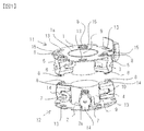
- FIG. 1 is an overall view of a brush apparatus showing an example of the apparatus of the present invention, and shows a state before a positive electrode side brush subassembly 11 and a negative electrode side brush subassembly 12 described later are coupled.
- the brush device according to the present embodiment is a device for supplying power to a commutator of an electric motor (not shown), and includes a positive electrode side brush subassembly 11 and a negative electrode side brush subassembly 12.
- the positive electrode side brush subassembly 11 and the negative electrode side brush subassembly 12 are each comprised independently.
- the positive electrode side brush subassembly 11 is accommodated in the positive electrode side plate 1, three brush holders 5 fixed to the positive electrode side plate 1, a brush spring (not shown) accommodated in the brush holder 5, and the brush holder 5.
- the positive plate 1 is a disk-like member connected to the plus side of the power source, and has a through hole 1a through which a commutator (not shown) of the electric motor passes.
- the brush holder 5 is a resin brush holder that holds the positive brush 3 that supplies power to a commutator (not shown).
- the three brush holders 5 are respectively attached to the lower surface of the positive plate 1 in FIG. 1 around the through hole 1a at intervals of about 120 degrees around the through hole 1a. That is, the positive electrode side plate 1 holds the positive electrode brush 3 via the brush holder 5.
- the positive electrode brush 3 is held by a brush holder 5 and is urged by a ring 9 which is an assembly jig by an urging force of a brush spring provided in the brush holder 5.
- the ring 9 is a cylinder having a slightly smaller diameter than the through hole 1a.
- the positive electrode brush 3 and the positive electrode side plate 1 are connected by a positive electrode side brush lead wire 6.
- the fixing plate 15 for fixing the brush holder 5 is provided in the positive electrode side plate 1.
- the fixing holes 15 are provided at three locations at intervals of about 120 degrees around the through hole 1a.
- the fixing hole 15 is engaged with a hook of a hook portion 8 (described later) provided on the upper surface of the brush holder 5.
- the positive plate 1 is provided with holes 13 between the adjacent fixing holes 15.
- the holes 13 are attached to three places at intervals of about 120 degrees around the through hole 1a.
- the fixing hole 15 and the hole 13 are, for example, arranged so as to be shifted by about 60 degrees with respect to the through hole 1a.
- Hook portions 8 having claws protruding toward the opposite side to the through hole 1a are provided on the upper and lower surfaces of each brush holder 5.
- Each brush holder 5 is fixed to the positive electrode side plate 1 by engaging the claw of the upper hook portion 8 with the fixing hole 15 of the positive electrode side plate 1.
- the configuration of the negative brush subassembly 12 is the same as that of the positive brush subassembly 11. That is, the negative electrode side brush subassembly 12 is accommodated in the negative electrode side plate 2, three brush holders 14 fixed to the negative electrode side plate 2, the brush spring 10 accommodated in the brush holder 14, and the brush holder 14. And a negative electrode brush 4.
- the negative electrode side plate 2 is a disk-shaped member connected to the ground side of the power source, and a through hole 2a through which a commutator (not shown) of the electric motor passes is provided in the center.
- the brush holder 14 is a resin brush holder that holds the negative brush 4 that supplies power to a commutator (not shown).
- a total of three brush holders 14 are attached to the upper surface of the negative electrode side plate 2 in FIG. 1 around the through hole 2a at intervals of about 120 degrees around the through hole 2a. . That is, the negative electrode side plate 2 holds the negative electrode brush 2 via the brush holder 14.
- the negative electrode brush 4 is held by the brush holder 14 and is urged against the ring 9 by the urging force of the brush spring 10.
- the ring 9 of the negative electrode side brush subassembly 12 is the same shape as the ring 9 of the positive electrode side brush subassembly 11, for example.
- the negative electrode brush 4 and the negative electrode side plate 2 are connected by a negative electrode side brush lead wire 7.
- the negative plate 2 has a fixing hole (not shown) similar to the fixing hole 15 of the positive plate 1. That is, the fixing holes are provided at three locations at intervals of about 120 degrees around the through hole 2a. Claws of hook portions (not shown) provided on the lower surface of the brush holder 14 are engaged with the fixing holes. Moreover, the negative electrode side plate 2 is provided with a hole 13 between adjacent fixing holes. The holes 13 are attached to three places at intervals of about 120 degrees around the through hole 2a. For example, the fixing hole and the hole 13 are arranged so as to be shifted from each other by about 60 degrees around the through hole 2a.
- each brush holder 14 is fixed or positioned on the negative electrode side plate 2 by engaging the claw of the lower hook portion 8 with a fixing hole (not shown) of the negative electrode side plate 2.
- the positive electrode side brush subassembly 11 and the negative electrode side brush subassembly 12 configured as described above include a surface to which the brush holder 5 of the positive electrode side plate 1 is fixed and a brush of the negative electrode side plate 2.
- the surfaces to which the holder 14 is fixed are opposed to each other.
- claw of the hook part 8 below the brush holder 5 is inserted in the hole 13 of the negative electrode side plate 2, and the nail
- FIG. 1 the positive electrode side brush subassembly 11 and the negative electrode side brush subassembly 12 configured as described above.
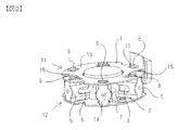
- FIG. 2 is a perspective view of the brush device showing a state in which the positive-side brush subassembly 11 and the negative-side brush subassembly 12 are coupled.
- FIG. 3 is a view of the positive brush subassembly 11 and the negative brush subassembly 12 as viewed from the brush holder mounting surface.
- FIG. 3A shows the positive brush subassembly 11 and FIG. ) Shows the negative-side brush subassembly 12.
- the lead-out direction of the positive-side brush lead wire 6 is, for example, the illustrated clockwise side of the brush holder 5 as shown in FIG. 3A when viewed from the brush holder mounting surface.
- the lead-out direction of the negative side brush lead wire 7 is, for example, the illustrated counterclockwise side of the brush holder 14 as shown in FIG. 3B when viewed from the brush holder mounting surface.
- the lead-out direction of the positive-side brush lead wire 6 with respect to the brush holder 5 and the lead-out direction of the negative-side brush lead wire 7 with respect to the brush holder 14 are The opposite is the case.
- the positive electrode side brush subassembly 11 and the negative electrode side brush subassembly 12 are couple
- the lead direction of the positive electrode side brush lead wire 6 and the lead direction of the negative electrode side brush lead wire 7 may be in the same direction.
- the brush device described above has the following operational effects.
- the brush device includes a positive electrode brush 3 that supplies power to the commutator, a brush holder 5 that holds the positive electrode brush 3, and a positive electrode side brush subassembly 11 having a positive electrode side plate 1 to which the brush holder 5 is attached.
- the positive electrode side brush subassembly 11 and the negative electrode side brush sub The assembly 12 is fixed or positioned with respect to each other.
- the positive electrode side brush subassembly 11 and the negative electrode side brush subassembly 12 can be assembled separately, and the space for assembling the brushes 3 and 4 and the brush holders 5 and 14 can be sufficiently secured.
- An excellent and inexpensive brush device can be provided.
- the positive electrode brush holder 5 has a hook portion 8 that engages with the negative electrode side plate 2
- the negative electrode brush holder 14 has a hook portion 8 that engages with the positive electrode side plate 1, and the positive electrode side plate 1
- the negative side plate 2 has a hole 13 that engages with the hook portion 8.
- the positive brush subassembly 11 and the negative brush subassembly 12 are engaged with the hook portion 8 of the brush holder 5 and the hole 13 of the negative plate 2, so that the hook portion 8 of the brush holder 14 and the positive plate 1
- the holes 13 are fixed or positioned to each other by engaging.
- the brush holder 5 is attached to one surface of the positive electrode side plate 1, and the brush holder 14 is attached to one surface of the negative electrode side plate 2, and the positive electrode side brush subassembly 11 and the negative electrode side brush subassembly 12.
- the one surface of the positive electrode side plate 1 and the one surface of the negative electrode side plate 2 face each other.
- the claw of the hook portion 8 protrudes toward the side opposite to the through holes 1a and 2a, but the protruding direction of the claw of the hook portion 8 is not limited to this.
- the claw of the hook portion 8 may protrude toward the through holes 1a and 2a, or may protrude in the circumferential direction centering on the through holes 1a and 2a.
- the number of claws of the hook portion 8 is not limited to one and may be plural.
- the hook of the hook portion 8 is It does not have to be.
- the positive-side brush subassembly 11 and the negative-side brush subassembly 12 are coupled by engaging the claws of the hook portion 8 and the hole 13 with each other.
- the hook portion 8 and the hole 13 are an example of a structure for connecting the positive electrode side brush subassembly 11 and the negative electrode side brush subassembly 12. Therefore, the structure for connecting the positive electrode side brush subassembly 11 and the negative electrode side brush subassembly 12 is not limited to the structure in which the hook portion 8 and the hole 13 are engaged.
- a claw may be provided on the positive electrode side plate 1 or the negative electrode side plate 2, and the claw and the claw of the hook portion 8 described above may be engaged.
- the number of the positive electrode brush 3 and the negative electrode side brush 4 is three, but the number of the positive electrode brush 3 and the negative electrode side brush 4 may be at least 1 or more.
- the present invention is not limited to the above-described embodiment, and other forms conceivable within the scope of the technical idea of the present invention are also included in the scope of the present invention as long as the characteristics of the present invention are not impaired. . Moreover, it is good also as a structure which combined the above-mentioned embodiment and a some modification.
Landscapes
- Engineering & Computer Science (AREA)
- Power Engineering (AREA)
- Motor Or Generator Current Collectors (AREA)
- Motor Or Generator Frames (AREA)
Abstract
組立作業性が良好なブラシ装置を提供する。 ブラシ装置は、整流子に給電する正極ブラシ、正極ブラシを保持する正極ブラシホルダ、および正極ブラシホルダが取り付けられる正極側プレートを有する正極側ブラシサブアッセンブリと、整流子に給電する負極ブラシ、負極ブラシを保持する負極ブラシホルダ、および負極ブラシホルダが取り付けられる負極側プレートを有する負極側ブラシサブアッセンブリとを備え、正極側ブラシサブアッセンブリと負極側ブラシサブアッセンブリとは、互いに固定もしくは位置決めされる。
Description
本発明は、電動機用ブラシ装置に関する。
近年、車両用の環境対応技術として、電動機は長寿命化や軽量化、ダウンサイジング化が推し進められている。たとえば、エンジンを始動する電動機においては、燃費改善を目的に、小型・軽量化や、アイドリングストップシステム対応のための長寿命化対応がなされている。たとえば、電動機のブラシ数は、従来2個、もしくは4個であったのに対し、小型・長寿命化対応として、6個、またはそれ以上に増やされている。ブラシ数の増加に伴ってブラシ装置の構成が複雑になることから、組立作業性が低下するおそれがある。そこで、2つの環状の印刷回路基板を外側に配し、絶縁材料からなる2つの案内板を内側に配し、リベット等によって2つの環状の印刷回路基板と2つの案内板とを結合したブラシ装置が知られている(特許文献1参照)。
しかしながら、公知の構成においては、2つの環状の印刷回路基板と絶縁材料からなる2つの案内板とが結合された後、ブラシ等が組みつけられる。しかし、環状の印刷回路基板および案内板が固定されているため、ブラシ等の組付けスペースが狭く、組立作業がし難い。
ブラシ装置は、整流子に給電する正極ブラシ、正極ブラシを保持する正極ブラシホルダ、および正極ブラシホルダが取り付けられる正極側プレートを有する正極側ブラシサブアッセンブリと、整流子に給電する負極ブラシ、負極ブラシを保持する負極ブラシホルダ、および負極ブラシホルダが取り付けられる負極側プレートを有する負極側ブラシサブアッセンブリとを備え、正極側ブラシサブアッセンブリと負極側ブラシサブアッセンブリとは、互いに固定もしくは位置決めされる。
本発明によれば、ブラシ装置の組立作業性が良好となる。
以下、図面を用いて本発明の一実施の形態を説明する。
図1は、本発明の装置の一例を示すブラシ装置の全体図であり、後述する正極側ブラシサブアッセンブリ11と負極側ブラシサブアッセンブリ12とを結合する前の状態を示している。本実施の形態のブラシ装置は、不図示の電動機の整流子へ給電するための装置であり、正極側ブラシサブアッセンブリ11と負極側ブラシサブアッセンブリ12とを備えている。正極側ブラシサブアッセンブリ11および負極側ブラシサブアッセンブリ12はそれぞれ独立して構成されている。
図1は、本発明の装置の一例を示すブラシ装置の全体図であり、後述する正極側ブラシサブアッセンブリ11と負極側ブラシサブアッセンブリ12とを結合する前の状態を示している。本実施の形態のブラシ装置は、不図示の電動機の整流子へ給電するための装置であり、正極側ブラシサブアッセンブリ11と負極側ブラシサブアッセンブリ12とを備えている。正極側ブラシサブアッセンブリ11および負極側ブラシサブアッセンブリ12はそれぞれ独立して構成されている。
正極側ブラシサブアッセンブリ11は、正極側プレート1と、正極側プレート1に固定された3つのブラシホルダ5と、ブラシホルダ5に収容された不図示のブラシばねと、ブラシホルダ5に収容された正極ブラシ3とを有する。正極側プレート1は、電力源のプラス側に接続される円盤状の部材であり、電動機の不図示の整流子が貫通する貫通孔1aが中央に設けられている。ブラシホルダ5は、不図示の整流子へ給電する正極ブラシ3を保持する樹脂製のブラシホルダである。本実施の形態では、3つのブラシホルダ5は、正極側プレート1の図1における下面に、貫通孔1aの周囲に貫通孔1aを中心として約120度毎の間隔でそれぞれ取り付けられている。すなわち、正極側プレート1は、ブラシホルダ5を介して正極ブラシ3を保持する。
正極ブラシ3は、ブラシホルダ5に保持されて、ブラシホルダ5内に設けられたブラシばねの付勢力によって組み立て用治具であるリング9に付勢されている。リング9は、貫通孔1aよりも僅かに小径の円筒である。正極ブラシ3と正極側プレート1とは、正極側ブラシリード線6によって接続されている。
正極側プレート1には、ブラシホルダ5を固定するための固定穴15が設けられている。固定穴15は、貫通孔1aを中心として約120度毎の間隔で3箇所に設けられている。固定穴15には、ブラシホルダ5の上面に設けられた後述するフック部8の爪が係合する。また、正極側プレート1には、隣り合う固定穴15同士の間に穴13が設けられている。穴13は、貫通孔1aを中心として約120度毎の間隔で3箇所に取り付けられている。固定穴15と穴13とは、たとえば、貫通孔1aを中心として約60度ずれて配置されている。
各ブラシホルダ5の上面および下面には、貫通孔1aとは反対側に向かって突出する爪を有するフック部8が設けられている。各ブラシホルダ5は、上側のフック部8の爪が正極側プレート1の固定穴15と係合することで正極側プレート1に固定されている。
負極側ブラシサブアッセンブリ12の構成も正極側ブラシサブアッセンブリ11と同様である。すなわち、負極側ブラシサブアッセンブリ12は、負極側プレート2と、負極側プレート2に固定された3つのブラシホルダ14と、ブラシホルダ14に収容されたブラシばね10と、ブラシホルダ14に収容された負極ブラシ4とを有する。負極側プレート2は、電力源のアース側に接続される円盤状の部材であり、電動機の不図示の整流子が貫通する貫通孔2aが中央に設けられている。ブラシホルダ14は、不図示の整流子へ給電する負極ブラシ4を保持する樹脂製のブラシホルダである。本実施の形態では、3つのブラシホルダ14は、負極側プレート2の図1における上面に、貫通孔2aの周囲に貫通孔2aを中心として約120度毎の間隔で計3個取り付けられている。すなわち、負極側プレート2は、ブラシホルダ14を介して負極ブラシ2を保持する。
負極ブラシ4は、ブラシホルダ14に保持されて、ブラシバネ10の付勢力によってリング9に付勢される。なお、負極側ブラシサブアッセンブリ12のリング9は、たとえば正極側ブラシサブアッセンブリ11のリング9と同一形状のものである。負極ブラシ4と負極側プレート2とは、負極側ブラシリード線7によって接続されている。
負極側プレート2には、正極側プレート1の固定穴15と同様の不図示の固定穴が設けられている。すなわち、固定穴は、貫通孔2aを中心として約120度毎の間隔で3箇所に設けられている。この固定穴には、ブラシホルダ14の下面に設けられた不図示のフック部の爪が係合する。また、負極側プレート2には、隣り合う固定穴同士の間に穴13が設けられている。穴13は、貫通孔2aを中心として約120度毎の間隔で3箇所に取り付けられている。固定穴と穴13とは、たとえば、貫通孔2aを中心として約60度ずれて配置されている。
各ブラシホルダ14の上面および下面には、ブラシホルダ5と同様に、貫通孔2aとは反対側に向かって突出する爪を有するフック部8が設けられている。各ブラシホルダ14は、下側のフック部8の爪が負極側プレート2の不図示の固定穴と係合することで負極側プレート2に固定もしくは位置決めされている。
このように構成される正極側ブラシサブアッセンブリ11と負極側ブラシサブアッセンブリ12とは、図1に示すように、正極側プレート1のブラシホルダ5が固定された面と、負極側プレート2のブラシホルダ14が固定された面とを対向させて互いに重ね合わせられる。そして、ブラシホルダ5の下側のフック部8の爪を負極側プレート2の穴13に挿入させて、爪と負極側プレート2の穴13とを互いに係合させる。同様に、図2に示すように、ブラシホルダ14の上側のフック部8の爪を正極側プレート1の穴13に挿入させて、爪と正極側プレート1の穴13とを互いに係合させる。これにより、正極側ブラシサブアッセンブリ11と負極側ブラシサブアッセンブリ12とが互い固定もしくは位置決めされる。なお、図2は、正極側ブラシサブアッセンブリ11と負極側ブラシサブアッセンブリ12とが結合された状態を示すブラシ装置の斜視図である。
なお、正極側ブラシサブアッセンブリ11と負極側ブラシサブアッセンブリ12とを結合する際、各ブラシサブアッセンブリ11,12のいずれか一方のリング9が他方のリング9によって押し出されて、ブラシ装置から外れる。これによって、正極ブラシ3および負極ブラシ4の両方がブラシ装置に残ったリング9に接触するようにブラシばねによって付勢される。ブラシ装置に残ったリング9は、ブラシ装置が電動機に装着される際等に、ブラシ装置から貫通孔1aまたは貫通孔2aを介して引き抜かれる。正極ブラシ3および負極ブラシ4は、ブラシばねによって整流子に圧接される。
図3は、正極側ブラシサブアッセンブリ11および負極側ブラシサブアッセンブリ12をブラシホルダ装着面から見たときの図であり、図3(a)は正極側ブラシサブアッセンブリ11を示し、図3(b)は負極側ブラシサブアッセンブリ12を示している。正極側ブラシリード線6の口出し方向は、ブラシホルダ装着面から見たとき、図3(a)に示すように、たとえばブラシホルダ5の図示時計方向側である。負極側ブラシリード線7の口出し方向は、ブラシホルダ装着面から見たとき、図3(b)に示すように、たとえばブラシホルダ14の図示反時計方向側である。
このように、本実施の形態では、ブラシホルダ装着面から見たときに、ブラシホルダ5に対する正極側ブラシリード線6の口出し方向と、ブラシホルダ14に対する負極側ブラシリード線7の口出し方向とが反対である。これにより、正極側ブラシサブアッセンブリ11と負極側ブラシサブアッセンブリ12とを結合した際に正極側ブラシリード線6と負極側ブラシリード線7とが対向せず、樹脂製のブラシホルダ5またはブラシホルダ14が介在する。なお、正極側ブラシリード線6、および負極側ブラシリード線7の少なくともいずれか一方を絶縁カバー等で絶縁処理すれば、正極側ブラシリード線6の口出し方向と負極側ブラシリード線7の口出し方向とが同方向となってもよい。
上述したブラシ装置では、次の作用効果を奏する。
(1)ブラシ装置は、整流子に給電する正極ブラシ3、正極ブラシ3を保持するブラシホルダ5、およびブラシホルダ5が取り付けられる正極側プレート1を有する正極側ブラシサブアッセンブリ11と、整流子に給電する負極ブラシ4、負極ブラシ4を保持するブラシホルダ14、およびブラシホルダ14が取り付けられる負極側プレート2を有する負極側ブラシサブアッセンブリ12とを備え、正極側ブラシサブアッセンブリ11と負極側ブラシサブアッセンブリ12とは、互いに固定もしくは位置決めされる。これにより、正極側ブラシサブアッセンブリ11と負極側ブラシサブアッセンブリ12とを別々に組み立てることができ、ブラシ3,4およびブラシホルダ5,14等を組み付けるスペースを十分に確保できるので、組立作業性に優れた安価なブラシ装置を提供できる。
(1)ブラシ装置は、整流子に給電する正極ブラシ3、正極ブラシ3を保持するブラシホルダ5、およびブラシホルダ5が取り付けられる正極側プレート1を有する正極側ブラシサブアッセンブリ11と、整流子に給電する負極ブラシ4、負極ブラシ4を保持するブラシホルダ14、およびブラシホルダ14が取り付けられる負極側プレート2を有する負極側ブラシサブアッセンブリ12とを備え、正極側ブラシサブアッセンブリ11と負極側ブラシサブアッセンブリ12とは、互いに固定もしくは位置決めされる。これにより、正極側ブラシサブアッセンブリ11と負極側ブラシサブアッセンブリ12とを別々に組み立てることができ、ブラシ3,4およびブラシホルダ5,14等を組み付けるスペースを十分に確保できるので、組立作業性に優れた安価なブラシ装置を提供できる。
(2)正極ブラシホルダ5は、負極側プレート2と係合するフック部8を有し、負極ブラシホルダ14は、正極側プレート1と係合するフック部8を有し、正極側プレート1は、フック部8と係合する穴13を有し、負極側プレート2は、フック部8と係合する穴13を有する。正極側ブラシサブアッセンブリ11と負極側ブラシサブアッセンブリ12とは、ブラシホルダ5のフック部8と負極側プレート2の穴13とが係合し、ブラシホルダ14のフック部8と正極側プレート1の穴13とが係合することで互いに固定もしくは位置決めされる。これにより、正極側ブラシサブアッセンブリ11と負極側ブラシサブアッセンブリ12とを互いに固定もしくは位置決めする構造が単純となるので、ブラシ装置のコスト増を抑制できる。また、正極側ブラシサブアッセンブリ11と負極側ブラシサブアッセンブリ12との結合作業が容易となる。
(3)ブラシホルダ5は、正極側プレート1の一方の面に取り付けられ、ブラシホルダ14は、負極側プレート2の一方の面に取り付けられ、正極側ブラシサブアッセンブリ11と負極側ブラシサブアッセンブリ12とが互いに固定もしくは位置決めされると、正極側プレート1の一方の面と負極側プレート2の一方の面とが対向する。これにより、ブラシ装置の正極側プレート1と負極側プレート2との距離を近づけられるので、ブラシ装置および電動機の小型化に資する。
---変形例---
(1)上述の説明では、フック部8の爪が貫通孔1a,2aとは反対側に向かって突出しているが、フック部8の爪の突出方向はこれに限定されない。たとえば、フック部8の爪が貫通孔1a,2aに向かって突出していてもよく、貫通孔1a,2aを中心とする周方向に突出していてもよい。また、フック部8の爪の数は1つに限らず、複数であってもよい。また、正極側ブラシサブアッセンブリ11と負極側ブラシサブアッセンブリ12の係合は、整流子中心軸に対し、軸方向固定もしくは位置決めがなくてもよい場合もあるため、このときフック部8の爪はなくてもよい。
(1)上述の説明では、フック部8の爪が貫通孔1a,2aとは反対側に向かって突出しているが、フック部8の爪の突出方向はこれに限定されない。たとえば、フック部8の爪が貫通孔1a,2aに向かって突出していてもよく、貫通孔1a,2aを中心とする周方向に突出していてもよい。また、フック部8の爪の数は1つに限らず、複数であってもよい。また、正極側ブラシサブアッセンブリ11と負極側ブラシサブアッセンブリ12の係合は、整流子中心軸に対し、軸方向固定もしくは位置決めがなくてもよい場合もあるため、このときフック部8の爪はなくてもよい。
(2)上述の説明では、フック部8の爪と穴13とを互いに係合させることで正極側ブラシサブアッセンブリ11と負極側ブラシサブアッセンブリ12とを結合するように構成した。しかし、フック部8および穴13は、正極側ブラシサブアッセンブリ11と負極側ブラシサブアッセンブリ12とを結合するための構造としての一例である。したがって、正極側ブラシサブアッセンブリ11と負極側ブラシサブアッセンブリ12とを結合するための構造は、上述したフック部8と穴13とを係合する構造に限らない。たとえば、穴13に代えて、正極側プレート1や負極側プレート2に爪を設け、この爪と上述したフック部8の爪とを係合させるように構成してもない。なお、正極側プレート1と負極側プレート2とを互いに電気的に絶縁する必要があることから、上述した実施の形態のように、正極側プレート1と負極側プレート2との間に樹脂製のブラシホルダ5,14を介在させて、ブラシホルダ5,14を介して正極側プレート1と負極側プレート2とを結合することが望ましい。
(3)上述の説明では、正極ブラシ3および負極側ブラシ4の数がそれぞれ3であったが、正極ブラシ3および負極側ブラシ4の数は、少なくともそれぞれ1以上であればよい。
本発明は、上記の実施形態に限定されるものではなく、本発明の特徴を損なわない限り、本発明の技術思想の範囲内で考えられるその他の形態についても、本発明の範囲内に含まれる。また、上述の実施形態と複数の変形例を組み合わせた構成としてもよい。
1;正極側プレート、2;負極側プレート、3;正極ブラシ、4;負極ブラシ、5,14;ブラシホルダ、6;正極ブラシリード線、7;負極ブラシリード線、8;フック部、9;リング、10;ブラシばね、11;正極側ブラシサブアッセンブリ、12;負極側ブラシサブアッセンブリ、13;穴
Claims (3)
- 整流子に給電する正極ブラシ、前記正極ブラシを保持する正極ブラシホルダ、および前記正極ブラシホルダが取り付けられる正極側プレートを有する正極側ブラシサブアッセンブリと、
前記整流子に給電する負極ブラシ、前記負極ブラシを保持する負極ブラシホルダ、および前記負極ブラシホルダが取り付けられる負極側プレートを有する負極側ブラシサブアッセンブリとを備え、
前記正極側ブラシサブアッセンブリと前記負極側ブラシサブアッセンブリとは、互いに固定もしくは位置決めされるブラシ装置、およびこれを用いた電動機。 - 請求項1に記載のブラシ装置、およびこれを用いた電動機において、
前記正極ブラシホルダは、前記負極側プレートと係合する正極側ホルダ係合部を有し、
前記負極ブラシホルダは、前記正極側プレートと係合する負極側ホルダ係合部を有し、
前記正極側プレートは、前記負極側ホルダ係合部と係合する正極側プレート係合部を有し、
前記負極側プレートは、前記正極側ホルダ係合部と係合する負極側プレート係合部を有し、
前記正極側ブラシサブアッセンブリと前記負極側ブラシサブアッセンブリとは、前記正極側ホルダ係合部と前記負極側プレート係合部とが係合し、前記負極側ホルダ係合部と前記正極側プレート係合部とが係合することで互いに固定もしくは位置決めされるブラシ装置、およびこれを用いた電動機。 - 請求項1または請求項2に記載のブラシ装置、およびこれを用いた電動機において、
前記正極ブラシホルダは、前記正極側プレートの一方の面に取り付けられ、
前記負極ブラシホルダは、前記負極側プレートの一方の面に取り付けられ、
前記正極側ブラシサブアッセンブリと前記負極側ブラシサブアッセンブリとが互いに固定もしくは位置決めされると、前記正極側プレートの前記一方の面と前記負極側プレートの前記一方の面とが対向するブラシ装置、およびこれを用いた電動機。
Priority Applications (2)
| Application Number | Priority Date | Filing Date | Title |
|---|---|---|---|
| CN201680049209.4A CN107925316B (zh) | 2015-08-27 | 2016-07-27 | 带电刷装置的电动机 |
| JP2017536701A JP6484342B2 (ja) | 2015-08-27 | 2016-07-27 | 電動機用ブラシ装置 |
Applications Claiming Priority (2)
| Application Number | Priority Date | Filing Date | Title |
|---|---|---|---|
| JP2015-167356 | 2015-08-27 | ||
| JP2015167356 | 2015-08-27 |
Publications (1)
| Publication Number | Publication Date |
|---|---|
| WO2017033655A1 true WO2017033655A1 (ja) | 2017-03-02 |
Family
ID=58099894
Family Applications (1)
| Application Number | Title | Priority Date | Filing Date |
|---|---|---|---|
| PCT/JP2016/071952 Ceased WO2017033655A1 (ja) | 2015-08-27 | 2016-07-27 | ブラシ装置付き電動機 |
Country Status (3)
| Country | Link |
|---|---|
| JP (1) | JP6484342B2 (ja) |
| CN (1) | CN107925316B (ja) |
| WO (1) | WO2017033655A1 (ja) |
Cited By (1)
| Publication number | Priority date | Publication date | Assignee | Title |
|---|---|---|---|---|
| JP2019154096A (ja) * | 2018-02-28 | 2019-09-12 | 株式会社デンソー | ブラシ保持構造 |
Citations (3)
| Publication number | Priority date | Publication date | Assignee | Title |
|---|---|---|---|---|
| JPH0556596A (ja) * | 1991-08-22 | 1993-03-05 | Nippondenso Co Ltd | ブラシ保持装置 |
| JP2005020910A (ja) * | 2003-06-26 | 2005-01-20 | Aisin Seiki Co Ltd | 直流機のブラシ保持装置 |
| JP2014087102A (ja) * | 2012-10-19 | 2014-05-12 | Asmo Co Ltd | ブラシ装置、ブラシ装置の製造方法及び直流モータ |
Family Cites Families (3)
| Publication number | Priority date | Publication date | Assignee | Title |
|---|---|---|---|---|
| DE102007059555A1 (de) * | 2007-12-11 | 2009-06-18 | Hoffmann & Co. Elektrokohle Ag | Bürstenaggregat für eine elektrische Maschine, Feder- und Dichtungsanordnung für dasselbe, sowie Verfahren zu seiner Herstellung |
| DE102011017526A1 (de) * | 2011-04-26 | 2012-10-31 | Robert Bosch Gmbh | Bürstenanordnung in einer Kommutierungseinrichtung |
| CN203896124U (zh) * | 2014-06-17 | 2014-10-22 | 浙江瑞申汽配有限公司 | 电刷接触力可调式汽车起动机电刷总成 |
-
2016
- 2016-07-27 CN CN201680049209.4A patent/CN107925316B/zh active Active
- 2016-07-27 WO PCT/JP2016/071952 patent/WO2017033655A1/ja not_active Ceased
- 2016-07-27 JP JP2017536701A patent/JP6484342B2/ja active Active
Patent Citations (3)
| Publication number | Priority date | Publication date | Assignee | Title |
|---|---|---|---|---|
| JPH0556596A (ja) * | 1991-08-22 | 1993-03-05 | Nippondenso Co Ltd | ブラシ保持装置 |
| JP2005020910A (ja) * | 2003-06-26 | 2005-01-20 | Aisin Seiki Co Ltd | 直流機のブラシ保持装置 |
| JP2014087102A (ja) * | 2012-10-19 | 2014-05-12 | Asmo Co Ltd | ブラシ装置、ブラシ装置の製造方法及び直流モータ |
Cited By (1)
| Publication number | Priority date | Publication date | Assignee | Title |
|---|---|---|---|---|
| JP2019154096A (ja) * | 2018-02-28 | 2019-09-12 | 株式会社デンソー | ブラシ保持構造 |
Also Published As
| Publication number | Publication date |
|---|---|
| CN107925316B (zh) | 2020-01-14 |
| JP6484342B2 (ja) | 2019-03-13 |
| CN107925316A (zh) | 2018-04-17 |
| JPWO2017033655A1 (ja) | 2018-02-15 |
Similar Documents
| Publication | Publication Date | Title |
|---|---|---|
| CN105090099B (zh) | 吊扇马达 | |
| JP3766129B2 (ja) | 電動機用の回転子 | |
| CN110892610A (zh) | 电动工具 | |
| US8427027B2 (en) | Brush unit for an electric machine, spring and seal arrangement for the same, and method for the production thereof | |
| CN103650259A (zh) | 换向装置中的电刷组件 | |
| CN102414968B (zh) | 电动马达及带减速器的电动机 | |
| JP2006517776A (ja) | 電気機械の整流子 | |
| CN104904104A (zh) | 用于励磁线圈的线圈架,励磁线圈结构,隔离罩,定子装置以及用于同极电机的定子 | |
| CN102210084A (zh) | 用于电动发电机的电刷架组件 | |
| JP6484342B2 (ja) | 電動機用ブラシ装置 | |
| CN106876644A (zh) | 一种电连接板 | |
| CN106165216A (zh) | 包括刷握支撑板和刷握的热机起动器 | |
| US8937423B2 (en) | Disk motor and electric power tool | |
| JP2013005705A (ja) | ポンプ用直流電動機 | |
| JP5619250B2 (ja) | 車両用交流発電機の整流装置 | |
| JPWO2006120934A1 (ja) | 電動モータにおけるブラシホルダ | |
| JP2010016993A (ja) | 高速スピンドルモータ | |
| JP6510881B2 (ja) | 電動モータ | |
| KR20200052603A (ko) | 버스바의 결합구조 | |
| JP2006121805A (ja) | ブラシ装置 | |
| JPH0746058Y2 (ja) | 電動工具の内部配線 | |
| JPH089598A (ja) | 電装用モータのリード線接続部構造 | |
| KR101048756B1 (ko) | 모터 장치 | |
| JP6584659B2 (ja) | 車両用回転電機 | |
| KR101916397B1 (ko) | 차량용 배터리 단자 결합구 |
Legal Events
| Date | Code | Title | Description |
|---|---|---|---|
| 121 | Ep: the epo has been informed by wipo that ep was designated in this application |
Ref document number: 16839002 Country of ref document: EP Kind code of ref document: A1 |
|
| ENP | Entry into the national phase |
Ref document number: 2017536701 Country of ref document: JP Kind code of ref document: A |
|
| NENP | Non-entry into the national phase |
Ref country code: DE |
|
| 122 | Ep: pct application non-entry in european phase |
Ref document number: 16839002 Country of ref document: EP Kind code of ref document: A1 |