WO2017033587A1 - 蓄電池システム制御方法 - Google Patents
蓄電池システム制御方法 Download PDFInfo
- Publication number
- WO2017033587A1 WO2017033587A1 PCT/JP2016/070044 JP2016070044W WO2017033587A1 WO 2017033587 A1 WO2017033587 A1 WO 2017033587A1 JP 2016070044 W JP2016070044 W JP 2016070044W WO 2017033587 A1 WO2017033587 A1 WO 2017033587A1
- Authority
- WO
- WIPO (PCT)
- Prior art keywords
- storage battery
- power
- battery system
- units
- control method
- Prior art date
- Legal status (The legal status is an assumption and is not a legal conclusion. Google has not performed a legal analysis and makes no representation as to the accuracy of the status listed.)
- Ceased
Links
Images


Classifications
-
- H—ELECTRICITY
- H02—GENERATION; CONVERSION OR DISTRIBUTION OF ELECTRIC POWER
- H02J—ELECTRIC POWER NETWORKS; CIRCUIT ARRANGEMENTS OR SYSTEMS FOR SUPPLYING OR DISTRIBUTING ELECTRIC POWER; SYSTEMS FOR STORING ELECTRIC ENERGY
- H02J3/00—Circuit arrangements for AC mains or AC distribution networks
- H02J3/28—Arrangements for balancing of the load in networks by storage of energy
- H02J3/32—Arrangements for balancing of the load in networks by storage of energy using batteries or super capacitors with converting means
-
- H—ELECTRICITY
- H02—GENERATION; CONVERSION OR DISTRIBUTION OF ELECTRIC POWER
- H02J—ELECTRIC POWER NETWORKS; CIRCUIT ARRANGEMENTS OR SYSTEMS FOR SUPPLYING OR DISTRIBUTING ELECTRIC POWER; SYSTEMS FOR STORING ELECTRIC ENERGY
- H02J7/00—Circuit arrangements for charging or discharging batteries or for supplying loads from batteries
- H02J7/50—Circuit arrangements for charging or discharging batteries or for supplying loads from batteries acting upon multiple batteries simultaneously or sequentially
-
- H—ELECTRICITY
- H02—GENERATION; CONVERSION OR DISTRIBUTION OF ELECTRIC POWER
- H02J—ELECTRIC POWER NETWORKS; CIRCUIT ARRANGEMENTS OR SYSTEMS FOR SUPPLYING OR DISTRIBUTING ELECTRIC POWER; SYSTEMS FOR STORING ELECTRIC ENERGY
- H02J7/00—Circuit arrangements for charging or discharging batteries or for supplying loads from batteries
- H02J7/80—Circuit arrangements for charging or discharging batteries or for supplying loads from batteries including monitoring or indicating arrangements
- H02J7/82—Control of state of charge [SOC]
-
- H—ELECTRICITY
- H02—GENERATION; CONVERSION OR DISTRIBUTION OF ELECTRIC POWER
- H02J—ELECTRIC POWER NETWORKS; CIRCUIT ARRANGEMENTS OR SYSTEMS FOR SUPPLYING OR DISTRIBUTING ELECTRIC POWER; SYSTEMS FOR STORING ELECTRIC ENERGY
- H02J7/00—Circuit arrangements for charging or discharging batteries or for supplying loads from batteries
- H02J7/855—Circuit arrangements for charging or discharging batteries or for supplying loads from batteries with circuits adapted for supplying loads from the battery
-
- H—ELECTRICITY
- H02—GENERATION; CONVERSION OR DISTRIBUTION OF ELECTRIC POWER
- H02J—ELECTRIC POWER NETWORKS; CIRCUIT ARRANGEMENTS OR SYSTEMS FOR SUPPLYING OR DISTRIBUTING ELECTRIC POWER; SYSTEMS FOR STORING ELECTRIC ENERGY
- H02J7/00—Circuit arrangements for charging or discharging batteries or for supplying loads from batteries
- H02J7/90—Regulation of charging or discharging current or voltage
- H02J7/96—Regulation of charging or discharging current or voltage in response to battery voltage
Definitions
- the present invention relates to a storage battery system control method suitable for use in frequency control, for example.
- the frequency control refers to various operations for frequency control including an ancillary service, for example, for the purpose of suppressing frequency fluctuation of the AC power system. The same applies hereinafter.
- the frequency control for suppressing the frequency fluctuation of the AC power system is described in, for example, Japanese Patent Application Laid-Open No. 2012-16077.
- the frequency control device described in this publication performs charge / discharge control of a plurality of secondary batteries connected to the AC power system according to fluctuations in demand of the AC power system so that the frequency of the AC power system becomes the reference frequency. To control. In particular, the charging depth of the secondary battery is corrected so that the charging depth of the secondary battery is 50%.
- the capacity of the storage battery is required to cope with frequency control that requires a large amount of power. It is necessary to increase. In that case, there may be a case where the economy is impaired by having an excessive battery capacity with respect to the required amount of power.
- the present invention has been made in consideration of such problems, and an object thereof is to provide a storage battery system control method that achieves the following effects. (1) Basically having a large capacity, it can easily cope with frequency control that requires a large amount of power, and can cover a wide range of short-time high-power operations to long-term large-capacity operations. (2) It is possible to realize frequency control that can flexibly cope with various operations.
- a storage battery system control method combines a high-capacity storage battery system capable of storing a large amount of power with a high-power storage battery system capable of outputting a large amount of power in a short time, thereby changing the frequency of an AC power system.
- the operation means for frequency control has at least the following steps.
- (B) Electric power necessary for frequency control for suppressing the frequency fluctuation is supplied to the SOC acquisition step.
- the power required for the frequency control is apportioned according to each SOC value obtained in the SOC acquisition step, and the large-capacity storage battery system and the large power storage system You may allocate to an electric power storage battery system.
- the power allocation step when the power required for the frequency control is power in the discharge direction, the power allocation step preferentially allocates the power in the discharge direction to the large-capacity storage battery system, and the frequency When the power required for the control is the power in the charging direction, the power allocation step may preferentially allocate the power in the charging direction to the high power storage battery system.
- the power allocation step uses the power in the discharge direction as the power storage battery system and the power storage battery system.
- the power required for the frequency control is preferentially assigned to the storage battery system having the higher SOC value
- the power allocation step uses the power in the charging direction as the high capacity storage battery system.
- the storage battery system with the lower SOC value may be preferentially assigned.
- a depth management step in which the stored energy of the large-capacity storage battery system is interchanged with the large-power storage battery system, and the depth of the large-power storage battery system is maintained in an appropriate range.
- a distributed control step having a plurality of units in which the large-capacity storage battery system and the large-power storage battery system are combined, and allocating power necessary for the frequency control to two or more units.
- the power allocation step of each unit includes the power allocated in the distributed control step in accordance with each SOC value obtained in the SOC acquisition step, and the large capacity storage battery system and the You may allocate to a high power storage battery system.
- the distributed control step when the power required for the frequency control is power in the discharge direction, at least the SOC value of the large-capacity storage battery system is within an appropriate range among the plurality of units 2
- the power necessary for frequency control may be distributed and allocated to the above units with priority.
- the distributed control step during the period when one or more units among the plurality of units are performing maintenance operation on the large-capacity storage battery system, the one or more units are set to the frequency control. You may exclude from the allocation object of required electric power.
- a depth calculation correction process refers to a process of periodically charging or discharging the large-capacity storage battery system to a specific depth range and correcting the depth calculation parameter of the large-capacity storage battery system based on the voltage characteristics.
- the SOC value of the large power storage battery system is two or more low.
- the power necessary for the frequency control may be preferentially distributed and assigned to the units.
- the frequency control is performed on the one or more units while the one or more units are performing maintenance operation on the high power storage battery system. May be excluded from the target of power allocation required for.
- the maintenance operation for the large power storage battery system for example, there is a process similar to the depth calculation correction process described above.
- the unit unit At least one of the timing of allocating power and the gain of the allocated power may be changed.
- the SOC value of the large capacity storage battery system is not within an appropriate range.
- the storage battery system control method has the following effects. (1) Basically having a large capacity, it can easily cope with frequency control that requires a large amount of power, and can cover a wide range of short-time high-power operations to long-term large-capacity operations. (2) It is possible to realize frequency control that can flexibly cope with various operations.
- FIG. 1 is a block diagram showing a configuration of a first hybrid storage battery system to which the storage battery system control method (first storage battery system control method) according to the first embodiment is applied.
- FIG. 2 is a flowchart showing the first storage battery system control method.
- FIG. 3A is a waveform diagram showing an example of a discharge power waveform due to discharge of only the large capacity storage battery system.
- FIG. 3B is a waveform diagram illustrating an example of a discharge power waveform due to discharge of the large-capacity storage battery system and the large-power storage battery system.
- FIG. 4A is a waveform diagram showing an example of a charging power waveform by charging only the high-power storage battery system.
- FIG. 4B is a waveform diagram showing an example of a charging power waveform due to charging of the large-capacity storage battery system and the large-power storage battery system.
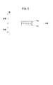
- FIG. 5 is a waveform diagram showing an example of a power waveform when the storage energy of the large-capacity storage battery system is accommodated in the high-power storage battery system.
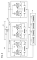
- FIG. 6 is a block diagram showing a configuration of a second hybrid storage battery system to which the storage battery system control method (second storage battery system control method) according to the second embodiment is applied.
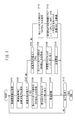
- FIG. 7 is a flowchart showing a second storage battery system control method.
- the first hybrid storage battery system 10A includes a large capacity storage battery system 12a capable of storing a large amount of power, a large power storage battery system 12b capable of outputting a large amount of power in a short time, and these large capacity storage battery systems. 12a and the high-power storage battery system 12b.
- the large-capacity storage battery system 12a includes a large-capacity storage battery 16a and a first PCS 18a (Power Conversion System) for the large-capacity storage battery 16a.
- a large-capacity storage battery 16a and a first PCS 18a (Power Conversion System) for the large-capacity storage battery 16a.
- PCS 18a Power Conversion System
- the large-capacity storage battery 16a examples include a sodium-sulfur battery (hereinafter referred to as a NaS battery).
- the first PCS 18a includes a first AC / DC converter 20a, and charges and discharges the large-capacity storage battery 16a in accordance with a charge command and a discharge command from the control device 14.
- the large capacity storage battery 16a is connected to the DC terminal of the first AC / DC converter 20a in the first PCS 18a.
- a wiring 24 is connected to the AC end of the first PCS 18a via a first transformer 22a.
- the wiring 24 is connected to the bus 26 of the AC power system.
- a frequency measuring device 30 that detects the frequency (system frequency f) of the power flowing through the bus 26 is installed on the connection line 28 that connects the wiring 24 and the bus 26.
- the high power storage battery system 12b includes a high power storage battery 16b and a second PCS 18b for the high power storage battery 16b.
- Examples of the high power storage battery 16b include a lithium ion battery.
- the second PCS 18b has a second AC / DC converter 20b, and charges and discharges the high-power storage battery 16b in accordance with a charge command and a discharge command from the control device 14.
- the large power storage battery 16b is connected to the DC terminal of the second AC / DC converter 20b in the second PCS 18b.
- a wiring 24 is connected to the AC terminal of the second PCS 18b via a second transformer 22b.
- the first storage unit 16a for detecting the charging depth (SOC value) of the large-capacity storage battery 16a is installed in the large-capacity storage battery 16a.
- the large power storage battery 16b is provided with a second depth calculation device 32b that detects the charging depth (SOC value) of the large power storage battery 16b. Output values from the first depth calculation device 32 a and the second depth calculation device 32 b are supplied to the control device 14.
- the control device 14 includes a power calculation unit 34, an SOC acquisition unit 36, a power allocation processing unit 38, a storage battery driving unit 40, and a depth management unit 42.
- the power calculation unit 34 generates power necessary for frequency control for suppressing frequency fluctuation based on the difference between the frequency (system frequency f) measured by the frequency measuring device 30 and a preset reference frequency fb. Calculate. In this case, if system frequency f ⁇ reference frequency fb ⁇ 0, positive direction power (discharge direction power) is calculated, and if system frequency f ⁇ reference frequency fb> 0, negative direction power (charge direction). Power) is calculated.
- the SOC acquisition unit 36 acquires the current SOC value of the large-capacity storage battery system 12a and the current SOC value of the large-power storage battery system 12b based on the output values from the first depth calculation device 32a and the second depth calculation device 32b. To do.
- the power allocation processing unit 38 supplies the power obtained by the calculation in the power calculation unit 34 to the large-capacity storage battery system 12a and the large power storage battery system 12b according to each SOC value obtained in the SOC acquisition unit 36. assign.
- the storage battery driving unit 40 drives the large-capacity storage battery system 12a, the large-power storage battery system 12b, or the large-capacity storage battery system 12a and the large-power storage battery system 12b, and charges or discharges the allocated power.
- the depth management unit 42 integrates the storage energy of the large-capacity storage battery system 12a into the large-power storage battery system 12b, and keeps the depth of the large-power storage battery system 12b within an appropriate range.
- This power allocation is performed in two stages.
- power is allocated by any one of three methods.
- the assignment in the first stage is corrected.
- the electric power necessary for frequency control is apportioned according to each SOC value obtained by the SOC acquisition unit 36 and assigned to the large capacity storage battery system 12a and the large power storage battery system 12b.
- the power required for frequency control is the discharge power Pd
- the SOC value of the large-capacity storage battery system 12a is Sa
- the SOC value of the large-power storage battery system 12b is Sb
- the electric power Pda is Pd ⁇ ⁇ Sa / (Sa + Sb) ⁇
- the power Pca allocated to the large-capacity storage battery system 12a is obtained by replacing the charging depth SOC (Sa, Sb) with the discharging depth DOD (Da, Db).
- Pca Pc ⁇ ⁇ Da / (Da + Db) ⁇
- the power Pd in the discharge direction is preferentially assigned to the large-capacity storage battery system 12a. That is, the power Pda allocated to the large-capacity storage battery system 12a is set as the power Pd.
- the power Pc in the charging direction is preferentially assigned to the high power storage battery system 12b. That is, the power Pca allocated to the large power storage battery system 12b is set as the power Pc.
- the electric power Pd in the discharging direction when the electric power required for frequency control is the electric power Pd in the discharging direction, the electric power Pd in the discharging direction is used as the storage battery having the higher SOC value of the large capacity storage battery system 12a and the large electric power storage battery system 12b. Assign to the system.
- the power required for frequency control is the power Pc in the charging direction
- the power Pc in the charging direction is transferred to the storage battery system with the lower SOC value of the large capacity storage battery system 12a and the large power storage battery system 12b. assign.
- the discharge power allocated to the large capacity storage battery system 12a is Pda
- the discharge power allocated to the large power storage battery system 12b is Pdb
- the correction coefficient kd1 (0 ⁇ kd1 ⁇ 1) is added to the discharge power Pda. A discharge power that is multiplied and does not deviate from an appropriate range narrower than the allowable range is assigned.
- the charging power allocated to the large capacity storage battery system 12a is Pca
- the charging power allocated to the large power storage battery system 12b is Pcb
- the charging power Pcb has a correction coefficient kc2 (0 ⁇ kc2 ⁇ 1). Charging power that does not deviate from an appropriate range narrower than the allowable range by multiplication is assigned.
- step S ⁇ b> 1 of FIG. 2 the power calculation unit 34 acquires the system frequency f measured by the frequency measuring device 30.
- step S2 the power calculation unit 34 calculates power necessary for frequency control for suppressing frequency fluctuation based on the difference between the system frequency f and a preset reference frequency fb.
- step S3 the power allocation processing unit 38 determines whether or not the difference between the system frequency f and the reference frequency fb is negative, that is, whether or not the power necessary for frequency control is power in the discharge direction.
- the process proceeds to the next step S4, and the SOC acquisition unit 36 acquires the current SOC value Sa of the large capacity storage battery system 12a and the current SOC value Sb of the large power storage battery system 12b.
- step S5 the power allocation processing unit 38 allocates the discharge power Pd in the first stage described above.
- the discharge power Pda assigned to the large capacity storage battery system 12a is Pd ⁇ ⁇ Sa / (Sa + Sb) ⁇
- the discharge power Pdb assigned to the large power storage battery system 12b is Pd ⁇ ⁇ Sb. / (Sa + Sb) ⁇ .
- the power Pda allocated to the large-capacity storage battery system 12a is set as the power Pd.
- the power Pd is allocated to the storage battery system having the higher SOC value out of the large capacity storage battery system 12a and the large power storage battery system 12b.
- step S6 the power allocation processing unit 38 performs allocation in the second stage described above.
- Pdb Pdm2.
- step S7 the storage battery driving unit 40 drives only the large-capacity storage battery system 12a, or the large-capacity storage battery system 12a and the large-power storage battery system 12b, and discharges the allocated power.
- the storage battery drive unit 40 outputs a discharge command to the first PCS 18a.
- This discharge command includes information on the discharge power Pda assigned to the large-capacity storage battery system 12a.
- the storage battery drive part 40 will output a discharge command with respect to 2nd PCS18b, if the discharge power allocated to the high power storage battery system 12b is larger than 0W.
- This discharge command includes information on the discharge power Pdb assigned to the large power storage battery system 12b.
- the first PCS 18a discharges the large-capacity storage battery 16a based on a discharge command from the storage battery drive unit 40, and outputs power corresponding to the discharge power Pda to the bus 26 side.
- the second PCS 18b discharges the large power storage battery 16b and outputs power corresponding to the discharge power Pdb to the bus 26 side.
- both the large-capacity storage battery 16a and the large-power storage battery 16b are driven to discharge, and the power in the discharge direction necessary for frequency control is large. Discharge power obtained by adding the discharge power Pda by the capacity storage battery system 12a and the discharge power Pdb by the large power storage battery system 12b is supplied to the bus 26 side.
- step S3 If it is determined in step S3 described above that the power necessary for frequency control is not the power in the discharge direction, the process proceeds to step S8, and the power allocation processing unit 38 determines that the difference between the system frequency f and the reference frequency fb is positive. It is determined whether there is power, that is, whether the power required for frequency control is power in the charging direction.
- step S9 If it is the electric power of a charge direction, it will progress to step S9 and the SOC acquisition part 36 will acquire the present SOC value Sa of the large capacity storage battery system 12a, and the present SOC value Sb of the large power storage battery system 12b.
- step S10 the power allocation processing unit 38 allocates the charging power Pc in the first stage described above.
- the charging power Pca allocated to the large capacity storage battery system 12a is Pc ⁇ ⁇ Da / (Da + Db) ⁇
- the charging power Pcb allocated to the large power storage battery system 12b is Pc ⁇ ⁇ Db / (Da + Db) ⁇ .
- the power Pcb allocated to the large power storage battery system 12b is set as the power Pc.
- the power allocated to the storage battery system having the lower SOC value of the large capacity storage battery system 12a and the large power storage battery system 12b is set as the power Pc.
- step S11 the power allocation processing unit 38 performs allocation in the second stage described above.
- the correction coefficient kc2 (0 ⁇ kc2 ⁇ 1) is added to the charging power Pcb. Multiply the charge power that does not deviate from the appropriate range.
- Pca Pcm1.
- step S12 the storage battery driving unit 40 drives only the large power storage battery system 12b, or the large capacity storage battery system 12a and the large power storage battery system 12b, and charges the allocated power.
- the storage battery drive unit 40 outputs a charge command to the second PCS 18b.
- This charging command includes information on the charging power Pcb assigned to the large power storage battery system 12b.
- the storage battery drive part 40 will output a charge command with respect to 1st PCS18a, if the charging power allocated to the large capacity storage battery system 12a is larger than 0W.
- This charging command includes information on the charging power Pca allocated to the large-capacity storage battery system 12a.
- 2nd PCS18b charges the high power storage battery 16b based on the charge command from the storage battery drive part 40, and inputs the electric power equivalent to charging power Pcb from the bus-line 26 side to the high power storage battery 16b.
- the first PCS 18a charges the large capacity storage battery 16a and inputs power corresponding to the charging power Pca from the bus 26 side to the large capacity storage battery 16a.
- both the large-capacity storage battery 16a and the large-power storage battery 16b are driven to charge, and the power in the charging direction necessary for frequency control is large.
- Charging power Pca by the capacity storage battery system 12a is supplied to the large capacity storage battery 16a
- charging power Pcb by the large power storage battery system 12b is supplied to the large power storage battery 16b.
- step S8 When it is determined in step S8 described above that the electric power is not in the charging direction, that is, when it is determined that the frequency control is not necessary, the process proceeds to step S13, and the SOC acquisition unit 36 determines the current power of the large power storage battery system 12b. The SOC value Sb is obtained.
- step S14 the depth management unit 42 determines whether or not the SOC value Sb of the large power storage battery system 12b is out of the appropriate range.
- step S15 the stored energy of the large-capacity storage battery system 12a is passed to the high-power storage battery system 12b, and the depth of the large-power storage battery system 12b is maintained in the appropriate range.
- the discharge power Pda is determined such that the SOC value Sa of the large-capacity storage battery system 12a does not deviate from the appropriate range.
- the storage battery drive part 40 outputs a discharge command to 1st PCS18a, and outputs a charge command to 2nd PCS18b.
- the discharge command output to the first PCS 18a includes information on the obtained discharge power Pda
- the charge command output to the second PCS 18b includes information on the charge power Pcb equivalent to the obtained discharge power Pda.
- step S7 When the process in step S7, step S12, or step S15 described above is completed, or when it is determined in step S14 that the SOC value Sb does not deviate from the appropriate range, the process proceeds to the next step S16, and the first step It is determined whether or not there is a termination request (power cut, maintenance operation, etc.) to the hybrid storage battery system 10A. If there is no end request, the process returns to step S1, and the processes after step S1 are repeated. If there is a termination request, the processing operation in the first hybrid storage battery system 10A is terminated.
- a termination request power cut, maintenance operation, etc.
- the maintenance operation includes depth calculation correction processing for the large-capacity storage battery system 12a.
- the depth calculation correction process is a process of periodically charging or discharging the large capacity storage battery system 12a to a specific depth range and correcting the depth calculation parameter of the large capacity storage battery system 12a based on the voltage characteristics. The same correction process is performed in the maintenance for the large power storage battery system 12b.
- the first storage battery system control method has at least the following operational effects.
- the large-capacity storage battery system 12a cannot supply (discharge) electric power that exceeds the rated output, it is necessary to increase the storage battery capacity when used for frequency control that requires large electric power.
- the high-power storage battery system 12b since the high-power storage battery system 12b is connected in parallel to the large-capacity storage battery system 12a, it can cover a wide range of short-time high-power operation to long-time large-capacity operation and flexibly handle various operations. Possible frequency control can be realized.
- the large power storage battery system 12b is always kept in a depth range in which both the positive and negative directions can be output with sufficient margins on both the output and capacity sides, but depth management is difficult due to the small capacity.
- the storage energy from the large-capacity storage battery 16a is automatically interchanged so as to maintain the depth of the large-power storage battery 16b in an appropriate range, and the depth is adjusted appropriately. The depth management of the existing large power storage battery 16b becomes easy.
- the large-capacity storage battery system 12 a and the large-power storage battery system use the electric power obtained by the calculation in the electric power calculation unit 34 according to the SOC values Sa and Sb obtained in the SOC acquisition unit 36. 12b is assigned. Since the input / output of the storage battery is restricted by the SOC state of the storage battery, the charge / discharge control is determined on the basis of the SOC state, so that the large capacity storage battery system 12a and the large power storage battery system 12b are appropriately charged / discharged. Can be controlled.
- the large power storage battery system 12b In frequency control, in a region where high output is required for a short time, the large power storage battery system 12b is mainly operated, and the large capacity storage battery system 12a performs long-term order input / output over a minute unit or SOC management of the large power storage battery system 12b. It is possible to construct a highly rational system.
- a hybrid storage battery system (hereinafter referred to as a second hybrid storage battery system 10B) to which a storage battery system control method according to the second embodiment (hereinafter referred to as a second storage battery system control method) is applied will be described with reference to FIGS. This will be described with reference to FIG.
- the second hybrid storage battery system 10 ⁇ / b> B includes a plurality of units 50 and a master controller 52 that controls the plurality of units 50 in an integrated manner.
- Each unit 50 has the same configuration as that of the first hybrid storage battery system 10A.
- Each unit 50 is connected to the sub wiring 54.
- the sub wiring 54 is connected to the bus line 26 via the connection line 28.
- the connection line 28 is provided with a frequency measuring device 30 that detects the system frequency f of the power flowing through the bus 26.
- each unit 50 performs the process similar to 10 A of 1st hybrid storage battery systems mentioned above by the control apparatus 14.
- the master control device 52 includes a power calculation unit 34, an SOC acquisition unit 36, a distribution control unit 58 that distributes and allocates power necessary for frequency control to two or more units 50, and a depth adjustment unit 60. Therefore, although not shown, the controller 14 of each unit 50 receives the allocated power (the power in the discharging direction or the power in the charging direction) from the distributed controller 58 of the master controller 52 instead of the power calculator 34.
- a power acquisition unit (not shown) is installed.
- the SOC acquisition unit 36 acquires the current SOC value Sa of the large-capacity storage battery system 12a and the current SOC value Sb of the large-power storage battery system 12b among the information sent from the respective control devices 14 of the plurality of units 50. .
- the distribution control unit 58 distributes and allocates power necessary for frequency control to two or more units 50 by at least four methods to be described later.
- the power necessary for frequency control when the power necessary for frequency control is the power in the discharge direction, among the plurality of units 50, at least the two or more units 50 having the SOC value Sa of the large-capacity storage battery system 12a in the appropriate range are used.
- the power necessary for frequency control is distributed and allocated.
- “according to the SOC value” means that the higher the SOC value, the earlier the discharge start timing or the greater the amplification factor of the assigned discharge power.
- the power required for frequency control when the power required for frequency control is the power in the discharge direction, one or more units 50 among the plurality of units 50 perform maintenance operation on the large-capacity storage battery system 12a (such as the depth calculation correction process described above). ),
- the power required for frequency control is applied to two or more units 50 excluding the one or more units 50 and having at least the SOC value Sa of the large-capacity storage battery system 12a within an appropriate range.
- frequency control is performed on two or more units 50 having a low SOC value Sb of the large power storage battery system 12b among the plurality of units 50. Allocate and distribute the necessary power. Two or more units 50 are selected with priority given to the unit 50 in which the SOC value Sb of the high-power storage battery system 12b is lower than the lower limit of the proper range, the unit 50 that is in the proper range but is close to the lower limit of the proper range, etc. Is done.
- the two or more units 50 are allocated equally, a case where the two or more units 50 are allocated according to the SOC value Sb of the large power storage battery system 12b, and the like.
- “according to the SOC value” indicates that the lower the SOC value is, the earlier the charging start time is or the larger the amplification factor of the allocated charging power.
- the power necessary for frequency control is the power in the charging direction
- Power required for frequency control is distributed and allocated to two or more units 50 excluding the one or more units 50 and having a low SOC value Sb of the large power storage battery system 12b.
- the two or more units 50 are allocated equally, a case where the two or more units 50 are allocated according to the SOC value Sb of the large power storage battery system 12b, and the like.
- the depth adjustment unit 60 allows the storage energy of the large-capacity storage battery system 12a in the other units 50 to be interchanged with respect to the unit 50 in which the SOC value Sa of the large-capacity storage battery system 12a is not within the proper range among the plurality of units 50.
- the SOC value Sa of the large-capacity storage battery system 12a in all the units 50 is held in an appropriate range.
- step S101 of FIG. 7 the power calculation unit 34 acquires the system frequency f measured by the frequency measuring device 30.
- step S102 the power calculation unit 34 calculates power necessary for frequency control for suppressing frequency fluctuations based on the difference between the system frequency f and a preset reference frequency fb.
- step S103 the dispersion control unit 58 determines whether or not the difference between the system frequency f and the reference frequency fb is negative, that is, whether or not the power necessary for frequency control is the power in the discharge direction.
- the process proceeds to the next step S104, and the SOC acquisition unit 36 among the information sent from each control device 14 of the plurality of units 50, the current SOC value Sa of the large-capacity storage battery system 12a. And the current SOC value Sb of the large power storage battery system 12b is acquired.
- step S105 the distribution control unit 58 distributes and allocates the discharge power necessary for frequency control to the two or more units 50 by either the first method or the second method described above.
- the discharge power necessary for frequency control is distributed to at least two units 50 of which the SOC value Sa of the large-capacity storage battery system 12a is in an appropriate range among the plurality of units 50. And assign.
- the second method is adopted, among the plurality of units 50, during the period when one or more units 50 are performing the maintenance operation for the large capacity storage battery system 12a, the one or more units 50 are excluded, and Discharge power necessary for frequency control is distributed and allocated to at least two units 50 having at least the SOC value Sa of the large-capacity storage battery system 12a in an appropriate range.
- step S106 the unit 50 to which the discharge power is allocated performs processing according to steps S4 to S7 in FIG. 2, and only the large-capacity storage battery system 12a, or the large-capacity storage battery system 12a and the large-power storage battery system 12b. Is discharged. As a result, the discharge power from the unit 50 to which the discharge power is assigned is combined in the sub-wiring 54, and power corresponding to the discharge power is supplied to the bus 26 side.
- step S103 when it is determined that the power necessary for frequency control is not the power in the discharge direction, the process proceeds to step S107, and the dispersion control unit 58 has a positive difference between the system frequency f and the reference frequency fb. Whether or not the power necessary for frequency control is the power in the charging direction.
- step S108 If it is the electric power of a charge direction, it will progress to step S108 and the SOC acquisition part 36 will acquire the present SOC value Sa and SOC value Sb among the information sent from each control apparatus 14 of the some unit 50.
- FIG. 10 If it is the electric power of a charge direction, it will progress to step S108 and the SOC acquisition part 36 will acquire the present SOC value Sa and SOC value Sb among the information sent from each control apparatus 14 of the some unit 50.
- step S109 the distribution control unit 58 distributes and allocates the charging power necessary for frequency control to the two or more units 50 by any one of the third method and the fourth method described above.
- the fourth method is adopted, among the plurality of units 50, during the period when one or more units 50 are performing the maintenance operation for the large power storage battery system 12b, the one or more units 50 are excluded, and Power necessary for frequency control is distributed and allocated to two or more units 50 having a low SOC value Sb of the large power storage battery system 12b.
- step S110 the unit 50 to which the charging power is allocated performs the processing according to steps S9 to S12 in FIG. 2 to perform only the large power storage battery system 12b or the large capacity storage battery system 12a and the large power.
- the storage battery system 12b is charged.
- only the large power storage battery system 12b of the unit 50 to which the charging power is allocated, or the charging power corresponding to the charging power allocated to the large capacity storage battery system 12a and the large power storage battery system 12b is supplied.
- step S107 If it is determined in step S107 described above that the electric power is not in the charging direction, that is, if it is determined that frequency control is not necessary, the process proceeds to step S111, and the SOC acquisition unit 36 controls each of the plurality of units 50. Among the information sent from the device 14, the current SOC value Sa and SOC value Sb are acquired.
- step S112 the depth adjustment unit 60 compares the unit 50 having the SOC value Sa of the large-capacity storage battery system 12a in the appropriate range among the plurality of units 50 with respect to the large-capacity storage battery system 12a in the other units 50. Accommodating the stored energy, the SOC value Sa of the large-capacity storage battery system 12a in all the units 50 is held in an appropriate range.
- the SOC value Sb of the large power storage battery system 12b deviates from the appropriate range, similarly to step S14 and step S15 of FIG.
- the storage energy of the large-capacity storage battery system 12a is interchanged with the large-power storage battery system 12b, and the depth of the large-capacity storage battery system 12b is maintained in an appropriate range.
- step S106 When the processing in step S106, step S110, or step S112 described above is completed, the process proceeds to the next step S113, and it is determined whether or not there is a termination request (such as power-off) for the second hybrid storage battery system 10B. If there is no end request, the process returns to step S101, and the processes after step S101 are repeated. If there is a termination request, the processing operation in the second hybrid storage battery system 10B is terminated.
- a termination request such as power-off
- the second storage battery system control method has at least the following operational effects.
- the information of the output state of each unit 50 and the state of the storage battery is collected by the master control device 52. Therefore, when a certain limited state occurs in a unit 50, or when it is recognized that it is likely to occur, a method of mutually correcting outputs so as to compensate for it within the possible range of each unit 50 is easily adopted. can do. This also leads to increased redundancy.
- the storage energy of the large capacity storage battery system 12a of each unit 50 can be interchanged between the units 50, and the depth of the large capacity storage battery 16a is also As compared with the case of only one unit 50, it is possible to keep a stable range (appropriate range). That is, the depth information of each large-capacity storage battery 16a of a plurality of units 50 is acquired, and if necessary, the storage energy of each unit 50 is gradually integrated, so that the battery depths of all the units 50 are within an appropriate range. Can be maintained.
- the large-capacity storage battery system 12a and the high-power storage battery system 12b are regularly maintained.
- the large-capacity storage battery 16a tends to increase in error due to accumulation of depth calculation errors due to its capacity characteristics when operation at an intermediate depth is continued for a long period of time. Therefore, a special operation of periodically charging or discharging to a specific depth range is performed, and a process (depth calculation correction process) for correcting the depth calculation parameter of the large-capacity storage battery system 12a based on the voltage characteristics is performed. desirable.
- the large-capacity storage battery system 12a performing such a special operation cannot contribute to the frequency adjustment function. In this Embodiment, since it has the some unit 50, even if there exists the high capacity
- special operations for depth calculation correction processing are performed in order, and information on the execution time in each unit 50 is grasped. Then, during a period in which a certain unit 50 is performing a special operation for executing the depth calculation correction process, the other units 50 can be prevented from interfering with the special operation. In addition, it is possible to automatically adjust the output so that the unit 50 cannot contribute to the frequency adjustment function within the possible range of the other units 50.
- the high power storage battery system 12b also requires regular maintenance (adjustment operation, etc.) because measurement errors increase due to repeated charging and discharging. Also in this case, during the period when the high power storage battery system 12b of a certain unit 50 is performing a special operation, the other units 50 can be prevented from hindering the special operation. In addition, it is possible to automatically adjust the output so that the unit 50 cannot contribute to the frequency adjustment function within the possible range of the other units 50.
- the plurality of units 50 are provided, it is possible to increase the control speed for suppressing the frequency fluctuation by increasing the sensitivity to the frequency.
- the storage battery system control method according to the present invention is not limited to the above-described embodiment, and various configurations can be adopted without departing from the gist of the present invention.
- an ancillary service according to an external charging / discharging command naturally functions effectively regardless of means for measuring the system frequency and calculating power necessary for frequency control by itself.
Landscapes
- Engineering & Computer Science (AREA)
- Power Engineering (AREA)
- Supply And Distribution Of Alternating Current (AREA)
- Charge And Discharge Circuits For Batteries Or The Like (AREA)
Abstract
Description
(1) 基本的に大容量を有しながら、大電力を要求される周波数制御にも簡単に対応可能で、短時間大電力運用~長時間大容量運用を幅広くカバーすることができる。
(2) 様々な運用に柔軟に対応することが可能な周波数制御を実現させることができる。
(a) 前記大容量蓄電池システム及び前記大電力蓄電池システムの現在の各SOC値を取得するSOC取得ステップ
(b) 前記周波数変動を抑制するための周波数制御に必要な電力を、前記SOC取得ステップにて得られた前記各SOC値に応じて、前記大容量蓄電池システム及び前記大電力蓄電池システムに割り当てる電力割当ステップ
(c) 前記大容量蓄電池システム、あるいは前記大電力蓄電池システム、あるいは前記大容量蓄電池システム及び前記大電力蓄電池システムを駆動して、それぞれ割り当てられた電力を充電又は放電する蓄電池駆動ステップ。
(1) 基本的に大容量を有しながら、大電力を要求される周波数制御にも簡単に対応可能で、短時間大電力運用~長時間大容量運用を幅広くカバーすることができる。
(2) 様々な運用に柔軟に対応することが可能な周波数制御を実現させることができる。
Pda=Pd×{Sa/(Sa+Sb)}
となり、大電力蓄電池システム12bに割り当てられる電力Pdbは、
Pdb=Pd×{Sb/(Sa+Sb)}
となる。
Pca=Pc×{Da/(Da+Db)}
となり、大電力蓄電池システム12bに割り当てられる電力Pcbは、
Pcb=Pc×{Db/(Da+Db)}
となる。
ただし、Da[%]=100-Sa[%]、Db[%]=100-Sb[%]とする。
Claims (13)
- 大電力量を貯蔵可能な大容量蓄電池システム(12a)と、大電力を出力可能な大電力蓄電池システム(12b)とを組み合わせて、交流電力系統の周波数変動を抑制する目的における、周波数制御用途の運用手段を有する蓄電池システム制御方法において、
前記周波数制御用途の運用手段は、少なくとも
前記大容量蓄電池システム(12a)及び前記大電力蓄電池システム(12b)の現在の各SOC値を取得するSOC取得ステップと、
前記周波数変動を抑制するための周波数制御用途の運用に必要な電力を、前記SOC取得ステップにて得られた前記各SOC値に応じて、前記大容量蓄電池システム(12a)及び前記大電力蓄電池システム(12b)に割り当てる電力割当ステップと、
前記大容量蓄電池システム(12a)、あるいは前記大電力蓄電池システム(12b)、あるいは前記大容量蓄電池システム(12a)及び前記大電力蓄電池システム(12b)を駆動して、それぞれ割り当てられた電力を充電又は放電する蓄電池駆動ステップと、を有することを特徴とする蓄電池システム制御方法。 - 請求項1記載の蓄電池システム制御方法において、
前記電力割当ステップは、前記周波数制御用途の運用に必要な電力を、前記SOC取得ステップにて得られた前記各SOC値に応じて按分して、前記大容量蓄電池システム(12a)及び前記大電力蓄電池システム(12b)に割り当てることを特徴とする蓄電池システム制御方法。 - 請求項1記載の蓄電池システム制御方法において、
前記周波数制御用途の運用に必要な電力が放電方向の電力である場合に、前記電力割当ステップは、前記放電方向の電力を、優先的に前記大容量蓄電池システム(12a)に割り当て、
前記周波数制御用途の運用に必要な電力が充電方向の電力である場合に、前記電力割当ステップは、前記充電方向の電力を、優先的に前記大電力蓄電池システム(12b)に割り当てることを特徴とする蓄電池システム制御方法。 - 請求項1記載の蓄電池システム制御方法において、
前記周波数制御用途の運用に必要な電力が前記大容量蓄電池システム(12a)に割り当てられた電力では不足する場合は、その不足分を補う形で前記大電力蓄電池システム(12b)の割り当てを増加するロジックを備えたことを特徴とする蓄電池システム制御方法。 - 請求項1記載の蓄電池システム制御方法において、
前記周波数制御用途の運用に必要な電力が放電方向の電力である場合に、前記電力割当ステップは、前記放電方向の電力を、前記大容量蓄電池システム(12a)及び前記大電力蓄電池システム(12b)のうち、SOC値が高い方の蓄電池システムに割り当て、
前記周波数制御用途の運用に必要な電力が充電方向の電力である場合に、前記電力割当ステップは、前記充電方向の電力を、前記大容量蓄電池システム(12a)及び前記大電力蓄電池システム(12b)のうち、SOC値が低い方の蓄電池システムに割り当てることを特徴とする蓄電池システム制御方法。 - 請求項1~5のいずれか1項に記載の蓄電池システム制御方法において、
前記大容量蓄電池システム(12a)の貯蔵エネルギーを前記大電力蓄電池システム(12b)に融通し、前記大電力蓄電池システム(12b)の深度を適正範囲に保持する深度管理ステップを有することを特徴とする蓄電池システム制御方法。 - 請求項1記載の蓄電池システム制御方法において、
前記大容量蓄電池システム(12a)と前記大電力蓄電池システム(12b)とを組み合わせたユニット(50)を複数有し、
前記周波数制御用途の運用に必要な電力を、2以上の前記ユニット(50)に分散して割り当てる分散制御ステップを有し、
各前記ユニット(50)の前記電力割当ステップは、前記分散制御ステップにて割り当てられた電力を、前記SOC取得ステップにて得られた前記各SOC値に応じて、前記大容量蓄電池システム(12a)及び前記大電力蓄電池システム(12b)に割り当てることを特徴とする蓄電池システム制御方法。 - 請求項7記載の蓄電池システム制御方法において、
前記分散制御ステップは、前記周波数制御用途の運用に必要な電力が放電方向の電力の場合に、前記複数のユニット(50)のうち、少なくとも前記大容量蓄電池システム(12a)のSOC値が適正範囲にある2以上のユニット(50)に対して、周波数制御に必要な電力を分散して割り当てることを特徴とする蓄電池システム制御方法。 - 請求項8記載の蓄電池システム制御方法において、
前記分散制御ステップは、前記複数のユニット(50)のうち、1以上のユニット(50)が前記大容量蓄電池システム(12a)についてメンテナンス運転を実施している期間中、前記1以上のユニット(50)を、前記周波数制御用途の運用に必要な電力の割り当て対象から外すことを特徴とする蓄電池システム制御方法。 - 請求項7記載の蓄電池システム制御方法において、
前記分散制御ステップは、前記周波数制御用途の運用に必要な電力が充電方向の電力の場合に、前記複数のユニット(50)のうち、前記大電力蓄電池システム(12b)のSOC値が低い2以上のユニット(50)に対して、前記周波数制御用途の運用に必要な電力を分散して割り当てることを特徴とする蓄電池システム制御方法。 - 請求項10記載の蓄電池システム制御方法において、
前記分散制御ステップは、複数の前記ユニット(50)のうち、1以上のユニット(50)が前記大電力蓄電池システム(12b)についてメンテナンス運転を実施している期間中、前記1以上のユニット(50)を、前記周波数制御用途の運用に必要な電力の割り当て対象から外すことを特徴とする蓄電池システム制御方法。 - 請求項7~11のいずれか1項に記載の蓄電池システム制御方法において、
各前記ユニット(50)のメンテナンス運転期間を補うような総合的電力調整の実現方法として、前記分散制御ステップによる前記2以上のユニット(50)に対する電力の割り当てにおいては、ユニット(50)単位に電力を割り当てる時期及び割り当てる電力の増幅率のうち、少なくとも1つを変更することを特徴とする蓄電池システム制御方法。 - 請求項1記載の蓄電池システム制御方法において、
前記大容量蓄電池システム(12a)と前記大電力蓄電池システム(12b)とを組み合わせたユニット(50)を複数有し、
複数の前記ユニット(50)のうち、前記大容量蓄電池システム(12a)のSOC値が適正範囲にないユニット(50)に対して、他のユニット(50)における前記大容量蓄電池システム(12a)の貯蔵エネルギーを融通して、全てのユニット(50)における前記大容量蓄電池システム(12a)のSOC値を適正範囲に保持する深度調整ステップを有することを特徴とする蓄電池システム制御方法。
Priority Applications (2)
| Application Number | Priority Date | Filing Date | Title |
|---|---|---|---|
| GB1804619.3A GB2562369B (en) | 2015-08-26 | 2016-07-06 | Method for controlling storage battery system |
| US15/901,262 US10566795B2 (en) | 2015-08-26 | 2018-02-21 | Method for controlling storage battery system |
Applications Claiming Priority (2)
| Application Number | Priority Date | Filing Date | Title |
|---|---|---|---|
| JP2015-166648 | 2015-08-26 | ||
| JP2015166648A JP6289423B2 (ja) | 2015-08-26 | 2015-08-26 | 蓄電池システム制御方法 |
Related Child Applications (1)
| Application Number | Title | Priority Date | Filing Date |
|---|---|---|---|
| US15/901,262 Continuation US10566795B2 (en) | 2015-08-26 | 2018-02-21 | Method for controlling storage battery system |
Publications (1)
| Publication Number | Publication Date |
|---|---|
| WO2017033587A1 true WO2017033587A1 (ja) | 2017-03-02 |
Family
ID=58099876
Family Applications (1)
| Application Number | Title | Priority Date | Filing Date |
|---|---|---|---|
| PCT/JP2016/070044 Ceased WO2017033587A1 (ja) | 2015-08-26 | 2016-07-06 | 蓄電池システム制御方法 |
Country Status (4)
| Country | Link |
|---|---|
| US (1) | US10566795B2 (ja) |
| JP (1) | JP6289423B2 (ja) |
| GB (1) | GB2562369B (ja) |
| WO (1) | WO2017033587A1 (ja) |
Cited By (1)
| Publication number | Priority date | Publication date | Assignee | Title |
|---|---|---|---|---|
| CN107681695A (zh) * | 2017-10-30 | 2018-02-09 | 华泰慧能(北京)能源技术有限公司 | 一种储能辅助火电机组调频的容量配置方法 |
Families Citing this family (12)
| Publication number | Priority date | Publication date | Assignee | Title |
|---|---|---|---|---|
| WO2019186659A1 (ja) | 2018-03-26 | 2019-10-03 | 株式会社東芝 | 蓄電制御装置、蓄電システム及び制御方法 |
| JP6799026B2 (ja) * | 2018-05-08 | 2020-12-09 | 株式会社日立製作所 | 複合型蓄電貯蔵システムおよび電力貯蔵方法 |
| US11509153B2 (en) * | 2019-07-18 | 2022-11-22 | Save The Planet Co., Ltd. | Charge/discharge control method for storage system and charge/discharge control device |
| WO2021074976A1 (ja) * | 2019-10-15 | 2021-04-22 | 株式会社東芝 | 蓄電システム及び制御方法 |
| JP2021191095A (ja) * | 2020-05-29 | 2021-12-13 | 株式会社日立製作所 | 蓄電システム制御装置、蓄電システムおよびプログラム |
| ES2983185T3 (es) * | 2020-07-01 | 2024-10-22 | Vestas Wind Sys As | Aumento adaptativo de almacenamiento de energía para respuesta de carga |
| JP7706981B2 (ja) * | 2021-08-05 | 2025-07-14 | 株式会社東芝 | 蓄電装置分散配置システム |
| JP7536720B2 (ja) * | 2021-08-06 | 2024-08-20 | プライムアースEvエナジー株式会社 | 二次電池システム、制御方法及び制御プログラム |
| US20260036951A1 (en) * | 2022-08-29 | 2026-02-05 | Vestas Wind Systems A/S | Method of a central controller and a controller of an energy storage system |
| CN115950040B (zh) * | 2022-12-06 | 2024-11-22 | 珠海格力电器股份有限公司 | 一种光伏储直流空调系统及其控制方法、装置和存储介质 |
| EP4422011A1 (de) * | 2023-02-24 | 2024-08-28 | Murrelektronik GmbH | Dezentrales energiespeichersystem und dezentrales energieversorgungssystem |
| CN116865249A (zh) * | 2023-06-29 | 2023-10-10 | 华为数字能源技术有限公司 | 供电系统 |
Citations (4)
| Publication number | Priority date | Publication date | Assignee | Title |
|---|---|---|---|---|
| JP2012130106A (ja) * | 2010-12-13 | 2012-07-05 | Tokyo Electric Power Co Inc:The | 蓄電装置の管理装置、蓄電装置の管理方法、及び電力供給システム |
| WO2013103011A1 (ja) * | 2012-01-06 | 2013-07-11 | 株式会社日立製作所 | 電力系統安定化システム及び電力系統安定化方法 |
| JP2014131369A (ja) * | 2012-12-28 | 2014-07-10 | Kawasaki Heavy Ind Ltd | 電力制御システム |
| JP2014155269A (ja) * | 2013-02-06 | 2014-08-25 | Ryoju Estate Co Ltd | 保安電源システム、およびその制御方法 |
Family Cites Families (3)
| Publication number | Priority date | Publication date | Assignee | Title |
|---|---|---|---|---|
| JP2012016077A (ja) | 2010-06-29 | 2012-01-19 | Tokyo Electric Power Co Inc:The | 電力系統の周波数制御装置 |
| CN103748734B (zh) * | 2011-08-19 | 2016-09-28 | 日本碍子株式会社 | 控制蓄电池的方法、控制蓄电池的装置和电功率控制系统 |
| US9692243B2 (en) * | 2013-11-19 | 2017-06-27 | Panasonic Intellectual Property Management Co., Ltd. | Frequency regulation method, frequency regulation apparatus, and storage battery system |
-
2015
- 2015-08-26 JP JP2015166648A patent/JP6289423B2/ja not_active Expired - Fee Related
-
2016
- 2016-07-06 WO PCT/JP2016/070044 patent/WO2017033587A1/ja not_active Ceased
- 2016-07-06 GB GB1804619.3A patent/GB2562369B/en not_active Expired - Fee Related
-
2018
- 2018-02-21 US US15/901,262 patent/US10566795B2/en active Active
Patent Citations (4)
| Publication number | Priority date | Publication date | Assignee | Title |
|---|---|---|---|---|
| JP2012130106A (ja) * | 2010-12-13 | 2012-07-05 | Tokyo Electric Power Co Inc:The | 蓄電装置の管理装置、蓄電装置の管理方法、及び電力供給システム |
| WO2013103011A1 (ja) * | 2012-01-06 | 2013-07-11 | 株式会社日立製作所 | 電力系統安定化システム及び電力系統安定化方法 |
| JP2014131369A (ja) * | 2012-12-28 | 2014-07-10 | Kawasaki Heavy Ind Ltd | 電力制御システム |
| JP2014155269A (ja) * | 2013-02-06 | 2014-08-25 | Ryoju Estate Co Ltd | 保安電源システム、およびその制御方法 |
Cited By (2)
| Publication number | Priority date | Publication date | Assignee | Title |
|---|---|---|---|---|
| CN107681695A (zh) * | 2017-10-30 | 2018-02-09 | 华泰慧能(北京)能源技术有限公司 | 一种储能辅助火电机组调频的容量配置方法 |
| CN107681695B (zh) * | 2017-10-30 | 2020-08-04 | 华泰慧能(北京)能源技术有限公司 | 一种储能辅助火电机组调频的容量配置方法 |
Also Published As
| Publication number | Publication date |
|---|---|
| GB2562369B (en) | 2021-07-28 |
| GB201804619D0 (en) | 2018-05-09 |
| US20180183239A1 (en) | 2018-06-28 |
| GB2562369A (en) | 2018-11-14 |
| US10566795B2 (en) | 2020-02-18 |
| JP6289423B2 (ja) | 2018-03-07 |
| JP2017046440A (ja) | 2017-03-02 |
Similar Documents
| Publication | Publication Date | Title |
|---|---|---|
| JP6289423B2 (ja) | 蓄電池システム制御方法 | |
| JP5613447B2 (ja) | 蓄電池制御システム及び蓄電池制御方法 | |
| EP4303601B1 (en) | Energy storage system control method and energy storage system | |
| US9707851B2 (en) | Power supply system configured by individually connecting electric storage devices to a common object to be supplied with power or a common charging apparatus | |
| US9948119B2 (en) | Control of parallel battery utilization | |
| US10505375B2 (en) | Method for controlling an energy storage system | |
| CN110120680B (zh) | 一种储能系统的功率分配方法及装置 | |
| JP6712802B2 (ja) | 蓄電システム、制御装置、及び蓄電装置 | |
| US10084314B2 (en) | Storage battery equipment | |
| KR101759819B1 (ko) | 축전지 제어 장치 및 축전지 제어 방법 | |
| JP5887260B2 (ja) | 蓄電池の残量管理装置 | |
| WO2012176868A1 (ja) | 電力供給システム | |
| KR20130098611A (ko) | 전지충전장치 및 그 방법 | |
| JP2016208832A (ja) | バッテリ制御装置、バッテリモジュール、バッテリパック、及びバッテリ制御方法 | |
| JP2014236600A (ja) | 系統用蓄電池の複数目的制御装置 | |
| JP6587466B2 (ja) | バッテリの試験装置 | |
| CN117134450A (zh) | 并联电池包的soc均衡控制方法及相关设备 | |
| KR20140136792A (ko) | 에너지 효율 향상을 위한 배터리 충/방전 장치 및 그 방법 | |
| JP7374610B2 (ja) | 蓄電池運転装置および蓄電池運転方法 | |
| JP6207917B2 (ja) | 制御装置 | |
| EP3309921A1 (en) | Charging system | |
| WO2016063946A1 (ja) | 分散蓄電システム、電力制御方法、及びプログラム | |
| KR20160007739A (ko) | 팬을 이용한 트레이 밸런싱 장치, 트레이 밸런싱 방법 및 랙 밸런싱 장치 | |
| JP6071923B2 (ja) | 充電システム | |
| JP6743754B2 (ja) | 蓄電池の残量管理装置 |
Legal Events
| Date | Code | Title | Description |
|---|---|---|---|
| 121 | Ep: the epo has been informed by wipo that ep was designated in this application |
Ref document number: 16838934 Country of ref document: EP Kind code of ref document: A1 |
|
| NENP | Non-entry into the national phase |
Ref country code: DE |
|
| ENP | Entry into the national phase |
Ref document number: 201804619 Country of ref document: GB Kind code of ref document: A Free format text: PCT FILING DATE = 20160706 |
|
| WWE | Wipo information: entry into national phase |
Ref document number: 1804619.3 Country of ref document: GB |
|
| 122 | Ep: pct application non-entry in european phase |
Ref document number: 16838934 Country of ref document: EP Kind code of ref document: A1 |