WO2017033488A1 - タッチパネル装置 - Google Patents
タッチパネル装置 Download PDFInfo
- Publication number
- WO2017033488A1 WO2017033488A1 PCT/JP2016/060423 JP2016060423W WO2017033488A1 WO 2017033488 A1 WO2017033488 A1 WO 2017033488A1 JP 2016060423 W JP2016060423 W JP 2016060423W WO 2017033488 A1 WO2017033488 A1 WO 2017033488A1
- Authority
- WO
- WIPO (PCT)
- Prior art keywords
- touch panel
- screen
- touch
- menu screen
- control unit
- Prior art date
- Legal status (The legal status is an assumption and is not a legal conclusion. Google has not performed a legal analysis and makes no representation as to the accuracy of the status listed.)
- Ceased
Links
Images



Classifications
-
- G—PHYSICS
- G06—COMPUTING OR CALCULATING; COUNTING
- G06F—ELECTRIC DIGITAL DATA PROCESSING
- G06F3/00—Input arrangements for transferring data to be processed into a form capable of being handled by the computer; Output arrangements for transferring data from processing unit to output unit, e.g. interface arrangements
- G06F3/01—Input arrangements or combined input and output arrangements for interaction between user and computer
- G06F3/048—Interaction techniques based on graphical user interfaces [GUI]
- G06F3/0487—Interaction techniques based on graphical user interfaces [GUI] using specific features provided by the input device, e.g. functions controlled by the rotation of a mouse with dual sensing arrangements, or of the nature of the input device, e.g. tap gestures based on pressure sensed by a digitiser
- G06F3/0488—Interaction techniques based on graphical user interfaces [GUI] using specific features provided by the input device, e.g. functions controlled by the rotation of a mouse with dual sensing arrangements, or of the nature of the input device, e.g. tap gestures based on pressure sensed by a digitiser using a touch-screen or digitiser, e.g. input of commands through traced gestures
Definitions
- the present invention relates to a touch panel device, and more particularly to a touch panel device that prevents erroneous operation due to unintended contact with the touch panel.
- a video processor that generates an observation image of a subject imaged by an endoscope sets and executes various functions by operating a menu screen displayed on a touch panel provided in the video processor.
- the touch panel is also kept on.
- the buttons placed on the menu screen are unintentionally pressed, causing the video processor to malfunction.
- the video processor was a problem.
- a touch panel device has been proposed that can lock the operation detection of the touch panel while keeping the power on (see, for example, Japanese Patent Application Laid-Open No. 2013-42427).
- the touch panel device described in Japanese Patent Application Laid-Open No. 2013-42427 is set to a locked state in which the detection of touch operation is locked, the menu screen displayed before the setting cannot be referred to. For this reason, it is not possible to refer to indicators (for example, observation mode settings and dimming level states) indicating settings and states of various functions displayed on the menu screen, and the user refers to these pieces of information. If this is desired, the locked state needs to be released each time, and there is a problem that the operation becomes troublesome.
- the present invention makes it possible to easily switch between enabling / disabling touch panel operation detection, and enabling the user to check the display content of the menu screen even when touch panel operation detection is disabled.
- An object of the present invention is to provide a touch panel device with improved performance.
- a touch panel device includes a display unit including a touch panel that detects a touch operation by a user, and a display for displaying a menu screen including an operation button to be operated by the touch operation on the display unit.
- a lock state in which the touch operation on the touch panel is disabled and a non-lock state in which the touch operation is enabled can be set in response to detection of an operation of a predetermined button provided on the menu screen.
- a touch panel control unit. The display control unit maintains the display of the menu screen when the touch operation is not detected under the locked state, and sets the locked state when the touch operation is detected under the locked state. Display the release screen showing the procedure for shifting to the unlocked state.
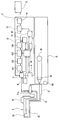
- FIG. 1 is a diagram showing an example of the entire configuration of an endoscope system including a touch panel device integrated with a video processor according to an embodiment of the present invention.
- the endoscope system includes an endoscope 2 that is inserted into a body cavity and observes or treats an affected part, and a video that performs predetermined signal processing on a video signal captured by the endoscope 2.
- a processor 1 is connected to an observation monitor 3 that displays an image subjected to signal processing.
- the observation monitor 3 is also used as an information display screen for confirming the setting contents of each part of the endoscope system.
- the video processor 1 is also provided with an electrostatic touch panel 4 for performing operation instructions on each part of the endoscope system and displaying the state of each part.
- FIG. 2 is a schematic block diagram illustrating a detailed configuration of the endoscope system.
- the endoscope 2 has an elongated insertion portion 25 that can be inserted into a body cavity of a patient, and an imaging element 24 such as a CCD is disposed at the distal end of the insertion portion 25.
- a connector portion 21 is provided on the proximal end side of the insertion portion 25 of the endoscope 2, and is detachably connected to the video processor 1 by an electric connector 21 a provided on the connector portion 21.
- the endoscope 2 is also provided with a light guide 23 that guides illumination light to the distal end of the insertion portion 25 and an operation switch 22 that operates each part of the endoscope 2.
- the insertion portion of the endoscope 2 may be flexible or rigid (a rigid endoscope used for surgery).
- the image pick-up element 24 is provided in the front-end
- the image sensor 24 is provided in an operation unit (portion held by the user) where the operation switch 22 is provided, and an optical image is captured by an image guide fiber from the distal end of the insertion unit 25 to the image sensor 24 in the operation unit. It may be configured to transmit.
- the light source device 6 includes a light source 61 such as a lamp that generates illumination light, a condensing lens 62 that condenses the illumination light emitted from the light source 61 on the incident end surface of the light guide 23, and various operations such as light amount adjustment. And an operation panel 63 for performing the above.
- a light source 61 such as a lamp that generates illumination light
- a condensing lens 62 that condenses the illumination light emitted from the light source 61 on the incident end surface of the light guide 23, and various operations such as light amount adjustment.
- an operation panel 63 for performing the above.
- an LED or a laser diode (semiconductor light source) may be used as the light source 61.
- a semiconductor light source that emits white light may be used, or a semiconductor light source is provided for each of R (red), G (green), and B (blue) color components, and these semiconductor light sources are used.
- the white light may be obtained by combining the light of each color component
- the light source device 6 is configured separately from the video processor 1.
- the video processor 1 and the light source device 6 are connected and used, it is necessary to determine their compatibility. This compatibility determination is performed according to the following procedure.
- both the video processor 1 and the light source device 6 grasp the model name of the other device connected to itself.
- Each of the video processor 1 and the light source device 6 compares a device name acquired from the other device with a compatibility table (table storing a list of device model names that can be combined with the device name). 2. Based on the above, it is determined whether or not the connected devices are devices that can be combined. 3. The video processor 1 and the light source device 6 output their own compatibility determination results to the other device. If at least one of the determination result of the device itself and the determination result of the other device is a determination result that is not compatible, the fact is notified to the user. For this notification, the video processor 1 and the light source device 6 are For example, blinking LEDs provided around various switches provided on the front panel of at least one of the light source device 6 and the video processor 1. You may inform by.
- the light source device 6 is configured separately from the video processor 1, but may be configured as a light source device integrated video processor provided inside the video processor.
- the video processor 1 includes a touch panel 4, a connector 11 connected to the electrical connector 21a of the endoscope 2, a video processing unit 12, an encoder 13, a display controller 14, a video signal switching circuit 15, a D / A.
- the conversion circuit 16, the memory 17, and the control unit 18 are mainly configured.
- the touch panel device of this embodiment includes the touch panel 4 and the control unit 18.
- the touch panel 4 as a display unit is, for example, a touch panel display in which a liquid crystal display and an electrostatic touch panel sensor arranged so as to overlap the liquid crystal display are integrated.
- the operation device is used by a user to instruct each part of the video processor 1, and operation information is input to the control unit 18.
- the touch panel 4 is also used as a display device for confirming the state of each part of the endoscope system such as the brightness of illumination light.
- touch panel display is not limited to the electrostatic type, but may be a pressure-sensitive type or other configuration, or may be configured to be removable from the video processor 1.
- the video processing unit 12 is a part that performs various processes on the video signal output from the image sensor 24 and generates a video to be displayed on the observation monitor 3.
- the video processing unit 121, the A / D conversion circuit 122, and white A balance circuit 123 and an image processing circuit 124 are included.
- the video processing circuit 121 performs predetermined processing such as AGC processing (auto gain control processing) and CDS processing (correlated double sampling processing) on the analog video signal output from the image sensor 24.
- the A / D conversion circuit 122 converts the analog video signal input from the video processing circuit 121 into a digital video signal.
- the white balance circuit 123 performs processing (white balance processing) for obtaining an image having a desired color tone by correcting the influence of the color of light in the shooting environment.
- the image processing circuit 124 performs predetermined processing such as color correction, distortion correction processing, and enhancement processing on the video signal after the white balance processing.
- the image processing circuit 124 converts the video signal into a signal format for displaying on the observation monitor 3.
- the encoder 13 takes in the digital video signal output from the video processing unit 12, encodes it in a predetermined recording format, and generates a video or a still image to be stored in the recording medium 5.
- the display controller 14 generates various screens (for example, a setting screen and an information display screen) to be displayed on the observation monitor 3.
- the video signal switching circuit 15 selects either the video signal output from the video processing unit 12 or the screen output from the display controller 14 as the display content of the observation monitor 3 in accordance with an instruction from the control unit 18. Switch the output signal.
- the D / A conversion circuit 16 converts the digital signal input from the video signal switching circuit 15 into an analog signal and outputs the analog signal to the observation monitor 3.
- the memory 17 stores parameters and setting values used in each part of the video processor 1.
- the memory 17 also stores settings related to the storage format (file management structure) of video and still images stored on the recording medium 5.
- the control unit 18 controls each part of the video processor 1 based on an instruction input from the user via the touch panel 4, parameters and setting values stored in the memory 17, and the like.
- the control unit 18 controls the entire display of the touch panel 4 such as a menu screen display on the touch panel 4 as a display control unit, and detects a touch panel operation and sets a lock state as a touch panel control unit. Further, when an instruction to save video or still images is input from the user, the control unit 18 outputs the video and still images to the recording medium 5 attached to the video processor 1.
- the video processor 1 is configured to be connected to the endoscope 2, but the present invention is not limited to this.
- the video processor 1 is an optical type inserted into a body cavity.
- a configuration may be adopted in which a camera head attached to an eyepiece of a endoscope (fiber scope or optical tube for surgery) is connected.
- the endoscope 2 and the video processor 1 are connected by the electrical connector 21a and the connector 11 and are configured to transmit electrical signals by wire, the present invention is not limited to this, and the electrical signals are transmitted wirelessly. It may be configured to transmit.
- FIG. 3 to 7 are diagrams for explaining various screens displayed on the touch panel 4.
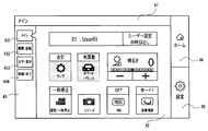
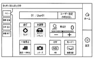
- FIG. 3 is a main menu screen
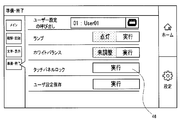
- FIG. 4 is a submenu screen
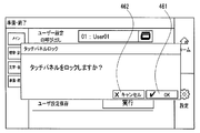
- FIG. 5 is a touch panel lock confirmation screen
- FIG. FIG. 7 shows an example of the touch panel unlock screen.
- a screen information area 41 On the menu screen displayed on the touch panel 4, for example, as shown in FIG. 3, a screen information area 41, a display / setting area 42, a menu screen selection area 43, a home button 44, and a setting button 45 are arranged. Has been.
- the screen information area 41 is an area corresponding to the title bar, and is an area in which information regarding the currently displayed screen is displayed. For example, when the main menu screen is displayed, as shown in FIG. 3, the character string “main” is displayed. For example, when a submenu screen related to preparation / end is displayed, a character string “preparation / end” is displayed as shown in FIG.
- the display / setting area 42 is an area for displaying information related to functions set in advance for each menu screen and for setting the functions.
- the display / setting area 42 includes user information, the brightness state of the endoscope image, the white balance adjustment state, the observation video recording state, and the observation image shooting mode.
- Information that is important for endoscopy, such as the presence or absence of special light observation, the display mode of the observation image, and information that is frequently referred to by the examiner are displayed.
- the brightness of the endoscopic image may be changed at any time with reference to the observation image, so a setting button is provided.
- the display / setting area 42 sets and stores user information, executes lighting lamps of the light source device, executes white balance adjustment, and locks the touch panel.
- Setting buttons related to functions that require preparation and settings prior to the endoscopic examination, such as execution, are arranged.
- the menu screen selection area 43 is an area where buttons for selecting a menu screen to be displayed in the display / setting area 42 are arranged. For example, as shown in FIG. 3, four buttons, a main button 431, an observation / record button 432, a character / display button 433, and a preparation / end button 434, are arranged. By pressing each button, a predetermined menu is displayed. A screen is displayed in the display / setting area 42. For example, when the main button 431 is pressed, the main menu screen shown in FIG. 3 is displayed, and when the preparation / end button 434 is pressed, a submenu screen related to preparation / end shown in FIG. 4 is displayed.
- the home button 44 is a button for displaying a screen set as a home screen. Normally, when the home button 44 is pressed, the main menu screen shown in FIG.
- the setting button 45 is a button for displaying a setting screen for setting a function that cannot be set on the main menu screen and the submenu screen and a detailed setting of each function.
- the configuration of the main menu screen and the sub menu screen described above is merely an example, and can be changed to any configuration in consideration of usability and the like.
- the submenu screen may be provided with a screen for setting a color and brightness in addition to three screens relating to “observation / recording”, “character / display”, and “preparation / end”.
- the information displayed on each menu screen and the functions that can be set from each menu screen are not limited to the above example.
- widgets arranged on the screen for selecting a menu screen or executing a predetermined function are not limited to the buttons as described above, and a radio button or combo is used for selecting a menu screen or function. Other widgets may be used, such as a box.
- FIG. 8 is a flowchart illustrating a series of procedures for touch panel lock and release.
- the main menu screen shown in FIG. 3 is displayed on the touch panel 4.
- a method of locking and releasing the touch operation on the touch panel 4 from this state will be described.
- the preparation / end button 434 on the main menu screen is pressed to call the “preparation / end” submenu screen shown in FIG.
- the touch panel lock execution button 46 on the “prepare / end” submenu screen is pressed (step S1).
- the touch operation is not immediately locked, but as shown in FIG. 5, the touch panel lock confirmation screen is displayed superimposed on the “preparation / end” submenu screen, and the final determination as to whether or not to lock is performed.
- An input of intention is requested (step S2).
- step S2 When the cancel button 462 on the touch panel lock confirmation screen is pressed (step S2, NO), the touch panel lock confirmation screen disappears and the display returns to the “preparation / end” submenu screen.
- the OK button 461 on the touch panel lock confirmation screen is pressed (step S2, YES)
- the touch operation on the touch panel is locked
- the touch panel lock confirmation screen disappears, and the display returns to the main menu screen.
- a character string such as “touch panel is locked” is displayed in the screen information area 41 so that the user can easily recognize that the touch operation is locked (step S3).
- a character string such as “touch panel locked” may be displayed in a semi-transparent manner at an arbitrary position on the screen so that the user can recognize that the touch operation is locked.
- the lock of the touch operation on the touch panel 4 is completed by the above series of procedures.
- the touch operation is locked, it is displayed in the display / setting area 42 by a method other than the touch operation such as an input operation of a switch or the like provided in a portion other than the touch panel of the video processor main body.
- a method other than the touch operation such as an input operation of a switch or the like provided in a portion other than the touch panel of the video processor main body.
- a touch panel unlock screen is displayed superimposed on the main menu screen (step S5, FIG. 7).
- An unlock button 463 is arranged on the touch panel unlock screen.
- the touch panel unlock screen displays a method for unlocking on the screen.
- the lock release button 463 is also labeled “unlock (long press for 5 seconds)”.
- the method of unlocking is not limited to the method of pressing and holding the unlock button for a long time.
- a plurality of unlock buttons are provided on the touch panel unlock screen and the buttons are pressed at the same time. The method can be used.
- the long press time required for releasing is not limited to 5 seconds, and it may be set shorter or longer. Good.
- step S7 since the touch panel 4 is unlocked and a touch operation is possible, a character string “main” is displayed in the screen information area 41 of the main menu screen.
- step S6 when the unlocking method is insufficiently executed on the touch panel unlock screen (for example, when the time to continuously press the unlock button 463 is less than 5 seconds), the touch panel lock is not released and the touch panel is unlocked.
- the unlock screen continues to be displayed (step S6, NO). Note that by pressing the cancel button 464 arranged on the touch panel unlock screen (step S8, YES), it is possible to return to the display of the main menu screen while the touch operation is locked.
- the main menu screen is displayed on the touch panel even when the touch operation of the touch panel 4 is locked.
- Indicators indicating function settings and states for example, observation mode settings and dimming level states
- the touch operation is locked at a predetermined position on the main menu screen such as the screen information area 41, the user can recognize at a glance whether the touch operation is valid or invalid. it can. Therefore, user convenience is improved.
- the touch panel unlock screen is displayed when the user touches the touch panel.
- the unlock method is shown on the screen, so even if the user does not know the specific method of unlocking, the user can easily lock the screen by looking at the notation on the touch panel unlock screen. You can know how to cancel.
- the user since the user can lock or unlock the touch operation on the touch panel without interrupting the endoscope operation, user convenience is further improved.
- each “unit” in this specification is a conceptual one corresponding to each function of the embodiment, and does not necessarily correspond to a specific hardware or software routine on a one-to-one basis. Therefore, in the present specification, the embodiment has been described assuming a virtual circuit block (unit) having each function of the embodiment.
- each step of each procedure in the present embodiment may be executed in a different order for each execution by changing the execution order and performing a plurality of steps at the same time, as long as it does not contradict its nature.
- all or part of each step of each procedure in the present embodiment may be realized by hardware.
- the touch panel device of the present invention it is possible to easily switch between valid / invalid operation detection of the touch panel, and confirm the display content of the menu screen even when the touch panel operation detection is invalid, User convenience is improved.
Landscapes
- Engineering & Computer Science (AREA)
- General Engineering & Computer Science (AREA)
- Theoretical Computer Science (AREA)
- Human Computer Interaction (AREA)
- Physics & Mathematics (AREA)
- General Physics & Mathematics (AREA)
- Endoscopes (AREA)
- Instruments For Viewing The Inside Of Hollow Bodies (AREA)
Abstract
タッチパネル装置は、タッチ操作を検出するタッチパネル4と、タッチ操作により操作する操作ボタンを含むメニュー画面をタッチパネル4に表示させたり、メニュー画面に設けられた所定のボタンの操作検出に応じて、タッチパネル4へのタッチ操作を無効とするロック状態とタッチ操作を有効とする非ロック状態とを設定したりする制御部18とを有する。制御部18は、ロック状態下でタッチ操作が未検出である場合にはメニュー画面を表示させ、ロック状態下でタッチ操作が検出された場合には、ロック状態を非ロック状態に移行させるための手順を表した解除画面を表示させる。
Description
本発明は、タッチパネル装置に関し、特に、タッチパネルへの意図しない接触による誤操作を防止する、タッチパネル装置に関するものである。
従来、内視鏡により撮像された被写体の観察画像などを生成するビデオプロセッサは、当該ビデオプロセッサに設けられたタッチパネルに表示されているメニュー画面を操作することにより、各種機能を設定したり実行したりする。
一般的に、ビデオプロセッサが動作している間はタッチパネルも電源オンの状態を維持する。しかし、電源オンの状態で、タッチパネルに付着した汚れを除去するために清掃を行った場合、意図せずにメニュー画面上に配置されたボタンを押下してしまい、ビデオプロセッサを誤動作させてしまうことが問題となっていた。
そこで、電源をオンの状態に保ったまま、タッチパネルの操作検出をロックすることができるタッチパネル装置が提案されている(例えば、日本国特開2013-42427号公報参照)。
しかしながら、日本国特開2013-42427号公報に記載されたタッチパネル装置は、タッチ操作の検出をロックするロック状態に設定すると、設定前に表示されていたメニュー画面を参照することができない。このため、メニュー画面に表示されている各種機能の設定や状態を示すインジケータ(例えば、観察モードの設定や、調光レベルの状態など)を参照することができず、ユーザがこれらの情報を参照したい場合は、都度、ロック状態を解除する必要があり、操作が煩わしくなってしまうという問題があった。
そこで、本発明は、タッチパネルの操作検出の有効・無効の切り替えを簡単に実行可能にするとともに、タッチパネル操作検出無効時であってもメニュー画面の表示内容を確認可能とすることで、ユーザの利便性が向上するタッチパネル装置を提供することを目的とする。
本発明の一態様のタッチパネル装置は、ユーザによるタッチ操作を検出するタッチパネルを備えた表示部と、前記表示部に前記タッチ操作により操作されるための操作ボタンを含むメニュー画面を表示させるための表示制御部と、前記メニュー画面に設けられた所定のボタンの操作検出に応じて、前記タッチパネルへの前記タッチ操作を無効とするロック状態と前記タッチ操作を有効とする非ロック状態とを設定可能なタッチパネル制御部と、を備えている。前記表示制御部は、前記ロック状態下で前記タッチ操作が未検出である場合には前記メニュー画面の表示を維持させ、前記ロック状態下で前記タッチ操作が検出された場合に前記ロック状態を前記非ロック状態に移行させるための手順を表した解除画面を表示させる。
以下、図面を参照して実施形態を説明する。
図1は、本発明の実施形態に係るビデオプロセッサ一体型のタッチパネル装置を含む内視鏡システムの全体構成の一例を示す図である。内視鏡システムは、例えば、図1に示すように、体腔内に挿入し患部を観察あるいは処置する内視鏡2と、内視鏡2により撮像された映像信号に所定の信号処理を施すビデオプロセッサ1とを有して構成されている。ビデオプロセッサ1には、信号処理が施された映像を表示する観察モニタ3が接続されている。なお、観察モニタ3は、内視鏡システムの各部の設定内容を確認するための情報表示画面としても用いられる。また、ビデオプロセッサ1には、内視鏡システムの各部位に対して操作指示を行ったり各部位の状態を表示したりするための静電式のタッチパネル4も設けられている。
図2は、内視鏡システムの詳細な構成を説明する概略ブロック図である。図2に示すように、内視鏡2は、患者の体腔内等に挿入可能な細長の挿入部25を有しており、挿入部25の先端には例えばCCD等の撮像素子24が配設されている。内視鏡2の挿入部25の基端側はコネクタ部21が設けられており、コネクタ部21に設けられた電気コネクタ21aによって、着脱自在にビデオプロセッサ1に接続されるようになっている。また、内視鏡2には、挿入部25の先端へ照明光を導くライトガイド23と、内視鏡2の各部の操作を行う操作スイッチ22とも設けられている。
なお、内視鏡2の挿入部は、軟性であってもよいし、硬性(外科手術に用いられる硬性内視鏡)であってもよい。また、撮像素子24は、内視鏡2の挿入部25の先端に設けられているが、これに限定されるものではない。例えば、撮像素子24は、操作スイッチ22が設けられている操作部(ユーザにより把持される部分)内に設けられ、挿入部25の先端から操作部内の撮像素子24までイメージガイドファイバで光学像を伝送する構成であってもよい。
光源装置6は、照明光を生成する例えばランプ等の光源61と、光源61から照射される照明光をライトガイド23の入射端面に集光させる集光レンズ62と、光量の調整等の各種操作を行うための操作パネル63とを有する。なお、光源61としては、ランプの他に、例えばLEDやレーザーダイオード(半導体光源)を用いてもよい。また、半導体光源を用いる場合、白色光を出射する半導体光源を用いてもよいし、R(赤)、G(緑)、B(青)の色成分毎に半導体光源を設け、これらの半導体光源から出射される各色成分の光を合波して白色光を得るものであってもよい。
尚、図1において光源装置6はビデオプロセッサ1と別体で構成されており、ビデオプロセッサ1と光源装置6とを接続して使用するに当たって、これらの互換性を判別する必要がある。この互換性判別は以下の手順で行われる。
1.ビデオプロセッサ1と光源装置6との間の通信によって、ビデオプロセッサ1と光源装置6の双方が自身に接続された他方の機器の機種名を把握する。
2.ビデオプロセッサ1と光源装置6とは、それぞれ、他方の装置から取得した機器名称と自身が保持している互換性テーブル(自身が組み合わせ可能な機器の機種名一覧を記憶したテーブル)との比較結果に基づいて、接続された機器が組み合わせ可能な機器であるか否かを判定する
3.ビデオプロセッサ1と光源装置6とは、自身での互換性判定結果を他方の機器へ出力する
4.自身の判定結果と他方の機器の判定結果の少なくともいずれか一方が互換性なしとの判定結果である場合、ユーザにその旨を報知する
この報知としては、モニタにビデオプロセッサ1と光源装置6との互換性がない旨の表示を行うものであっても良いし、例えば光源装置6、ビデオプロセッサ1のうち少なくとも一方のフロントパネルに設けられている各種スイッチ周辺に設けられたLEDを点滅させることで報知しても良い。
3.ビデオプロセッサ1と光源装置6とは、自身での互換性判定結果を他方の機器へ出力する
4.自身の判定結果と他方の機器の判定結果の少なくともいずれか一方が互換性なしとの判定結果である場合、ユーザにその旨を報知する
この報知としては、モニタにビデオプロセッサ1と光源装置6との互換性がない旨の表示を行うものであっても良いし、例えば光源装置6、ビデオプロセッサ1のうち少なくとも一方のフロントパネルに設けられている各種スイッチ周辺に設けられたLEDを点滅させることで報知しても良い。
尚、図1において光源装置6はビデオプロセッサ1と別体で構成されているが、ビデオプロセッサ内部に設けられた光源装置一体型ビデオプロセッサとして構成されていてもよい。
ビデオプロセッサ1は、タッチパネル4と、内視鏡2の電気コネクタ21aと接続されるコネクタ11と、映像処理部12と、エンコーダ13と、表示コントローラ14と、映像信号切替回路15と、D/A変換回路16と、メモリ17と、制御部18とから主に構成されている。本実施形態のタッチパネル装置は、タッチパネル4と制御部18とから構成される。
表示部としてのタッチパネル4は、例えば、液晶ディスプレイと、液晶ディスプレイに重ねて配置された静電型のタッチパネルセンサとが一体となって構成された、タッチパネルディスプレイである。ユーザがビデオプロセッサ1の各部位に指示するための操作装置であり、操作情報は制御部18に入力される。また、タッチパネル4は、照明光の明るさなど内視鏡システムの各部位の状態を確認するための表示装置としても用いられる。
尚、このタッチパネルディスプレイは、静電型に限定されるものでなく、感圧型やその他の構成を用いたものであってもよいし、ビデオプロセッサ1から取り外し可能に構成されていてもよい。
映像処理部12は、撮像素子24から出力される映像信号に各種の処理を施して、観察モニタ3に表示させる映像を生成する部位であり、映像処理回路121、A/D変換回路122、ホワイトバランス回路123、画像処理回路124を有して構成される。
映像処理回路121は、撮像素子24から出力されるアナログの映像信号に対して、AGC処理(オートゲインコントロール処理)やCDS処理(相関二重サンプリング処理)など所定の処理を施す。A/D変換回路122は、映像処理回路121から入力されるアナログの映像信号をデジタルの映像信号に変換する。ホワイトバランス回路123は、撮影環境での光の色の影響を補正して、望んだ色調の映像を得るための処理(ホワイトバランス処理)を行う。画像処理回路124は、ホワイトバランス処理後の映像信号に対し、色補正や歪み補正処理や強調処理など、所定の処理を施す。また、画像処理回路124は、映像信号を観察モニタ3に表示するための信号形式に変換する。
エンコーダ13は、映像処理部12から出力されるデジタルの映像信号を取り込んで所定の記録形式で符号化し、記録メディア5に保存するための映像や静止画像を生成する。表示コントローラ14は、観察モニタ3に表示させるための各種画面(例えば、設定画面や情報表示画面など)を生成する。映像信号切替回路15は、制御部18からの指示に従い、観察モニタ3の表示内容として、映像処理部12から出力される映像信号と、表示コントローラ14から出力される画面のいずれかを選択し、出力信号の切り替えを行う。D/A変換回路16は、映像信号切替回路15から入力されるデジタルの信号をアナログの信号に変換し、観察モニタ3に出力する。
メモリ17は、ビデオプロセッサ1の各部位で用いられるパラメータや設定値などを保存している。なお、メモリ17には、記録メディア5で保存する映像や静止画像の保存形式(ファイルの管理構造)に関する設定も保存されている。
制御部18は、タッチパネル4を介してユーザから入力される指示や、メモリ17に保存されているパラメータや設定値などに基づき、ビデオプロセッサ1の各部位を制御する。また、制御部18は、表示制御部として、タッチパネル4へのメニュー画面表示などタッチパネル4の表示全体の制御を行ったり、タッチパネル制御部として、タッチパネル操作の検出やロック状態の設定を行ったりする。更に、制御部18は、ユーザから映像や静止画像の保存指示が入力されると、ビデオプロセッサ1に装着された記録メディア5に、同映像及び静止画像を出力する。
なお、図2を用いた上記の説明において、ビデオプロセッサ1は内視鏡2が接続される構成になっているが、これに限定されるものではなく、例えば体腔内に挿入される光学式内視鏡(ファイバースコープ、あるいは外科手術用の光学視管)の接眼部に装着されるカメラヘッドが接続される構成であってもよい。
更に、内視鏡2及びビデオプロセッサ1は、電気コネクタ21a及びコネクタ11により接続され、電気信号を有線で伝送する構成になっているが、これに限定されるものではなく、電気信号を無線で伝送する構成であってもよい。
次に、タッチパネル4に表示されるメニュー画面について説明する。図3から図7は、タッチパネル4に表示される各種画面を説明する図であり、図3はメインメニュー画面、図4はサブメニュー画面、図5はタッチパネルロック確認画面、図6はタッチパネルロック中の画面、図7はタッチパネルロック解除画面の一例を示している。
タッチパネル4に表示されるメニュー画面には、例えば図3に示すように、画面情報エリア41と、表示・設定エリア42と、メニュー画面選択エリア43と、ホームボタン44と、設定ボタン45とが配置されている。
画面情報エリア41は、タイトルバーに相当するエリアであり、現在表示されている画面に関する情報が表示される領域である。例えば、メインメニュー画面が表示されている場合、図3に示すように、「メイン」の文字列が表示される。また例えば、準備・終了に関するサブメニュー画面が表示されている場合、図4に示すように、「準備・終了」の文字列が表示される。
表示・設定エリア42は、メニュー画面ごとに予め設定された機能に関する情報を表示したり、該機能の設定を行ったりする領域である。例えば、図3に示すメインメニュー画面の場合、表示・設定エリア42には、ユーザ情報、内視鏡画像の明るさの状態、ホワイトバランスの調整状態、観察映像の記録状態、観察画像の撮影モード、特殊光観察の有無、観察画像の表示モードなど、内視鏡検査にあたり重要な情報や、検査者が参照する頻度の高い情報が表示される。また、内視鏡画像の明るさについては、観察画像を参照しながら随時変更する可能性があるので、設定ボタンが設けられている。
また例えば、図4に示す準備・終了に関するサブメニュー画面の場合、表示・設定エリア42には、ユーザ情報の設定及び保存、光源装置の照明ランプの点灯実行、ホワイトバランスの調整実行、タッチパネルのロック実行、など、内視鏡検査に先立って準備や設定が必要な機能に関する設定ボタンが配置されている。
メニュー画面選択エリア43は、表示・設定エリア42に表示させるメニュー画面を選択するボタンが配置されている領域である。例えば図3に示すように、メインボタン431、観察・記録ボタン432、文字・表示ボタン433、準備・終了ボタン434の4つのボタンが配置されており、各ボタンを押下することで、所定のメニュー画面が表示・設定エリア42に表示される。例えば、メインボタン431を押下すると、図3に示すメインメニュー画面が表示され、準備・終了ボタン434を押下すると、図4に示す準備・終了に関するサブメニュー画面が表示される。
ホームボタン44は、ホーム画面として設定された画面を表示させるためのボタンである。通常、ホームボタン44を押下すると、図3に示すメインメニュー画面がタッチパネル4に表示される。
設定ボタン45は、メインメニュー画面及びサブメニュー画面で設定することができない機能の設定や、各機能の詳細な設定を行うための設定画面を表示させるためのボタンである。
なお、上述したメインメニュー画面やサブメニュー画面の構成は一例にすぎず、ユーザビリティ等を勘案して任意の構成に変更可能である。例えば、サブメニュー画面は「観察・記録」「文字・表示」「準備・終了」に関する3つの画面に加え、色や明るさを設定するための画面などを設けてもよい。また、各メニュー画面に表示させる情報や、各メニュー画面から設定可能な機能も、上述の例に限定されない。更に、メニュー画面を選択したり、所定の機能を実行したりするために画面上に配置されるウィジェットも、上述のようなボタンに限定されず、メニュー画面や機能の選択にはラジオボタンやコンボボックスを用いるなど、他のウィジェットを用いてもよい。
次に、タッチパネル4におけるタッチ操作をロック及び解除する手順について説明する。図8は、タッチパネルロック及び解除の一連の手順を説明するフローチャートである。通常、タッチパネル4には、図3に示すメインメニュー画面が表示されている。この状態から、タッチパネル4のタッチ操作をロックし解除する方法について説明する。
まず、メインメニュー画面の準備・終了ボタン434を押下し、図4に示す「準備・終了」サブメニュー画面を呼び出す。そして、「準備・終了」サブメニュー画面のタッチパネルロック実行ボタン46を押下する(ステップS1)。すると、すぐにタッチ操作がロックされるのではなく、図5に示すように、「準備・終了」サブメニュー画面に重畳してタッチパネルロック確認画面が表示され、ロックするか否かの最終的な意思の入力が要求される(ステップS2)。
タッチパネルロック確認画面のキャンセルボタン462を押下すると(ステップS2、NO)、タッチパネルロック確認画面が消えて、「準備・終了」サブメニュー画面の表示に戻る。一方、タッチパネルロック確認画面のOKボタン461を押下すると(ステップS2、YES)、タッチパネルに対するタッチ操作がロックされ、タッチパネルロック確認画面が消えてメインメニュー画面の表示に戻る。このとき、タッチ操作がロックされていることをユーザが容易に認識できるように、画面情報エリア41に「タッチパネルロック中」などの文字列が表示される(ステップS3)。 また、タッチ操作がロックされていることをユーザが認識できるよう、画面上の任意の箇所に「タッチパネルロック中」などの文字列を半透明で表示させてもよい。以上の一連の手順により、タッチパネル4におけるタッチ操作のロックを完了する。
尚、タッチ操作がロックされている場合であっても、例えばビデオプロセッサ本体のタッチパネル以外の部分に設けられたスイッチ等の入力操作などタッチ操作以外の方法で表示・設定エリア42に表示されている情報やパラメータが変化した場合、画面上の情報やパラメータにも変化が反映される。
続いて、タッチ操作のロック解除の手順について説明する。タッチ操作ロック中に、タッチパネル4に表示されているメインメニュー画面の任意の場所を押下すると(ステップS4、YES)、メインメニュー画面に重畳してタッチパネルロック解除画面が表示される(ステップS5、図7参照)。タッチパネルロック解除画面には、ロック解除ボタン463が配置されている。また、タッチパネルロック解除画面には、ロックを解除する方法が画面上に示される。
例えば、図7に示す一例では、ロックを解除する方法として、「タッチパネルロックを解除するには、ロック解除ボタンを5秒以上押してください」の表記がなされている。また、ロック解除ボタン463にも、「ロック解除(5秒長押し)」の表記がなされている。なお、ロック解除の方法は、ロック解除ボタンを長押しする方法に限定されるものではなく、例えば、タッチパネルロック解除画面にロック解除ボタンを複数設け、これらのボタンを同時に押下する方法など、任意の方法を用いることができる。また、ロック解除ボタンを長押しすることよりロック解除を行う場合にも、解除までに必要な長押し時間は5秒に限定されるものではなく、これより短く設定しても長く設定してもよい。
ユーザは、タッチパネルロックを解除したい場合、画面上に記載されたロック解除の方法を実行する。図7に示す一例の場合、ロック解除ボタン463を5秒以上長押しする(ステップS6、YES)。すると、タッチパネルロックが解除され、図3に示すメインメニュー画面が表示される(ステップS7)。なお、ステップS7では、タッチパネル4のロックが解除されてタッチ操作が可能な状態となっているので、メインメニュー画面の画面情報エリア41には「メイン」の文字列が表示されている。
一方、タッチパネルロック解除画面において、ロック解除の方法の実行が不十分だった場合(例えば、ロック解除ボタン463を連続して押下する時間が5秒未満の場合)、タッチパネルロックは解除されず、タッチパネルロック解除画面が継続して表示される(ステップS6、NO)。なお、タッチパネルロック解除画面に配置されたキャンセルボタン464を押下することで(ステップS8、YES)、タッチ操作をロックした状態のままメインメニュー画面の表示に戻ることができる。
以上に述べたように、本実施形態によれば、タッチパネル4のタッチ操作をロックした状態においても、タッチパネル上にメインメニュー画面が表示されるので、ユーザは、同画面の表示内容(例えば、各種機能の設定や状態を示すインジケータ(例えば、観察モードの設定や、調光レベルの状態など))を参照することができる。また、画面情報エリア41などメインメニュー画面の所定位置に、タッチ操作がロックされていることが表示されているため、ユーザはタッチ操作が有効であるか無効であるかを一目で認識することができる。従って、ユーザの利便性が向上する。
更に、タッチ操作がロックされている状態において、ユーザがタッチパネルに触れることにより、タッチパネルロック解除画面が表示される。タッチパネルロック解除画面には、ロックを解除する方法が画面上に示されているので、ユーザはロック解除の具体的な方法を知らなくても、タッチパネルロック解除画面の表記を見れば、容易にロック解除の方法を知ることができる。このように、ユーザは内視鏡操作を中断することなく、タッチパネルのタッチ操作をロックしたり、ロック解除を行ったりすることができるため、ユーザの利便性が更に向上する。
本明細書における各「部」は、実施の形態の各機能に対応する概念的なもので、必ずしも特定のハードウェアやソフトウエア・ルーチンに1対1には対応しない。従って、本明細書では、実施の形態の各機能を有する仮想的回路ブロック(部)を想定して実施の形態を説明した。また、本実施の形態における各手順の各ステップは、その性質に反しない限り、実行順序を変更し、複数同時に実行し、あるいは実行毎に異なった順序で実行してもよい。さらに、本実施の形態における各手順の各ステップの全てあるいは一部をハードウェアにより実現してもよい。
本発明のいくつかの実施形態を説明したが、これらの実施形態は、例として例示したものであり、発明の範囲を限定することは意図していない。これら新規な実施形態は、その他の様々な形態で実施されることが可能であり、発明の要旨を逸脱しない範囲で、種々の省略、置き換え、変更を行うことができる。これら実施形態やその変形は、発明の範囲や要旨に含まれると共に、特許請求の範囲に記載された発明とその均等の範囲に含まれる。
本発明のタッチパネル装置によれば、タッチパネルの操作検出の有効・無効の切り替えを簡単に実行可能にするとともに、タッチパネル操作検出無効時であってもメニュー画面の表示内容を確認可能とすることで、ユーザの利便性が向上する。
本出願は、2015年8月26日に日本国に出願された特願2015-167081号を優先権主張の基礎として出願するものであり、上記の開示内容は、本願明細書、請求の範囲に引用されるものとする。
Claims (6)
- ユーザによるタッチ操作を検出するタッチパネルを備えた表示部と、
前記表示部に前記タッチ操作により操作されるための操作ボタンを含むメニュー画面を表示させるための表示制御部と、
前記メニュー画面に設けられた所定のボタンの操作検出に応じて、前記タッチパネルへの前記タッチ操作を無効とするロック状態と前記タッチ操作を有効とする非ロック状態とを設定可能なタッチパネル制御部と、を備え、
前記表示制御部は、前記ロック状態下で前記タッチ操作が未検出である場合には前記メニュー画面の表示を維持させ、前記ロック状態下で前記タッチ操作が検出された場合に前記ロック状態を前記非ロック状態に移行させるための手順を表した解除画面を表示させることを特徴とする、タッチパネル装置。 - 前記表示制御部は、前記ロック状態であるときに、前記タッチパネル制御部によって前記ロック状態に設定されている旨のメッセージを表示させることを特徴とする、請求項1に記載のタッチパネル装置。
- 前記表示制御部は、前記解除画面として前記ロック状態を解除するための解除ボタンを表示するものであり、前記タッチパネル制御部は、前記解除ボタンに対する所定の操作の検出を以て、前記ロック状態から前記非ロック状態へ設定を変更することを特徴とする、請求項1に記載のタッチパネル装置。
- 前記所定の操作は、前記解除ボタンに対する所定時間以上の長押し操作であることを特徴とする、請求項3に記載のタッチパネル装置。
- 前記表示制御部は、前記ロック状態において、前記メニュー画面に表示している情報又はパラメータに変化が生じた場合、前記メニュー画面に前記変化を反映させる、ことを特徴とする請求項1に記載のタッチパネル装置。
- 前記タッチパネル装置は、内視鏡システムのビデオプロセッサ用の前記タッチパネル装置であることを特徴とする、請求項1に記載のタッチパネル装置。
Applications Claiming Priority (2)
| Application Number | Priority Date | Filing Date | Title |
|---|---|---|---|
| JP2015167081 | 2015-08-26 | ||
| JP2015-167081 | 2015-08-26 |
Publications (1)
| Publication Number | Publication Date |
|---|---|
| WO2017033488A1 true WO2017033488A1 (ja) | 2017-03-02 |
Family
ID=58099801
Family Applications (1)
| Application Number | Title | Priority Date | Filing Date |
|---|---|---|---|
| PCT/JP2016/060423 Ceased WO2017033488A1 (ja) | 2015-08-26 | 2016-03-30 | タッチパネル装置 |
Country Status (1)
| Country | Link |
|---|---|
| WO (1) | WO2017033488A1 (ja) |
Cited By (1)
| Publication number | Priority date | Publication date | Assignee | Title |
|---|---|---|---|---|
| JP2019141260A (ja) * | 2018-02-19 | 2019-08-29 | 株式会社吉田製作所 | 情報表示システム、情報表示装置、情報表示方法および情報表示プログラム |
Citations (4)
| Publication number | Priority date | Publication date | Assignee | Title |
|---|---|---|---|---|
| JPH11318805A (ja) * | 1998-05-12 | 1999-11-24 | Olympus Optical Co Ltd | 内視鏡システム |
| JP2009198523A (ja) * | 2006-06-05 | 2009-09-03 | Mitsubishi Electric Corp | 表示装置および同装置における操作設定方法 |
| US20100020035A1 (en) * | 2008-07-23 | 2010-01-28 | Hye-Jin Ryu | Mobile terminal and event control method thereof |
| JP2012048283A (ja) * | 2010-08-24 | 2012-03-08 | Kyocera Corp | 携帯端末、ロック解除プログラムおよびロック解除方法 |
-
2016
- 2016-03-30 WO PCT/JP2016/060423 patent/WO2017033488A1/ja not_active Ceased
Patent Citations (4)
| Publication number | Priority date | Publication date | Assignee | Title |
|---|---|---|---|---|
| JPH11318805A (ja) * | 1998-05-12 | 1999-11-24 | Olympus Optical Co Ltd | 内視鏡システム |
| JP2009198523A (ja) * | 2006-06-05 | 2009-09-03 | Mitsubishi Electric Corp | 表示装置および同装置における操作設定方法 |
| US20100020035A1 (en) * | 2008-07-23 | 2010-01-28 | Hye-Jin Ryu | Mobile terminal and event control method thereof |
| JP2012048283A (ja) * | 2010-08-24 | 2012-03-08 | Kyocera Corp | 携帯端末、ロック解除プログラムおよびロック解除方法 |
Cited By (2)
| Publication number | Priority date | Publication date | Assignee | Title |
|---|---|---|---|---|
| JP2019141260A (ja) * | 2018-02-19 | 2019-08-29 | 株式会社吉田製作所 | 情報表示システム、情報表示装置、情報表示方法および情報表示プログラム |
| JP7121968B2 (ja) | 2018-02-19 | 2022-08-19 | 株式会社吉田製作所 | 情報表示システム、情報表示装置、情報表示方法および情報表示プログラム |
Similar Documents
| Publication | Publication Date | Title |
|---|---|---|
| WO2018207537A1 (ja) | ワイヤレス内視鏡及びワイヤレス内視鏡システム | |
| JP5173120B2 (ja) | 内視鏡装置 | |
| JP6214825B2 (ja) | 内視鏡プロセッサ | |
| WO2016017704A1 (ja) | 制御装置および内視鏡システム | |
| JP5751869B2 (ja) | 電子内視鏡装置、電子内視鏡用プロセッサ及び電子内視鏡システム | |
| JP2017045268A (ja) | タッチパネル装置 | |
| JP6743167B2 (ja) | 内視鏡スコープ、内視鏡プロセッサおよび内視鏡用アダプタ | |
| JP2016192986A (ja) | 内視鏡システム、及び、内視鏡システムの作動方法 | |
| JP5446413B2 (ja) | カメラ | |
| JP5231841B2 (ja) | 電子内視鏡装置 | |
| JP6254506B2 (ja) | 内視鏡システム及びその作動方法 | |
| WO2017033488A1 (ja) | タッチパネル装置 | |
| JPWO2017061284A1 (ja) | 撮像システム | |
| US12035878B2 (en) | Endoscope system for assiging multiple functions to a switch, control method of endoscope system and storage medium | |
| WO2017047321A1 (ja) | 信号処理装置 | |
| JP2011152302A (ja) | 電子内視鏡システム | |
| JP2011152300A (ja) | 電子内視鏡システム | |
| JP2013153991A (ja) | 電子内視鏡システム | |
| JP2013013589A (ja) | 画像信号処理装置、撮像システム、及び電子内視鏡システム | |
| JP2011152301A (ja) | 電子内視鏡システム | |
| JP6258834B2 (ja) | 内視鏡システム及びその作動方法 | |
| JP2016120026A (ja) | 内視鏡システム及びその作動方法 | |
| JP2017042417A (ja) | 内視鏡システム | |
| US11533419B2 (en) | Imaging apparatus, image sensor unit, camera unit, and control method for determining and updating correction data | |
| JP2014094140A (ja) | 内視鏡装置 |
Legal Events
| Date | Code | Title | Description |
|---|---|---|---|
| 121 | Ep: the epo has been informed by wipo that ep was designated in this application |
Ref document number: 16838835 Country of ref document: EP Kind code of ref document: A1 |
|
| NENP | Non-entry into the national phase |
Ref country code: DE |
|
| 122 | Ep: pct application non-entry in european phase |
Ref document number: 16838835 Country of ref document: EP Kind code of ref document: A1 |
|
| NENP | Non-entry into the national phase |
Ref country code: JP |