WO2017033372A1 - 自動車運搬船 - Google Patents
自動車運搬船 Download PDFInfo
- Publication number
- WO2017033372A1 WO2017033372A1 PCT/JP2016/003016 JP2016003016W WO2017033372A1 WO 2017033372 A1 WO2017033372 A1 WO 2017033372A1 JP 2016003016 W JP2016003016 W JP 2016003016W WO 2017033372 A1 WO2017033372 A1 WO 2017033372A1
- Authority
- WO
- WIPO (PCT)
- Prior art keywords
- deck
- boarding
- vehicle
- pillar
- entrance
- Prior art date
- Legal status (The legal status is an assumption and is not a legal conclusion. Google has not performed a legal analysis and makes no representation as to the accuracy of the status listed.)
- Ceased
Links
Images


Classifications
-
- B—PERFORMING OPERATIONS; TRANSPORTING
- B63—SHIPS OR OTHER WATERBORNE VESSELS; RELATED EQUIPMENT
- B63B—SHIPS OR OTHER WATERBORNE VESSELS; EQUIPMENT FOR SHIPPING
- B63B25/00—Load-accommodating arrangements, e.g. stowing, trimming; Vessels characterised thereby
- B63B25/002—Load-accommodating arrangements, e.g. stowing, trimming; Vessels characterised thereby for goods other than bulk goods
- B63B25/008—Load-accommodating arrangements, e.g. stowing, trimming; Vessels characterised thereby for goods other than bulk goods for wheeled cargo
-
- B—PERFORMING OPERATIONS; TRANSPORTING
- B63—SHIPS OR OTHER WATERBORNE VESSELS; RELATED EQUIPMENT
- B63B—SHIPS OR OTHER WATERBORNE VESSELS; EQUIPMENT FOR SHIPPING
- B63B3/00—Hulls characterised by their structure or component parts
- B63B3/14—Hull parts
- B63B3/48—Decks
- B63B3/52—Pillars; Deck girders
-
- B—PERFORMING OPERATIONS; TRANSPORTING
- B63—SHIPS OR OTHER WATERBORNE VESSELS; RELATED EQUIPMENT
- B63B—SHIPS OR OTHER WATERBORNE VESSELS; EQUIPMENT FOR SHIPPING
- B63B25/00—Load-accommodating arrangements, e.g. stowing, trimming; Vessels characterised thereby
-
- B—PERFORMING OPERATIONS; TRANSPORTING
- B63—SHIPS OR OTHER WATERBORNE VESSELS; RELATED EQUIPMENT
- B63B—SHIPS OR OTHER WATERBORNE VESSELS; EQUIPMENT FOR SHIPPING
- B63B25/00—Load-accommodating arrangements, e.g. stowing, trimming; Vessels characterised thereby
- B63B25/02—Load-accommodating arrangements, e.g. stowing, trimming; Vessels characterised thereby for bulk goods
- B63B25/04—Load-accommodating arrangements, e.g. stowing, trimming; Vessels characterised thereby for bulk goods solid
Definitions
- the present invention relates to a car carrier.
- an automobile carrier ship that transports a large number of vehicles is known (for example, see Patent Document 1).
- a plurality of intermediate decks are arranged between the upper deck and the double bottom, and a vehicle is mounted on these intermediate decks. Pillars lined up and down are interposed between the double bottom, the middle deck and the upper deck, and the load of each upper deck is supported by the lower structure through the pillars.
- the pillars are regularly arranged on the boarding deck which becomes the floor of the vehicle entrance. For this reason, when a vehicle is loaded and unloaded, a specific pillar may become an obstacle in vehicle traffic.
- an object of the present invention is to provide an automobile carrier ship that can improve the cargo handling efficiency during loading and unloading of vehicles.
- an automobile carrier of the present invention includes a hull including an upper deck and a double bottom, and a boarding deck and a boarding gate that are separated from each other across the vehicle boarding board.
- a plurality of intermediate decks including a direct upper deck, and a pillar arranged vertically between the double bottom, the plurality of intermediate decks and the upper deck, and in a specific pillar street cross section, the boarding deck A pillar is not provided between the deck directly above the entrance and exit, and the deck directly above the entrance and exit is suspended from the deck transformer that supports the upper deck via the pillar, It is characterized by having a rigidity that keeps the deflection of the upper deck just above the entrance / exit when the vehicle is fully installed on the entrance / exit deck.
- the vehicle can be fully mounted on the deck just above the entrance / exit without changing the deck just above the entrance / exit. Therefore, cargo handling efficiency at the time of loading and unloading of the vehicle can be improved.
- the deck transformer may be disposed on the upper deck. According to this configuration, since the relatively large deck transformer is not arranged in the hull, the above-described effect can be obtained without hindering the traffic of the vehicle on the uppermost intermediate deck.
- the deck transformer is a partition wall disposed between an intermediate deck located at an uppermost position among the plurality of intermediate decks and the upper deck, and a vehicle passage opening may be formed in the partition wall. Good. According to this configuration, although the traffic of the vehicle on the uppermost intermediate deck is slightly hindered, the above effect can be obtained without affecting the appearance of the car carrier and the limit of the depth of the ship. it can.
- the specific pillar street cross section may be a pillar street cross section closest to the vehicle entrance / exit. According to this configuration, it is possible to improve the vehicle trafficability in the vicinity of the vehicle entrance / exit.
- cargo handling efficiency at the time of loading and unloading of a vehicle can be improved.
- FIG. 1A and 1B are a side view and a plan view, respectively, of an automobile carrier according to a first embodiment of the present invention.
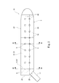
- 2 is a plan sectional view taken along line II-II in FIG. 1A.
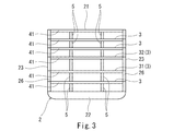
- FIG. 3 is a transverse sectional view taken along line III-III in FIG. 2.
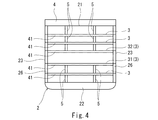
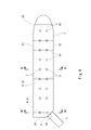
- FIG. 4 is a transverse sectional view taken along line IV-IV in FIG. 2. It is a cross-sectional view of the automobile carrier ship of a modification. It is a plane sectional view of a car carrier concerning a 2nd embodiment of the present invention.
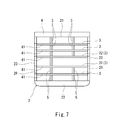
- FIG. 7 is a transverse sectional view taken along line VII-VII in FIG. 6.
- (First embodiment) 1A and 1B show an automobile carrier 1A according to a first embodiment of the present invention.
- This automobile carrier 1A includes a hull 2 in which a vehicle entrance 25 is formed.
- the hull 2 is provided with a foldable stern lamp 11 that enables loading and unloading of vehicles through the vehicle entrance 25.
- the hull 2 includes an upper deck 21, a double bottom 22, a pair of ship-side skins 23 and a stern skin 24.
- the vehicle entrance 25 described above is located between one ship side skin 23 and the stern skin 24.
- a plurality of intermediate decks 3 are provided in the hull 2.
- One of the intermediate decks 3 is a boarding deck 31 that becomes a floor surface of the vehicle entrance 25, and the intermediate deck 3 directly above the boarding deck 31 is a deck 32 directly above the boarding gate. That is, the boarding deck 31 and the deck 32 directly above the boarding / exiting opening are separated from each other with the vehicle boarding / unloading opening 25 interposed therebetween.
- each of the upper deck 21 and the intermediate deck 3 is supported by a number of deck transformers 41 extending in the ship width direction and two deck girders 42 extending in the ship length direction.
- the number of deck girders 42 may be one or three or more.
- each ship side outer plate 23 As shown in FIG. 3, to each ship side outer plate 23, a web frame 26 extending in a vertical direction from the double bottom 22 to the upper deck 21 is fixed. Both end portions of each deck transformer 41 are connected to the web frame 26.
- the pillar 5 is arranged at the intersection of the deck transformer 41 and the deck girder 42. As shown in FIG. 3, the pillar 5 is disposed between the double bottom 22 and the lowermost intermediate deck 3, between the intermediate decks 3, and between the uppermost intermediate deck 3 and the upper deck 21. Intervene.
- the upper part of each pillar 5 is connected to the deck transformer 41. However, the upper part of each pillar 5 may be connected to both the deck transformer 41 and the deck girder 42.
- Pillar 5 is lined up and down.
- the pillars 5 are arranged in two rows in all the pillar-passing cross sections (cross sections passing through the center of the pillar 5 in the ship width direction).
- the pillars 5 may be arranged in a line in all the pillar cross sections.
- a partition plate is provided in the double bottom 22 in the cross section through the pillar.
- the pillars 5 are located at all levels (between the decks and between the middle deck 3 and the double bottom 22 located at the lowermost position) except for the pillar cross-section closest to the vehicle entrance / exit 25 located at the rearmost position. Is provided. On the other hand, in the cross section of the pillar street closest to the vehicle entry / exit 25, as shown in FIG. 4, the pillar 5 is not provided between the boarding deck 31 and the deck 32 directly above the entrance / exit. Is provided.
- the arrangement position of the pillar 5 above the entry deck 32 directly above and the arrangement position of the pillar 5 below the entry deck 31 are in the ship width direction. It may be shifted.
- a special deck transformer 4 is provided as a deck transformer that supports the upper deck 21 instead of the normal deck transformer 41.
- the special deck transformer 4 is disposed on the upper deck 21 (see also FIGS. 1A and 1B).
- the special deck transformer 4 extends in the ship width direction so as to straddle the pair of ship side outer plates 23.
- the special deck transformer 4 may have a box shape or a T-shaped cross section.
- the special deck transformer 4 has a rigidity that allows the deflection of the upper deck 32 just above the entrance / exit when the vehicle is fully mounted on the upper deck 32 to the entrance / exit to a specified value (for example, 100 mm) or less.
- the pillar 5 is not provided on the boarding deck 31 in the cross section of the pillar street closest to the vehicle entrance 25, so that the vehicle traffic on the boarding deck 31 is not provided. Becomes better.
- the vehicle can be fully mounted on the upper deck 32 just above the entrance / exit without changing the upper deck 32 just above the entrance / exit. Therefore, cargo handling efficiency at the time of loading and unloading of the vehicle can be improved.
- the relatively large special deck transformer 4 is disposed on the upper deck 21 and is not disposed in the hull 2, so that the vehicle traffic on the uppermost intermediate deck 3 is improved. The above effects can be obtained without inhibition.
- the special deck transformer 4 that supports the upper deck 21 in the cross section of the pillar street closest to the vehicle entrance 25 is disposed on the upper deck 21.
- the special deck transformer 4 may be disposed in the hull 2 as shown in FIG.
- the special deck transformer 4 shown in FIG. 5 is a partition wall disposed between the upper deck 21 and the upper deck 21 located at the uppermost position. Two partition passages 4a are formed in the partition wall. However, the number of vehicle passage openings 4a may be one, or may be three or more.
- the pillar cross-sectional area closest to the vehicle entrance 25 that is located at the rearmost position is moved rearward from the first embodiment.
- the pillar 5 is not provided between the boarding deck 31 and the deck 32 directly above the entrance / exit in one (right side) row. Are provided at all other levels.
- the pillars 5 are provided in all layers.
- the pillar street section where the pillar 5 is not provided on the boarding deck 31 is not necessarily located closest to the vehicle entrance 25 and may be located at an arbitrary position.
- the pillar passage section where the pillar 5 is not provided on the boarding deck 31 is located closest to the vehicle entrance 25, the vehicle in the vicinity of the vehicle entrance 25 The traffic can be made good.
Landscapes
- Chemical & Material Sciences (AREA)
- Engineering & Computer Science (AREA)
- Combustion & Propulsion (AREA)
- Mechanical Engineering (AREA)
- Ocean & Marine Engineering (AREA)
- Ship Loading And Unloading (AREA)
- Elevator Control (AREA)
- Auxiliary Methods And Devices For Loading And Unloading (AREA)
Abstract
自動車運搬船は、上甲板および二重底を含み、車両乗降口が形成された船殻と、車両乗降口を挟んで互いに離間する乗り込み甲板および乗降口直上甲板を含む複数の中間甲板と、二重底、複数の中間甲板および上甲板の間に介在する、上下に並ぶピラーと、を備え、特定のピラー通り横断面において、乗り込み甲板と乗降口直上甲板との間にはピラーが設けられておらず、上甲板を支持するデッキトランスから乗降口直上甲板がピラーを介して吊り下げられており、デッキトランスは、乗降口直上甲板に車両がフルに搭載されたときの乗降口直上甲板の撓みを規定値以下に収める剛性を有している。
Description
本発明は、自動車運搬船に関する。
従来から、多数の車両を輸送する自動車運搬船が知られている(例えば、特許文献1参照)。この自動車運搬船では、上甲板と二重底の間に複数の中間甲板が配置されており、これらの中間甲板に車両が搭載される。二重底、中間甲板および上甲板の間には、上下に並ぶピラーが介在しており、上側の各甲板の荷重がピラーを介して下側の構造体で支えられる。
ところで、自動車運搬船においては、車両乗降口の床面となる乗り込み甲板上にもピラーが規則的に並んでいる。このため、車両の積載時および積卸時の際に、特定のピラーが車両交通上の障害となることがある。
上記のような問題に対しては、例えば特許文献1に開示されている自動車運搬船のように、乗り込み甲板上の一部のピラーを取り外し式にすることが考えられる。しかしながら、このような構成を採用した場合には、乗り込み甲板よりも上の中間甲板に車両を搭載する際に、一旦取り外したピラーを取り付ける必要がある。このようなピラーの着脱作業は煩雑である。従って、特許文献1に開示された構成を採用したとしても、車両の積載時および積卸時の荷役効率は向上しない。
そこで、本発明は、車両の積載時および積卸時の荷役効率を向上させることができる自動車運搬船を提供することを目的とする。
前記課題を解決するために、本発明の自動車運搬船は、上甲板および二重底を含み、車両乗降口が形成された船殻と、前記車両乗降口を挟んで互いに離間する乗り込み甲板および乗降口直上甲板を含む複数の中間甲板と、前記二重底、前記複数の中間甲板および前記上甲板の間に介在する、上下に並ぶピラーと、を備え、特定のピラー通り横断面において、前記乗り込み甲板と前記乗降口直上甲板との間にはピラーが設けられておらず、前記上甲板を支持するデッキトランスから前記乗降口直上甲板が前記ピラーを介して吊り下げられており、前記デッキトランスは、前記乗降口直上甲板に車両がフルに搭載されたときの前記乗降口直上甲板の撓みを規定値以下に収める剛性を有している、ことを特徴とする。
上記の構成によれば、特定のピラー通り横断面では乗り込み甲板上にピラーが設けられていないので、乗り込み甲板上の車両の交通性が良好となる。しかも、乗降口直上甲板には、当該乗降口直上甲板に手を加えることなく、車両がフルに搭載可能である。従って、車両の積載時および積卸時の荷役効率を向上させることができる。
前記デッキトランスは、前記上甲板の上に配置されていてもよい。この構成によれば、比較的に大きなデッキトランスが船殻内に配置されないので、最も上方に位置する中間甲板上の車両の交通性を阻害することなく上記の効果を得ることができる。
前記デッキトランスは、前記複数の中間甲板のうちで最も上方に位置する中間甲板と前記上甲板との間に配置された隔壁であり、この隔壁には、車両通行用開口が形成されていてもよい。この構成によれば、最も上方に位置する中間甲板上の車両の交通性が若干阻害されるものの、自動車運搬船の外観や船の深さの制限に影響を及ぼさずに上記の効果を得ることができる。
前記特定のピラー通り断面は、前記車両乗降口に最も近いピラー通り横断面であってもよい。この構成によれば、車両乗降口近傍での車両の交通性を良好とすることができる。
本発明によれば、車両の積載時および積卸時の荷役効率を向上させることができる。
(第1実施形態)
図1Aおよび1Bに、本発明の第1実施形態に係る自動車運搬船1Aを示す。この自動車運搬船1Aは、車両乗降口25が形成された船殻2を含む。船殻2には、車両乗降口25を通じた車両の積載および積卸を可能とする、折り畳み式のスターンランプ11が設けられている。
図1Aおよび1Bに、本発明の第1実施形態に係る自動車運搬船1Aを示す。この自動車運搬船1Aは、車両乗降口25が形成された船殻2を含む。船殻2には、車両乗降口25を通じた車両の積載および積卸を可能とする、折り畳み式のスターンランプ11が設けられている。
具体的に、船殻2は、上甲板21、二重底22、一対の船側外板23および船尾外板24を含む。上述した車両乗降口25は、一方の船側外板23と船尾外板24の間に位置している。上甲板21上には、居住区画12および操舵室13が設けられている。
船殻2内には、複数の中間甲板3が設けられている。中間甲板3のうちの1つは、車両乗降口25の床面となる乗り込み甲板31であり、この乗り込み甲板31の真上の中間甲板3は、乗降口直上甲板32である。つまり、乗り込み甲板31と乗降口直上甲板32は、車両乗降口25を挟んで互いに離間している。
図2に示すように、上甲板21および中間甲板3のそれぞれは、船幅方向に延びる多数のデッキトランス41および船長方向に延びる2つのデッキガーダー42によって支持されている。図2では、図面の簡略化のために、後述するピラー5の位置にあるデッキトランス41のみを作図しているが、デッキトランス41は、ピラー5の位置以外にも存在する。デッキガーダー42の数は、1つでも3つ以上でもよい。
図3に示すように、各船側外板23には、所定のピッチで船長方向に配列された、二重底22から上甲板21まで上下に延びるウェブフレーム26が固定されている。各デッキトランス41の両端部は、そのウェブフレーム26に接続されている。
本実施形態では、図2に示すように、デッキトランス41とデッキガーダー42の交点にピラー5が配置されている。ピラー5は、図3に示すように、二重底22と最も下方に位置する中間甲板3の間、中間甲板3同士の間、および最も上方に位置する中間甲板3と上甲板21の間に介在している。各ピラー5の上部は、デッキトランス41と接続されている。ただし、各ピラー5の上部は、デッキトランス41とデッキガーダー42の双方と接続されていてもよい。
ピラー5は、上下に並んでいる。本実施形態では、全てのピラー通り横断面(ピラー5の中心を通る船幅方向の断面)において、ピラー5が二列で配列されている。ただし、ピラー5は、全てのピラー通り横断面において一列で配列されていてもよい。ピラー通り横断面では、二重底22内に仕切り板が設けられる。
ピラー5は、最も後方に位置する、車両乗降口25に最も近いピラー通り横断面以外では、全ての階層(甲板同士の間および最も下方に位置する中間甲板3と二重底22の間)に設けられている。一方、車両乗降口25に最も近いピラー通り横断面では、図4に示すように、ピラー5が、乗り込み甲板31と乗降口直上甲板32の間には設けられていないが、その他の全ての階層に設けられている。
なお、車両乗降口25に最も近いピラー通り横断面において、乗降口直上甲板32よりも上側のピラー5の配置位置と、乗り込み甲板31よりも下側のピラー5の配置位置は、船幅方向にずれていてもよい。
車両乗降口25に最も近いピラー通り横断面では、上甲板21を支持するデッキトランスとして、通常のデッキトランス41の代わりに、特殊デッキトランス4が設けられている。本実施形態では、特殊デッキトランス4が上甲板21の上に配置されている(図1Aおよび1Bも参照)。
特殊デッキトランス4は、一対の船側外板23に跨るように船幅方向に延びている。特殊デッキトランス4は、ボックス状であってもよいし、T字状断面であってもよい。
車両乗降口25に最も近いピラー通り横断面では、乗り込み甲板31上にピラー5が設けられていないので、乗降口直上甲板32がピラー5を介して特殊デッキトランス4から吊り下げられている。特殊デッキトランス4は、乗降口直上甲板32に車両がフルに搭載されたときの乗降口直上甲板32の撓みを規定値(例えば、100mm)以下に収める剛性を有している。
以上説明したように、本実施形態の自動車運搬船1Aでは、車両乗降口25に最も近いピラー通り横断面では乗り込み甲板31上にピラー5が設けられていないので、乗り込み甲板31上の車両の交通性が良好となる。しかも、乗降口直上甲板32には、当該乗降口直上甲板32に手を加えることなく、車両がフルに搭載可能である。従って、車両の積載時および積卸時の荷役効率を向上させることができる。
また、本実施形態では、比較的に大きな特殊デッキトランス4が上甲板21上に配置されており、船殻2内に配置されないので、最も上方に位置する中間甲板3上の車両の交通性を阻害することなく上記の効果を得ることができる。
<変形例>
前記実施形態では、車両乗降口25に最も近いピラー通り横断面において上甲板21を支持する特殊デッキトランス4が上甲板21の上に配置されていた。しかしながら、特殊デッキトランス4は、図5に示すように、船殻2内に配置されていてもよい。
前記実施形態では、車両乗降口25に最も近いピラー通り横断面において上甲板21を支持する特殊デッキトランス4が上甲板21の上に配置されていた。しかしながら、特殊デッキトランス4は、図5に示すように、船殻2内に配置されていてもよい。
具体的に、図5に示す特殊デッキトランス4は、最も上方に位置する中間甲板3と上甲板21との間に配置された隔壁である。この隔壁には、2つの車両通行用開口4aが形成されている。ただし、車両通行用開口4aの数は、1つであってもよいし、3つ以上であってもよい。
このような構成であれば、最も上方に位置する中間甲板3上の車両の交通性が若干阻害されるものの、自動車運搬船1Aの外観や船の深さの制限に影響を及ぼさずに、車両の積載時および積卸時の荷役効率を向上させることができるという効果を得ることができる。
(第2実施形態)
次に、図6および図7を参照して、本発明の第2実施形態に係る自動車運搬船1Bを説明する。なお、本実施形態において、第1実施形態と同一構成要素には同一符号を付し、重複した説明は省略する。
次に、図6および図7を参照して、本発明の第2実施形態に係る自動車運搬船1Bを説明する。なお、本実施形態において、第1実施形態と同一構成要素には同一符号を付し、重複した説明は省略する。
本実施形態では、最も後方に位置する、車両乗降口25に最も近いピラー通り横断面が、第1実施形態よりも後方に移動されている。この車両乗降口25に最も近いピラー通り横断面では、図7に示すように、ピラー5が、一方(右側)の列においては、乗り込み甲板31と乗降口直上甲板32の間に設けられていないが、その他の全ての階層に設けられている。また、他方(左側)の列においては、ピラー5が全ての階層に設けられている。
本実施形態でも、第1実施形態と同様の効果を得ることができる。
(その他の実施形態)
本発明は上述した第1および第2実施形態に限定されるものではなく、本発明の要旨を逸脱しない範囲で種々の変形が可能である。
本発明は上述した第1および第2実施形態に限定されるものではなく、本発明の要旨を逸脱しない範囲で種々の変形が可能である。
例えば、乗り込み甲板31上にピラー5が設けられないピラー通り断面は、必ずしも車両乗降口25に最も近くに位置している必要はなく、任意の位置に位置していてもよい。ただし、第1および第2実施形態のように、乗り込み甲板31上にピラー5が設けられないピラー通り断面が車両乗降口25に最も近くに位置していれば、車両乗降口25近傍での車両の交通性を良好とすることができる。
1A,1B 自動車運搬船
2 船殻
21 上甲板
22 二重底
25 車両乗降口
3 中間甲板
31 乗り込み甲板
32 乗降口直上甲板
4 特殊デッキトランス
4a 車両通行用開口
5 ピラー
2 船殻
21 上甲板
22 二重底
25 車両乗降口
3 中間甲板
31 乗り込み甲板
32 乗降口直上甲板
4 特殊デッキトランス
4a 車両通行用開口
5 ピラー
Claims (4)
- 上甲板および二重底を含み、車両乗降口が形成された船殻と、
前記車両乗降口を挟んで互いに離間する乗り込み甲板および乗降口直上甲板を含む複数の中間甲板と、
前記二重底、前記複数の中間甲板および前記上甲板の間に介在する、上下に並ぶピラーと、を備え、
特定のピラー通り横断面において、前記乗り込み甲板と前記乗降口直上甲板との間にはピラーが設けられておらず、前記上甲板を支持するデッキトランスから前記乗降口直上甲板が前記ピラーを介して吊り下げられており、
前記デッキトランスは、前記乗降口直上甲板に車両がフルに搭載されたときの前記乗降口直上甲板の撓みを規定値以下に収める剛性を有している、自動車運搬船。 - 前記デッキトランスは、前記上甲板の上に配置されている、請求項1に記載の自動車運搬船。
- 前記デッキトランスは、前記複数の中間甲板のうちで最も上方に位置する中間甲板と前記上甲板との間に配置された隔壁であり、この隔壁には、車両通行用開口が形成されている、請求項1に記載の自動車運搬船。
- 前記特定のピラー通り断面は、前記車両乗降口に最も近いピラー通り横断面である、請求項1~3のいずれか一項に記載の自動車運搬船。
Priority Applications (2)
| Application Number | Priority Date | Filing Date | Title |
|---|---|---|---|
| KR1020187007731A KR20180042336A (ko) | 2015-08-27 | 2016-06-22 | 자동차 운반선 |
| CN201680041678.1A CN107848602A (zh) | 2015-08-27 | 2016-06-22 | 汽车搬运船 |
Applications Claiming Priority (2)
| Application Number | Priority Date | Filing Date | Title |
|---|---|---|---|
| JP2015167590A JP2017043227A (ja) | 2015-08-27 | 2015-08-27 | 自動車運搬船 |
| JP2015-167590 | 2015-08-27 |
Publications (1)
| Publication Number | Publication Date |
|---|---|
| WO2017033372A1 true WO2017033372A1 (ja) | 2017-03-02 |
Family
ID=58099729
Family Applications (1)
| Application Number | Title | Priority Date | Filing Date |
|---|---|---|---|
| PCT/JP2016/003016 Ceased WO2017033372A1 (ja) | 2015-08-27 | 2016-06-22 | 自動車運搬船 |
Country Status (4)
| Country | Link |
|---|---|
| JP (1) | JP2017043227A (ja) |
| KR (1) | KR20180042336A (ja) |
| CN (1) | CN107848602A (ja) |
| WO (1) | WO2017033372A1 (ja) |
Cited By (5)
| Publication number | Priority date | Publication date | Assignee | Title |
|---|---|---|---|---|
| CN113799915A (zh) * | 2021-10-29 | 2021-12-17 | 广船国际有限公司 | 一种船舶支柱连接及船舶制造方法 |
| CN113998051A (zh) * | 2021-10-21 | 2022-02-01 | 广船国际有限公司 | 一种船用门型支柱及其制备方法 |
| WO2022067191A1 (en) * | 2020-09-28 | 2022-03-31 | Arcosa Marine Products, Inc. | Container hopper barge with pedestal support system |
| FR3122401A1 (fr) * | 2021-04-30 | 2022-11-04 | Gaztransport Et Technigaz | Navire roulier comprenant une cuve pour le stockage de gaz liquéfié |
| CN115489659A (zh) * | 2022-09-29 | 2022-12-20 | 上海船舶研究设计院 | 吊挂式柱子结构 |
Families Citing this family (4)
| Publication number | Priority date | Publication date | Assignee | Title |
|---|---|---|---|---|
| CN108706075A (zh) * | 2018-06-15 | 2018-10-26 | 中远海运重工有限公司 | 船用小分片式中间甲板 |
| FR3122400A1 (fr) * | 2021-04-30 | 2022-11-04 | Gaztransport Et Technigaz | Navire roulier comprenant une cuve pour le stockage de gaz liquéfié |
| CN113247187B (zh) * | 2021-06-30 | 2022-11-29 | 中船黄埔文冲船舶有限公司 | 一种火车运输船 |
| CN116443165B (zh) * | 2023-05-05 | 2024-12-06 | 广船国际有限公司 | 一种船舶上建结构及船舶上建装配方法 |
Citations (4)
| Publication number | Priority date | Publication date | Assignee | Title |
|---|---|---|---|---|
| JPS61120691U (ja) * | 1985-01-18 | 1986-07-30 | ||
| JPH055695U (ja) * | 1991-07-08 | 1993-01-26 | 三菱重工業株式会社 | 自動車専用運搬船 |
| JP2005096570A (ja) * | 2003-09-24 | 2005-04-14 | Kawasaki Shipbuilding Corp | リフタブルカーデッキ用リンケージサポート装置 |
| JP2013035505A (ja) * | 2011-08-10 | 2013-02-21 | Mitsubishi Heavy Ind Ltd | 船舶とその車両甲板構造 |
Family Cites Families (7)
| Publication number | Priority date | Publication date | Assignee | Title |
|---|---|---|---|---|
| JPS50159073A (ja) * | 1974-06-17 | 1975-12-23 | ||
| JPS54179687U (ja) * | 1978-06-08 | 1979-12-19 | ||
| JPS58122688U (ja) * | 1982-02-15 | 1983-08-20 | 日立造船株式会社 | 自動車兼「ばら」積用甲板 |
| JPS59120696U (ja) * | 1983-02-02 | 1984-08-14 | 日立造船株式会社 | 可動床の係止装置 |
| JP3422737B2 (ja) * | 1999-12-28 | 2003-06-30 | 住友重機械工業株式会社 | 1本ピラー式自動車運搬船における車両甲板の桁構造 |
| SE0301430L (sv) * | 2003-05-16 | 2004-04-20 | Tts Ships Equipment Ab | Anordning vid lastdäck för fordon på fartyg |
| CN201961505U (zh) * | 2010-12-13 | 2011-09-07 | 上海船舶研究设计院 | 一种客滚船的舱体结构 |
-
2015
- 2015-08-27 JP JP2015167590A patent/JP2017043227A/ja not_active Withdrawn
-
2016
- 2016-06-22 WO PCT/JP2016/003016 patent/WO2017033372A1/ja not_active Ceased
- 2016-06-22 KR KR1020187007731A patent/KR20180042336A/ko not_active Ceased
- 2016-06-22 CN CN201680041678.1A patent/CN107848602A/zh active Pending
Patent Citations (4)
| Publication number | Priority date | Publication date | Assignee | Title |
|---|---|---|---|---|
| JPS61120691U (ja) * | 1985-01-18 | 1986-07-30 | ||
| JPH055695U (ja) * | 1991-07-08 | 1993-01-26 | 三菱重工業株式会社 | 自動車専用運搬船 |
| JP2005096570A (ja) * | 2003-09-24 | 2005-04-14 | Kawasaki Shipbuilding Corp | リフタブルカーデッキ用リンケージサポート装置 |
| JP2013035505A (ja) * | 2011-08-10 | 2013-02-21 | Mitsubishi Heavy Ind Ltd | 船舶とその車両甲板構造 |
Cited By (7)
| Publication number | Priority date | Publication date | Assignee | Title |
|---|---|---|---|---|
| WO2022067191A1 (en) * | 2020-09-28 | 2022-03-31 | Arcosa Marine Products, Inc. | Container hopper barge with pedestal support system |
| US12037089B2 (en) | 2020-09-28 | 2024-07-16 | Arcosa Marine Products, Inc. | Container hopper barge with pedestal support system |
| FR3122401A1 (fr) * | 2021-04-30 | 2022-11-04 | Gaztransport Et Technigaz | Navire roulier comprenant une cuve pour le stockage de gaz liquéfié |
| CN113998051A (zh) * | 2021-10-21 | 2022-02-01 | 广船国际有限公司 | 一种船用门型支柱及其制备方法 |
| CN113998051B (zh) * | 2021-10-21 | 2023-04-18 | 广船国际有限公司 | 一种船用门型支柱及其制备方法 |
| CN113799915A (zh) * | 2021-10-29 | 2021-12-17 | 广船国际有限公司 | 一种船舶支柱连接及船舶制造方法 |
| CN115489659A (zh) * | 2022-09-29 | 2022-12-20 | 上海船舶研究设计院 | 吊挂式柱子结构 |
Also Published As
| Publication number | Publication date |
|---|---|
| KR20180042336A (ko) | 2018-04-25 |
| JP2017043227A (ja) | 2017-03-02 |
| CN107848602A (zh) | 2018-03-27 |
Similar Documents
| Publication | Publication Date | Title |
|---|---|---|
| WO2017033372A1 (ja) | 自動車運搬船 | |
| CN102438889B (zh) | 用于超大型油轮的货舱结构 | |
| KR100992287B1 (ko) | 래싱 브리지 | |
| WO2019019270A1 (zh) | 一种双体居住船 | |
| JP2013035505A (ja) | 船舶とその車両甲板構造 | |
| KR101027232B1 (ko) | 콘테이너 운반선의 화물창에 설치되는 횡격벽 구조 | |
| KR101702994B1 (ko) | 해양선박 | |
| JP2001180572A (ja) | 1本ピラー式自動車運搬船における車両甲板の桁構造 | |
| CN117401102A (zh) | 一种集装箱船水密横舱壁结构及含有该结构的集装箱船 | |
| JP6492350B2 (ja) | カーフェリー | |
| FI111525B (fi) | Katamaraanityyppinen monirunkoalus | |
| CN213354757U (zh) | 一种适用于三峡升船机型内河车辆运输船的车辆舱结构 | |
| RU2270135C2 (ru) | Фюзеляж летательного аппарата | |
| KR100959819B1 (ko) | 복합 구조로 된 선박 | |
| CN111661263A (zh) | 一种快速搭载集装箱功能单元的浮式平台 | |
| JP2008201187A (ja) | カーフェリーの乗用車積付配置及びカーフェリー | |
| JP4917762B2 (ja) | Roro船 | |
| KR102114349B1 (ko) | 화물선 | |
| JP2005041371A (ja) | 船体のクロスデッキ構造 | |
| KR102098609B1 (ko) | 화물 적재 선박 | |
| US20210085540A1 (en) | Passenger vehicle | |
| JP6594815B2 (ja) | 船体構造 | |
| RU2191712C2 (ru) | Корпус судна на воздушной подушке | |
| JP3942562B2 (ja) | 舶用クレーンポストの支持構造 | |
| ES2981036T3 (es) | Embarcación de recreo que tiene una construcción de cubierta mejorada |
Legal Events
| Date | Code | Title | Description |
|---|---|---|---|
| 121 | Ep: the epo has been informed by wipo that ep was designated in this application |
Ref document number: 16838724 Country of ref document: EP Kind code of ref document: A1 |
|
| NENP | Non-entry into the national phase |
Ref country code: DE |
|
| ENP | Entry into the national phase |
Ref document number: 20187007731 Country of ref document: KR Kind code of ref document: A |
|
| 122 | Ep: pct application non-entry in european phase |
Ref document number: 16838724 Country of ref document: EP Kind code of ref document: A1 |