WO2017029948A1 - 粒子状物質検出システム - Google Patents
粒子状物質検出システム Download PDFInfo
- Publication number
- WO2017029948A1 WO2017029948A1 PCT/JP2016/071682 JP2016071682W WO2017029948A1 WO 2017029948 A1 WO2017029948 A1 WO 2017029948A1 JP 2016071682 W JP2016071682 W JP 2016071682W WO 2017029948 A1 WO2017029948 A1 WO 2017029948A1
- Authority
- WO
- WIPO (PCT)
- Prior art keywords
- particulate matter
- temperature
- matter detection
- exhaust gas
- ash
- Prior art date
- Legal status (The legal status is an assumption and is not a legal conclusion. Google has not performed a legal analysis and makes no representation as to the accuracy of the status listed.)
- Ceased
Links
Images


Classifications
-
- F—MECHANICAL ENGINEERING; LIGHTING; HEATING; WEAPONS; BLASTING
- F01—MACHINES OR ENGINES IN GENERAL; ENGINE PLANTS IN GENERAL; STEAM ENGINES
- F01N—GAS-FLOW SILENCERS OR EXHAUST APPARATUS FOR MACHINES OR ENGINES IN GENERAL; GAS-FLOW SILENCERS OR EXHAUST APPARATUS FOR INTERNAL-COMBUSTION ENGINES
- F01N3/00—Exhaust or silencing apparatus having means for purifying, rendering innocuous, or otherwise treating exhaust
- F01N3/02—Exhaust or silencing apparatus having means for purifying, rendering innocuous, or otherwise treating exhaust for cooling, or for removing solid constituents of, exhaust
- F01N3/021—Exhaust or silencing apparatus having means for purifying, rendering innocuous, or otherwise treating exhaust for cooling, or for removing solid constituents of, exhaust by means of filters
- F01N3/022—Exhaust or silencing apparatus having means for purifying, rendering innocuous, or otherwise treating exhaust for cooling, or for removing solid constituents of, exhaust by means of filters characterised by specially adapted filtering structure, e.g. honeycomb, mesh or fibrous
-
- F—MECHANICAL ENGINEERING; LIGHTING; HEATING; WEAPONS; BLASTING
- F01—MACHINES OR ENGINES IN GENERAL; ENGINE PLANTS IN GENERAL; STEAM ENGINES
- F01N—GAS-FLOW SILENCERS OR EXHAUST APPARATUS FOR MACHINES OR ENGINES IN GENERAL; GAS-FLOW SILENCERS OR EXHAUST APPARATUS FOR INTERNAL-COMBUSTION ENGINES
- F01N3/00—Exhaust or silencing apparatus having means for purifying, rendering innocuous, or otherwise treating exhaust
- F01N3/02—Exhaust or silencing apparatus having means for purifying, rendering innocuous, or otherwise treating exhaust for cooling, or for removing solid constituents of, exhaust
- F01N3/021—Exhaust or silencing apparatus having means for purifying, rendering innocuous, or otherwise treating exhaust for cooling, or for removing solid constituents of, exhaust by means of filters
- F01N3/023—Exhaust or silencing apparatus having means for purifying, rendering innocuous, or otherwise treating exhaust for cooling, or for removing solid constituents of, exhaust by means of filters using means for regenerating the filters, e.g. by burning trapped particles
- F01N3/027—Exhaust or silencing apparatus having means for purifying, rendering innocuous, or otherwise treating exhaust for cooling, or for removing solid constituents of, exhaust by means of filters using means for regenerating the filters, e.g. by burning trapped particles using electric or magnetic heating means
-
- F—MECHANICAL ENGINEERING; LIGHTING; HEATING; WEAPONS; BLASTING
- F01—MACHINES OR ENGINES IN GENERAL; ENGINE PLANTS IN GENERAL; STEAM ENGINES
- F01N—GAS-FLOW SILENCERS OR EXHAUST APPARATUS FOR MACHINES OR ENGINES IN GENERAL; GAS-FLOW SILENCERS OR EXHAUST APPARATUS FOR INTERNAL-COMBUSTION ENGINES
- F01N3/00—Exhaust or silencing apparatus having means for purifying, rendering innocuous, or otherwise treating exhaust
- F01N3/08—Exhaust or silencing apparatus having means for purifying, rendering innocuous, or otherwise treating exhaust for rendering innocuous
- F01N3/10—Exhaust or silencing apparatus having means for purifying, rendering innocuous, or otherwise treating exhaust for rendering innocuous by thermal or catalytic conversion of noxious components of exhaust
- F01N3/24—Exhaust or silencing apparatus having means for purifying, rendering innocuous, or otherwise treating exhaust for rendering innocuous by thermal or catalytic conversion of noxious components of exhaust characterised by constructional aspects of converting apparatus
Definitions
- the present invention relates to a particulate matter detection system including a particulate matter detection sensor and a control unit connected to the particulate matter detection sensor.
- JP 2012-12960 A discloses a particulate matter comprising a particulate matter detection sensor for measuring the amount of particulate matter (PM) in exhaust gas, and a control unit connected to the particulate matter detection sensor.
- a detection system is disclosed.
- the particulate matter detection sensor includes a portion to be deposited on which particulate matter in the exhaust gas is deposited, a pair of electrodes provided on the portion to be deposited, and a heater that heats the portion to be deposited. When particulate matter is deposited on the portion to be deposited, a current flows between the pair of electrodes. By measuring this current, the amount of particulate matter contained in the exhaust gas is measured.
- the controller functions selectively in the measurement mode and the heat generation mode.
- the control unit measures the current flowing between the pair of electrodes, and calculates the amount of particulate matter in the exhaust gas based on the measured value.
- the heater is heated to burn and remove the particulate matter deposited on the deposition target portion.
- the particulate matter detection sensor is configured to be regenerated.
- the particulate matter contains so-called ash.
- Ash is generated by oxidation of a metal component or the like contained in engine oil, and is made of an oxide such as P, S, or Ca.
- the melting point of ash is generally considered to be 900 ° C. or higher. Since ash is an insulator, when ash is fused to the surface of the electrode, it becomes difficult for current to flow between the pair of electrodes, and the performance of the particulate matter detection sensor is likely to deteriorate. Therefore, in order to prevent ash from fusing to the electrode surface, in the particulate matter detection system, the temperature of the deposited portion is set to 600 to 900 ° C. in the heat generation mode. Since the melting point of ash is 900 ° C. or higher, it is considered that if the temperature of the deposited portion is set to 600 to 900 ° C., the ash does not melt and the ash can be prevented from being fused to the surface of the electrode.
- ash generally has a melting point of 900 ° C. or higher, but when it becomes fine particles having a diameter of several nanometers, the melting point may be lowered due to a so-called quantum size effect.
- a eutectic reaction may occur and the melting point may be lowered.
- the melting point of ash may be 900 ° C. or lower. Therefore, when the temperature of the deposited portion is heated to 600 ° C. to 900 ° C. in the heat generation mode, the ash may melt and adhere to the electrode surface. Therefore, it becomes difficult for current to flow between the electrodes in the measurement mode, and there is a possibility that the amount of the particulate matter cannot be accurately measured.
- the present invention has been made in view of such a problem, and an object of the present invention is to provide a particulate matter detection system in which ash in exhaust gas hardly adheres to an electrode of a particulate matter detection sensor.
- One embodiment of the present invention is a particulate form including a deposition portion on which particulate matter in exhaust gas is deposited, a pair of electrodes provided in the deposition portion and spaced apart from each other, and a heater that heats the deposition portion.
- a temperature measuring unit for measuring the temperature of the deposited part The control unit measures the current flowing between the pair of electrodes, thereby measuring the amount of the particulate matter contained in the exhaust gas, heats the heater, and deposits on the deposition portion.
- Perform a heat generation mode to burn and remove the particulate matter
- the control unit is a particulate matter detection system configured to control the temperature of the deposition target portion measured by the temperature measurement unit to be 600 to 750 ° C. in the heat generation mode.
- the control unit of the particulate matter detection system is configured to control the temperature of the deposition target part to be 600 to 750 ° C. in the heat generation mode. Therefore, it can suppress that ash fuse
- ash may have a melting point that is lowered to 900 ° C. or lower due to the quantum size effect or eutectic reaction, but is less likely to be 750 ° C. or lower as described later. Therefore, by setting the upper limit of the temperature of the deposited portion to 750 ° C., it is possible to suppress ash fusion on the surface of the electrode.
- the lower limit value of the temperature of the deposited portion in the heat generation mode is set to 600 ° C. As will be described later, when the temperature of the deposited portion is 600 ° C. or less, the particulate matter may not burn and the particulate matter may remain between the electrodes. Substances can be burned sufficiently, and such problems can be suppressed.
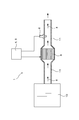
- FIG. 1 is a conceptual diagram of a particulate matter detection system in Embodiment 1.
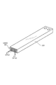
- FIG. FIG. 3 is a perspective view of a sensor main body according to the first embodiment.
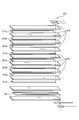
- FIG. 3 is an exploded perspective view of the sensor main body according to the first embodiment.
- FIG. 3 is a cross-sectional view of the particulate matter detection sensor according to the first embodiment.
- the graph showing the relationship between the temperature and time of heat_generation
- FIG. 3 is a partial cross-sectional view of the particulate matter detection sensor in the measurement mode in the first embodiment.
- the expanded sectional view of FIG. The expanded sectional view of the particulate matter detection sensor after the particulate matter and ash are removed in the first embodiment.
- 2 is a flowchart of the particulate matter detection system in the first embodiment.
- 3 is a graph showing a temperature distribution of a deposition target portion in the first embodiment. The graph showing the relationship between the electrical resistance of a heater and temperature.
- the particulate matter detection system can be an on-vehicle particulate matter detection system to be mounted on a vehicle such as a diesel vehicle or a gasoline engine vehicle.
- the particulate matter detection system 1 of this embodiment includes a particulate matter detection sensor 2, a control unit 4, and a temperature measurement unit 5.
- the particulate matter detection sensor 2 includes a portion 20 to be deposited, a pair of electrodes 21 (21 a and 21 b), and a heater 22.
- the particulate matter 3 in the exhaust gas g is deposited on the portion 20 to be deposited.
- the pair of electrodes 21a and 21b are provided in the deposition target portion 20 and are separated from each other.
- the heater 22 is provided for heating the portion 20 to be deposited.
- the control unit 4 is connected to the particulate matter detection sensor 2.
- the temperature measuring unit 5 measures the temperature of the deposition target part 20.
- the control unit 4 performs a measurement mode and a heat generation mode.
- the measurement mode is a mode in which the amount of the particulate matter 3 contained in the exhaust gas g is measured by measuring the current flowing between the pair of electrodes 21a and 21b.
- the heat generation mode is a mode in which the heater 22 generates heat and the particulate matter 3 deposited on the deposition target portion 20 is burned and removed.
- the control unit 4 is configured to control the temperature of the deposition target portion 20 measured by the temperature measurement unit 5 to be 600 to 750 ° C. in the heat generation mode.
- the particulate matter detection system 1 of this embodiment is an on-vehicle particulate matter detection system for mounting on a vehicle such as a diesel vehicle or a gasoline engine vehicle. As shown in FIG. 1, an exhaust pipe 11 through which exhaust gas g flows is connected to an engine 10 of a vehicle. The particulate matter detection sensor 2 is attached to the exhaust pipe 11. Further, a filter 6 that collects the particulate matter 3 is provided on the upstream side of the exhaust gas g from the particulate matter detection sensor 2.
- the particulate matter 3 in the exhaust gas g is collected using the filter 6, and the amount of the particulate matter 3 that has passed through the filter 6 is measured by the particulate matter detection sensor 2.
- the filter 6 is clogged with the particulate matter 3, the particulate matter 3 cannot be sufficiently collected. Therefore, the amount of the particulate matter 3 measured by the particulate matter detection sensor 2 increases.
- the amount of the particulate matter 3 in the exhaust gas g exceeds a predetermined value, it is determined that the filter 6 is clogged, and a filter heater (not shown) is caused to generate heat and collected by the filter 6.
- the particulate matter 3 formed is burned.
- the filter 6 is configured to be regenerated.
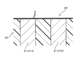
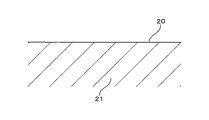
- the particulate matter detection sensor 2 includes a sensor body 23 having a quadrilateral plate shape.
- the electrodes 21 a and 21 b are exposed from the end surface 200 of the sensor body 23.
- the particulate matter 3 is deposited on the end surface 200 of the sensor main body 23. That is, the end surface 200 is the portion to be deposited 20.
- the sensor body 23 includes a plurality of insulating plates 24 made of ceramic. Between the plurality of insulating plates 24, the first electrode 21a and the second electrode 21b are interposed. A plurality of first electrodes 21a and second electrodes 21b are provided. The plurality of first electrodes 21 a are connected to each other by connection plugs (not shown) formed on the insulating plate 24. Similarly, the plurality of second electrodes 21b are also connected to each other by a connection plug.
- the sensor body 23 is provided with a heater 22.
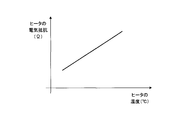
- the electrical resistance of the heater 22 changes. As shown in FIG. 13, there is a certain relationship between the temperature of the heater 22 and the resistance of the heater 22.
- the electrical resistance of the heater 22 is measured by the control unit 4, and the temperature of the heater 22, that is, the temperature of the deposition target portion 20 is calculated using the measured value.
- the particulate material 3 is mainly composed of carbon and has electrical conductivity. Therefore, as shown in FIG. 8, when the particulate matter 3 is deposited on the deposition target portion 20, a current flows between the electrodes 21a and 21b.
- the control unit 4 is configured to measure this current and calculate the amount of the particulate matter 3 in the exhaust gas g using the measured value.
- the control unit 4 If the particulate matter 3 is excessively deposited on the deposition target portion 20, the amount of current flowing between the electrodes 21a and 21b is saturated. Therefore, the amount of the particulate matter 3 in the exhaust gas g cannot be calculated. Therefore, in this case, the control unit 4 generates heat from the heater 22 (see FIG. 3), and burns and removes the particulate matter 3. Thereby, the particulate matter detection sensor 2 is regenerated.
- ash 7 is attached to the particulate matter 3.
- Ash 7 is obtained by oxidizing P, S, Ca, etc. contained in the engine oil.
- the ash 7 is made of, for example, CaSO 4 , Ca 3 (PO 4 ) 2 , Ca 2 P 2 O 7 , ZnO, Zn 3 (PO 4 ) 2, or the like.
- the melting point of these substances is usually 900 ° C. or higher, but may be 900 ° C. or lower when the quantum size effect or eutectic reaction occurs.
- the ash 7 becomes fine particles having a diameter of several nanometers, the melting point of the ash 7 is lowered due to the quantum size effect.
- fusing point of ash 7 falls by eutectic reaction. For these reasons, the melting point of ash 7 may be 900 ° C. or lower.
- the heating mode that is, when the heater 22 generates heat and the particulate matter 3 is burned and removed
- the temperature of the heater 22 is raised to about 900 ° C.
- the ash 7 is melted and shown in FIG.
- the ash 7 may be fused to the surface of the electrode 21. Since the ash 7 is an insulator, when the surface of the electrode 21 is covered with the ash 7, no current flows between the pair of electrodes 21a and 21b. Therefore, there is a possibility that the amount of the particulate matter 3 in the exhaust gas g cannot be accurately measured. Therefore, in this embodiment, when the heat generation mode is performed, the temperature of the heater 22, that is, the temperature of the deposited portion 20 is set to 600 to 750 ° C.
- the upper limit value of the temperature of the portion 20 to be deposited is 750 ° C., which is lower than the melting point of the ash 7 when the quantum size effect or the like occurs, so that the ash 7 can be prevented from melting in the heat generation mode. . Therefore, as shown in FIG. 10, the ash 7 can be prevented from being fused to the surface of the electrode 21.
- the temperature of the depositing part 20 in the heat generation mode is less than 600 ° C.
- the particulate matter 3 cannot be burned sufficiently, and there is a possibility that the unburned particulate matter 3 remains in the depositing part 20.
- the temperature of the deposited portion 20 in the heat generation mode is set to 600 to 750 ° C.
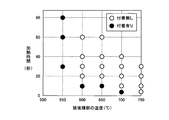
- the temperature of the deposition target portion 20 was changed to 550 ° C., 600 ° C., 650 ° C., 700 ° C., and 750 ° C. Further, the heat generation time was varied between 5 and 80 seconds. Then, the portion 20 to be deposited was observed to confirm whether the particulate matter 3 could be removed.
- the particulate matter 3 can be removed by heating for 20 seconds or more. Moreover, if the temperature of the part 20 to be deposited is 700 ° C., the particulate matter 3 can be removed by heating for 10 seconds or more. On the other hand, when the temperature of the portion to be deposited 20 is 550 ° C., the particulate matter 3 cannot be removed even if heated for 80 seconds. From this experimental result, it can be seen that the temperature of the deposition target portion 20 needs to be 600 ° C. or higher in order to sufficiently remove the particulate matter 3.
- the filter 6 was removed from the exhaust pipe 11 (see FIG. 1), and a large amount of the particulate matter 3 reached the particulate matter detection sensor 2 in a short time. Further, the sulfated ash content of the engine oil was 1.34% (usually 0.8%), and the amount of ash 7 generated was increased. As a result, the same amount of ash 7 as when the vehicle traveled 300,000 km reached the particulate matter detection sensor 2 in a short time.
- the heat generation mode and the measurement mode were alternately repeated while exposing the particulate matter detection sensor 2 to the exhaust gas g.
- the heating time for each sample in the exothermic mode was 210 seconds per cycle.
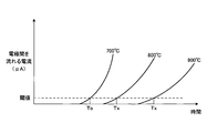
- a plurality of samples of the particulate matter detection sensor 2 are prepared. As shown in FIG. 6, the temperatures of the deposited portions 20 in the heat generation mode are 600 ° C., 700 ° C., 750 ° C., 800 ° C., 850 ° C., 900 Set to ° C.
- each sample is exposed to normal exhaust gas g in the concentration of particulate matter 3, and the current flowing between the pair of electrodes 21a and 21b is measured.
- the time change was measured.
- FIG. 7 for example, in a sample in which the temperature is set to 700 ° C. in the heat generation mode, current starts to flow between the electrodes 21a and 21b in a relatively short time after the measurement is started. This is presumably because the ash 7 is hardly fused on the surface of the electrode 21, so that a current flows between the electrodes 21 a and 21 b even if the particulate matter 3 is slightly deposited.
- the sample in which the temperature is set to 800 ° C. in the heat generation mode current does not start to flow unless a longer time elapses after the measurement starts than the sample at 700 ° C. This is presumably because the ash 7 is fused to the surface of the electrode 21 in the 800 ° C. sample.
- the time To until the current between the electrodes 21a and 21b reached a predetermined threshold value Io was measured.
- the time Tx until the current reached the threshold value Io was measured.
- the degradation rate d of each sample was computed using the following formula
- equation. d (Tx ⁇ To) / To ⁇ 100 (%)
- the sample having a temperature of 700 ° C. had a deterioration rate d of 0%.
- the deterioration rate d of each sample is shown in FIG.
- the deterioration rate d is almost 0% when the temperature of the deposited portion 20 in the heat generation mode is 750 ° C. or lower. It can also be seen that when the temperature exceeds 750 ° C., the deterioration rate d increases. This is because when the temperature in the heat generation mode exceeds 750 ° C., the ash 7 is fused to the electrode 21, so that the current hardly flows between the electrodes 21 a and 21 b, and the current starts to flow after starting the measurement mode. This is probably because it takes a long time to complete.
- the temperature of the deposition target 20 is set to 600 ° C. It turns out that it is necessary to control to 750 ° C.
- the particulate matter detection sensor 2 includes the sensor main body portion 23, a holding portion 81, a housing 25, and a fixing portion 26.
- the holding portion 81 is made of an insulating material such as ceramic.
- the sensor main body 23 is held in the holding portion 81. Further, the holding portion 81 is disposed in the housing 25.
- the housing 25 is inserted into the fixed portion 26.
- the male screw portion 261 of the fixing portion 26 is screwed into the female screw portion 110 formed in the exhaust pipe 11. Thereby, the particulate matter detection sensor 2 is fixed to the exhaust pipe 11.
- the housing 25 has a shoulder 251 formed therein.
- a spring member 83 is disposed on the tip side of the shoulder portion 251.
- the enlarged diameter portion 811 of the holding portion 81 is pressed against the reduced diameter portion 252 of the housing 25 using the applied pressure of the spring member 83.
- the exhaust gas g is prevented from leaking from between the enlarged diameter portion 811 and the reduced diameter portion 252.
- the particulate matter detection sensor 2 includes an electrode wiring 291 and a heater wiring 292. These wirings 291 and 292 are provided in pairs.
- the electrode wiring 291 is electrically connected to the electrodes 21 a and 21 b in the sensor main body 23.
- the heater wiring 292 is electrically connected to the heater 22.
- the tip of the sensor body 23 is protected by two covers 27 and 28, an inner cover 27 and an outer cover 28.
- the outer cover 28 includes a bottom portion 282 and a side wall portion 281. Through holes 283 and 284 are formed in the side wall portion 281 at positions close to the bottom portion 282.
- a through hole (inner side through hole 273) is also formed in the inner cover 27.
- An opening 272 is formed in the inner cover 27.
- the opening 272 is formed between the deposition target portion 20 and the bottom portion 282 and opens in the longitudinal direction (Z direction) of the sensor main body 23.
- the inner cover 27 is formed with a guide plate 271 for guiding the exhaust gas g.
- Exhaust gas g passes through the inner side through hole 273 after passing through the upstream side through hole 283 of the outer cover 28, hitting the side wall 281, and changing its direction. At this time, the exhaust gas g is guided to the portion 20 to be deposited by the guide plate 271. As a result, more exhaust gas g hits the portion 20 to be deposited. Thereby, the responsiveness of the particulate matter detection sensor 2 is enhanced.
- the exhaust gas g hits the deposition target portion 20, passes through the opening 272, passes through the downstream side through hole 284, and is discharged to the outside of the outer cover 28.
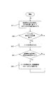
- control unit 4 first measures the current between the electrodes 21a and 21b of the particulate matter detection sensor 2, and calculates the amount of the particulate matter 3 in the exhaust gas g based on the measured value. (Step S1; measurement mode).
- control unit 4 determines whether or not it is necessary to regenerate the filter 6 (step S2). If it is determined YES, the process proceeds to step S3. Then, the filter heater is heated to burn the particulate matter 3 collected by the filter 6. Thereby, the filter 6 is regenerated.
- control unit 4 determines whether or not the current value between the electrodes 21a and 21b exceeds a predetermined value, that is, whether or not the current is saturated (step S4). If it is determined YES, the process proceeds to step S5. Here, the heater 22 is heated, and the particulate matter 3 deposited on the deposition target portion 20 is burned and removed (heat generation mode). At this time, the control unit 4 sets the temperature of the heater 22, that is, the temperature of the deposition target portion 20 to 600 to 750 ° C.
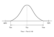
- the temperature in the deposition target part 20 is not uniform, and there are a part where the temperature is high and a part where the temperature is low.
- the difference between the maximum temperature T max and the minimum temperature T min in the deposition target portion 20 is set to be within 100 ° C. That is, the difference between the average temperature T typ and the maximum temperature T max is set to 50 ° C. or less, and the difference between the average temperature T typ and the minimum temperature T min is set to 50 ° C. or less.
- the temperature of the deposition target portion 20 is controlled to 600 to 750 ° C. Therefore, it is possible to suppress the ash 7 from being fused to the surface of the electrode 21. That is, as described above, the ash 7 may have a melting point of 900 ° C. or lower due to the quantum size effect or eutectic reaction, but hardly reaches 750 ° C. or lower. Therefore, by setting the upper limit of the temperature of the deposited portion to 750 ° C., it is possible to suppress ash fusion on the surface of the electrode.
- the lower limit value of the temperature of the deposited portion in the heat generation mode is set to 600 ° C. Therefore, in the heat generation mode, the problem that the particulate matter does not burn and the particulate matter remains between the electrodes 21a and 21b can be suppressed.
- the temperature difference (T max ⁇ T min ) between the highest temperature portion and the lowest temperature portion in the deposited portion 20 is set to 100 ° C. or less. Therefore, there is a margin between the maximum temperature T max and 750 ° C. and between the minimum temperature T min and 600 ° C., and any part of the deposited portion 20 can be reliably set to 600 to 750 ° C. become.
- the temperature of the depositing portion 20 is likely to change depending on the temperature and flow rate of the exhaust gas g. However, if T max ⁇ T min ⁇ 100 (° C.), even if the temperature or flow rate of the exhaust gas g changes suddenly in the heat generation mode. Thus, it becomes easy to set all the parts of the deposited portion 20 to 600 to 750 ° C.
- the sensor main body 23 of the particulate matter detection sensor 2 is formed in a quadrangular plate shape.
- the end surface 200 of the sensor main body 23 is a deposition target portion 20. Therefore, the area of the deposition target portion 20 can be reduced, and the temperature variation in the deposition target portion 20 can be reduced. Therefore, in the heat generation mode, all the parts of the deposition target portion 20 are likely to be 600 to 750 ° C.
- a guide plate 271 that guides the exhaust gas g to the deposited portion 20 is formed on the inner cover 27 of the particulate matter detection sensor 2. Therefore, the exhaust gas g is likely to hit the portion 20 to be deposited, and the responsiveness of the particulate matter detection sensor 2 can be improved. In this way, the particulate matter 3 is likely to be deposited on the portion 20 to be deposited, and the ash 7 is also likely to be deposited on the portion 20 to be deposited together with the particulate matter 3 (see FIG. 8).
- the upper limit value of the temperature of the portion 20 to be deposited in the heat generation mode is set to 750 ° C., the ash 7 is melted and fused to the electrode 21 even when the amount of ash 7 deposited is increased. Is unlikely to occur.
- a filter 6 is provided on the upstream side of the exhaust gas g from the particulate matter detection sensor 2.
- the filter 6 has a particulate matter 3 collection efficiency of 98% or less. Therefore, the pressure loss of the exhaust gas g can be reduced. That is, the collection efficiency of the filter 6 is generally 99.9% or more. Therefore, as long as the filter 6 does not fail, the amounts of the particulate matter 3 and the ash 7 that reach the particulate matter detection sensor 2 are very small.
- such a filter 6 having a high collection efficiency has a high pressure loss of the exhaust gas g, and the fuel consumption of the engine 10 is likely to decrease.
- the collection efficiency of the filter 6 is 98% or less as in the present embodiment, the pressure loss of the exhaust gas g can be reduced, and the reduction in fuel consumption can be suppressed.
- the collection efficiency of the filter 6 is reduced, the amount of the particulate matter 3 and the ash 7 that reach the particulate matter detection sensor 2 increases.
- the temperature of the deposition target portion 20 in the heat generation mode is increased. Since the upper limit of 750 ° C. is set, even if the amount of ash 7 increases, it is possible to suppress the fusion of a large amount of ash 7 to the electrode 21.
- the collection efficiency of the filter 6 is preferably 80% or less.
- the collection efficiency is 80% or less, the pressure loss of the filter 6 can be further reduced, and the fuel consumption can be further suppressed.
- the collection efficiency of the filter 6 is more preferably 60% or less.
- the collection efficiency is 60% or less, the pressure loss of the filter 6 can be further reduced, and the fuel consumption can be further suppressed.
- control unit 4 and the temperature measurement unit 5 are integrated. That is, the electrical resistance of the heater 22 is measured by the control unit 4, and the temperature of the heater 22, that is, the temperature of the deposition target portion 20 is calculated using the measured value.
- the present invention is not limited to this, and a dedicated temperature sensor may be provided as the temperature measuring unit 5.
Landscapes
- Engineering & Computer Science (AREA)
- Chemical & Material Sciences (AREA)
- Combustion & Propulsion (AREA)
- Mechanical Engineering (AREA)
- General Engineering & Computer Science (AREA)
- Chemical Kinetics & Catalysis (AREA)
- Health & Medical Sciences (AREA)
- Toxicology (AREA)
- Exhaust Gas After Treatment (AREA)
- Processes For Solid Components From Exhaust (AREA)
- Investigating Or Analyzing Materials By The Use Of Electric Means (AREA)
Applications Claiming Priority (2)
| Application Number | Priority Date | Filing Date | Title |
|---|---|---|---|
| JP2015162665A JP6501672B2 (ja) | 2015-08-20 | 2015-08-20 | 粒子状物質検出システム |
| JP2015-162665 | 2015-08-20 |
Publications (1)
| Publication Number | Publication Date |
|---|---|
| WO2017029948A1 true WO2017029948A1 (ja) | 2017-02-23 |
Family
ID=58052191
Family Applications (1)
| Application Number | Title | Priority Date | Filing Date |
|---|---|---|---|
| PCT/JP2016/071682 Ceased WO2017029948A1 (ja) | 2015-08-20 | 2016-07-25 | 粒子状物質検出システム |
Country Status (2)
| Country | Link |
|---|---|
| JP (1) | JP6501672B2 (enExample) |
| WO (1) | WO2017029948A1 (enExample) |
Families Citing this family (2)
| Publication number | Priority date | Publication date | Assignee | Title |
|---|---|---|---|---|
| JP6358226B2 (ja) | 2015-10-21 | 2018-07-18 | 株式会社デンソー | 粒子状物質検出装置 |
| DE102021116420A1 (de) * | 2021-06-25 | 2022-12-29 | Purem GmbH | Verbindungsanordnung |
Citations (4)
| Publication number | Priority date | Publication date | Assignee | Title |
|---|---|---|---|---|
| JP2010151554A (ja) * | 2008-12-24 | 2010-07-08 | Honda Motor Co Ltd | 粒子状物質検出装置 |
| JP2011224538A (ja) * | 2009-12-01 | 2011-11-10 | Ibiden Co Ltd | ハニカムフィルタ及び排ガス浄化装置 |
| WO2012124054A1 (ja) * | 2011-03-15 | 2012-09-20 | トヨタ自動車株式会社 | 内燃機関の制御装置 |
| WO2013076869A1 (ja) * | 2011-11-25 | 2013-05-30 | トヨタ自動車株式会社 | 内燃機関の制御装置 |
Family Cites Families (2)
| Publication number | Priority date | Publication date | Assignee | Title |
|---|---|---|---|---|
| JP5500028B2 (ja) * | 2010-09-30 | 2014-05-21 | 株式会社デンソー | 粒子状物質検出センサの製造方法 |
| JP5606356B2 (ja) * | 2011-02-17 | 2014-10-15 | 株式会社日本自動車部品総合研究所 | 粒子状物質検出装置 |
-
2015
- 2015-08-20 JP JP2015162665A patent/JP6501672B2/ja active Active
-
2016
- 2016-07-25 WO PCT/JP2016/071682 patent/WO2017029948A1/ja not_active Ceased
Patent Citations (4)
| Publication number | Priority date | Publication date | Assignee | Title |
|---|---|---|---|---|
| JP2010151554A (ja) * | 2008-12-24 | 2010-07-08 | Honda Motor Co Ltd | 粒子状物質検出装置 |
| JP2011224538A (ja) * | 2009-12-01 | 2011-11-10 | Ibiden Co Ltd | ハニカムフィルタ及び排ガス浄化装置 |
| WO2012124054A1 (ja) * | 2011-03-15 | 2012-09-20 | トヨタ自動車株式会社 | 内燃機関の制御装置 |
| WO2013076869A1 (ja) * | 2011-11-25 | 2013-05-30 | トヨタ自動車株式会社 | 内燃機関の制御装置 |
Also Published As
| Publication number | Publication date |
|---|---|
| JP2017040214A (ja) | 2017-02-23 |
| JP6501672B2 (ja) | 2019-04-17 |
Similar Documents
| Publication | Publication Date | Title |
|---|---|---|
| JP5240679B2 (ja) | 検出装置 | |
| KR102190273B1 (ko) | 입자 센서를 작동시키기 위한 방법 및 장치 | |
| JP6426072B2 (ja) | フィルタの故障検出装置、粒子状物質検出装置 | |
| CN105402012B (zh) | 微粒过滤器的异常诊断装置 | |
| JP6207158B2 (ja) | 煤粒子センサシステム | |
| JP2009144577A (ja) | パティキュレートフィルタの故障判定装置 | |
| US20120186230A1 (en) | Detection apparatus | |
| WO2012023182A1 (ja) | 内燃機関の制御装置 | |
| JP2008032686A (ja) | 煤センサ | |
| JP6248964B2 (ja) | 粒子状物質検出装置 | |
| JP2015175321A (ja) | フィルタの故障検出装置及び粒子状物質検出装置 | |
| JPS59196453A (ja) | パテイキユレ−ト検出素子 | |
| JP6358226B2 (ja) | 粒子状物質検出装置 | |
| WO2017029948A1 (ja) | 粒子状物質検出システム | |
| US20170199111A1 (en) | Method for operating a particle sensor | |
| JP6481966B2 (ja) | 制御装置 | |
| JP6440834B2 (ja) | 粒子を検出するセンサの機能制御のための方法 | |
| WO2016147711A1 (ja) | 粒子状物質検出システム | |
| WO2016052734A1 (ja) | フィルタの故障検出装置、粒子状物質検出装置 | |
| JP6444063B2 (ja) | 粒子状物質検出装置及び粒子状物質検出方法 | |
| JP6481967B2 (ja) | 制御装置 | |
| JP6552444B2 (ja) | 粒子状物質検出装置及び内燃機関の排ガス浄化装置 | |
| JP6207350B2 (ja) | 粒子センサの温度制御装置 | |
| CN108885163B (zh) | 颗粒状物质检测装置 | |
| JP6421736B2 (ja) | 粒子状物質検出装置 |
Legal Events
| Date | Code | Title | Description |
|---|---|---|---|
| 121 | Ep: the epo has been informed by wipo that ep was designated in this application |
Ref document number: 16836939 Country of ref document: EP Kind code of ref document: A1 |
|
| NENP | Non-entry into the national phase |
Ref country code: DE |
|
| 122 | Ep: pct application non-entry in european phase |
Ref document number: 16836939 Country of ref document: EP Kind code of ref document: A1 |