WO2017026201A1 - ケーブル盗難防止方法、ケーブルの盗難防止構造およびトラフ線路 - Google Patents
ケーブル盗難防止方法、ケーブルの盗難防止構造およびトラフ線路 Download PDFInfo
- Publication number
- WO2017026201A1 WO2017026201A1 PCT/JP2016/069702 JP2016069702W WO2017026201A1 WO 2017026201 A1 WO2017026201 A1 WO 2017026201A1 JP 2016069702 W JP2016069702 W JP 2016069702W WO 2017026201 A1 WO2017026201 A1 WO 2017026201A1
- Authority
- WO
- WIPO (PCT)
- Prior art keywords
- cable
- trough
- elastic member
- resin foam
- trough lid
- Prior art date
- Legal status (The legal status is an assumption and is not a legal conclusion. Google has not performed a legal analysis and makes no representation as to the accuracy of the status listed.)
- Ceased
Links
Images







Classifications
-
- H—ELECTRICITY
- H02—GENERATION; CONVERSION OR DISTRIBUTION OF ELECTRIC POWER
- H02G—INSTALLATION OF ELECTRIC CABLES OR LINES, OR OF COMBINED OPTICAL AND ELECTRIC CABLES OR LINES
- H02G9/00—Installations of electric cables or lines in or on the ground or water
- H02G9/04—Installations of electric cables or lines in or on the ground or water in surface ducts; Ducts or covers therefor
-
- B—PERFORMING OPERATIONS; TRANSPORTING
- B60—VEHICLES IN GENERAL
- B60M—POWER SUPPLY LINES, AND DEVICES ALONG RAILS, FOR ELECTRICALLY- PROPELLED VEHICLES
- B60M1/00—Power supply lines for contact with collector on vehicle
- B60M1/02—Details
-
- H—ELECTRICITY
- H02—GENERATION; CONVERSION OR DISTRIBUTION OF ELECTRIC POWER
- H02G—INSTALLATION OF ELECTRIC CABLES OR LINES, OR OF COMBINED OPTICAL AND ELECTRIC CABLES OR LINES
- H02G1/00—Methods or apparatus specially adapted for installing, maintaining, repairing or dismantling electric cables or lines
- H02G1/06—Methods or apparatus specially adapted for installing, maintaining, repairing or dismantling electric cables or lines for laying cables, e.g. laying apparatus on vehicle
-
- B—PERFORMING OPERATIONS; TRANSPORTING
- B60—VEHICLES IN GENERAL
- B60M—POWER SUPPLY LINES, AND DEVICES ALONG RAILS, FOR ELECTRICALLY- PROPELLED VEHICLES
- B60M2200/00—Specific problems related to power supply lines not otherwise provided for
- B60M2200/02—Prevention of theft of valuable metals
-
- B—PERFORMING OPERATIONS; TRANSPORTING
- B60—VEHICLES IN GENERAL
- B60M—POWER SUPPLY LINES, AND DEVICES ALONG RAILS, FOR ELECTRICALLY- PROPELLED VEHICLES
- B60M5/00—Arrangements along running rails or at joints thereof for current conduction or insulation, e.g. safety devices for reducing earth currents
-
- H—ELECTRICITY
- H02—GENERATION; CONVERSION OR DISTRIBUTION OF ELECTRIC POWER
- H02G—INSTALLATION OF ELECTRIC CABLES OR LINES, OR OF COMBINED OPTICAL AND ELECTRIC CABLES OR LINES
- H02G2200/00—Indexing scheme relating to installation of electric cables or lines covered by H02G
- H02G2200/10—Prevention of theft of valuable metals
-
- H—ELECTRICITY
- H02—GENERATION; CONVERSION OR DISTRIBUTION OF ELECTRIC POWER
- H02G—INSTALLATION OF ELECTRIC CABLES OR LINES, OR OF COMBINED OPTICAL AND ELECTRIC CABLES OR LINES
- H02G3/00—Installations of electric cables or lines or protective tubing therefor in or on buildings, equivalent structures or vehicles
- H02G3/02—Details
- H02G3/04—Protective tubing or conduits, e.g. cable ladders or cable troughs
- H02G3/0406—Details thereof
- H02G3/0418—Covers or lids; Their fastenings
Definitions
- the present invention relates to a cable theft prevention method, a cable theft prevention structure, and a trough track accommodated in a trough.
- resin troughs are laid along the tracks and roads, and various cables are stored inside.
- a trough is usually fixed with a lid to prevent intrusion of foreign matter into the inside or tampering with a cable or the like.
- a lid is fixed by a fixing band or the like (for example, Patent Document 1).
- a fixing structure has been proposed in which a fixing bracket is attached to the trough body and the trough lid is firmly fixed to the trough with bolts or the like.
- the fixing brackets are attached to both sides of the trough, and the trough lid is fixed to the trough by inserting the bolt from above the trough lid and fixing the bolt to the nut portion of the fixing member with the trough lid closed.
- Patent Document 2 There is a fixed structure (Patent Document 2).
- the present invention has been made in view of such problems, and an object of the present invention is to provide a cable theft prevention method, a cable theft prevention structure, and a trough line that make cable theft difficult.
- the first invention provides an elastic member disposed between a cable disposed inside the trough main body and a trough lid that closes an upper portion of the trough main body, and a rear surface of the trough lid. And the elastic member are in contact with each other, and the cable is pressed with the elastic member by pressing the elastic member with the back surface of the trough lid.
- the elastic member a resin sheet, a rubber member (rubber sheet, rubber having a block shape), a resin foam, or the like can be used, but the elastic member is used in terms of cost, workability, adjustment of pressing force, and the like.
- a resin foam is desirable.
- the resin foam has two end surfaces, one end surface of the resin foam is brought into contact with the back surface of the trough lid, and the cable is pressed by the other end surface of the resin foam.
- a plurality of reinforcing ribs are formed on the back surface of the trough lid, and the resin foam is inserted and fixed between the reinforcing ribs on the back surface of the trough lid, or the resin foam is pressed.
- the resin foam may be pressed by contacting the tip of the reinforcing rib.
- the reinforcing rib may be a reinforcing rib parallel to the longitudinal direction of the trough lid and / or a reinforcing rib parallel to the width direction of the trough lid.
- the elastic member When the elastic member is pressed by the reinforcing rib as described above, it can be pressed by both the reinforcing rib parallel to the longitudinal direction of the trough lid and the reinforcing rib parallel to the width direction of the trough lid.
- the resin foam may be a substantially rectangular parallelepiped, and the lengths of three sides perpendicular to each other of the elastic member may be different from each other. If a rectangular parallelepiped elastic member having three different lengths is used in this way, either side of the elastic member is pressed against the cable disposed in the trough and the distance between the rear surface of the trough lid and the tip of the reinforcing rib. It can be selected whether to arrange in the direction of exerting.
- a plurality of the cables may be arranged inside the trough body, and the plurality of cables may be bundled with a bundling member. By binding the cables in this way, the cable existing in the uppermost layer or the largest cable can be pressed and all the cables arranged in the trough can be fixed in the trough.
- the resin foam may be a laminated structure composed of a plurality of resin foams.
- the laminated structure a laminated structure made up of a plurality of elastic bodies, the number of laminated elastic bodies arranged in the trough can be changed, and the height of the pressing member can be easily adjusted. .
- the laminated structure may include at least one of a hard resin foam and a soft resin foam.
- a hard resin foam may be combined, or soft resin foams may be combined, or a combination of a hard resin foam and a soft resin foam may be used.
- strength of the hard resin foams to be used or the soft resin foam to be used can also be changed.
- the laminated structure is obtained by laminating the soft resin foam on a surface layer of a hard resin foam, the soft resin foam is brought into contact with the cable, and the hard resin foam is brought into contact with the trough lid side. May be.
- the layers may be bonded to each other with an adhesive or a pressure-sensitive adhesive.
- the resin foam used for the laminated structure can be used according to a resin material using an epoxy adhesive, a urethane adhesive, a polyester adhesive, an emulsion adhesive, or the like. Alternatively, a hot melt adhesive can be used. Moreover, a rubber-type solvent-type adhesive agent, an emulsion-type adhesive agent, etc. can be used for a rubber-type resin foam.
- the adhesive of a laminated structure can use the adhesive which can adhere
- the resin foam preferably has an elastic repulsion force of 15 kPa or more and 50 kPa or less at 25% compression deformation.
- the elastic repulsion force of the resin foam at the time of 25% compression deformation in the present invention is used synonymously with the force having the same magnitude and the opposite direction of the compression stress when the resin foam is subjected to 25% compression deformation. be able to.
- the compression stress required when the resin foam is deformed by 25% is not a problem, but the elastic repulsion force exerted on the cable by the resin foam and the change in the contact area between the resin foam and the cable. Therefore, in the following, the expression “elastic repulsive force at the time of 25% compression deformation” will be mainly used.
- the elastic member may be bonded to the trough lid. By doing in this way, an elastic member can be fixed to a trough cover, and when an extraction force is given to a cable in a trough, an elastic member can be made difficult to shift.
- the elastic member may be made of any resin foam or rubber foam of polyethylene resin, polypropylene resin, polystyrene resin, polyurethane resin, PVC resin, EVA resin, EPDM rubber, nitrilo rubber, acrylic rubber, and chloroprene rubber.
- polyolefin resin foams such as polyethylene resin and polypropylene resin which are general purpose resins.
- the trough lid fixing member may be used to fix the trough lid to the trough body, and the trough lid fixing member may press the trough lid to press the elastic member against the cable.
- the pull-out resistance of the cable can be increased by the contact between the cable and the elastic member. As a result, it becomes difficult to pull the cable out from the trough in one direction. For this reason, it can suppress that a cable is stolen.
- the elastic member is a resin foam, it is lightweight and easy to work. Moreover, since it can be set as the range of the moderate deformation force which closes a trough lid
- the upper and lower surfaces of the resin foam as an elastic member are brought into contact with the back surface of the trough lid and the cable, and the resin foam is pressed with the trough lid, so that the cable can be reliably pressed from above.
- the reinforcing rib performs both functions of reinforcing the trough lid and fixing the resin foam. . Further, by using the reinforcing rib, it is easy to fix the resin foam as an elastic member to the trough lid.
- the reinforcing rib is made of a reinforcing rib parallel to the longitudinal direction of the trough lid and / or a reinforcing rib parallel to the width direction of the trough lid, so that the resin foam, which is an elastic member having a substantially rectangular cross-sectional shape, is used as the reinforcing rib. Can be easily fixed between. Further, depending on the size of the resin foam and the arrangement of the ribs of the trough lid, the tip of the reinforcing rib can be brought into contact with the surface of the resin foam, and the resin foam can be pressed by the tip of the reinforcing rib.
- the resin foam as the elastic member is a substantially rectangular parallelepiped, and the lengths of the three orthogonal sides of the elastic member are different from each other, the elastic member can be changed from the rear surface of the trough lid by changing the fixing direction of the elastic member. The amount of protrusion can be easily changed. For this reason, the same resin foam can be utilized when the number of cables laid inside the trough body is different or for the sizes of a plurality of troughs.
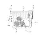
- the cables can be prevented from being displaced by bundling the cables with a bundling member. For this reason, it can prevent that it becomes impossible to maintain the pressing force to the cable from the resin foam as an elastic member by position shift of cables. Further, it is possible to prevent a cable that does not come into contact with the elastic member or a cable with a weak pressing force from the elastic member from being easily pulled out. In this way, by bundling multiple cables with a bundling member, all cables must be pulled out at the same time. Therefore, in addition to the pressing force exerted on the cable by the elastic member, a pulling force that superimposes the weight of all cables is required. Thus, the cable cannot be pulled out easily.
- the resin foam as the elastic member may be a laminated structure composed of a plurality of layers of resin foam.
- the laminated structure may be formed by laminating only hard resin foams. In this case, the thickness of the elastic member can be easily changed by changing the number of layers.
- the thickness and number of layers of the resin foam are adjusted so that the laminated structure includes a hard resin foam and a soft resin foam so that the pressing force is suitable for pressing the cable.
- the contact area between the resin foam and the cable can be increased and the entire cable can be pressed.
- the pressing force from a trough lid can be more reliably transmitted to a cable by making the back surface of a trough lid and a hard resin foam contact.
- each layer of the laminated structure is bonded with an adhesive or a pressure-sensitive adhesive, the thickness of the laminated structure can be easily adjusted in the field according to the capacity of the cable in the trough and the trough size. .
- the elastic member can be more securely fixed to the trough lid by adhering the elastic member to the trough lid.
- the elastic member is polyethylene resin, polyurethane resin, polystyrene resin, polypropylene resin, PVC (Polyvinyl Chloride) resin, EVA (Ethylene-Vinyl Acetate) resin, EPDM (Ethylene-propylene methylene linkage) rubber, nitrilo rubber, A resin foam of chloroprene rubber is suitable for pressing the cable.
- the elastic member can be more reliably pressed against the cable by pressing the trough lid with the trough lid fixing member.
- the second invention includes a trough body, a trough lid that covers an upper portion of the trough body, is fixed to the trough body, a cable that is disposed inside the trough body, and a cable pressing member that presses the cable. And a pressing force applying member that applies a pressing force to the cable pressing member, wherein the cable pressing member is disposed between the cable and the trough lid, and the cable pressing member includes the trough lid The cable pressing member is pressed against the cable via the trough lid when the trough lid is pressed by the pressing force applying member.
- a cable antitheft structure characterized by the above.
- the pressing force applying member may be a trough lid fixing member that fixes the trough lid to the trough body, and the trough lid fixing member may be a fixing bolt, a fixing buckle, or a fixing band.
- a third invention is a trough track in which the cable antitheft structure according to the second invention is provided at a plurality of locations in a trough track in which a plurality of the trough main bodies and the trough lid are connected. .
- the number of arrangement is determined in accordance with the design of the pull-out force per predetermined length of the cable.
- the present invention it is possible to provide a cable theft prevention method, a cable theft prevention structure, and a trough line that make it difficult for the cable to be stolen.
- FIG. 4 is a cross-sectional view of the cable theft prevention structure 1d. Sectional drawing of the cable antitheft structure 1e. Sectional drawing of the cable antitheft structure 1 when not using the binding member 12. FIG. Sectional drawing of the cable antitheft structure 1 when not using the binding member 12. FIG. Sectional drawing of the cable antitheft structure 1 using the binding member 12. FIG. The perspective view which shows the elastic member 7. FIG. The back view of the trough cover 5. FIG. The rear view of the other aspect of the trough cover 5. FIG.
- FIG. The rear view of the other aspect of the trough cover 5.
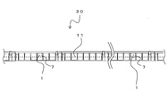
- FIG. The figure which shows the trough track 30.
- FIG. The figure which shows the elastic member 7a.
- Sectional drawing of the cable antitheft structure 1b Sectional drawing of the cable antitheft structure 1b.
- the figure which shows the elastic member 7b Sectional drawing of the cable antitheft structure 1c.
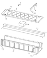
- FIG. 1 is an exploded perspective view showing a cable theft prevention structure 1 according to the present invention
- FIG. 2 is an assembly perspective view showing the cable theft prevention structure 1.
- the cable trough mainly consists of a trough body 3 and a trough lid 5.
- the trough body 3 and the trough lid 5 are made of resin, for example, and are molded by press molding or injection molding.
- the trough body 3 and the trough lid 5 have a length of about 1 m, for example.
- fitting portions 13a and 13b are provided, respectively.
- the fitting portion 13 a has a groove on the inner surface side of the trough body 3, and the fitting portion 13 b has a protrusion corresponding to the groove on the outer surface side of the trough body 3.
- the trough main bodies 3 can be connected to each other by fitting the fitting portions 13a of one trough main body 3 and the fitting portions 13b of other adjacent trough main bodies 3 together.
- the trough lid 5 closes the upper part of the trough body 3.
- the trough lid 5 is fixed to the trough body 3 by a trough lid fixing member 9.
- the trough lid fixing member 9 is a metal fixing band.
- the trough lid fixing member 9 is formed by bending a plate-shaped metal plate, and both ends of the top plate portion are bent substantially perpendicular to the top plate portion to form a pair of leg portions. That is, the trough lid fixing member 9 has a generally inverted U shape.
- each leg-shaped part is bent to become a locking part 21.
- a fixing portion 15 is formed on the outer surface of the trough body 3. With the trough lid 5 disposed on the trough body 3, the trough lid fixing member 9 is attached from above the trough lid 5, and the locking portion 21 is hooked on the fixing portion 15 of the trough body 3. It is fixed to the main body 3.
- the cable 11 is disposed inside the trough body 3.
- a plurality of cables 11 (three examples are shown in the figure) are accommodated in the trough body 3.
- An elastic member 7 that is a cable pressing member is provided between the trough lid 5 and the cable 11.
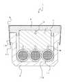
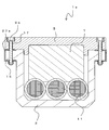
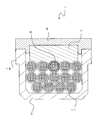
- FIG. 3 is a cross-sectional view perpendicular to the longitudinal direction of the cable anti-theft structure 1.
- the elastic member 7 has two opposing end surfaces, and one end surface (upper surface) is in contact with the back surface of the trough lid 5. The other end surface (lower surface) of the elastic member 7 is in contact with the upper surface of the cable 11.
- the elastic member 7 is pressed from the back surface of the trough lid 5 (arrow A in the figure).
- the elastic member 7 presses the cable 11 with elastic deformation (arrow B in the figure). That is, the thickness of the elastic member 7 before elastic deformation is thicker than the distance between the back surface of the trough lid 5 and the upper end of the cable 11.
- the trough lid 5 is fixed to the trough body 3 by the trough lid fixing member 9. Therefore, by pressing the trough lid 5 with the trough lid fixing member 9, the trough lid 5 does not float from the trough body 3 due to the repulsive force of the elastic member 7. Further, the elastic member 7 can be reliably pressed against the cable 11 via the trough lid 5 by the trough lid fixing member 9. That is, the trough lid fixing member 9 functions as a pressing force applying member that applies a pressing force to the elastic member 7.
- the trough lid 5 is provided with a hole 17 and a groove 19 (see FIGS. 1 and 2), and the trough lid 5 can be fixed using these.
- a pair of grooves 19 are provided in the vicinity of both side portions on the upper surface of the trough lid 5.
- the groove 19 is provided in a portion corresponding to the fixing portion 15 of the trough body 3 in a state where the trough lid 5 is closed.
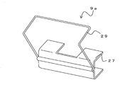
- FIG. 4A shows the trough lid fixing member 9a.
- the trough lid fixing member 9 a includes a gripping member 27 and a buckle 29. That is, the trough lid fixing member 9a is a fixed buckle.
- the gripping member 27 has upper and lower gripping portions that are substantially parallel to each other, and the fixing portion 15 can be sandwiched between the upper and lower gripping portions.
- a hole or a notch (the figure shows an example of a notch) is provided in the upper grip portion of the grip member 27.
- the gripping member 27 is fixed so that the fixing portion 15 is sandwiched between the upper and lower gripping portions.
- the buckle 29 is rotated above the trough lid 5 with respect to the gripping member 27 in this state, the buckle 29 is fitted into the groove 19 on the upper surface of the trough lid 5. Therefore, the trough lid 5 can be fixed to the trough body 3.
- the trough lid 5 can be fixed to the trough body 3 even if the trough lid fixing member 9a is used. Therefore, the trough lid fixing member 9a can prevent the trough lid 5 from floating from the trough body 3. As a result, the trough lid 5 can be pressed against the elastic member 7, and the cable 11 can be pressed by the elastic member 7.
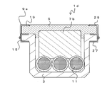
- FIG. 5 is a diagram showing a cable theft prevention structure 1e using the trough lid fixing member 9b.
- the hole 17 is a through hole provided in a portion corresponding to the fixing portion 15 of the trough body 3.
- the trough lid fixing member 9b is a fixing bolt.
- the holding member 27a is attached to the fixing portion 15 of the trough body 3 from both sides. Similar to the gripping member 27, the gripping member 27 a is formed so that the gripping portions are substantially parallel to each other, and is fixed so that the fixing portion 15 is sandwiched between the top and bottom gripping portions. A hole or notch is provided in the upper grip portion of the grip member 27a.
- the nut part is provided in the lower holding part of the holding member 27a.
- the nut portion is, for example, a cap nut.
- the trough lid 5 can be fixed to the trough body 3 by inserting the trough lid fixing member 9b from above the hole 17. Therefore, the trough lid fixing member 9b can prevent the trough lid 5 from floating from the trough body 3. As a result, the trough lid 5 can be pressed against the elastic member 7, and the cable 11 can be pressed by the elastic member 7.
- the hole 17 is a counterbore, and the head of the trough lid fixing member 9 b does not protrude from the upper surface of the trough lid 5.
- the trough lid 5 can be fixed to the trough body 3, it can function as a pressing force applying member that applies a pressing force to the elastic member 7.
- a pressing force applying member that applies a pressing force to the elastic member 7.
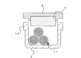
- the cables 11 are arranged in a plurality of stages, and the lower cables 11 may have a margin in the width direction of the trough body 3. In this case, if the trough lid 5 is closed and the upper cable 11 is pressed by the elastic member 7, the cable 11 may move as shown in FIG. 6B (arrow C in the figure).
- the cables 11 are moved by moving some of the cables 11 arranged in the trough body 3. And the distance between the elastic members 7 may vary.
- the number and size of the cables 11 inside the trough body 3 vary depending on the laying section and the site. Therefore, it is necessary to adjust the required thickness of the elastic member 7 according to the laying section and the site. That is, in order to appropriately press the cable 11 with a pressing force, it is desirable to apply the elastic member 7 having an appropriate size according to the size and number of the cables 11. That is, it is desirable to change the size of the elastic member 7 in accordance with the distance from the trough lid 5 to the upper surface of the cable 11.
- the elastic member 7 of this embodiment is a substantially rectangular parallelepiped as shown in FIG. Further, the lengths of three sides orthogonal to each other (E, F, G in the figure) are different from each other. Therefore, even if it is the same elastic member 7, the protrusion length from the back surface of the trough lid
- the elastic member 7 may be an elastically deformable member, but is preferably a resin material.
- rubber or resin (rubber) foam is applicable.
- the resin foam include polyethylene resin, polyurethane resin, polystyrene resin, polypropylene resin, PVC (Polyvinyl Chloride) resin, EVA (Ethylene-Vinyl Acetate) resin, EPDM (Ethylene-propylene diene methylene rubber) acrylic rubber, It is desirable to be a resin foam of any of rubber and chloroprene rubber, a rubber foam, or a mixture thereof.
- the elastic member 7 is a resin foam, it is lightweight and a sufficient amount of elastic deformation can be secured. For this reason, the contact area of the elastic member 7 and the surface of the cable 11 is securable.
- a resin foam having an elastic repulsion force of 30 kPa or more at 25% compression deformation is defined as a hard resin foam
- a resin foam having an elastic repulsion force at 25% compression deformation of less than 30 kPa is defined as a soft resin foam.
- a hard resin foam and a soft resin foam having an elastic repulsion force in a range of 15 kPa to 50 kPa can be used.
- a soft resin foam of 15 kPa or more and less than 30 kPa, or a hard resin foam of 30 kPa or more and 50 kPa or less can be used. This is because when the elastic repulsion force exceeds 50 kPa, it becomes difficult to close the trough lid 5, and at the same time, the material cost increases due to a decrease in the expansion ratio.
- the elastic repulsion force is less than 15 kPa, it is difficult to obtain a sufficient repulsion force, and the resistance force is insufficient when the cable is pulled out.
- the elastic repulsion force of the resin foam at the time of 25% compression is 15 kPa to 50 kPa, it is easy to apply a pressing force to the cable, a sufficient resistance against cable pulling is obtained, and the trough lid is easy to close. At this time, the material cost is not significantly increased.
- a desirable range including both the soft resin foam and the hard resin foam is 20 kPa to 45 kPa.
- the elastic member 7 is a polyethylene resin
- a crosslinked polyethylene resin foam or a non-crosslinked polyethylene resin foam can be used, but as the hard resin foam, a crosslinked resin foam can be used.
- the polyurethane resin includes a hard polyurethane resin foam and a soft urethane resin foam, but it is desirable to use a hard polyurethane resin foam in order to give a pressing force.
- a crosslinked resin for polystyrene resin, polypropylene resin, EVA resin, PVC resin and the like.
- the cross-linking increases the elastic recovery force and toughness during compression deformation.
- it is a vinyl chloride resin, a polyurethane resin, and a polystyrene resin, the hard resin foam of a flame-retardant composition can be obtained.
- reinforcing ribs 23 a and 23 b are formed on the rear surface of the trough lid 5.
- the reinforcing ribs 23 a are formed in a direction substantially parallel to the longitudinal direction of the trough lid 5.
- the reinforcing ribs 23 b are formed in a direction substantially parallel to the width direction of the trough lid 5. That is, the reinforcing ribs 23a and 23b are orthogonal to each other.
- the elastic member 7 is inserted and fixed in a substantially rectangular space between the reinforcing ribs 23a or the reinforcing ribs 23b, for example. By doing in this way, the elastic member 7 can be easily fixed to the back surface of the trough lid 5. For example, if the length of one side of the elastic member 7 is slightly larger than the interval between the reinforcing ribs 23a or the interval between the reinforcing ribs 23b, the elastic member 7 is simply inserted between the reinforcing ribs 23a and 23b. The elastic member 7 does not fall off from the trough lid 5.
- the elastic member 7 can be prevented from being displaced in the longitudinal direction of the trough lid 5 by inserting the elastic member 7 between the reinforcing ribs 23b in the direction orthogonal to the longitudinal direction of the trough lid 5. . For this reason, when the cable 11 is pulled out, the elastic member 7 is suppressed from being displaced together with the cable 11 in the longitudinal direction of the trough lid 5.
- the elastic member 7 can be brought into close contact with the back surface of the trough lid 5 by inserting the elastic member 7 into the space between the reinforcing ribs 23a or between the reinforcing ribs 23b. For this reason, when the trough lid 5 is fixed to the trough body 3 and the elastic member 7 is pressed by the trough lid 5, a compressive force can be evenly applied to the elastic member 7.
- the elastic member 7 may be bonded to the back surface of the trough lid 5 with an adhesive. By doing in this way, it can fix to the back surface of the elastic member 7 and the trough lid 5 more reliably, and can prevent that the elastic member 7 shift
- FIG. 10 there is a case where a reinforcing rib 23c parallel to the reinforcing rib 23a is formed between the reinforcing ribs 23a. That is, the space surrounded by the reinforcing ribs 23a and 23b may be divided by the reinforcing rib 23c. In such a case, you may arrange
- the elastic member 7 having a size that fits in the space surrounded by the reinforcing ribs 23a, 23b, and 23c may be used, and these may be inserted and fixed in the space surrounded by the reinforcing ribs 23a, 23b, and 23c.
- a honeycomb-shaped reinforcing rib 23d may be formed.
- the elastic member 7 having a shape matched to the shape of the reinforcing rib 23d may be used, and the elastic member 7 may be inserted and fixed in a space surrounded by the reinforcing rib 23d.
- FIG. 12 is a diagram illustrating the trough line 30.
- the trough track 30 is formed by connecting a plurality of trough bodies 3 and a trough lid 5 in the longitudinal direction, and the cable 11 is laid in the trough body 3.
- the trough track 30 is provided with a cable theft prevention structure 1 at a predetermined interval. That is, the elastic member 7 is disposed between the trough lid 5 and the cable 11 at a predetermined interval of the trough track 30, and the cable 11 is pressed by the elastic member 7.
- the cable theft prevention structure 1 may be provided in all the trough bodies 3 or may be provided for each of the plurality of trough bodies 3. Further, the elastic member 7 may be fixed to a plurality of locations of one trough body 3.
- the pull-out resistance of the cable 11 can be increased. As a result, the cable 11 can be prevented from being stolen.
- the elastic member 7 by using a resin foam as the elastic member 7, it is lightweight and has excellent handleability. Further, since the resin foam has a large amount of elastic deformation, the elastic member 7 can be easily deformed according to the outer shape of the cable 11 when the elastic member 7 is pressed against the cable 11. For this reason, the elastic member 7 can be adhered to the surface of the cable 11.
- the elastic member 7 even if the three mutually orthogonal sides of the elastic member 7 have different lengths, even if the same elastic member 7 is used, it is possible to correspond to the accommodation mode of the plurality of cables 11. That is, the amount of pressing against the cable 11 can be changed by changing the direction in which the elastic member 7 is installed.
- the elastic member 7 can be easily fixed and the elastic member 7 can be brought into close contact with the back surface of the trough lid 5. For this reason, a uniform pressing force can be applied to the elastic member 7.
- FIG. 13A shows the elastic member 7a. Note that, in the following embodiment, the same reference numerals as those in FIGS. 1 to 12 are given to configurations having the same functions as those in the first embodiment, and redundant descriptions are omitted.
- the elastic member 7a has substantially the same configuration as the elastic member 7, but differs in that it is a laminated structure of a plurality of elastic bodies 25 (resin foams).
- the number of laminated elastic bodies 25 is not limited to the illustrated example, and may be two layers or four or more layers. Moreover, all the thickness of each layer may be the same and may change thickness.
- the elastic member 7a is preferably composed of a hard resin foam.
- each elastic body 25 is a hard resin foam. If a hard resin foam is used for the elastic member 7a, a sufficient elastic repulsive force can be generated when pressed from the trough lid 5, and the cable 11 can be pressed firmly.
- Elastic bodies 25 are joined together with an adhesive or a pressure-sensitive adhesive (including double-sided tape).
- an adhesive or a pressure-sensitive adhesive including double-sided tape.
- the elastic body 25 is a solid bulk material, it is desirable to roughen the surface by polishing the surface with paper.
- the elastic body 25 is a resin foam, since the surface layer has irregularities, it is not necessary to polish the surface, but it is desirable to clean the surface before bonding.
- the elastic body 25 is a resin
- an epoxy adhesive or a urethane adhesive having a wide application range is often used as the adhesive to be used.
- these reactive adhesives are often used. When using, it is necessary to clean the surface.
- a resin having poor adhesion such as an olefin resin such as polyethylene resin or polypropylene resin
- a rubber adhesive, an epoxy adhesive, or a urethane adhesive can be used.
- a hot melt adhesive that introduces a partial polar group into the polyolefin and the polymer of the approximate skeleton to give affinity to both polyethylene and polar materials. You can also.
- a commercially available adhesive for difficult-to-adhere resin for polyolefins can also be used.
- rubber adhesive for adhesion of PVC resin, rubber adhesive, urethane adhesive, epoxy adhesive, vinyl chloride resin adhesive or cyanoacrylate adhesive can be used.
- An EVA emulsion adhesive can be used for bonding the EVA resin.
- a styrene-based hot melt elastomer can also be used for bonding polystyrene, but it is desirable to perform a surface roughening treatment.
- the elastic body 25 is a thermosetting urethane resin
- a solvent-type rubber adhesive an epoxy adhesive, or a urethane adhesive
- an epoxy adhesive or a urethane adhesive
- the same type of solvent type or emulsion type adhesive can be used.
- a mold adhesive or a synthetic rubber-based emulsion adhesive can also be used.
- an acrylic or synthetic rubber adhesive can be used as the adhesive for the adhesive tape.
- acrylic adhesives such as a solventless type, a solvent type, and an emulsion type, but an emulsion type may be used because the emulsion type is cheap in terms of product cost.
- the acrylic main monomer in addition to the acrylic main monomer, other comonomers and other functional group-containing monomers can be mixed with the acrylic pressure-sensitive adhesive in order to impart cohesion and adhesion. Further, an isocyanate group or the like can be added to impart cohesive force.
- the elastic body 25 is a polyolefin-based resin and the amorphous oligomer has a molecular weight of several hundred to several thousands, the above monomer and the like should be added to the base polymer in the range of several% to 20%. Therefore, it can contribute to improvement of fluidity and adhesiveness.
- thermoplastic elastomer there is a hot melt type as an adhesive using a thermoplastic elastomer as a base polymer.
- Polyolefin hot melt adhesives that use EVA hot melts, ethylene / propylene copolymers, ethylene / acrylic acid copolymers, etc. in addition to styrene thermoplastic elastomers as elastomers for hot melt adhesives Etc. can be used. It is also possible to use an acrylic thermoplastic elastomer or a polyurethane thermoplastic elastomer.
- the thickness of the elastic member 7a can be easily adjusted by laminating and bonding the elastic bodies 25 at the site according to the laying situation of the cable or the like. can do.
- the elastic member 7a can also peel at least any one or more layers of the joining interface of elastic bodies 25 (arrow H in the figure).
- the laminated structure can be peeled off at the lamination interface, it is advantageous for adjusting the height of the elastic member 7a.
- FIG. 14A shows an example of the cable theft prevention structure 1b in which the cables 11 are arranged in one stage (that is, when the total height of the group of cables 11 is low).
- the elastic body 25 is used as it is. By doing in this way, the elastic member 7a can be reliably pressed against the cable 11.
- FIG. 14B is an example of the cable antitheft structure 1b in which the cables 11 are arranged in a plurality of stages (that is, when the total height of the cable 11 group is high).
- the total height of the cable 11 group is high, it is necessary to reduce the thickness of the elastic member 7a. This is because if the elastic member 7a is thick, it is necessary to increase the compression rate of the elastic member 7a, and it becomes difficult to close the trough lid 5.
- the elastic member 7a having three layers of the elastic body 25 is prepared, if the elastic bodies 25 once joined cannot be separated from each other, the elastic body 25 needs to create the two-layer elastic member 7a again. Also in this case, if the elastic bodies 25 can be peeled from each other, the elastic body 25 can be used after being peeled by one layer (or a plurality of layers). By doing in this way, the elastic member 7a can be reliably pressed to the cable 11 irrespective of the height of the cable 11 group, and the trough lid 5 can be easily closed.
- the elastic member 7a in order to make the elastic member 7a a peelable structure, it is desirable to join the elastic bodies 25 together with an adhesive double-sided tape.
- the elastic member 25 having a thickness of 15 mm is formed by peeling off the fourth elastic body 25. 7a can be used.
- an elastic member is obtained by sticking one or two hard foamed resin sheets (elastic body 25) having a thickness of 2.5 mm or a hard foam resin sheet (elastic body 25) having a thickness of 1.0 mm.
- the thickness of 7a can be adjusted to a sheet thickness of 16 mm, 17.5 mm, or 18.5 mm, for example.
- an elastic member 7a having a thickness of 21 mm, 22.5 mm, 23.5 mm or the like can be obtained. It can. As described above, by finely adjusting the compression amount of the elastic member 7a, the pressing force exerted on the cable 11 by the elastic member 7a can be finely adjusted.
- the elastic member 7a is a laminated structure of the elastic body 25, the thickness of the elastic member 7a can be arbitrarily changed according to the situation.
- FIG. 15 is a diagram showing the elastic member 7b.
- the elastic member 7b has substantially the same configuration as the elastic member 7a, but an elastic body (hard resin foam) 25a, an elastic body (hard resin foam) 25b, and an elastic body (soft resin foam) 25c are laminated. It is different in point.
- the elastic body (hard resin foam) 25a, the elastic body (hard resin foam) 25b, and the elastic body (soft resin foam) 25c have different hardness (elastic repulsion).
- the elastic body (hard resin foam) 25a is a hard resin foam.
- the elastic body (soft resin foam) 25c is, for example, a soft resin foam.
- the elastic body (hard resin foam) 25b is a resin foam (for example, hard resin) having a hardness (elastic repulsion) between the elastic body (hard resin foam) 25a and the elastic body (soft resin foam) 25c. Resin foam).
- the number of layers of the elastic member 7b is not limited to the example shown in the figure, and may be at least one layer of hard resin foam and one layer of soft resin foam. That is, a soft resin foam may be laminated on one surface layer of the hard resin foam.
- an elastic repulsion force at 25% compression can be 30 kPa or more and 50 kPa or less
- a soft resin foam an elastic repulsion force at 25% compression
- the thing of 15 kPa or more and less than 30 kPa can be used.
- the range of 15 to 50 kPa can be applied, so the hard resin foam and the soft resin foam Needless to say, the elastic repulsion force of the laminate in which the resin foams are laminated falls within the range of 15 to 50 kPa.
- FIG. 16 is a diagram showing a cable theft prevention structure 1c.
- the elastic member 7 b has an elastic body (hard resin foam) 25 a in contact with the trough lid 5 and an elastic body (soft resin foam) 25 c in contact with the cable 11. That is, a hard resin foam having a relatively large elastic repulsion force is brought into contact with the trough lid 5, and a soft resin foam having a relatively small elastic repulsion force is brought into contact with the cable 11.
- the entire elastic member As described above, from the viewpoint of the pressing force on the cable 11, it is desirable to form the entire elastic member from a hard resin foam.
- the elastic member 7b and The contact area with the cable 11 can be easily increased. Therefore, the pressure receiving area of the cable 11 can be increased, and the stress of the entire pressure receiving surface can be increased.
- the laminated thickness of the soft resin foam having a small elastic repulsion force be kept to a minimum thickness and not excessively thick in order to minimize a decrease in the pressing force.
- the pressing force from the trough lid 5 can be more reliably transmitted to the cable 11 by bringing the rear surface of the trough lid 5 into contact with the elastic body (hard resin foam) 25a.
- each layer can be peeled off or added in the same manner as the elastic member 7a.
- the elastic body (hard resin foam) 25a, the elastic body (hard resin foam) 25b, and the elastic body (soft resin foam) 25c having different elastic repulsion forces the same stacking height can be obtained. Even if it exists, a different elastic repulsion force can be obtained.
- the same effects as those of the second embodiment can be obtained.
- the contact area of the elastic member 7b and the cable 11 can be increased by laminating a soft resin foam having a small elastic repulsion force on the surface of the hard foamed resin. Further, for example, even when a plurality of types of cables 11 having different outer diameters are arranged in parallel, pressing the soft resin foam against the cable 11 may exert a pressing force on the entire plurality of cables 11. It becomes possible.
- a resin foam as the elastic member in any of the first embodiment, the second embodiment, and the third embodiment. If a resin foam is used instead of a resin sheet or rubber member as the elastic member, the trough lid can be easily fixed when the resin foam is pressed with the trough lid and the trough lid is fixed. Easy to adjust.
- FIG. 17 is a perspective view showing the evaluation method
- FIG. 18 is a sectional view taken along the line JJ of FIG.
- the trough body 3 and the trough lid 5 having a width of 200 mm were cut into a length of 200 mm.
- cables 11 product UP9030-HS: outer diameter 31.3 ⁇ x unit weight 1.5kg / m
- An elastic member 7 is disposed between the trough lid 5 and the cable 11. Note that the cables 11 were not bundled together.
- Example 1 hard resin foam
- Example 2 hard
- Example 1 hard resin foam
- Example 2 hard
- Comparative Example 1 soft resin foam
- the soft resin foam of Comparative Example 1 has a high density of 50 kg / m 3
- the elastic repulsion force at the time of 25% compression deformation is remarkably low at 10 kPa.
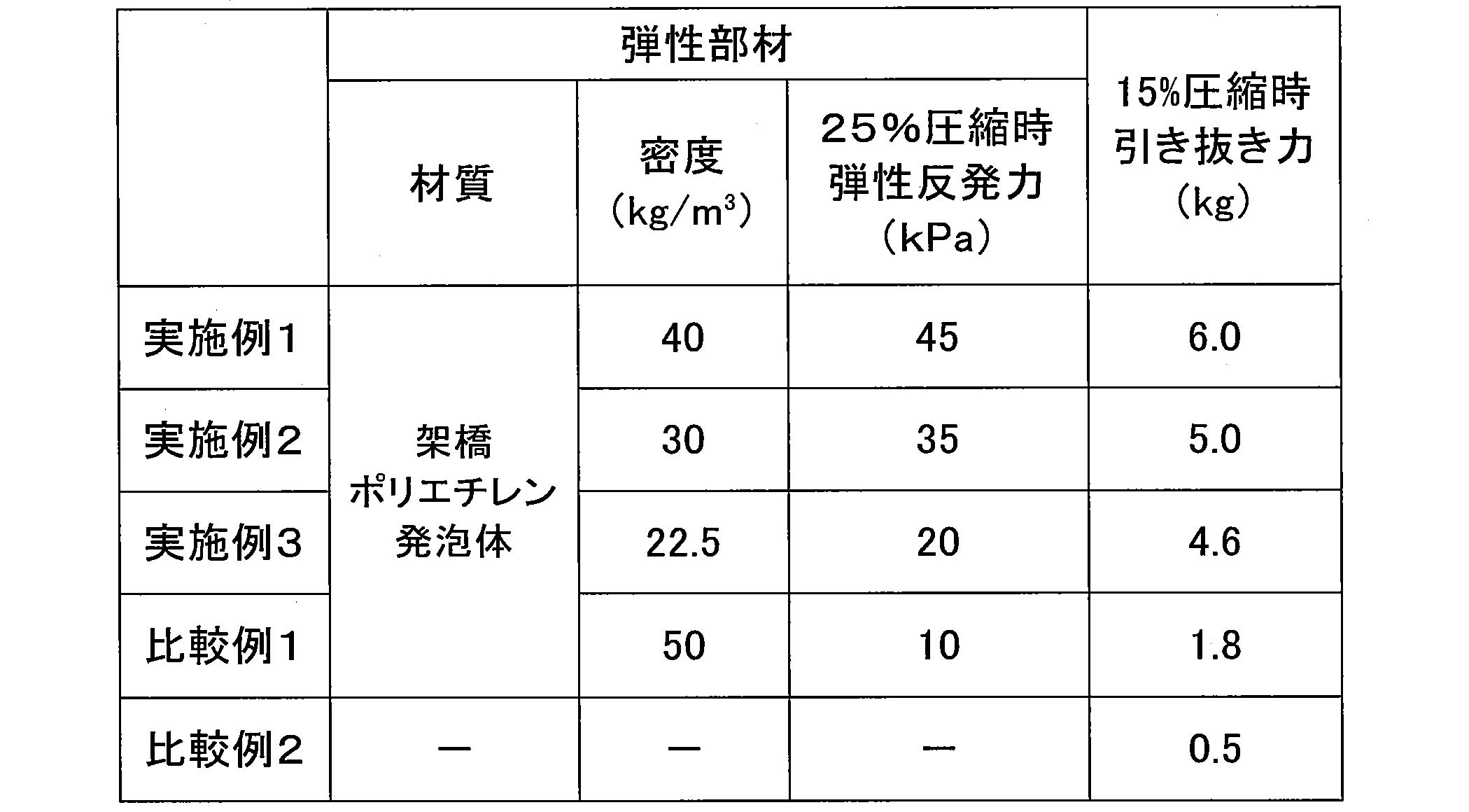
- Example 1 As the elastic member 7, a cross-linked hard polyethylene foam having an elastic repulsion force at 25% compression of 45 kPa and a density of 40 kg / m 3 was used. By placing the elastic member 7 on the cable 11 and closing the trough lid 5, the elastic member 7 was compressed 15% (compressed to a thickness of 80 mm) and the cable 11 was pressed. The trough lid 5 was fixed with a trough lid fixing member (not shown). In this state, the pulling force when pulling out the cable 11 (K in FIG. 18) at the center of the upper stage was obtained by the load measuring device 31.
- Example 2 As the elastic member 7, a cross-linked hard polyethylene foam having an elastic repulsion force at 25% compression of 35 kPa and a density of 30 kg / m 3 was used. By placing the elastic member 7 on the cable 11 and closing the trough lid 5, the elastic member 7 was compressed 15% (compressed to a thickness of 80 mm) and the cable 11 was pressed. The trough lid 5 was fixed with a trough lid fixing member (not shown). In this state, the pulling force when pulling out the cable 11 (K in FIG. 18) at the center of the upper stage was obtained by the load measuring device 31.
- Example 3 As the elastic member 7, a crosslinked soft polyethylene resin foam having an elastic repulsion force at 25% compression of 20 kPa and a density of 22.5 kg / m 3 was used. By placing the elastic member 7 on the cable 11 and closing the trough lid 5, the elastic member 7 was compressed 15% (compressed to a thickness of 80 mm) and the cable 11 was pressed. The trough lid 5 was fixed with a trough lid fixing member (not shown). In this state, the pulling force when pulling out the cable 11 (K in FIG. 18) at the center of the upper stage was obtained by the load measuring device 31.
- Comparative Example 1 which is a resin foam having an extremely low elastic repulsion force at 25% compression of 10 kPa, the pulling force is as low as 1.8 kg, and the effect of improving the pulling force by using the elastic member 7 is insufficient. Met. The reason is considered that the material of Comparative Example 1 is a resin foam made of open cells.
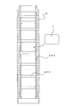
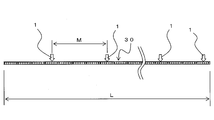
- FIG. 19 shows a state in which the cable antitheft structure 1 (elastic member 7) is arranged at a predetermined pitch (M in the figure) with respect to the trough line (full length L).
- the cable pulling force when the elastic member 7 used in Example 1 is applied is estimated.
- the cable pull-out force when the elastic member 7 used in Example 1 is applied is estimated.
- the soft resin foam of Example 3 was used, the pulling force was not significantly reduced due to an increase in the contact area between the cable and the resin.
- the material of Comparative Example 1 was used as the elastic member, the reduction in elastic repulsion could not be compensated for by increasing the contact area between the cable and the resin foam when the resin foam was pressed. This is probably because the resistance decreased.
- the elastic repulsive force or compression amount of the elastic member is increased, or the installation pitch of the elastic member 7 is reduced, and the arrangement position of the elastic member 7 in the trough line 30 is changed. Increase it. Further, a longer elastic member 7 may be used in the cable theft prevention structure per place. Moreover, even if the cables 11 are bound together, there is a possibility that the frictional force between the cables can be increased.
Landscapes
- Engineering & Computer Science (AREA)
- Mechanical Engineering (AREA)
- Electric Cable Installation (AREA)
- Laying Of Electric Cables Or Lines Outside (AREA)
- Installation Of Indoor Wiring (AREA)
Abstract
Description
以下、図面を参照しながら、本発明の実施形態について説明する。図1は、本発明にかかるケーブル盗難防止構造1を示す分解斜視図であり、図2はケーブル盗難防止構造1を示す組立斜視図である。
次に、第2の実施の形態について説明する。図13(a)は、弾性部材7aを示す図である。なお、以下の実施の形態において、第1の実施形態と同一の機能を奏する構成については、図1から図12と同一の符号を付し、重複する説明を省略する。
次に、第3の実施の形態について説明する。図15は、弾性部材7bを示す図である。弾性部材7bは、弾性部材7aとほぼ同様の構成であるが、弾性体(硬質樹脂発泡体)25a、弾性体(硬質樹脂発泡体)25b、弾性体(軟質樹脂発泡体)25cが積層される点で異なる。
弾性部材7として、25%圧縮時の弾性反発力が45kPaで密度が40kg/m3の架橋硬質ポリエチレン発泡体を用いた。ケーブル11上に弾性部材7を配置してトラフ蓋5を閉めることにより、弾性部材7を15%圧縮(厚さ80mmに圧縮)させて、ケーブル11を押圧した。なお、トラフ蓋5は、図示を省略したトラフ蓋固定部材で固定した。この状態で、上段中央のケーブル11(図18のK)を引き抜く場合の引き抜き力を、荷重測定装置31によって求めた。
弾性部材7として、25%圧縮時の弾性反発力が35kPaで密度が30kg/m3の架橋硬質ポリエチレン発泡体を用いた。ケーブル11上に弾性部材7を配置してトラフ蓋5を閉めることにより、弾性部材7を15%圧縮(厚さ80mmに圧縮)させて、ケーブル11を押圧した。なお、トラフ蓋5は、図示を省略したトラフ蓋固定部材で固定した。この状態で、上段中央のケーブル11(図18のK)を引き抜く場合の引き抜き力を、荷重測定装置31によって求めた。
弾性部材7として、25%圧縮時の弾性反発力が20kPaで密度が22.5kg/m3の架橋軟質ポリエチレン系樹脂発泡体を用いた。ケーブル11上に弾性部材7を配置してトラフ蓋5を閉めることにより、弾性部材7を15%圧縮(厚さ80mmに圧縮)させて、ケーブル11を押圧した。なお、トラフ蓋5は、図示を省略したトラフ蓋固定部材で固定した。この状態で、上段中央のケーブル11(図18のK)を引き抜く場合の引き抜き力を、荷重測定装置31によって求めた。
弾性部材7として、25%圧縮時の弾性反発力が10kPaの特にやわらかい軟質樹脂発泡体で密度が50kg/m3の架橋軟質ポリエチレン発泡体を用いた。ケーブル11上に弾性部材7を配置してトラフ蓋5を閉めることにより、弾性部材7を15%圧縮(厚さ80mmに圧縮)させて、ケーブル11を押圧した。なお、トラフ蓋5は、図示を省略したトラフ蓋固定部材で固定した。この状態で、上段中央のケーブル11(図18のK)を引き抜く場合の引き抜き力を、荷重測定装置31によって求めた。
弾性部材7を用いずに、上段中央のケーブル11(図18のK)を引き抜く場合の引き抜き力を、荷重測定装置31によって求めた。それぞれの結果を表1に示す。
3………トラフ本体
5………トラフ蓋
7、7a、7b………弾性部材
9、9a、9b………トラフ蓋固定部材
11………ケーブル
12………結束部材
13a、13b………嵌合部
15………固定部
17………孔
19………溝
21………係止部
23a、23b、23c、23d………補強リブ
25………弾性体
25a、25b………弾性体(硬質樹脂発泡体)
25c………弾性体(軟質樹脂発泡体)
27、27a………把持部材
29………バックル
30………トラフ線路
31………荷重測定装置
Claims (18)
- トラフ本体の内部に配設されたケーブルと、前記トラフ本体の上部を塞ぐトラフ蓋との間に、弾性部材を配置し、前記トラフ蓋の裏面と前記弾性部材とを接触させ、さらに前記トラフ蓋の裏面で前記弾性部材を押圧することで、前記弾性部材で前記ケーブルを押圧することを特徴とするケーブル盗難防止方法。
- 前記弾性部材は、樹脂発泡体であることを特徴とする請求項1記載のケーブル盗難防止方法。
- 前記樹脂発泡体は2つの端面を有し、前記樹脂発泡体の一方の端面を前記トラフ蓋の裏面と接触させ、前記樹脂発泡体の他方の端面で前記ケーブルを押圧することを特徴とする請求項2に記載のケーブル盗難防止方法。
- 前記トラフ蓋の裏面には、複数の補強リブが形成され、
前記樹脂発泡体を、前記トラフ蓋の裏面の前記補強リブ同士の間に挿入して固定して押圧するか、あるいは前記樹脂発泡体を前記補強リブの先端に接触させて前記樹脂発泡体を押圧することを特徴とする請求項2記載のケーブル盗難防止方法。 - 前記補強リブは、前記トラフ蓋の長手方向に平行な補強リブ及び/または前記トラフ蓋の幅方向に平行な補強リブであることを特徴とする請求項4記載のケーブル盗難防止方法。
- 前記樹脂発泡体は、略直方体であり、前記弾性部材の互いに直交する3辺の長さが互いに異なることを特徴とする請求項2記載のケーブル盗難防止方法。
- 前記トラフ本体の内部には、前記ケーブルが複数本配置され、複数の前記ケーブルを結束部材で結束することを特徴とする請求項2記載のケーブル盗難防止方法。
- 前記樹脂発泡体は、複数層の樹脂発泡体からなる積層構造体であることを特徴とする請求項2記載のケーブル盗難防止方法。
- 前記積層構造体は、硬質樹脂発泡体と軟質樹脂発泡体の少なくともいずれかを含むことを特徴とする請求項8記載のケーブル盗難防止方法。
- 前記積層構造体は、前記軟質樹脂発泡体を、前記硬質樹脂発泡体の表層に積層したもので、前記軟質樹脂発泡体を前記ケーブルと接触させ、前記硬質樹脂発泡体を前記トラフ蓋側と接触させることを特徴とする請求項9記載のケーブル盗難防止方法。
- 前記積層構造体は、接着剤又は粘着剤で各層が接合されることを特徴とする請求項8記載のケーブル盗難防止方法。
- 前記樹脂発泡体は、25%圧縮変形時の弾性反発力が15kPa以上50kPa以下であることを特徴とする請求項2記載のケーブル盗難防止方法。
- 前記弾性部材は、前記トラフ蓋に接着されることを特徴とする請求項1記載のケーブル盗難防止方法。
- 前記弾性部材は、ポリエチレン樹脂、ポリプロピレン樹脂、ポリスチレン樹脂、ポリウレタン樹脂、PVC樹脂、EVA樹脂、EPDMゴム、ニトリロゴム、アクリルゴム、クロロプレンゴムのいずれかの樹脂発泡体またはゴム発泡体からなることを特徴とする請求項1記載のケーブル盗難防止方法。
- トラフ蓋固定部材を用いて、前記トラフ本体に前記トラフ蓋を固定し、前記トラフ蓋固定部材で、前記トラフ蓋を押圧することで、前記弾性部材を前記ケーブルに押圧することを特徴とする請求項1記載のケーブル盗難防止方法。
- トラフ本体と、
前記トラフ本体の上部を塞ぎ、前記トラフ本体に固定されるトラフ蓋と、
前記トラフ本体の内部に配設されるケーブルと、
前記ケーブルを押圧するケーブル押圧部材と、
前記ケーブル押圧部材に押圧力を付与する押圧力付与部材と、
を具備し、
前記ケーブルと前記トラフ蓋との間に、前記ケーブル押圧部材が配置され、前記ケーブル押圧部材は、前記トラフ蓋の裏面と前記ケーブルとに接触する弾性部材であり、前記押圧力付与部材によって、前記トラフ蓋が押圧されることで、前記トラフ蓋を介して、前記ケーブル押圧部材が前記ケーブルへ押圧されることを特徴とするケーブルの盗難防止構造。 - 前記押圧力付与部材は、前記トラフ本体に前記トラフ蓋を固定するトラフ蓋固定部材であり、
前記トラフ蓋固定部材は、固定ボルト、固定バックル、または固定バンドであることを特徴とする請求項16記載のケーブルの盗難防止構造。 - 請求項16記載のケーブルの盗難防止構造が、
複数の前記トラフ本体および前記トラフ蓋が連結されたトラフ線路において、複数箇所に設けられることを特徴とするトラフ線路。
Priority Applications (1)
| Application Number | Priority Date | Filing Date | Title |
|---|---|---|---|
| GB1802747.4A GB2556292B (en) | 2015-08-07 | 2016-07-01 | Trough line having cable theft prevention structures and a method of cable theft prevention in a trough line |
Applications Claiming Priority (2)
| Application Number | Priority Date | Filing Date | Title |
|---|---|---|---|
| JP2015157176A JP5855309B1 (ja) | 2015-08-07 | 2015-08-07 | ケーブル盗難防止方法、ケーブルの盗難防止構造およびトラフ線路 |
| JP2015-157176 | 2015-08-07 |
Publications (1)
| Publication Number | Publication Date |
|---|---|
| WO2017026201A1 true WO2017026201A1 (ja) | 2017-02-16 |
Family
ID=55269191
Family Applications (1)
| Application Number | Title | Priority Date | Filing Date |
|---|---|---|---|
| PCT/JP2016/069702 Ceased WO2017026201A1 (ja) | 2015-08-07 | 2016-07-01 | ケーブル盗難防止方法、ケーブルの盗難防止構造およびトラフ線路 |
Country Status (3)
| Country | Link |
|---|---|
| JP (1) | JP5855309B1 (ja) |
| GB (1) | GB2556292B (ja) |
| WO (1) | WO2017026201A1 (ja) |
Families Citing this family (8)
| Publication number | Priority date | Publication date | Assignee | Title |
|---|---|---|---|---|
| JP7360312B2 (ja) * | 2019-12-11 | 2023-10-12 | 古河電気工業株式会社 | 漏洩同軸ケーブル敷設構造、漏洩同軸ケーブルの敷設方法、漏洩同軸ケーブルを収納するトラフ本体及び漏洩同軸ケーブル敷設構造を用いた通信方法並びに通信システム |
| GB2593891A (en) * | 2020-04-06 | 2021-10-13 | Anderton Concrete Products Ltd | A Cable Trough Assembly |
| JP6935563B1 (ja) * | 2020-09-15 | 2021-09-15 | 古河電気工業株式会社 | 樹脂製のトラフ本体へのグレーチング蓋の取付け構造、トラフ線路、トラフ線路の形成方法及びグレーチング蓋 |
| JP7623176B2 (ja) * | 2021-03-23 | 2025-01-28 | 古河電気工業株式会社 | プロテクタ |
| EP4343994A4 (en) | 2021-05-17 | 2025-05-21 | Furukawa Electric Co., Ltd. | Trough, method for securing a cable to a trough, structure for securing a cable to a trough, structure for securing a trough lid, and metal fitting for securing a trough lid |
| JP7575650B1 (ja) | 2024-03-28 | 2024-10-30 | 株式会社ピー・エス・ディー | 配線盗難防止具およびその施工方法 |
| JP7551956B1 (ja) * | 2024-04-20 | 2024-09-17 | 隼人 高田 | 電線盗難防止方法及び電線盗難防止装置 |
| SE547998C2 (en) * | 2024-05-17 | 2026-01-07 | Jimmy Eriksson | Cable trough with foam glass lid |
Citations (6)
| Publication number | Priority date | Publication date | Assignee | Title |
|---|---|---|---|---|
| JPH0670438U (ja) * | 1993-03-02 | 1994-09-30 | 古河電気工業株式会社 | 防災トラフ |
| JPH0716531U (ja) * | 1993-08-06 | 1995-03-17 | 株式会社土井製作所 | 地中線用ケーブル立上り引込装置 |
| JP2009014147A (ja) * | 2007-07-06 | 2009-01-22 | Kitagawa Ind Co Ltd | クランプ |
| WO2011104863A1 (ja) * | 2010-02-26 | 2011-09-01 | 古河電気工業株式会社 | トラフと蓋との固定構造、トラフと蓋との固定方法 |
| JP2012122323A (ja) * | 2010-11-19 | 2012-06-28 | Furukawa Electric Co Ltd:The | ピット蓋 |
| JP2014011881A (ja) * | 2012-06-29 | 2014-01-20 | Furukawa Electric Co Ltd:The | トラフおよびトラフの連結構造ならびにトラフの連結方法 |
Family Cites Families (5)
| Publication number | Priority date | Publication date | Assignee | Title |
|---|---|---|---|---|
| JP2762196B2 (ja) * | 1992-08-10 | 1998-06-04 | 株式会社フジクラ | 絶縁界面部に保護カバーを設けた電力ケーブル用プレモールド絶縁体 |
| JPH0716531A (ja) * | 1993-07-02 | 1995-01-20 | Toray Ind Inc | 真空吸着式スピナー、これを用いた塗布液の塗布方法および塗膜の現像方法 |
| DE19838951C1 (de) * | 1998-08-27 | 2000-05-04 | Schroff Gmbh | HF-dichte Durchführung |
| JP2001258118A (ja) * | 2000-03-09 | 2001-09-21 | Mitsubishi Electric Corp | ケーブルラック用ケーブル固縛治具 |
| US20110056722A1 (en) * | 2009-02-23 | 2011-03-10 | Panduit Corp. | Wiring Duct Cover With Foam Insert |
-
2015
- 2015-08-07 JP JP2015157176A patent/JP5855309B1/ja active Active
-
2016
- 2016-07-01 GB GB1802747.4A patent/GB2556292B/en active Active
- 2016-07-01 WO PCT/JP2016/069702 patent/WO2017026201A1/ja not_active Ceased
Patent Citations (6)
| Publication number | Priority date | Publication date | Assignee | Title |
|---|---|---|---|---|
| JPH0670438U (ja) * | 1993-03-02 | 1994-09-30 | 古河電気工業株式会社 | 防災トラフ |
| JPH0716531U (ja) * | 1993-08-06 | 1995-03-17 | 株式会社土井製作所 | 地中線用ケーブル立上り引込装置 |
| JP2009014147A (ja) * | 2007-07-06 | 2009-01-22 | Kitagawa Ind Co Ltd | クランプ |
| WO2011104863A1 (ja) * | 2010-02-26 | 2011-09-01 | 古河電気工業株式会社 | トラフと蓋との固定構造、トラフと蓋との固定方法 |
| JP2012122323A (ja) * | 2010-11-19 | 2012-06-28 | Furukawa Electric Co Ltd:The | ピット蓋 |
| JP2014011881A (ja) * | 2012-06-29 | 2014-01-20 | Furukawa Electric Co Ltd:The | トラフおよびトラフの連結構造ならびにトラフの連結方法 |
Also Published As
| Publication number | Publication date |
|---|---|
| GB2556292A8 (en) | 2021-03-03 |
| GB2556292B (en) | 2022-02-23 |
| JP2017038449A (ja) | 2017-02-16 |
| GB201802747D0 (en) | 2018-04-04 |
| GB2556292A (en) | 2018-05-23 |
| JP5855309B1 (ja) | 2016-02-09 |
Similar Documents
| Publication | Publication Date | Title |
|---|---|---|
| JP5855309B1 (ja) | ケーブル盗難防止方法、ケーブルの盗難防止構造およびトラフ線路 | |
| ES2397240T3 (es) | Artículo conformado de material compuesto y proceso para fabricar el mismo | |
| US5913480A (en) | Redetachable, self-adhesive fastening device | |
| KR20190092625A (ko) | 분리가능한 접착 스트립 | |
| WO2008130091A1 (en) | Un-vulcanized synthetic rubber sheets-waterproof material of self-adhesion type and construction method using the same | |
| JP2015214134A (ja) | 積層シート | |
| US12134890B2 (en) | Water drainage system | |
| KR20120130279A (ko) | 롤 안정화 양면 감압성 접착 테이프 조립체 | |
| WO2024200428A1 (en) | Roof system with adhered construction boards | |
| JP2010215900A (ja) | 粘着シート及びその製造方法 | |
| JP5431668B2 (ja) | 伸長性粘着シート | |
| JP5902582B2 (ja) | 結束テープ | |
| WO1997003315A1 (en) | Pressure sensitive adhesive closure system for foam insulation | |
| JP2013087817A (ja) | ケーブル支持金具 | |
| KR101938751B1 (ko) | 재작업성이 우수한 신장가능한 폼 점착테이프 및 이의 제작방법 | |
| JP6069557B2 (ja) | 結束テープ | |
| JP2010177356A (ja) | 太陽電池モジュール用止水テープ | |
| JP6719921B2 (ja) | 取付装置および取付装置の使用方法 | |
| JP3345333B2 (ja) | 粘着性クッションシート | |
| JP5430072B2 (ja) | 剥離可能な粘着テープ | |
| US11699865B2 (en) | Removable electrical connectors and devices | |
| JP3557249B2 (ja) | 床パネル | |
| KR101975283B1 (ko) | 중공탄성체를 이용한 연신가능한 쿠션 테이프 및 그 제조방법 | |
| JP3111439B2 (ja) | 成形物接着固定用部材 | |
| JPH0243854Y2 (ja) |
Legal Events
| Date | Code | Title | Description |
|---|---|---|---|
| 121 | Ep: the epo has been informed by wipo that ep was designated in this application |
Ref document number: 16834898 Country of ref document: EP Kind code of ref document: A1 |
|
| NENP | Non-entry into the national phase |
Ref country code: DE |
|
| ENP | Entry into the national phase |
Ref document number: 201802747 Country of ref document: GB Kind code of ref document: A Free format text: PCT FILING DATE = 20160701 |
|
| 122 | Ep: pct application non-entry in european phase |
Ref document number: 16834898 Country of ref document: EP Kind code of ref document: A1 |