WO2017026164A1 - コネクタ - Google Patents
コネクタ Download PDFInfo
- Publication number
- WO2017026164A1 WO2017026164A1 PCT/JP2016/066351 JP2016066351W WO2017026164A1 WO 2017026164 A1 WO2017026164 A1 WO 2017026164A1 JP 2016066351 W JP2016066351 W JP 2016066351W WO 2017026164 A1 WO2017026164 A1 WO 2017026164A1
- Authority
- WO
- WIPO (PCT)
- Prior art keywords
- connector
- lock
- angle
- housing
- rear direction
- Prior art date
- Legal status (The legal status is an assumption and is not a legal conclusion. Google has not performed a legal analysis and makes no representation as to the accuracy of the status listed.)
- Ceased
Links
Images










Classifications
-
- H—ELECTRICITY
- H01—ELECTRIC ELEMENTS
- H01R—ELECTRICALLY-CONDUCTIVE CONNECTIONS; STRUCTURAL ASSOCIATIONS OF A PLURALITY OF MUTUALLY-INSULATED ELECTRICAL CONNECTING ELEMENTS; COUPLING DEVICES; CURRENT COLLECTORS
- H01R13/00—Details of coupling devices of the kinds covered by groups H01R12/70 or H01R24/00 - H01R33/00
- H01R13/62—Means for facilitating engagement or disengagement of coupling parts or for holding them in engagement
- H01R13/639—Additional means for holding or locking coupling parts together, after engagement, e.g. separate keylock, retainer strap
-
- H—ELECTRICITY
- H01—ELECTRIC ELEMENTS
- H01R—ELECTRICALLY-CONDUCTIVE CONNECTIONS; STRUCTURAL ASSOCIATIONS OF A PLURALITY OF MUTUALLY-INSULATED ELECTRICAL CONNECTING ELEMENTS; COUPLING DEVICES; CURRENT COLLECTORS
- H01R12/00—Structural associations of a plurality of mutually-insulated electrical connecting elements, specially adapted for printed circuits, e.g. printed circuit boards [PCB], flat or ribbon cables, or like generally planar structures, e.g. terminal strips, terminal blocks; Coupling devices specially adapted for printed circuits, flat or ribbon cables, or like generally planar structures; Terminals specially adapted for contact with, or insertion into, printed circuits, flat or ribbon cables, or like generally planar structures
- H01R12/70—Coupling devices
- H01R12/77—Coupling devices for flexible printed circuits, flat or ribbon cables or like structures
-
- H—ELECTRICITY
- H01—ELECTRIC ELEMENTS
- H01R—ELECTRICALLY-CONDUCTIVE CONNECTIONS; STRUCTURAL ASSOCIATIONS OF A PLURALITY OF MUTUALLY-INSULATED ELECTRICAL CONNECTING ELEMENTS; COUPLING DEVICES; CURRENT COLLECTORS
- H01R12/00—Structural associations of a plurality of mutually-insulated electrical connecting elements, specially adapted for printed circuits, e.g. printed circuit boards [PCB], flat or ribbon cables, or like generally planar structures, e.g. terminal strips, terminal blocks; Coupling devices specially adapted for printed circuits, flat or ribbon cables, or like generally planar structures; Terminals specially adapted for contact with, or insertion into, printed circuits, flat or ribbon cables, or like generally planar structures
- H01R12/70—Coupling devices
- H01R12/82—Coupling devices connected with low or zero insertion force
- H01R12/85—Coupling devices connected with low or zero insertion force contact pressure producing means, contacts activated after insertion of printed circuits or like structures
- H01R12/87—Coupling devices connected with low or zero insertion force contact pressure producing means, contacts activated after insertion of printed circuits or like structures acting automatically by insertion of rigid printed or like structures
Definitions
- the present invention relates to a connector that can be connected to an object such as FFC (Flexible Flat Cable) or FPC (Flexible Printed Circuits).
- FFC Flexible Flat Cable
- FPC Flexible Printed Circuits
- Patent Document 1 This type of connector is disclosed in Patent Document 1, for example.
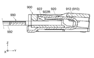
- the electrical connector (connector) 900 disclosed in Patent Document 1 can be connected to a signal transmission medium (object) 990 such as an FPC along the front-rear direction (Y direction).
- the connector 900 includes an insulating housing (housing) 910 and a lock member 920 held by the housing 910.
- the housing 910 is provided with an operation cover 912 for operating the lock member 920.
- the lock member 920 has a locking lock portion (lock portion) 922.
- the lock portion 922 has a rear side portion 922R.
- An engagement positioning portion (locked hole) 992 is formed in the object 990.
- the lock portion 922 is positioned inside the locked hole 992.
- the rear portion 922R of the lock portion 922 faces the inner wall of the locked hole 992 in the Y direction, so that the object 990 is prevented from being removed from the connector 900.
- the rear side portion 922R of the lock portion 922 is a vertical plane orthogonal to the Y direction.
- the object 990 is reliably prevented from being unintentionally removed from the connector 900 due to an impact or the like.
- the object 990 cannot be removed from the connector 900 simply by pulling the object 990 in the ⁇ Y direction.
- the operation cover 912 needs to be operated. Therefore, the connector 900 needs to be installed so that the operation cover 912 can be operated.
- the connector 900 cannot be installed in a narrow space covered above. That is, the place where the connector 900 can be installed is limited.
- an object of the present invention is to provide a connector that can be connected to an object such as FFC or FPC, and that can prevent unintentional removal of the object and that can be removed simply by pulling the object. .
- the connector includes a housing, a plurality of contacts, and a lock member.
- the housing holds the contacts side by side in a pitch direction perpendicular to the front-rear direction.
- the housing holds the lock member.
- the lock member has a lock portion that locks the locked portion of the object.
- the lock portion has a front side portion and a rear side portion.
- the front side portion is located on the front side of the lock portion in the front-rear direction.
- the rear side portion is located on the rear side of the lock portion in the front-rear direction.
- the front side portion includes a front predetermined point.
- the rear side portion includes a rear predetermined point.
- the front predetermined point and the rear predetermined point are located at the same position in the vertical direction perpendicular to both the front-rear direction and the pitch direction.
- a tangent at the predetermined point on the front side of the lock portion extends downward and rearward in a vertical plane perpendicular to the pitch direction and intersects the front-rear direction at a first angle. is doing.
- a tangent at the rear predetermined point of the lock portion extends downward and forward in the vertical plane and intersects the front-rear direction at a second angle.
- Each of the first angle and the second angle is greater than 0 ° and smaller than 90 °.
- the second angle is larger than the first angle.
- the connector includes a housing, a plurality of contacts, and a lock member.
- the housing holds the contacts side by side in a pitch direction perpendicular to the front-rear direction.
- the housing holds the lock member.
- the lock member has a lock portion that locks the locked portion of the object.
- the lock portion has a front side portion and a rear side portion. The front side portion is located on the front side of the lock portion in the front-rear direction. The rear side portion is located on the rear side of the lock portion in the front-rear direction.
- Each of the front side portion and the rear side portion is a plane that obliquely intersects with the front-rear direction and obliquely intersects with the up-down direction perpendicular to both the front-rear direction and the pitch direction.
- the front side portion When the object is not inserted into the connector, the front side portion extends downward and rearward and intersects the front-rear direction at a first angle.
- the rear side portion When the object is not inserted into the connector, the rear side portion extends downward and forward and intersects the front-rear direction at a second angle.
- Each of the first angle and the second angle is greater than 0 ° and smaller than 90 °. The second angle is larger than the first angle.
- the tangent of the rear side of the lock portion intersects the front-rear direction at a second angle that is larger than the first angle at which the tangent of the front side of the lock portion intersects the front-rear direction.
- the front-back direction is the direction in which the object is inserted and removed.
- the operator needs to apply a removal force larger than the insertion force necessary to insert the object into the connector.
- the second angle is smaller than 90 °. For this reason, the lock part is unlocked by pulling the object with the removal force. In other words, the object can be removed from the connector simply by pulling the object.
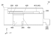
- FIG. 4 is an exploded perspective view showing the connector of FIG. 3. It is a perspective view which shows the housing of the connector of FIG. It is a rear view which shows the one side in the pitch direction of the housing of FIG. It is a perspective view which shows the contact of the connector of FIG.
- FIG. 4 is another perspective view showing the connector of FIG. 3.
- FIG. 4 is still another perspective view showing the connector of FIG. 3.
- FIG. 4 is a top view showing the vicinity of one side portion in the pitch direction of the connector of FIG. 3.
- FIG. 4 is a side view showing the connector of FIG. 3.
- FIG. 4 is a rear view showing the vicinity of one side portion in the pitch direction of the connector of FIG. 3.
- FIG. 4 is a front view showing the connector of FIG. 3.
- FIG. 19 is a cross-sectional view showing the connector of FIG. 18 along the line XIX-XIX. The vicinity of the lock portion of the lock member (portion surrounded by a one-dot chain line) is enlarged and drawn.
- FIG. 19 is a cross-sectional view showing the connector of FIG. 18 along the line XX-XX. The vicinity of the lock portion of the lock member (portion surrounded by a one-dot chain line) is enlarged and drawn.
- FIG. 4 is a partially cutaway perspective sectional view of the connector of FIG. 3 and an object. The lower end of the upper plate portion of the housing is drawn with a broken line (virtual line).
- the object has started to be inserted into the connector but is not connected to the connector. It is a perspective view which shows the connector and target object of FIG. The object is connected to the connector. It is sectional drawing which shows the vicinity of the lock part of FIG. 20 except a contact. The tip of the object when the object is inserted into the connector is drawn with a one-dot chain line, and the locked portion of the object when the object is removed from the connector is drawn with a two-dot chain line. It is sectional drawing which shows the modification of the lock
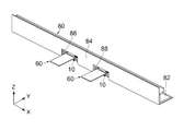
- each of the connectors 10 according to the embodiment of the present invention is used by being attached to a structure 80.
- the structure 80 according to the present embodiment is a power supply unit of an LED (Light-Emitting-Diode) backlight.
- the structure 80 according to the present embodiment includes a fixed object (circuit board) 82 and a wall portion 84.
- the circuit board 82 is located inside the structure 80.
- the wall portion 84 separates the circuit board 82 from the outside of the structure 80.
- each of the connectors 10 is mounted and fixed on the circuit board 82 in the vertical direction.
- the vertical direction is the Z direction.
- the upper direction is the + Z direction, and the lower direction is the -Z direction.
- each of the connectors 10 is installed inside the structure 80.
- Two connectors 10 are installed in the illustrated structure 80.
- the present invention is not limited to this.
- the type and use of the structure 80 are not particularly limited.
- the number of connectors 10 installed in the structure 80 may be one or three or more.
- each connector 10 in the front-rear direction is located in the vicinity of the corresponding window 88 in the front-rear direction.
- the front end of each connector 10 in the front-rear direction is located inside the corresponding window 88 in a plane orthogonal to the front-rear direction.
- the front-rear direction is the Y direction.
- the front is the ⁇ Y direction, and the rear is the + Y direction.
- the front end of the connector 10 is the ⁇ Y side end.
- the plane orthogonal to the front-rear direction is the XZ plane.
- the connector 10 can be connected to a flat plate-like FPC (object) 60.
- the object 60 has an insertion portion 62.
- the inserted portion 62 of the object 60 can be inserted into the connector 10 from the front of the connector 10 along the insertion direction.
- the inserted portion 62 of the object 60 can be removed from the connector 10 along the removal direction.
- the insertion direction is the + Y direction
- the removal direction is the -Y direction.
- the inserted portion 62 is provided with a plurality of terminals 64 and two recesses 66.
- the terminals 64 are arranged in the pitch direction on the upper surface of the inserted portion 62.
- the upper surface of the insertion portion 62 is a + Z side surface.
- the pitch direction is the X direction.
- the recesses 66 are respectively formed on both sides in the X direction of the inserted portion 62.
- Each of the recesses 66 is recessed inward in the X direction.
- a locked portion 68 is formed in each of the recesses 66.
- the target object 60 has the two locked parts 68.
- Locked portion 68 according to the present embodiment is an inner wall located on the + Y side of recess 66.
- the present invention is not limited to this.
- the locked portion 68 may be an inner wall of a hole that penetrates the inserted portion 62 in the Z direction, and may be an inner wall located on the + Y side of the hole.
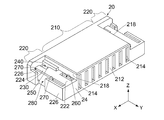
- the connector 10 includes a housing 20, a plurality of contacts 30, and two lock members 40.
- the housing 20 is made of an insulator.
- Each of the contacts 30 is made of a conductor.
- Each of the lock members 40 is made of metal.
- the connector 10 is formed with a receiving portion 12 for receiving the inserted portion 62 of the object 60 (see FIG. 21).
- the receiving portion 12 according to the present embodiment is a space located inside the housing 20.
- the receiving part 12 according to the present embodiment opens forward.
- the housing 20 has one main part 210 and two side parts 220.
- the main portion 210 is located at an intermediate portion in the X direction of the housing 20.
- the side portions 220 are respectively located on both sides of the housing 20 in the X direction.
- Side surfaces 218 are formed on both sides of the main portion 210 in the X direction.
- the side portions 220 correspond to the side surfaces 218, respectively.
- Each of the side portions 220 is located outside the corresponding side surface 218 in the X direction.
- the housing 20 has a mirror-symmetric shape with respect to the YZ plane. Accordingly, the two side portions 220 have a mirror-symmetric shape with respect to the YZ plane.
- the housing 20 has a rear surface (rear end) 24 in the front-rear direction. In the present embodiment, the rear end 24 is configured by a rear end surface (+ Y side end surface) of the main portion 210 and the side portion 220.
- a rear wall 212 is formed at the rear part (the + Y side portion) of the main part 210.
- the receiving portion 12 is located in front of the rear wall 212 in the Y direction, and extends to the inside of the side portion 220 beyond the side surface 218 of the main portion 210 in the X direction. Yes.
- a plurality of holding portions 214 are formed on the rear wall 212.
- the holding parts 214 are arranged in the X direction. Referring to FIG. 19, each of the holding portions 214 extends through the rear wall 212 in the Y direction to the receiving portion 12.
- each of the side portions 220 has an upper plate portion 222, an inner wall surface 224, and two outer walls 226.
- the upper plate portion 222 is a flat plate portion.
- the upper plate portion 222 is located between the vicinity of the front end of the side portion 220 and the rear end 24 in the Y direction, and is located on the receiving portion 12 in the Z direction.
- the inner wall surface 224 is a vertical plane orthogonal to the X direction.
- the inner wall surface 224 is provided at the outer end of the upper plate portion 222 in the X direction.
- One of the outer walls 226 is formed near the front end of the side portion 220.
- the remaining one of the outer walls 226 is formed in the rear part of the side part 220.
- Each of the outer walls 226 is located outside the inner wall surface 224 in the X direction and extends in parallel with the inner wall surface 224.
- Each of the outer walls 226 is connected to the inner wall surface 224 at the lower end (end on the ⁇ Z side).
- each of the side portions 220 includes a restriction portion 230, a passage path 240, a guide portion 250, a press-fit portion 260, two insertion portions 270, and a positioning portion 280.
- the housing 20 includes a restriction portion 230, a passage path 240, a guide portion 250, a press-fit portion 260, an insertion portion 270, and a positioning portion 280, which are formed on the two side portions 220, respectively.
- the regulating part 230 is composed of an upper plate part 222.
- the upper surface of the restricting portion 230 extends to the rear end 24 of the housing 20 on the XY plane, that is, on the horizontal plane orthogonal to the Z direction. For this reason, when producing the housing 20 using a metal mold
- FIG. 1 A metal mold
- the passage 240 is a hole located in the vicinity of the front end of the upper plate portion 222.
- the passage path 240 extends from the outside of the housing 20 to the receiving portion 12.
- the guide part 250 is a protrusion having a rectangular parallelepiped shape.
- the guide part 250 is located near the front end of the upper plate part 222 and protrudes upward while extending in the Y direction along the side surface 218.
- the upper end (+ Z side end) of the guide part 250 is located above the passage 240 in the Z direction.
- the passage path 240 is located between the restricting portion 230 and the guide portion 250 in the X direction. In other words, the passage 240 is adjacent to each of the restricting portion 230 and the guide portion 250 in the X direction.
- the press-fit portion 260 is a hole located at the rear portion of the upper plate portion 222.
- the press-fit portion 260 extends downward ( ⁇ Z direction) from the upper plate portion 222 and penetrates the side portion 220.
- the press-fit portion 260 extends in parallel with the YZ plane as a whole.
- each of the insertion portions 270 is a groove formed between the inner wall surface 224 and the outer wall 226.
- Each of the insertion portions 270 extends parallel to the YZ plane as a whole.
- the positioning part 280 is a space located between the outer wall 226 located on the ⁇ Y side of the side part 220 and the outer wall 226 located on the + Y side of the side part 220.
- Each of the positioning portion 280 and the insertion portion 270 is aligned in the Y direction. Specifically, the positioning part 280 is located between the two insertion parts 270 in the Y direction.
- the press-fit portion 260 is located near the end on the inner side in the X direction of the side portion 220.
- Each of the insertion portion 270 and the positioning portion 280 is located near the end of the side portion 220 on the outer side in the X direction.
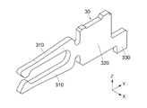
- each of the contacts 30 has the same shape. As shown in FIG. 7, each of the contacts 30 has two connection portions 310, a held portion 320, and a fixed portion 330. Each of the connection portions 310 extends forward from the held portion 320. A press-fit projection is formed on the held portion 320. The fixed part 330 extends downward from the held part 320 as a whole.
- each of the contacts 30 is press-fitted into the housing 20 from the rear. Specifically, the held portions 320 of the contacts 30 are press-fitted and held in the holding portions 214, respectively. Thereby, the housing 20 holds the contacts 30 so as to be arranged in the X direction. Referring to FIG. 18, each of the front ends of the connecting portion 310 protrudes into the receiving portion 12. Referring to FIG. 13, the fixed portion 330 is fixed to the circuit board 82 (see FIG. 1) by soldering or the like when the connector 10 is used.
- the two lock members 40 have mirror-symmetric shapes with respect to the YZ plane.
- Each of the lock members 40 according to the present embodiment is formed of a single metal plate that is punched and bent. Thereby, the lock member 40 having necessary strength and spring property can be formed relatively easily.
- the present invention is not limited to this.
- each of the lock members 40 may be formed by combining a plurality of metal plates.
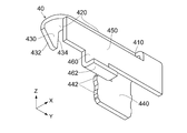
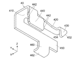
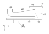
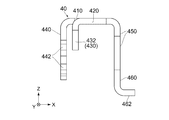
- each of the lock members 40 includes a support portion 410, a spring portion 420, a lock portion 430, a press-fit portion 440, a connection portion 450, and a stop portion 460. And have.
- each of the support portion 410 and the spring portion 420 has a flat plate shape orthogonal to the Z direction
- each of the lock portion 430, the press-fit portion 440, and the connecting portion 450 is orthogonal to the X direction. It has a flat plate shape.
- the present invention is not limited to this.
- each of the support part 410 and the spring part 420 may be slightly oblique to the Z direction.
- each of the lock portion 430, the press-fit portion 440, and the connecting portion 450 may be slightly oblique to the X direction.
- each of the support portion 410 and the spring portion 420 only needs to intersect the Z direction
- each of the lock portion 430, the press-fit portion 440, and the connection portion 450 only needs to intersect the X direction.
- the support portion 410 supports the spring portion 420 in a cantilever shape so as to be elastically deformable.
- the lock part 430 is provided at the free end of the spring part 420.
- the lock part 430 can move in the Z direction by elastic deformation of the spring part 420.
- Each of the press-fit portion 440 and the connecting portion 450 is connected to the support portion 410 and extends downward.
- the press-fit portion 440 and the connecting portion 450 according to the present embodiment are connected to both sides of the support portion 410 in the X direction.
- the stop portion 460 extends downward from the lower end of the front portion (-Y side portion) of the connecting portion 450.
- the connecting part 450 connects the support part 410 and the stopper part 460 to each other.
- the stopper 460 has a fixed part 462.
- the fixed portion 462 is located at the lower end of the stopper portion 460 and projects outward in the X direction.
- the lock member 40 is attached to the side portion 220 of the housing 20 from above. Specifically, as shown in FIGS. 8 to 10, a plurality of press-fitting protrusions 442 are formed on each of the + Y side edge surface and the ⁇ Y side edge surface of the press-fit portion 440. Referring to FIGS. 13 and 15, the respective press-fit portions 440 of the lock member 40 are press-fit from above into the press-fit portions 260 of the corresponding side portions 220 of the housing 20 and extend downward. Thereby, the housing 20 holds the lock member 40. According to the present embodiment, each of the press-fit protrusions 442 (see FIG. 10) of the press-fit portion 440 protrudes in the Y direction.
- the present invention is not limited to this.
- the press-fit protrusion 442 may protrude in any direction orthogonal to the Z direction.
- the press-fitting protrusion 442 may be provided only on one of the + Y side edge surface and the ⁇ Y side edge surface of the press-fit portion 440.
- each connecting portion 450 of the lock member 40 is inserted into the insertion portion 270 of the corresponding side portion 220 of the housing 20 from above.
- Each connecting portion 450 of the locking member 40 is located at least partially within the insertion portion 270 of the corresponding side portion 220.
- Each of the stop portions 460 is located at least partially within the corresponding positioning portion 280. Thereby, each front end and rear end of the positioning portion 280 regulate movement of the corresponding stopper portion 460 in the Y direction.
- the front end of the positioning part 280 is the rear end of the outer wall 226 located on the ⁇ Y side of the side part 220, and the rear end of the positioning part 280 is the front end of the outer wall 226 located on the + Y side of the side part 220.
- the lower end of the press-fit portion 440 is located above the lower end (fixed portion 462) of the stopper portion 460 in the Z direction. Therefore, referring to FIG. 13, when the lock member 40 is attached to the housing 20 from above, first, the fixed portion 462 of the stopper 460 is inserted into the positioning portion 280. As a result, the lock member 40 is roughly positioned in the XY plane. Next, the press-fit portion 440 is press-fitted into the press-fit portion 260, and the connecting portion 450 is inserted into the insertion portion 270. As a result, the lock member 40 is attached to the housing 20 and the position of the lock member 40 in the XY plane is fixed. As understood from the above description, the lock member 40 according to the present embodiment has a structure that allows itself to be easily positioned in the XY plane.
- each of the fixed portions 462 of the stopper 460 is fixed to the circuit board 82 (see FIG. 1) by soldering or the like when the connector 10 is used.
- Two fixed parts 462 are fixed to the circuit board 82 in the vicinity of the front end of the connector 10, and each fixed part 330 of the plurality of contacts 30 is fixed to the circuit board 82 at the rear end of the connector 10. Thereby, the connector 10 is firmly fixed to the circuit board 82.
- the support portion 410 of the lock member 40 is firmly held by the two portions of the press-fit portion 440 and the stopper portion 460 when the connector 10 is used.
- the support portion 410 is provided with two portions that respectively prevent the support portion 410 from moving in the Z direction.
- the two parts are a press-fit portion 440 connected to the inside of the support portion 410 in the X direction, and a stop indirectly connected to the outside of the support portion 410 in the X direction via a connecting portion 450. Part 460.
- Each of the two portions that prevent the support portion 410 from moving in the Z direction may be connected to any portion of the support portion 410.
- the stop portion 460 may be directly connected to the rear end of the support portion 410. Sites other than the press-fit portion 440 and the stopper portion 460 may prevent the support portion 410 from moving in the Z direction.
- the lock member 40 may have another press-fit portion connected to the rear end of the support portion 410.
- the lock member 40 may have only one portion that prevents the support portion 410 from moving in the Z direction.
- the lock member 40 may not have the connecting part 450 and the stopper part 460.
- each of the support portions 410 is disposed on the corresponding restriction portion 230 of the housing 20.
- the spring part 420 extends forward from the support part 410.
- the lock part 430 is provided at the front end of the spring part 420.
- the spring portion 420 according to the present embodiment has a side portion in the X direction, and the lock portion 430 according to the present embodiment is downward from one side portion (inward in the X direction) of the spring portion 420 in the X direction. It extends to.
- the spring portion 420 can have a long spring length.
- the spring part 420 can have a longer spring length by extending the front end of the spring part 420 further inward in the X direction.
- the size of the spring portion 420 in the X direction decreases as the distance from the front of the spring portion 420 decreases.
- the lock member 40 has a structure in which the lock portion 430 can easily move in the Z direction.
- the lock part 430 is located between the press-fit part 440 and the connecting part 450 in the X direction.
- the boundary 422 between the spring portion 420 and the support portion 410 is located between the press-fit portion 440 and the connecting portion 450 in the X direction.
- each of the lock portions 430 is guided by the corresponding guide portion 250 and smoothly inserted into the corresponding passageway 240. .
- each of the lock portions 430 protrudes into the receiving portion 12 through the corresponding passage 240 (see FIG. 18).
- the lock unit 430 moves the inserted part 62 forward of the locked part 68 when the inserted part 62 of the object 60 is inserted into the receiving part 12 and the object 60 is connected to the connector 10. (See FIG. 22).
- each of the lock parts 430 locks the corresponding locked part 68.
- the lock portion 430 has a front side portion 432 and a rear side portion 434.
- the front side portion 432 is located on the front side ( ⁇ Y side) in the Y direction of the lock portion 430.
- the rear side part 434 is located on the rear side (+ Y side) in the Y direction of the lock part 430.
- Each of the front side portion 432 and the rear side portion 434 is a plane that obliquely crosses both the Y direction and the Z direction. More specifically, each of the front side portion 432 and the rear side portion 434 is an edge surface of the lock portion 430.
- the front side portion 432 extends downward and rearward and intersects the Y direction at the first angle ⁇ 1.
- the rear side portion 434 extends downward and forward and intersects the Y direction at the second angle ⁇ 2.
- Each of the first angle ⁇ 1 and the second angle ⁇ 2 is larger than 0 ° and smaller than 90 °.
- the second angle ⁇ 2 is larger than the first angle ⁇ 1.
- each rear side part 434 of the lock part 430 is positioned in front of the corresponding locked part 68 of the object 60.
- the intersection angle between the rear side portion 434 and the Y direction is larger than the intersection angle between the front side portion 432 and the Y direction.
- the tangent line of the rear side portion 434 intersects the Y direction at a larger angle than the tangent line of the front side portion 432.
- each of the locked parts 68 comes into contact with the corresponding rear side part 434.
- each of the lock portions 430 stops the corresponding forward movement of the locked portion 68 without moving upward.
- each of the lock portions 430 continues to lock the corresponding locked portion 68.
- the extraction force Fr can be set to have a strength greater than the strength of the force generated by a normal impact by adjusting the intersection angle between the rear side portion 434 and the Y direction and the spring property of the spring portion 420.
- each of the locked portions 68 abuts the corresponding rear side portion 434.
- the intersection angle between the rear side portion 434 and the Y direction is smaller than 90 °.
- the tangent line of the rear side portion 434 intersects the Y direction at an angle smaller than 90 °. Therefore, when the object 60 is pulled forward with the removal force Fr, each of the lock portions 430 moves upward. At this time, each of the lock portions 430 moves upward while being restricted from moving inward in the X direction by the corresponding guide portion 250. In other words, the extraction force Fr moves each of the lock portions 430 substantially only upward.
- each of the lock portions 430 moved upward is slid on the upper surface of the insertion portion 62 and then positioned behind the insertion portion 62. As a result, the object 60 is removed from the connector 10.
- each of the regulating portions 230 is located above the corresponding locked portion 68 in the Z direction when the object 60 is inserted into the connector 10. The movement in the Z direction is restricted.
- Each of the restricting portions 230 restricts the movement of the corresponding locked portion 68 in the Z direction even when the object 60 is removed from the connector 10. If the locked portion 68 is in contact with the rear side portion 434 while being tilted with respect to both the Y direction and the Z direction, the lock portion 430 does not move upward and cannot be unlocked. However, since the restricting portion 230 prevents the locked portion 68 from being inclined with respect to both the Y direction and the Z direction, the above-described situation does not occur.
- each of the restricting portions 230 has sufficient strength and can more reliably restrict the movement of the corresponding locked portion 68 in the Z direction.
- each of the spring portions 420 is located on the corresponding restricting portion 230. That is, each of the spring portions 420 is positioned slightly upward from the corresponding restricting portion 230. For this reason, even if each of the lock
- each of the spring portions 420 is located on the corresponding restricting portion 230. For this reason, each downward movement of the lock part 430 can be controlled more reliably.
- the spring part 420 may be located at least partially on the restriction part 230 and extend in the Y direction.
- the installation place of the connector 10 is not limited. Further, the connector 10 does not need to include a member or a part for operating the lock member 40.
- the connector 10A according to the modified example has the same structure as the connector 10 (see FIG. 3) except that the lock member 40A is slightly different from the lock member 40 (see FIG. 3).
- 40 A of lock members have the same structure as the structure of the lock member 40 except having the lock part 430A which has a shape different from the shape of the lock part 430 (refer FIG. 23).
- the lock portion 430A has a front side portion 432A and a rear side portion 434A.
- Each of the front side portion 432A and the rear side portion 434A has an arc shape in the YZ plane.
- the front side portion 432A and the rear side portion 434A are connected to each other at the lower end 438 of the lock portion 430A.
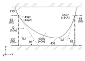
- the front side portion 432A includes a front predetermined point 432P.
- the rear side portion 434A includes a rear predetermined point 434P.
- the first tangent line (tangent line) TL1 at the front predetermined point 432P extends downward and rearward in a vertical plane (YZ plane) orthogonal to the X direction. It intersects at one angle ⁇ 1.
- the second tangent (tangent) TL2 at the rear predetermined point 434P extends downward and forward in the YZ plane and intersects the Y direction at the second angle ⁇ 2.
- Each of the first angle ⁇ 1 and the second angle ⁇ 2 is larger than 0 ° and smaller than 90 °.
- the second angle ⁇ 2 is larger than the first angle ⁇ 1.
- Each of the front predetermined point 432P and the rear predetermined point 434P is located at the same position as the position of the upper surface of the object 60 in the Z direction. For this reason, when the insertion of the object 60 into the connector 10A is started, the tip (+ Y side end) of the inserted portion 62 abuts the front predetermined point 432P. Further, when the object 60 connected to the connector 10A is started to be removed from the connector 10, the locked portion 68 hits the rear predetermined point 434P. With this structure, unintentional removal of the object 60 from the connector 10A can be prevented and the object 60 can be extracted from the connector 10A simply by pulling the object 60, as in the present embodiment.
- the positions of the front predetermined point 432P and the rear predetermined point 434P in the Z direction differ depending on the size of the object 60 in the Z direction.
- the arc of the front side portion 432A is generally gently curved as compared with the arc of the rear side portion 434A.
- the front side portion 432A may be a part of a portion located on the front side of the lock portion 430A.
- the rear side portion 434A may be a part of a portion located on the rear side of the lock portion 430A.
- each of the front side portion 432A and the rear side portion 434A may not have an arc shape.
- the front side portion 432A may be a plane that obliquely intersects both the Y direction and the Z direction. In this case, when the object 60 is not inserted into the connector 10A, the front side portion 432A has a second angle ⁇ 2 at the rear predetermined point 434P (a point located between the upper end and the lower end of the front side portion 432A in the Z direction).
- the rear side portion 434A may be a plane that obliquely intersects both the Y direction and the Z direction. In this case, when the object 60 is not inserted into the connector 10A, the rear side portion 434A has a first angle at the front predetermined point 432P (a point located between the upper end and the lower end of the rear side portion 434A in the Z direction). It only needs to intersect the Y direction at a second angle ⁇ 2 larger than ⁇ 1.
- the present invention can be applied to a connector into which an object having a shape other than a flat plate shape can be inserted.
- the connector may include another member in addition to the housing, the contact, and the lock member.
- the contact may have any shape.
- the lock members may have the same shape. Further, the number of locking members may be one, or may be three or more.
- the connector includes two mirror-symmetric locking members as in the present embodiment.
- the housing and the lock member can be variously modified.
- the housing may not have a guide part.
- the passage may be a gap formed between the side surface of the main part and the restriction part on the side part.
- the spring portion of the lock member may extend from the front to the rear of the connector.
- the restricting portion may extend to the front end of the housing.
- Each of the insertion portion and the positioning portion of the housing may be a hole that penetrates the side portion in the Z direction.
- the present invention is based on Japanese Patent Application No. 2015-156974 filed with the Japan Patent Office on August 7, 2015, the contents of which are hereby incorporated by reference.
Landscapes
- Details Of Connecting Devices For Male And Female Coupling (AREA)
- Coupling Device And Connection With Printed Circuit (AREA)
Abstract
コネクタ(10A)は、ロック部材(40A)を備えている。ロック部材(40A)は、対象物(60)の被ロック部(68)をロックするロック部(430A)を有している。ロック部(430A)は、前側部(432A)及び後側部(434A)を有している。対象物(60)がコネクタ(10A)に挿入されていないときに、前側部(432A)の前側所定点(432P)及び後側部(434A)の後側所定点(434P)は前後方向及びピッチ方向の双方と直交する上下方向において互いに同じ位置にある。対象物(60)がコネクタ(10A)に挿入されていないとき、前側所定点(432P)における接線(TL1)は、ピッチ方向と直交する垂直面内を下方及び後方に延びて前後方向と第1角度(θ1)で交差している。対象物(60)がコネクタ(10A)に挿入されていないとき、後側所定点(434P)における接線(TL2)は、垂直面内において下方及び前方に延びて前後方向と第2角度(θ2)で交差している。第1角度(θ1)及び第2角度(θ2)の夫々は、0°よりも大きく90°よりも小さい。第2角度(θ2)は、第1角度(θ1)よりも大きい。
Description
本発明は、FFC(Flexible Flat Cable)やFPC(Flexible Printed Circuits)のような対象物と接続可能なコネクタに関する。
このタイプのコネクタは、例えば、特許文献1に開示されている。
図25を参照すると、特許文献1に開示された電気コネクタ(コネクタ)900は、FPCのような信号伝送媒体(対象物)990と前後方向(Y方向)に沿って接続可能である。コネクタ900は、絶縁ハウジング(ハウジング)910と、ハウジング910に保持されたロック部材920とを備えている。ハウジング910には、ロック部材920を操作する操作カバー912が設けられている。ロック部材920は、係止ロック部(ロック部)922を有している。ロック部922は、後側部922Rを有している。対象物990には、係合位置決め部(被ロック孔)992が形成されている。対象物990がコネクタ900と接続すると、ロック部922が被ロック孔992の内部に位置する。これにより、ロック部922の後側部922RがY方向において被ロック孔992の内壁と対向するため、対象物990はコネクタ900からの抜去が防止される。
図26を参照すると、操作カバー912を下方(-Z方向)に押圧すると、ロック部922が上方(+Z方向)に移動して被ロック孔992の外側に位置する。この操作によって、対象物990をコネクタ900から抜去できる。
図25を参照すると、ロック部922の後側部922Rは、Y方向と直交する垂直面である。これにより、対象物990は衝撃等によるコネクタ900からの意図しない抜去を確実に防止される。一方、対象物990を-Y方向に引くだけでは、対象物990はコネクタ900から抜去できない。対象物990をコネクタ900から抜去する際には、操作カバー912の操作が必要である。従って、コネクタ900は、操作カバー912の操作が可能となるように設置する必要がある。例えば、コネクタ900は、上方を覆われた狭い空間の内部に設置できない。即ち、コネクタ900を設置可能な場所が限定される。
そこで、本発明は、FFCやFPCのような対象物と接続可能なコネクタであって、対象物の意図しない抜去を防止できると共に対象物を引くだけで抜去できるコネクタを提供することを目的とする。
本発明の一の側面は、被ロック部を有する対象物を前後方向に沿ってコネクタの前方から挿入可能なコネクタを提供する。前記コネクタは、ハウジングと、複数のコンタクトと、ロック部材とを備えている。前記ハウジングは、前記コンタクトを前記前後方向と直交するピッチ方向に並べて保持している。前記ハウジングは、前記ロック部材を保持している。前記ロック部材は、前記対象物の前記被ロック部をロックするロック部を有している。前記ロック部は、前側部及び後側部を有している。前記前側部は、前記ロック部の前記前後方向における前側に位置している。前記後側部は、前記ロック部の前記前後方向における後側に位置している。前記前側部は、前側所定点を含んでいる。前記後側部は、後側所定点を含んでいる。前記対象物が前記コネクタに挿入されていないとき、前記前側所定点及び前記後側所定点は前記前後方向及び前記ピッチ方向の双方と直交する上下方向において互いに同じ位置に位置している。前記対象物が前記コネクタに挿入されていないとき、前記ロック部の前記前側所定点における接線は、前記ピッチ方向と直交する垂直面内を下方及び後方に延びて前記前後方向と第1角度で交差している。前記対象物が前記コネクタに挿入されていないとき、前記ロック部の前記後側所定点における接線は、前記垂直面内において下方及び前方に延びて前記前後方向と第2角度で交差している。前記第1角度及び前記第2角度の夫々は、0°よりも大きく90°よりも小さい。前記第2角度は、前記第1角度よりも大きい。
また、本発明の他の側面は、被ロック部を有する対象物を前後方向に沿ってコネクタの前方から挿入可能なコネクタを提供する。前記コネクタは、ハウジングと、複数のコンタクトと、ロック部材とを備えている。前記ハウジングは、前記コンタクトを前記前後方向と直交するピッチ方向に並べて保持している。前記ハウジングは、前記ロック部材を保持している。前記ロック部材は、前記対象物の前記被ロック部をロックするロック部を有している。前記ロック部は、前側部及び後側部を有している。前記前側部は、前記ロック部の前記前後方向における前側に位置している。前記後側部は、前記ロック部の前記前後方向における後側に位置している。前記前側部及び前記後側部の夫々は、前記前後方向と斜交し且つ前記前後方向及び前記ピッチ方向の双方と直交する上下方向と斜交する平面である。前記対象物が前記コネクタに挿入されていないとき、前記前側部は、下方及び後方に延びて前記前後方向と第1角度で交差している。前記対象物が前記コネクタに挿入されていないとき、前記後側部は、下方及び前方に延びて前記前後方向と第2角度で交差している。前記第1角度及び前記第2角度の夫々は、0°よりも大きく90°よりも小さい。前記第2角度は、前記第1角度よりも大きい。
本発明によれば、ロック部の後側部の接線は、ロック部の前側部の接線が前後方向と交差する第1角度よりも大きな第2角度で前後方向と交差する。ここで、前後方向は、対象物が挿入され抜去される方向である。このため、対象物をコネクタから抜去するためには、操作者は対象物をコネクタに挿入するために必要な挿入力よりも大きな抜去力を対象物に加える必要がある。例えば第2角度の調整によって抜去力を比較的大きくすることで、対象物の意図しない抜去を防止できる。また、本発明によれば、第2角度は、90°よりも小さい。このため、対象物を抜去力で引くことによって、ロック部のロックが外れる。換言すれば、対象物を引くだけで対象物はコネクタから抜去できる。
添付の図面を参照しながら下記の最良の実施の形態の説明を検討することにより、本発明の目的が正しく理解され、且つその構成についてより完全に理解されるであろう。
本発明については多様な変形や様々な形態にて実現することが可能であるが、その一例として、図面に示すような特定の実施の形態について、以下に詳細に説明する。図面及び実施の形態は、本発明をここに開示した特定の形態に限定するものではなく、添付の請求の範囲に明示されている範囲内においてなされる全ての変形例、均等物、代替例をその対象に含むものとする。
図1及び図2を参照すると、本発明の実施の形態によるコネクタ10の夫々は、構造体80に取り付けられて使用される。本実施の形態の構造体80は、LED(Light Emitting Diode)バックライトの給電部である。本実施の形態の構造体80は、固定対象物(回路基板)82と、壁部84とを備えている。回路基板82は、構造体80の内部に位置している。壁部84は、回路基板82を構造体80の外部から隔てている。
コネクタ10の夫々は、上下方向において回路基板82の上に搭載されて固定される。本実施の形態において、上下方向はZ方向である。上方は+Z方向であり、下方は-Z方向である。換言すれば、コネクタ10の夫々は、構造体80の内部に設置される。図示された構造体80には、2つのコネクタ10が設置されている。但し、本発明は、これに限られない。例えば、構造体80の種類や用途は特に限定されない。また、構造体80に設置されるコネクタ10の数は、1であってもよいし、3以上であってもよい。
壁部84には、コネクタ10に夫々対応した窓88が形成されている。コネクタ10の夫々の前後方向における前端は、前後方向において対応する窓88の近傍に位置している。コネクタ10の夫々の前後方向における前端は、前後方向と直交する平面において対応する窓88の内部に位置している。本実施の形態において、前後方向はY方向である。前方は-Y方向であり、後方は+Y方向である。コネクタ10の前端は、-Y側端である。前後方向と直交する平面は、XZ平面である。構造体80が使用されるとき、コネクタ10の夫々は、上方及び後方から覆われている。このとき、操作者は、対応する窓88を通してのみ夫々のコネクタ10に触れることができる。
図1、図2、図21及び図22から理解されるように、コネクタ10は、平板状のFPC(対象物)60と接続可能である。対象物60は、被挿入部62を有している。対象物60の被挿入部62は、挿入方向に沿ってコネクタ10の前方からコネクタ10に挿入可能である。対象物60の被挿入部62は、抜去方向に沿ってコネクタ10から抜去可能である。本実施の形態において、挿入方向は+Y方向であり、抜去方向は-Y方向である。
図1に示されるように、被挿入部62には、複数の端子64と、2つの凹部66とが設けられている。端子64は、被挿入部62の上面においてピッチ方向に並んでいる。本実施の形態において、被挿入部62の上面は、+Z側の面である。ピッチ方向はX方向である。凹部66は、被挿入部62のX方向における両側に夫々形成されている。凹部66の夫々は、X方向内側に凹んでいる。凹部66の夫々には、被ロック部68が形成されている。これにより、対象物60は、2つの被ロック部68を有している。本実施の形態による被ロック部68は、凹部66の+Y側に位置する内壁である。但し、本発明は、これに限られない。例えば、被ロック部68は、被挿入部62をZ方向に貫通する孔の内壁であって、孔の+Y側に位置する内壁であってもよい。
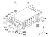
図3及び図4を参照すると、コネクタ10は、ハウジング20と、複数のコンタクト30と、2つのロック部材40とを備えている。ハウジング20は絶縁体からなる。コンタクト30の夫々は導電体からなる。ロック部材40の夫々は金属製である。コネクタ10には、対象物60(図21参照)の被挿入部62を受容する受容部12が形成されている。本実施の形態による受容部12は、ハウジング20の内部に位置する空間である。本実施の形態による受容部12は、前方に開口している。
図5に示されるように、ハウジング20は、1つの主部210と、2つの側部220とを有している。主部210は、ハウジング20のX方向における中間部に位置している。側部220は、ハウジング20のX方向における両側に夫々位置している。主部210のX方向における両側には、側面218が夫々形成されている。側部220は、側面218と夫々対応している。側部220の夫々は、対応する側面218のX方向外側に位置している。ハウジング20は、YZ平面に対して鏡対称な形状を有している。従って、2つの側部220は、YZ平面に対して互いに鏡対称な形状を有している。ハウジング20は、前後方向において後面(後端)24を有している。本実施の形態において、後端24は、主部210及び側部220の後端面(+Y側の端面)で構成される。
図5及び図19を参照すると、主部210の後部(+Y側の部位)には後壁212が形成されている。図3及び図19を参照すると、受容部12は、Y方向において、後壁212の前方に位置しており、X方向において、主部210の側面218を越えて側部220の内部まで延びている。図5及び図6に示されるように、後壁212には、複数の保持部214が形成されている。保持部214は、X方向に並んでいる。図19を参照すると、保持部214の夫々は、後壁212をY方向に貫通して受容部12まで延びている。
図5を参照すると、側部220の夫々は、上板部222と、内壁面224と、2つの外壁226とを有している。図5及び図21を参照すると、上板部222は、平板状の部位である。上板部222は、Y方向において側部220の前端近傍と後端24との間に位置し、Z方向において受容部12の上に位置している。図5を参照すると、内壁面224は、X方向と直交する垂直面である。内壁面224は、上板部222のX方向外側の端に設けられている。外壁226の一つは、側部220の前端近傍に形成されている。外壁226の残りの一つは、側部220の後部に形成されている。外壁226の夫々は、内壁面224のX方向外側に位置しており、内壁面224と平行に延びている。外壁226の夫々は、下端(-Z側の端)において内壁面224に連結されている。
図4及び図5に示されるように、側部220の夫々には、規制部230と、通過路240と、ガイド部250と、圧入部260と、2つの挿入部270と、位置決め部280とが形成されている。換言すれば、ハウジング20は、2つの側部220に夫々形成されている、規制部230と、通過路240と、ガイド部250と、圧入部260と、挿入部270と、位置決め部280とを有している。
規制部230は、上板部222から構成されている。規制部230の上面は、ハウジング20の後端24まで、XY平面、即ちZ方向と直交する水平面上を延びている。このため、金型を使用してハウジング20を作製する際、規制部230を形成し易い。
図5及び図21を参照すると、通過路240は、上板部222の前端近傍に位置する孔である。通過路240は、ハウジング20の外部から受容部12まで延びている。ガイド部250は、直方体形状を有する突起である。ガイド部250は、上板部222の前端近傍に位置し、側面218に沿ってY方向に延びつつ上方に突出している。ガイド部250の上端(+Z側の端)は、Z方向において通過路240の上方に位置している。通過路240は、X方向において規制部230とガイド部250との間に位置している。換言すれば、通過路240は、X方向において規制部230及びガイド部250の夫々と隣り合っている。
図5及び図14を参照すると、圧入部260は、上板部222の後部に位置する孔である。圧入部260は、上板部222から下方(-Z方向)に延びて、側部220を貫通している。圧入部260は、全体としてYZ平面と平行に延びている。図5を参照すると、挿入部270の夫々は、内壁面224と外壁226との間に形成された溝である。挿入部270の夫々は、全体としてYZ平面と平行に延びている。位置決め部280は、側部220の-Y側に位置する外壁226と側部220の+Y側に位置する外壁226との間に位置する空間である。位置決め部280と挿入部270の夫々とは、Y方向において並んでいる。詳しくは、位置決め部280は、Y方向において2つの挿入部270の間に位置している。圧入部260は、側部220のX方向内側の端近傍に位置している。挿入部270及び位置決め部280の夫々は、側部220のX方向外側の端近傍に位置している。
図4に示されるように、本実施の形態によるコンタクト30は、互いに同一形状を有している。図7に示されるように、コンタクト30の夫々は、2つの接続部310と、被保持部320と、被固定部330とを有している。接続部310の夫々は、被保持部320から前方に延びている。被保持部320には、圧入突起が形成されている。被固定部330は、被保持部320から全体として下方に延びている。
図4、図13、図17及び図19を参照すると、コンタクト30の夫々は、後方からハウジング20に圧入されている。詳しくは、コンタクト30の被保持部320は、保持部214に夫々圧入されて保持されている。これにより、ハウジング20は、コンタクト30をX方向に並べるように保持している。図18を参照すると、接続部310の前端の夫々は、受容部12内に突出している。図13を参照すると、被固定部330は、コネクタ10の使用時に、回路基板82(図1参照)に半田付け等によって固定される。
図4に示されるように、本実施の形態において、2つのロック部材40は、YZ平面に対して互いに鏡対称な形状を有している。本実施の形態によるロック部材40の夫々は、打ち抜かれて折り曲げられた1枚の金属板から形成されている。これにより、必要な強度やバネ性を有するロック部材40を、比較的容易に形成できる。但し、本発明は、これに限られない。例えば、ロック部材40の夫々は、複数の金属板を組み合わせて形成されていてもよい。
図4、図8及び図9に示されるように、ロック部材40の夫々は、支持部410と、バネ部420と、ロック部430と、被圧入部440と、連結部450と、止め部460とを有している。本実施の形態において、支持部410及びバネ部420の夫々は、Z方向と直交する平板形状を有しており、ロック部430,被圧入部440及び連結部450の夫々は、X方向と直交する平板形状を有している。但し、本発明は、これに限られない。例えば、支持部410及びバネ部420の夫々は、Z方向と多少斜交していてもよい。また、ロック部430,被圧入部440及び連結部450の夫々は、X方向と多少斜交していてもよい。換言すれば、支持部410及びバネ部420の夫々は、Z方向と交差していればよく、ロック部430,被圧入部440及び連結部450の夫々は、X方向と交差していればよい。
支持部410は、バネ部420を弾性変形可能に片持ち梁状に支持している。ロック部430は、バネ部420の自由端に設けられている。ロック部430は、バネ部420の弾性変形によって、Z方向に移動可能である。被圧入部440及び連結部450の夫々は、支持部410に接続されて下方に延びている。特に、本実施の形態による被圧入部440及び連結部450は、支持部410のX方向における両側に夫々接続されている。止め部460は、連結部450の前部(-Y側の部位)の下端から下方に延びている。換言すれば、連結部450は、支持部410と止め部460とを互いに連結している。止め部460は、被固定部462を有している。被固定部462は、止め部460の下端に位置しており、X方向外側に張り出している。
図4、図13及び図15を参照すると、ロック部材40は、ハウジング20の側部220に上方から夫々取り付けられている。詳しくは、図8から図10までに示されるように、被圧入部440の+Y側の縁面及び-Y側の縁面の夫々には、複数の圧入突起442が形成されている。図13及び図15を参照すると、ロック部材40の夫々の被圧入部440は、ハウジング20の対応する側部220の圧入部260に上方から圧入されて下方に延びている。これにより、ハウジング20は、ロック部材40を保持している。本実施の形態によれば、被圧入部440の圧入突起442(図10参照)の夫々は、Y方向に突出している。但し、本発明は、これに限定されない。被圧入部440がハウジング20に確実に保持される限り、圧入突起442は、Z方向と直交する任意の方向に突出していてもよい。また、圧入突起442は、被圧入部440の+Y側の縁面及び-Y側の縁面の一方のみに設けられていてもよい。
図13から図16までを参照すると、ロック部材40の夫々の連結部450は、ハウジング20の対応する側部220の挿入部270に上方から挿入されている。ロック部材40の夫々の連結部450は、少なくとも部分的に対応する側部220の挿入部270の内部に位置している。止め部460の夫々は、少なくとも部分的に対応する位置決め部280の内部に位置している。これにより、位置決め部280の夫々の前端及び後端は、対応する止め部460のY方向における移動を規制している。位置決め部280の前端は、側部220の-Y側に位置する外壁226の後端であり、位置決め部280の後端は、側部220の+Y側に位置する外壁226の前端である。
図10に示されるように、被圧入部440の下端は、Z方向において止め部460の下端(被固定部462)の上方に位置している。従って、図13を参照すると、ロック部材40をハウジング20に上方から取り付ける際、先ず、止め部460の被固定部462が、位置決め部280に挿入される。これによって、ロック部材40は、XY平面において粗く位置決めされる。次に、被圧入部440が圧入部260に圧入され、連結部450が挿入部270に挿入される。この結果、ロック部材40は、ハウジング20に取り付けられ、ロック部材40のXY平面における位置が固定される。以上の説明から理解されるように、本実施の形態によるロック部材40は、それ自身がXY平面において容易に位置決めされることを可能にする構造を有している。
図13を参照すると、止め部460の被固定部462の夫々は、コネクタ10の使用時に、回路基板82(図1参照)に半田付け等によって固定される。2つの被固定部462がコネクタ10の前端近傍において回路基板82に固定され、複数のコンタクト30の夫々の被固定部330がコネクタ10の後端において回路基板82に固定される。これにより、コネクタ10は、回路基板82に強固に固定される。
また、本実施の形態によるロック部材40の支持部410は、コネクタ10の使用時に、被圧入部440及び止め部460の2つの部位によって強固に保持される。換言すれば、支持部410には、支持部410のZ方向の移動を夫々防止する部位が2つ設けられている。本実施の形態において、この2つの部位は、支持部410のX方向内側に接続された被圧入部440と、支持部410のX方向外側に連結部450を介して間接的に接続された止め部460である。
但し、本発明は、これに限られない。支持部410のZ方向の移動を防止する2つの部位の夫々は、支持部410のどの部位に接続されていてもよい。例えば、止め部460は、支持部410の後端に直接的に接続されていてもよい。被圧入部440や止め部460以外の部位が、支持部410のZ方向の移動を防止してもよい。ロック部材40は、被圧入部440や止め部460に加えて、支持部410の後端に接続された別の被圧入部を有していてもよい。一方、ロック部材40は、支持部410のZ方向の移動を防止する部位を、1つのみ有していてもよい。例えば、ロック部材40は、連結部450や止め部460を有していなくてもよい。
図13及び図15に示されるように、支持部410の夫々は、ハウジング20の対応する規制部230の上に配置されている。バネ部420は、支持部410から前方に延びている。ロック部430は、バネ部420の前端に設けられている。特に、本実施の形態によるバネ部420はX方向において側部を有しており、本実施の形態によるロック部430は、バネ部420のX方向における一方の側部(X方向内側)から下方に延びている。この構造により、バネ部420は長いバネ長を有することができる。例えば、バネ部420の前端をX方向内側に向かって更に長く延ばすことで、バネ部420はより長いバネ長を有することができる。また、図11及び図13に示されるように、バネ部420のX方向におけるサイズは、バネ部420の前方との距離が減少するにつれて小さくなっている。以上の説明から理解されるように、ロック部材40は、ロック部430がZ方向に移動し易い構造を有している。
図11及び図12を参照すると、ロック部430は、X方向において被圧入部440と連結部450との間に位置している。特に、バネ部420と支持部410との間の境界422は、X方向において被圧入部440と連結部450との間に位置している。この構造により、バネ部420は、側部220に安定的に支持され、ロック部430を動かすために必要なバネ力を安定的に発揮する。
図13及び図17を参照すると、ロック部材40の夫々をハウジング20に上方から取り付ける際、ロック部430の夫々は、対応するガイド部250にガイドされて対応する通過路240にスムーズに挿入される。図21を参照すると、ロック部430の夫々は、対応する通過路240を通過して受容部12の内部に突出している(図18参照)。これにより、ロック部430は、対象物60の被挿入部62が受容部12に挿入されて対象物60がコネクタ10と接続されたとき、被挿入部62の被ロック部68の前方への移動を夫々止める(図22参照)。換言すれば、ロック部430の夫々は、対応する被ロック部68をロックする。
図8、図9、図19及び図20に示されるように、ロック部430は、前側部432と、後側部434とを有している。前側部432は、ロック部430のY方向における前側(-Y側)に位置している。後側部434は、ロック部430のY方向における後側(+Y側)に位置している。前側部432及び後側部434の夫々は、Y方向及びZ方向の双方と斜交する平面である。より具体的には、前側部432及び後側部434の夫々は、ロック部430の縁面である。対象物60がコネクタ10に挿入されていないとき、前側部432は、下方及び後方に延びてY方向と第1角度θ1で交差している。対象物60がコネクタ10に挿入されていないとき、後側部434は、下方及び前方に延びてY方向と第2角度θ2で交差している。第1角度θ1及び第2角度θ2の夫々は、0°よりも大きく90°よりも小さい。第2角度θ2は、第1角度θ1よりも大きい。
図21及び図23を参照すると、対象物60を+Y方向に沿ってコネクタ10の受容部12に挿入開始すると、被挿入部62の先端(+Y側の端)がロック部430の夫々の前側部432と突き当たる。対象物60を所定の挿入力Fiで後方に向かって押すと、ロック部430の夫々は上方に移動する。このとき、ロック部430の夫々は、対応するガイド部250によってX方向内側への移動を規制されつつ、上方に移動する。対象物60を後方に押し続けると、上方に移動したロック部430は、被挿入部62の上面をスライドした後、凹部66内に夫々位置する。図18及び図22を参照すると、このとき、接続部310の前端は、被挿入部62の端子64と夫々接触する。換言すれば、対象物60は、コネクタ10と物理的かつ電気的に接続される。
図22を参照すると、対象物60がコネクタ10に接続されているとき、ロック部430の夫々の後側部434は、対象物60の対応する被ロック部68の前に位置している。前述したように、後側部434とY方向との交角は、前側部432とY方向との交角よりも大きい。換言すれば、後側部434の接線は、前側部432の接線よりも大きな角度でY方向と交差している。このため、対象物60をコネクタ10から抜去するためには、対象物60をコネクタ10に挿入する際の挿入力Fiよりも大きな抜去力Frが必要である。
例えば対象物60が衝撃によって前方に向かう力を受けたとき、被ロック部68の夫々が対応する後側部434と突き当たる。このときの前方に向かう力が抜去力Frよりも小さい場合、ロック部430の夫々は、上方に移動することなく対応する被ロック部68の前方への移動を止める。換言すれば、ロック部430の夫々は、対応する被ロック部68をロックし続ける。抜去力Frは、後側部434とY方向との交角や、バネ部420のバネ性を調整することで、通常の衝撃によって生じる力の強度よりも大きい強度を有するように設定可能である。抜去力Frを上述のように比較的大きく設定することで、対象物60のコネクタ10からの意図しない抜去を防止できる。換言すれば、ロック部430の夫々は、対応する被ロック部68を確実にロックできる。
図22及び図23を参照すると、コネクタ10に接続された対象物60を-Y方向に沿ってコネクタ10から抜去開始すると、被ロック部68の夫々が対応する後側部434と突き当たる。前述したように、後側部434とY方向との間の交角は、90°よりも小さい。換言すれば、後側部434の接線は、90°よりも小さな角度でY方向と交差している。このため、対象物60を抜去力Frで前方に向かって引くと、ロック部430の夫々は上方に移動する。このとき、ロック部430の夫々は、対応するガイド部250によってX方向内側への移動を規制されつつ、上方に移動する。換言すれば、抜去力Frは、ロック部430の夫々を実質的に上方のみに移動させる。対象物60を引き続けると、上方に移動したロック部430の夫々は、被挿入部62の上面をスライドした後、被挿入部62の後方に位置する。これにより、対象物60は、コネクタ10から抜去される。
図21及び図22を参照すると、規制部230の夫々は、対象物60がコネクタ10に挿入されたとき、Z方向において対応する被ロック部68の上方に位置して対応する被ロック部68のZ方向における移動を規制している。規制部230の夫々は、対象物60をコネクタ10から抜去する際にも、対応する被ロック部68のZ方向における移動を規制する。仮に、被ロック部68がY方向及びZ方向の双方に対して傾いた状態で後側部434に突き当たった場合、ロック部430は上方に移動せずロックが外れない。しかしながら、規制部230が、Y方向及びZ方向の双方に対して被ロック部68が傾くのを防ぐため、上述の状況は起こらない。特に、本実施の形態によれば、規制部230の周辺には、通過路240を除いて孔が形成されていない。このため、規制部230の夫々は、十分な強度を有しており、対応する被ロック部68のZ方向における移動を、より確実に規制できる。
更に、図15及び図20を参照すると、バネ部420の夫々は、対応する規制部230の上に位置している。即ち、バネ部420の夫々は、対応する規制部230から僅かに上方に離れて位置している。このため、ロック部430の夫々は、下方に押圧されたとしても、下方に殆ど移動できない。換言すれば、ロック部430の夫々は、下方に移動し難く上方に移動し易い。特に、本実施の形態によれば、バネ部420の夫々の全体が対応する規制部230の上に位置している。このため、ロック部430の夫々の下方への移動が、より確実に規制できる。但し、本発明は、これに限られない。バネ部420は、少なくとも部分的に規制部230の上に位置してY方向に延びていてもよい。
図1及び図2を参照すると、本実施の形態によれば、対象物60のコネクタ10からの意図しない抜去を防止できると共に対象物60を抜去力Frで引くだけで、対象物60をコネクタ10から抜去できる。このため、コネクタ10の設置場所が限定されない。更に、コネクタ10は、ロック部材40を操作するための部材や部位を備える必要がない。
本実施の形態は、既に述べた変形例に加えて、更に様々に変形可能である。
図24を参照すると、変形例によるコネクタ10Aは、ロック部材40(図3参照)と少し異なるロック部材40Aを備えていることを除き、コネクタ10(図3参照)の構造と同じ構造を有している。ロック部材40Aは、ロック部430(図23参照)の形状と異なる形状を有するロック部430Aを有していることを除き、ロック部材40の構造と同じ構造を有している。
ロック部430Aは、前側部432Aと、後側部434Aとを有している。前側部432A及び後側部434Aの夫々は、YZ平面において弧形状を有している。前側部432A及び後側部434Aは、ロック部430Aの下端438において互いに繋がっている。前側部432Aは、前側所定点432Pを含んでいる。後側部434Aは、後側所定点434Pを含んでいる。対象物60がコネクタ10Aに挿入されていないとき、前側所定点432P及び後側所定点434Pは、Z方向において互いに同じ位置にある。対象物60がコネクタ10Aに挿入されていないとき、前側所定点432Pにおける第1接線(接線)TL1は、X方向と直交する垂直面(YZ平面)内を下方及び後方に延びてY方向と第1角度θ1で交差している。対象物60がコネクタ10Aに挿入されていないとき、後側所定点434Pにおける第2接線(接線)TL2は、YZ平面内において下方及び前方に延びてY方向と第2角度θ2で交差している。第1角度θ1及び第2角度θ2の夫々は、0°よりも大きく90°よりも小さい。第2角度θ2は、第1角度θ1よりも大きい。
前側所定点432P及び後側所定点434Pの夫々は、Z方向において対象物60の上面の位置と同じ位置に位置している。このため、対象物60をコネクタ10Aに挿入開始すると、被挿入部62の先端(+Y側の端)が前側所定点432Pと突き当たる。また、コネクタ10Aに接続された対象物60を、コネクタ10から抜去開始すると、被ロック部68が後側所定点434Pと突き当たる。この構造により、前述した本実施の形態と同様に、対象物60のコネクタ10Aからの意図しない抜去を防止できると共に対象物60を引くだけでコネクタ10Aから抜去できる。
以上の説明から理解されるように、前側所定点432P及び後側所定点434PのZ方向における位置は、対象物60のZ方向におけるサイズによって異なる。このため、本変形例において、前側部432Aの円弧を後側部434Aの円弧に比べて全体的に緩やかに湾曲させている。この構造により、前側所定点432P及び後側所定点434Pの夫々が下端438の上方に位置する限り、接線TL2とY方向との交角を、接線TL1とY方向との交角よりも大きくできる。
前側部432Aは、ロック部430Aの前側に位置する部位の一部であってもよい。同様に、後側部434Aは、ロック部430Aの後側に位置する部位の一部であってもよい。また、前側部432A及び後側部434Aの夫々は、弧形状を有していなくてもよい。例えば、前側部432Aは、Y方向及びZ方向の双方と斜交する平面であってもよい。この場合、対象物60がコネクタ10Aに挿入されていないとき、前側部432Aは、後側所定点434P(Z方向において前側部432Aの上端と下端との間に位置する点)における第2角度θ2よりも小さな第1角度θ1でY方向と交差していればよい。同様に、後側部434Aは、Y方向及びZ方向の双方と斜交する平面であってもよい。この場合、対象物60がコネクタ10Aに挿入されていないとき、後側部434Aは、前側所定点432P(Z方向において後側部434Aの上端と下端との間に位置する点)における第1角度θ1よりも大きな第2角度θ2でY方向と交差していればよい。
上述した本実施の形態や変形例は、更に様々に変形可能である。例えば、本発明は、平板形状以外の形状を有している対象物を挿入可能なコネクタにも適用可能である。コネクタは、ハウジング、コンタクト及びロック部材に加えて別の部材を備えていてもよい。コンタクトは、どのような形状を有していてもよい。ロック部材は、互いに同一形状を有していてもよい。また、ロック部材の数は、1つでもよいし、3つ以上でもよい。但し、対象物をバランスよく確実にロックするという観点からは、本実施の形態のようにコネクタが互いに鏡対称な2つのロック部材を備えることが好ましい。
更に、ハウジングやロック部材は、様々に変形可能である。例えば、ハウジングは、ガイド部を有していなくてもよい。この場合、通過路は、主部の側面と側部の規制部との間に形成された隙間であってもよい。ロック部材のバネ部は、コネクタの前方から後方に延びていてもよい。この場合、規制部は、ハウジングの前端まで延びていてもよい。また、ハウジングの挿入部や位置決め部の夫々は、側部をZ方向に貫通する孔であってもよい。
本発明は2015年8月7日に日本国特許庁に提出された日本特許出願第2015-156974号に基づいており、その内容は参照することにより本明細書の一部をなす。
本発明の最良の実施の形態について説明したが、当業者には明らかなように、本発明の精神を逸脱しない範囲で実施の形態を変形することが可能であり、そのような実施の形態は本発明の範囲に属するものである。
10,10A コネクタ
12 受容部
20 ハウジング
24 後面(後端)
210 主部
212 後壁
214 保持部
218 側面
220 側部
222 上板部
224 内壁面
226 外壁
230 規制部
240 通過路
250 ガイド部
260 圧入部
270 挿入部
280 位置決め部
30 コンタクト
310 接続部
320 被保持部
330 被固定部
40,40A ロック部材
410 支持部
420 バネ部
422 境界
430,430A ロック部
432,432A 前側部
432P 前側所定点
434,434A 後側部
434P 後側所定点
438 下端
440 被圧入部
442 圧入突起
450 連結部
460 止め部
462 被固定部
60 FPC(対象物)
62 被挿入部
64 端子
66 凹部
68 被ロック部
80 構造体
82 固定対象物(回路基板)
84 壁部
88 窓
TL1 第1接線(接線)
TL2 第2接線(接線)
900 電気コネクタ(コネクタ)
910 絶縁ハウジング(ハウジング)
912 操作カバー
920 ロック部材
922 係止ロック部(ロック部)
922R 後側部
990 信号伝送媒体(対象物)
992 係合位置決め部(被ロック孔)
12 受容部
20 ハウジング
24 後面(後端)
210 主部
212 後壁
214 保持部
218 側面
220 側部
222 上板部
224 内壁面
226 外壁
230 規制部
240 通過路
250 ガイド部
260 圧入部
270 挿入部
280 位置決め部
30 コンタクト
310 接続部
320 被保持部
330 被固定部
40,40A ロック部材
410 支持部
420 バネ部
422 境界
430,430A ロック部
432,432A 前側部
432P 前側所定点
434,434A 後側部
434P 後側所定点
438 下端
440 被圧入部
442 圧入突起
450 連結部
460 止め部
462 被固定部
60 FPC(対象物)
62 被挿入部
64 端子
66 凹部
68 被ロック部
80 構造体
82 固定対象物(回路基板)
84 壁部
88 窓
TL1 第1接線(接線)
TL2 第2接線(接線)
900 電気コネクタ(コネクタ)
910 絶縁ハウジング(ハウジング)
912 操作カバー
920 ロック部材
922 係止ロック部(ロック部)
922R 後側部
990 信号伝送媒体(対象物)
992 係合位置決め部(被ロック孔)
Claims (16)
- 被ロック部を有する対象物を前後方向に沿ってコネクタの前方から挿入可能なコネクタであって、
ハウジングと、複数のコンタクトと、ロック部材とを備えており、
前記ハウジングは、前記コンタクトを前記前後方向と直交するピッチ方向に並べて保持しており、
前記ハウジングは、前記ロック部材を保持しており、
前記ロック部材は、前記対象物の前記被ロック部をロックするロック部を有しており、
前記ロック部は、前側部及び後側部を有しており、
前記前側部は、前記ロック部の前記前後方向における前側に位置しており、
前記後側部は、前記ロック部の前記前後方向における後側に位置しており、
前記前側部は、前側所定点を含んでおり、
前記後側部は、後側所定点を含んでおり、
前記対象物が前記コネクタに挿入されていないとき、前記前側所定点及び前記後側所定点は、前記前後方向及び前記ピッチ方向の双方と直交する上下方向において互いに同じ位置に位置しており、
前記対象物が前記コネクタに挿入されていないとき、前記ロック部の前記前側所定点における接線は、前記ピッチ方向と直交する垂直面内を下方及び後方に延びて前記前後方向と第1角度で交差しており、
前記対象物が前記コネクタに挿入されていないとき、前記ロック部の前記後側所定点における接線は、前記垂直面内において下方及び前方に延びて前記前後方向と第2角度で交差しており、
前記第1角度及び前記第2角度の夫々は、0°よりも大きく90°よりも小さく、
前記第2角度は、前記第1角度よりも大きい
コネクタ。 - 請求項1記載のコネクタであって、
前記前側部は、前記前後方向及び前記上下方向の双方と斜交する平面であり、
前記対象物が前記コネクタに挿入されていないとき、前記前側部は、前記前後方向と前記第1角度で交差している
コネクタ。 - 請求項1又は請求項2記載のコネクタであって、
前記後側部は、前記前後方向及び前記上下方向の双方と斜交する平面であり、
前記対象物が前記コネクタに挿入されていないとき、前記後側部は、前記前後方向と前記第2角度で交差している
コネクタ。 - 被ロック部を有する対象物を前後方向に沿ってコネクタの前方から挿入可能なコネクタであって、
ハウジングと、複数のコンタクトと、ロック部材とを備えており、
前記ハウジングは、前記コンタクトを前記前後方向と直交するピッチ方向に並べて保持しており、
前記ハウジングは、前記ロック部材を保持しており、
前記ロック部材は、前記対象物の前記被ロック部をロックするロック部を有しており、
前記ロック部は、前側部及び後側部を有しており、
前記前側部は、前記ロック部の前記前後方向における前側に位置しており、
前記後側部は、前記ロック部の前記前後方向における後側に位置しており、
前記前側部及び前記後側部の夫々は、前記前後方向と斜交し且つ前記前後方向及び前記ピッチ方向の双方と直交する上下方向と斜交する平面であり、
前記対象物が前記コネクタに挿入されていないとき、前記前側部は、下方及び後方に延びて前記前後方向と第1角度で交差しており、
前記対象物が前記コネクタに挿入されていないとき、前記後側部は、下方及び前方に延びて前記前後方向と第2角度で交差しており、
前記第1角度及び前記第2角度の夫々は、0°よりも大きく90°よりも小さく、
前記第2角度は、前記第1角度よりも大きい
コネクタ。 - 請求項1から請求項4までのいずれかに記載のコネクタであって、
前記ロック部材は折り曲げられた1枚の金属板からなる
コネクタ。 - 請求項1から請求項5までのいずれかに記載のコネクタであって、
前記ハウジングは、規制部を有しており、
前記規制部は、前記対象物が前記コネクタに挿入されたとき、前記上下方向において前記被ロック部の上方に位置して前記被ロック部の前記上下方向における移動を規制し、
前記ロック部材は、支持部と、バネ部とを有しており、
前記支持部は、前記バネ部を弾性変形可能に支持しており、
前記バネ部は、前記上下方向と交差する平板形状を有しており、
前記バネ部は、少なくとも部分的に前記規制部の上に位置して前記前後方向に延びており、
前記ロック部は、前記バネ部から下方に延びている
コネクタ。 - 請求項6記載のコネクタであって、
前記バネ部全体が前記規制部の上に位置している
コネクタ。 - 請求項6又は請求項7記載のコネクタであって、
前記バネ部は、前記支持部から前方に延びており、
前記バネ部の前記ピッチ方向におけるサイズは、前記バネ部の前方との距離が減少するにつれて小さくなり、
前記バネ部は、前記前後方向において前端を有しており、
前記ロック部は、前記バネ部の前記前端に設けられている
コネクタ。 - 請求項8記載のコネクタであって、
前記ハウジングは、前記前後方向において後端を有しており、
前記規制部は、前記ハウジングの前記後端まで延びている
コネクタ。 - 請求項6から請求項9までのいずれかに記載のコネクタであって、
前記ロック部は、前記ピッチ方向と交差する平板形状を有しており、
前記バネ部は、前記ピッチ方向において側部を有しており、
前記ロック部は、前記バネ部の前記ピッチ方向における一方の前記側部から下方に延びている
コネクタ。 - 請求項6から請求項10までのいずれかに記載のコネクタであって、
前記コネクタには、前記対象物を受容する受容部が形成されており、
前記ハウジングには、前記ハウジングの外部から前記受容部まで延びる通過路が形成されており、
前記通過路は、前記ピッチ方向において前記規制部と隣り合っており、
前記ロック部は、前記通過路を通過して前記受容部の内部に突出している
コネクタ。 - 請求項11記載のコネクタであって、
前記ハウジングは、ガイド部を有しており、
前記通過路は、前記ピッチ方向において前記規制部と前記ガイド部との間に位置しており、
前記ガイド部は、前記上下方向において上端を有しており、
前記ガイド部の前記上端は、前記上下方向において前記通過路の上方に位置している
コネクタ。 - 請求項6から請求項12までのいずれかに記載のコネクタであって、
前記支持部には、前記支持部の前記上下方向の移動を防止する部位が2つ設けられている
コネクタ。 - 請求項6から請求項13までのいずれかに記載のコネクタであって、
前記ロック部材は、圧入突起が形成された被圧入部を有しており、
前記被圧入部は、前記ハウジングに圧入されて下方に延びており、
前記被圧入部の前記圧入突起は、前記上下方向と直交する方向に突出している
コネクタ。 - 請求項14記載のコネクタであって、
前記ロック部材は、連結部と、止め部とを有しており、
前記連結部は、前記支持部と前記止め部とを互いに連結しており、
前記被圧入部及び前記連結部の夫々は、前記ピッチ方向と交差する平板形状を有しており、
前記ロック部材は、前記バネ部と前記支持部との間に境界を有しており、
前記境界は、前記ピッチ方向において前記被圧入部と前記連結部との間に位置している
コネクタ。 - 請求項15記載のコネクタであって、
前記ハウジングには、挿入部と、位置決め部とが形成されており、
前記挿入部と前記位置決め部とは、前記前後方向において並んでおり、
前記被圧入部及び前記連結部の夫々は、前記支持部に接続されて下方に延びており、
前記止め部は、前記連結部から下方に延びており、
前記被圧入部は、前記上下方向において下端を有しており、
前記止め部は、前記上下方向において下端を有しており、
前記被圧入部の前記下端は、前記上下方向において前記止め部の前記下端の上方に位置しており、
前記連結部は、少なくとも部分的に前記挿入部の内部に位置しており、
前記止め部は、少なくとも部分的に前記位置決め部の内部に位置している
コネクタ。
Applications Claiming Priority (2)
| Application Number | Priority Date | Filing Date | Title |
|---|---|---|---|
| JP2015-156974 | 2015-08-07 | ||
| JP2015156974A JP6199348B2 (ja) | 2015-08-07 | 2015-08-07 | コネクタ |
Publications (1)
| Publication Number | Publication Date |
|---|---|
| WO2017026164A1 true WO2017026164A1 (ja) | 2017-02-16 |
Family
ID=57983046
Family Applications (1)
| Application Number | Title | Priority Date | Filing Date |
|---|---|---|---|
| PCT/JP2016/066351 Ceased WO2017026164A1 (ja) | 2015-08-07 | 2016-06-02 | コネクタ |
Country Status (3)
| Country | Link |
|---|---|
| JP (1) | JP6199348B2 (ja) |
| TW (1) | TWI571013B (ja) |
| WO (1) | WO2017026164A1 (ja) |
Families Citing this family (1)
| Publication number | Priority date | Publication date | Assignee | Title |
|---|---|---|---|---|
| KR102942069B1 (ko) * | 2024-02-21 | 2026-03-23 | 이형철 | 방수형 플렉서블 케이블용 커넥터 |
Citations (4)
| Publication number | Priority date | Publication date | Assignee | Title |
|---|---|---|---|---|
| JP2006073229A (ja) * | 2004-08-31 | 2006-03-16 | Optrex Corp | 配線基板とコネクタとの接続構造 |
| JP2007122894A (ja) * | 2005-10-25 | 2007-05-17 | Kyocera Elco Corp | コネクタ |
| JP2009064577A (ja) * | 2007-09-04 | 2009-03-26 | Kyocera Elco Corp | コネクタ |
| JP2013125668A (ja) * | 2011-12-15 | 2013-06-24 | Daiichi Seiko Co Ltd | 電気コネクタ |
Family Cites Families (1)
| Publication number | Priority date | Publication date | Assignee | Title |
|---|---|---|---|---|
| JP5480990B1 (ja) * | 2013-03-28 | 2014-04-23 | 日本航空電子工業株式会社 | コネクタ組立体 |
-
2015
- 2015-08-07 JP JP2015156974A patent/JP6199348B2/ja not_active Expired - Fee Related
-
2016
- 2016-06-02 WO PCT/JP2016/066351 patent/WO2017026164A1/ja not_active Ceased
- 2016-06-03 TW TW105117519A patent/TWI571013B/zh not_active IP Right Cessation
Patent Citations (4)
| Publication number | Priority date | Publication date | Assignee | Title |
|---|---|---|---|---|
| JP2006073229A (ja) * | 2004-08-31 | 2006-03-16 | Optrex Corp | 配線基板とコネクタとの接続構造 |
| JP2007122894A (ja) * | 2005-10-25 | 2007-05-17 | Kyocera Elco Corp | コネクタ |
| JP2009064577A (ja) * | 2007-09-04 | 2009-03-26 | Kyocera Elco Corp | コネクタ |
| JP2013125668A (ja) * | 2011-12-15 | 2013-06-24 | Daiichi Seiko Co Ltd | 電気コネクタ |
Also Published As
| Publication number | Publication date |
|---|---|
| JP2017037737A (ja) | 2017-02-16 |
| JP6199348B2 (ja) | 2017-09-20 |
| TW201707302A (zh) | 2017-02-16 |
| TWI571013B (zh) | 2017-02-11 |
Similar Documents
| Publication | Publication Date | Title |
|---|---|---|
| TWI466395B (zh) | 電連接器 | |
| US8292648B2 (en) | Flexible cable connecting structure and flexible cable connector | |
| CN104364975B (zh) | 电线与基板的连接器 | |
| CN108631101B (zh) | 连接器 | |
| CN111193125B (zh) | 连接器 | |
| KR101472663B1 (ko) | 전기 커넥터 | |
| TWI552448B (zh) | 連接器 | |
| KR20210004828A (ko) | 커넥터 조립체 | |
| TWI555277B (zh) | 電連接器 | |
| CN103633461A (zh) | 用于连接器系统的连接器组件 | |
| KR101531609B1 (ko) | 커넥터 | |
| CN107925181B (zh) | 连接器 | |
| CN105723573B (zh) | 连接器 | |
| JP2024068763A (ja) | 電気コネクタ | |
| JP2016157643A (ja) | コネクタ組立体 | |
| JP5909586B1 (ja) | 電気コネクタ | |
| US9774119B2 (en) | Connector | |
| CN104868311B (zh) | 连接器及连接器组装件 | |
| JP6199348B2 (ja) | コネクタ | |
| JP2007179821A (ja) | 電気コネクタ | |
| JP2011238507A (ja) | Usbコネクタ | |
| JP6100430B2 (ja) | 基板接続構造 | |
| JP5093824B2 (ja) | コネクタ | |
| JP2011023329A (ja) | 電線対基板コネクタ | |
| US20070042629A1 (en) | Latch for connector |
Legal Events
| Date | Code | Title | Description |
|---|---|---|---|
| 121 | Ep: the epo has been informed by wipo that ep was designated in this application |
Ref document number: 16834861 Country of ref document: EP Kind code of ref document: A1 |
|
| NENP | Non-entry into the national phase |
Ref country code: DE |
|
| 122 | Ep: pct application non-entry in european phase |
Ref document number: 16834861 Country of ref document: EP Kind code of ref document: A1 |