WO2017018468A1 - Cholesteric resin laminate, production method, and use - Google Patents
Cholesteric resin laminate, production method, and use Download PDFInfo
- Publication number
- WO2017018468A1 WO2017018468A1 PCT/JP2016/072082 JP2016072082W WO2017018468A1 WO 2017018468 A1 WO2017018468 A1 WO 2017018468A1 JP 2016072082 W JP2016072082 W JP 2016072082W WO 2017018468 A1 WO2017018468 A1 WO 2017018468A1
- Authority
- WO
- WIPO (PCT)
- Prior art keywords
- group
- cholesteric resin
- layer
- cholesteric
- resin layer
- Prior art date
Links
- 239000011347 resin Substances 0.000 title claims abstract description 280
- 229920005989 resin Polymers 0.000 title claims abstract description 280
- 230000003098 cholesteric effect Effects 0.000 title claims abstract description 275
- 238000004519 manufacturing process Methods 0.000 title claims abstract description 41
- 239000000463 material Substances 0.000 claims abstract description 120
- 239000000758 substrate Substances 0.000 claims abstract description 17
- 239000010410 layer Substances 0.000 claims description 303
- 150000001875 compounds Chemical class 0.000 claims description 107
- 239000000203 mixture Substances 0.000 claims description 83
- 239000004973 liquid crystal related substance Substances 0.000 claims description 72
- 239000004372 Polyvinyl alcohol Substances 0.000 claims description 59
- 229920002451 polyvinyl alcohol Polymers 0.000 claims description 59
- 239000000853 adhesive Substances 0.000 claims description 51
- 230000001070 adhesive effect Effects 0.000 claims description 50
- 125000004432 carbon atom Chemical group C* 0.000 claims description 39
- -1 acryl group Chemical group 0.000 claims description 34
- 239000003795 chemical substances by application Substances 0.000 claims description 29
- 125000000217 alkyl group Chemical group 0.000 claims description 24
- 239000012790 adhesive layer Substances 0.000 claims description 19
- 125000001424 substituent group Chemical group 0.000 claims description 12
- 125000003277 amino group Chemical group 0.000 claims description 11
- 125000003178 carboxy group Chemical group [H]OC(*)=O 0.000 claims description 11
- 125000004093 cyano group Chemical group *C#N 0.000 claims description 11
- 125000005843 halogen group Chemical group 0.000 claims description 11
- 125000002887 hydroxy group Chemical group [H]O* 0.000 claims description 10
- 125000003700 epoxy group Chemical group 0.000 claims description 7
- 125000004435 hydrogen atom Chemical group [H]* 0.000 claims description 7
- 125000003396 thiol group Chemical group [H]S* 0.000 claims description 7
- 125000002947 alkylene group Chemical group 0.000 claims description 6
- SMEGJBVQLJJKKX-HOTMZDKISA-N [(2R,3S,4S,5R,6R)-5-acetyloxy-3,4,6-trihydroxyoxan-2-yl]methyl acetate Chemical compound CC(=O)OC[C@@H]1[C@H]([C@@H]([C@H]([C@@H](O1)O)OC(=O)C)O)O SMEGJBVQLJJKKX-HOTMZDKISA-N 0.000 claims description 5
- 229940081735 acetylcellulose Drugs 0.000 claims description 5
- 125000003545 alkoxy group Chemical group 0.000 claims description 5
- 125000004453 alkoxycarbonyl group Chemical group 0.000 claims description 5
- 229920002301 cellulose acetate Polymers 0.000 claims description 5
- 125000003504 2-oxazolinyl group Chemical group O1C(=NCC1)* 0.000 claims description 4
- OXPDQFOKSZYEMJ-UHFFFAOYSA-N 2-phenylpyrimidine Chemical class C1=CC=CC=C1C1=NC=CC=N1 OXPDQFOKSZYEMJ-UHFFFAOYSA-N 0.000 claims description 4
- UFWIBTONFRDIAS-UHFFFAOYSA-N Naphthalene Chemical compound C1=CC=CC2=CC=CC=C21 UFWIBTONFRDIAS-UHFFFAOYSA-N 0.000 claims description 4
- MWPLVEDNUUSJAV-UHFFFAOYSA-N anthracene Chemical compound C1=CC=CC2=CC3=CC=CC=C3C=C21 MWPLVEDNUUSJAV-UHFFFAOYSA-N 0.000 claims description 4
- ZUOUZKKEUPVFJK-UHFFFAOYSA-N diphenyl Chemical compound C1=CC=CC=C1C1=CC=CC=C1 ZUOUZKKEUPVFJK-UHFFFAOYSA-N 0.000 claims description 4
- 125000001997 phenyl group Chemical group [H]C1=C([H])C([H])=C(*)C([H])=C1[H] 0.000 claims description 4
- 125000000547 substituted alkyl group Chemical group 0.000 claims description 4
- 125000000446 sulfanediyl group Chemical group *S* 0.000 claims description 4
- YJTKZCDBKVTVBY-UHFFFAOYSA-N 1,3-Diphenylbenzene Chemical group C1=CC=CC=C1C1=CC=CC(C=2C=CC=CC=2)=C1 YJTKZCDBKVTVBY-UHFFFAOYSA-N 0.000 claims description 3
- AUXIEQKHXAYAHG-UHFFFAOYSA-N 1-phenylcyclohexane-1-carbonitrile Chemical class C=1C=CC=CC=1C1(C#N)CCCCC1 AUXIEQKHXAYAHG-UHFFFAOYSA-N 0.000 claims description 3
- WLNDDIWESXCXHM-UHFFFAOYSA-N 2-phenyl-1,4-dioxane Chemical class C1OCCOC1C1=CC=CC=C1 WLNDDIWESXCXHM-UHFFFAOYSA-N 0.000 claims description 3
- 125000003903 2-propenyl group Chemical group [H]C([*])([H])C([H])=C([H])[H] 0.000 claims description 3
- 239000005711 Benzoic acid Substances 0.000 claims description 3
- WPYMKLBDIGXBTP-UHFFFAOYSA-N Benzoic acid Natural products OC(=O)C1=CC=CC=C1 WPYMKLBDIGXBTP-UHFFFAOYSA-N 0.000 claims description 3
- VZCYOOQTPOCHFL-OWOJBTEDSA-N Fumaric acid Chemical group OC(=O)\C=C\C(O)=O VZCYOOQTPOCHFL-OWOJBTEDSA-N 0.000 claims description 3
- 125000005083 alkoxyalkoxy group Chemical group 0.000 claims description 3
- 125000005194 alkoxycarbonyloxy group Chemical group 0.000 claims description 3
- 125000005370 alkoxysilyl group Chemical group 0.000 claims description 3
- 125000005196 alkyl carbonyloxy group Chemical group 0.000 claims description 3
- 125000004069 aziridinyl group Chemical group 0.000 claims description 3
- 125000005337 azoxy group Chemical group [N+]([O-])(=N*)* 0.000 claims description 3
- 235000010233 benzoic acid Nutrition 0.000 claims description 3
- 229910052799 carbon Inorganic materials 0.000 claims description 3
- 150000001925 cycloalkenes Chemical class 0.000 claims description 3
- 125000005647 linker group Chemical group 0.000 claims description 3
- 125000000449 nitro group Chemical group [O-][N+](*)=O 0.000 claims description 3
- 125000003566 oxetanyl group Chemical group 0.000 claims description 3
- 125000000168 pyrrolyl group Chemical group 0.000 claims description 3
- 125000002053 thietanyl group Chemical group 0.000 claims description 3
- 125000000391 vinyl group Chemical group [H]C([*])=C([H])[H] 0.000 claims description 3
- OKTJSMMVPCPJKN-UHFFFAOYSA-N Carbon Chemical compound [C] OKTJSMMVPCPJKN-UHFFFAOYSA-N 0.000 claims description 2
- 239000004305 biphenyl Substances 0.000 claims description 2
- 235000010290 biphenyl Nutrition 0.000 claims description 2
- OPYYWWIJPHKUDZ-UHFFFAOYSA-N phenyl cyclohexanecarboxylate Chemical compound C1CCCCC1C(=O)OC1=CC=CC=C1 OPYYWWIJPHKUDZ-UHFFFAOYSA-N 0.000 claims description 2
- 238000010438 heat treatment Methods 0.000 abstract description 27
- 239000002585 base Substances 0.000 description 46
- 230000008859 change Effects 0.000 description 30
- 239000007788 liquid Substances 0.000 description 28
- 238000000034 method Methods 0.000 description 28
- 238000011282 treatment Methods 0.000 description 18
- 239000000047 product Substances 0.000 description 17
- 239000003431 cross linking reagent Substances 0.000 description 14
- 239000004986 Cholesteric liquid crystals (ChLC) Substances 0.000 description 12
- 230000003595 spectral effect Effects 0.000 description 12
- 230000003287 optical effect Effects 0.000 description 11
- PCHJSUWPFVWCPO-UHFFFAOYSA-N gold Chemical compound [Au] PCHJSUWPFVWCPO-UHFFFAOYSA-N 0.000 description 10
- 239000010931 gold Substances 0.000 description 10
- 229910052737 gold Inorganic materials 0.000 description 10
- 239000004094 surface-active agent Substances 0.000 description 10
- 230000000052 comparative effect Effects 0.000 description 9
- 238000000465 moulding Methods 0.000 description 9
- NIXOWILDQLNWCW-UHFFFAOYSA-M Acrylate Chemical compound [O-]C(=O)C=C NIXOWILDQLNWCW-UHFFFAOYSA-M 0.000 description 8
- 239000007864 aqueous solution Substances 0.000 description 8
- 239000002904 solvent Substances 0.000 description 8
- 238000005259 measurement Methods 0.000 description 7
- UWCWUCKPEYNDNV-LBPRGKRZSA-N 2,6-dimethyl-n-[[(2s)-pyrrolidin-2-yl]methyl]aniline Chemical compound CC1=CC=CC(C)=C1NC[C@H]1NCCC1 UWCWUCKPEYNDNV-LBPRGKRZSA-N 0.000 description 6
- 238000006243 chemical reaction Methods 0.000 description 6
- 238000004049 embossing Methods 0.000 description 6
- 230000001105 regulatory effect Effects 0.000 description 6
- 239000005268 rod-like liquid crystal Substances 0.000 description 6
- 239000000126 substance Substances 0.000 description 6
- 229920002284 Cellulose triacetate Polymers 0.000 description 5
- NNLVGZFZQQXQNW-ADJNRHBOSA-N [(2r,3r,4s,5r,6s)-4,5-diacetyloxy-3-[(2s,3r,4s,5r,6r)-3,4,5-triacetyloxy-6-(acetyloxymethyl)oxan-2-yl]oxy-6-[(2r,3r,4s,5r,6s)-4,5,6-triacetyloxy-2-(acetyloxymethyl)oxan-3-yl]oxyoxan-2-yl]methyl acetate Chemical compound O([C@@H]1O[C@@H]([C@H]([C@H](OC(C)=O)[C@H]1OC(C)=O)O[C@H]1[C@@H]([C@@H](OC(C)=O)[C@H](OC(C)=O)[C@@H](COC(C)=O)O1)OC(C)=O)COC(=O)C)[C@@H]1[C@@H](COC(C)=O)O[C@@H](OC(C)=O)[C@H](OC(C)=O)[C@H]1OC(C)=O NNLVGZFZQQXQNW-ADJNRHBOSA-N 0.000 description 5
- 238000013461 design Methods 0.000 description 5
- 230000000694 effects Effects 0.000 description 5
- 239000012948 isocyanate Substances 0.000 description 5
- 239000000155 melt Substances 0.000 description 5
- 229910052751 metal Inorganic materials 0.000 description 5
- 239000002184 metal Substances 0.000 description 5
- 238000001125 extrusion Methods 0.000 description 4
- 239000003999 initiator Substances 0.000 description 4
- IQPQWNKOIGAROB-UHFFFAOYSA-N isocyanate group Chemical group [N-]=C=O IQPQWNKOIGAROB-UHFFFAOYSA-N 0.000 description 4
- 150000002513 isocyanates Chemical class 0.000 description 4
- 238000002156 mixing Methods 0.000 description 4
- 239000000178 monomer Substances 0.000 description 4
- 230000008569 process Effects 0.000 description 4
- XLYOFNOQVPJJNP-UHFFFAOYSA-N water Substances O XLYOFNOQVPJJNP-UHFFFAOYSA-N 0.000 description 4
- 125000001140 1,4-phenylene group Chemical group [H]C1=C([H])C([*:2])=C([H])C([H])=C1[*:1] 0.000 description 3
- 125000004959 2,6-naphthylene group Chemical group [H]C1=C([H])C2=C([H])C([*:1])=C([H])C([H])=C2C([H])=C1[*:2] 0.000 description 3
- 239000004593 Epoxy Substances 0.000 description 3
- 230000008901 benefit Effects 0.000 description 3
- 238000004132 cross linking Methods 0.000 description 3
- 230000007547 defect Effects 0.000 description 3
- 230000001747 exhibiting effect Effects 0.000 description 3
- 238000006116 polymerization reaction Methods 0.000 description 3
- 239000002356 single layer Substances 0.000 description 3
- 239000007787 solid Substances 0.000 description 3
- 125000004955 1,4-cyclohexylene group Chemical group [H]C1([H])C([H])([H])C([H])([*:1])C([H])([H])C([H])([H])C1([H])[*:2] 0.000 description 2
- VVBLNCFGVYUYGU-UHFFFAOYSA-N 4,4'-Bis(dimethylamino)benzophenone Chemical compound C1=CC(N(C)C)=CC=C1C(=O)C1=CC=C(N(C)C)C=C1 VVBLNCFGVYUYGU-UHFFFAOYSA-N 0.000 description 2
- HBAQYPYDRFILMT-UHFFFAOYSA-N 8-[3-(1-cyclopropylpyrazol-4-yl)-1H-pyrazolo[4,3-d]pyrimidin-5-yl]-3-methyl-3,8-diazabicyclo[3.2.1]octan-2-one Chemical class C1(CC1)N1N=CC(=C1)C1=NNC2=C1N=C(N=C2)N1C2C(N(CC1CC2)C)=O HBAQYPYDRFILMT-UHFFFAOYSA-N 0.000 description 2
- KWOLFJPFCHCOCG-UHFFFAOYSA-N Acetophenone Chemical compound CC(=O)C1=CC=CC=C1 KWOLFJPFCHCOCG-UHFFFAOYSA-N 0.000 description 2
- GUUVPOWQJOLRAS-UHFFFAOYSA-N Diphenyl disulfide Chemical compound C=1C=CC=CC=1SSC1=CC=CC=C1 GUUVPOWQJOLRAS-UHFFFAOYSA-N 0.000 description 2
- RWNKSTSCBHKHTB-UHFFFAOYSA-N Hexachloro-1,3-butadiene Chemical compound ClC(Cl)=C(Cl)C(Cl)=C(Cl)Cl RWNKSTSCBHKHTB-UHFFFAOYSA-N 0.000 description 2
- 239000005057 Hexamethylene diisocyanate Substances 0.000 description 2
- QCWXUUIWCKQGHC-UHFFFAOYSA-N Zirconium Chemical compound [Zr] QCWXUUIWCKQGHC-UHFFFAOYSA-N 0.000 description 2
- 239000002253 acid Substances 0.000 description 2
- NIXOWILDQLNWCW-UHFFFAOYSA-N acrylic acid group Chemical group C(C=C)(=O)O NIXOWILDQLNWCW-UHFFFAOYSA-N 0.000 description 2
- 239000012298 atmosphere Substances 0.000 description 2
- ISAOCJYIOMOJEB-UHFFFAOYSA-N benzoin Chemical compound C=1C=CC=CC=1C(O)C(=O)C1=CC=CC=C1 ISAOCJYIOMOJEB-UHFFFAOYSA-N 0.000 description 2
- 230000015572 biosynthetic process Effects 0.000 description 2
- 239000003054 catalyst Substances 0.000 description 2
- 239000012461 cellulose resin Substances 0.000 description 2
- 238000003851 corona treatment Methods 0.000 description 2
- 238000005034 decoration Methods 0.000 description 2
- 238000004090 dissolution Methods 0.000 description 2
- 238000007756 gravure coating Methods 0.000 description 2
- RRAMGCGOFNQTLD-UHFFFAOYSA-N hexamethylene diisocyanate Chemical compound O=C=NCCCCCCN=C=O RRAMGCGOFNQTLD-UHFFFAOYSA-N 0.000 description 2
- 125000001165 hydrophobic group Chemical group 0.000 description 2
- 230000001678 irradiating effect Effects 0.000 description 2
- 239000012299 nitrogen atmosphere Substances 0.000 description 2
- WXZMFSXDPGVJKK-UHFFFAOYSA-N pentaerythritol Chemical compound OCC(CO)(CO)CO WXZMFSXDPGVJKK-UHFFFAOYSA-N 0.000 description 2
- 230000010287 polarization Effects 0.000 description 2
- 229920000728 polyester Polymers 0.000 description 2
- 230000000379 polymerizing effect Effects 0.000 description 2
- 229920000098 polyolefin Polymers 0.000 description 2
- 238000000926 separation method Methods 0.000 description 2
- 239000011734 sodium Substances 0.000 description 2
- 238000004381 surface treatment Methods 0.000 description 2
- 229910052726 zirconium Inorganic materials 0.000 description 2
- PSQYTAPXSHCGMF-BQYQJAHWSA-N β-ionone Chemical compound CC(=O)\C=C\C1=C(C)CCCC1(C)C PSQYTAPXSHCGMF-BQYQJAHWSA-N 0.000 description 2
- SFEOKXHPFMOVRM-UHFFFAOYSA-N (+)-(S)-gamma-ionone Natural products CC(=O)C=CC1C(=C)CCCC1(C)C SFEOKXHPFMOVRM-UHFFFAOYSA-N 0.000 description 1
- VMHYWKBKHMYRNF-UHFFFAOYSA-N (2-chlorophenyl)-phenylmethanone Chemical compound ClC1=CC=CC=C1C(=O)C1=CC=CC=C1 VMHYWKBKHMYRNF-UHFFFAOYSA-N 0.000 description 1
- CAEGINLAOUNGOL-UHFFFAOYSA-N 1,1,2,3,3,4,4,4-octachlorobut-1-ene Chemical compound ClC(Cl)=C(Cl)C(Cl)(Cl)C(Cl)(Cl)Cl CAEGINLAOUNGOL-UHFFFAOYSA-N 0.000 description 1
- WVFBDVFCOCLEFM-UHFFFAOYSA-N 1,1,2,4,4-pentachlorobuta-1,3-diene Chemical compound ClC(Cl)=CC(Cl)=C(Cl)Cl WVFBDVFCOCLEFM-UHFFFAOYSA-N 0.000 description 1
- MSAHTMIQULFMRG-UHFFFAOYSA-N 1,2-diphenyl-2-propan-2-yloxyethanone Chemical compound C=1C=CC=CC=1C(OC(C)C)C(=O)C1=CC=CC=C1 MSAHTMIQULFMRG-UHFFFAOYSA-N 0.000 description 1
- QWQFVUQPHUKAMY-UHFFFAOYSA-N 1,2-diphenyl-2-propoxyethanone Chemical compound C=1C=CC=CC=1C(OCCC)C(=O)C1=CC=CC=C1 QWQFVUQPHUKAMY-UHFFFAOYSA-N 0.000 description 1
- UWFRVQVNYNPBEF-UHFFFAOYSA-N 1-(2,4-dimethylphenyl)propan-1-one Chemical compound CCC(=O)C1=CC=C(C)C=C1C UWFRVQVNYNPBEF-UHFFFAOYSA-N 0.000 description 1
- XMWGTKZEDLCVIG-UHFFFAOYSA-N 1-(chloromethyl)naphthalene Chemical compound C1=CC=C2C(CCl)=CC=CC2=C1 XMWGTKZEDLCVIG-UHFFFAOYSA-N 0.000 description 1
- HUDYANRNMZDQGA-UHFFFAOYSA-N 1-[4-(dimethylamino)phenyl]ethanone Chemical compound CN(C)C1=CC=C(C(C)=O)C=C1 HUDYANRNMZDQGA-UHFFFAOYSA-N 0.000 description 1
- ONCICIKBSHQJTB-UHFFFAOYSA-N 1-[4-(dimethylamino)phenyl]propan-1-one Chemical compound CCC(=O)C1=CC=C(N(C)C)C=C1 ONCICIKBSHQJTB-UHFFFAOYSA-N 0.000 description 1
- BOCJQSFSGAZAPQ-UHFFFAOYSA-N 1-chloroanthracene-9,10-dione Chemical compound O=C1C2=CC=CC=C2C(=O)C2=C1C=CC=C2Cl BOCJQSFSGAZAPQ-UHFFFAOYSA-N 0.000 description 1
- 239000012956 1-hydroxycyclohexylphenyl-ketone Substances 0.000 description 1
- YLXHPJSTZKDDLN-UHFFFAOYSA-N 1-iodo-4-(2-methylpropyl)benzene Chemical compound CC(C)CC1=CC=C(I)C=C1 YLXHPJSTZKDDLN-UHFFFAOYSA-N 0.000 description 1
- OZAIFHULBGXAKX-UHFFFAOYSA-N 2,2'-azo-bis-isobutyronitrile Substances N#CC(C)(C)N=NC(C)(C)C#N OZAIFHULBGXAKX-UHFFFAOYSA-N 0.000 description 1
- PIZHFBODNLEQBL-UHFFFAOYSA-N 2,2-diethoxy-1-phenylethanone Chemical compound CCOC(OCC)C(=O)C1=CC=CC=C1 PIZHFBODNLEQBL-UHFFFAOYSA-N 0.000 description 1
- BTJPUDCSZVCXFQ-UHFFFAOYSA-N 2,4-diethylthioxanthen-9-one Chemical compound C1=CC=C2C(=O)C3=CC(CC)=CC(CC)=C3SC2=C1 BTJPUDCSZVCXFQ-UHFFFAOYSA-N 0.000 description 1
- SYEWHONLFGZGLK-UHFFFAOYSA-N 2-[1,3-bis(oxiran-2-ylmethoxy)propan-2-yloxymethyl]oxirane Chemical compound C1OC1COCC(OCC1OC1)COCC1CO1 SYEWHONLFGZGLK-UHFFFAOYSA-N 0.000 description 1
- PLDLPVSQYMQDBL-UHFFFAOYSA-N 2-[[3-(oxiran-2-ylmethoxy)-2,2-bis(oxiran-2-ylmethoxymethyl)propoxy]methyl]oxirane Chemical compound C1OC1COCC(COCC1OC1)(COCC1OC1)COCC1CO1 PLDLPVSQYMQDBL-UHFFFAOYSA-N 0.000 description 1
- TXBCBTDQIULDIA-UHFFFAOYSA-N 2-[[3-hydroxy-2,2-bis(hydroxymethyl)propoxy]methyl]-2-(hydroxymethyl)propane-1,3-diol Chemical compound OCC(CO)(CO)COCC(CO)(CO)CO TXBCBTDQIULDIA-UHFFFAOYSA-N 0.000 description 1
- UHFFVFAKEGKNAQ-UHFFFAOYSA-N 2-benzyl-2-(dimethylamino)-1-(4-morpholin-4-ylphenyl)butan-1-one Chemical compound C=1C=C(N2CCOCC2)C=CC=1C(=O)C(CC)(N(C)C)CC1=CC=CC=C1 UHFFVFAKEGKNAQ-UHFFFAOYSA-N 0.000 description 1
- DZZAHLOABNWIFA-UHFFFAOYSA-N 2-butoxy-1,2-diphenylethanone Chemical compound C=1C=CC=CC=1C(OCCCC)C(=O)C1=CC=CC=C1 DZZAHLOABNWIFA-UHFFFAOYSA-N 0.000 description 1
- ZCDADJXRUCOCJE-UHFFFAOYSA-N 2-chlorothioxanthen-9-one Chemical compound C1=CC=C2C(=O)C3=CC(Cl)=CC=C3SC2=C1 ZCDADJXRUCOCJE-UHFFFAOYSA-N 0.000 description 1
- KMNCBSZOIQAUFX-UHFFFAOYSA-N 2-ethoxy-1,2-diphenylethanone Chemical compound C=1C=CC=CC=1C(OCC)C(=O)C1=CC=CC=C1 KMNCBSZOIQAUFX-UHFFFAOYSA-N 0.000 description 1
- YNSGORPKHQFSCW-UHFFFAOYSA-N 2-hydroxy-2-methyl-1-phenylpropan-1-one;2-hydroxy-2-methyl-1-(4-propan-2-ylphenyl)propan-1-one Chemical compound CC(C)(O)C(=O)C1=CC=CC=C1.CC(C)C1=CC=C(C(=O)C(C)(C)O)C=C1 YNSGORPKHQFSCW-UHFFFAOYSA-N 0.000 description 1
- LWRBVKNFOYUCNP-UHFFFAOYSA-N 2-methyl-1-(4-methylsulfanylphenyl)-2-morpholin-4-ylpropan-1-one Chemical compound C1=CC(SC)=CC=C1C(=O)C(C)(C)N1CCOCC1 LWRBVKNFOYUCNP-UHFFFAOYSA-N 0.000 description 1
- ADHMUPZYLITZIH-UHFFFAOYSA-N 2-methylpropoxymethylbenzene Chemical compound CC(C)COCC1=CC=CC=C1 ADHMUPZYLITZIH-UHFFFAOYSA-N 0.000 description 1
- MYISVPVWAQRUTL-UHFFFAOYSA-N 2-methylthioxanthen-9-one Chemical compound C1=CC=C2C(=O)C3=CC(C)=CC=C3SC2=C1 MYISVPVWAQRUTL-UHFFFAOYSA-N 0.000 description 1
- UWHCZFSSKUSDNV-UHFFFAOYSA-N 3-(aziridin-1-yl)propanoic acid;2-ethyl-2-(hydroxymethyl)propane-1,3-diol Chemical compound OC(=O)CCN1CC1.OC(=O)CCN1CC1.OC(=O)CCN1CC1.CCC(CO)(CO)CO UWHCZFSSKUSDNV-UHFFFAOYSA-N 0.000 description 1
- SJECZPVISLOESU-UHFFFAOYSA-N 3-trimethoxysilylpropan-1-amine Chemical compound CO[Si](OC)(OC)CCCN SJECZPVISLOESU-UHFFFAOYSA-N 0.000 description 1
- 125000005828 4,4′-bicyclohexylene group Chemical group [H]C1([H])C([H])([H])C([H])(C([H])([H])C([H])([H])C1([H])[*:1])C1([H])C([H])([H])C([H])([H])C([H])([*:2])C([H])([H])C1([H])[H] 0.000 description 1
- PRKPGWQEKNEVEU-UHFFFAOYSA-N 4-methyl-n-(3-triethoxysilylpropyl)pentan-2-imine Chemical compound CCO[Si](OCC)(OCC)CCCN=C(C)CC(C)C PRKPGWQEKNEVEU-UHFFFAOYSA-N 0.000 description 1
- 239000004925 Acrylic resin Substances 0.000 description 1
- 229920000178 Acrylic resin Polymers 0.000 description 1
- NLXLAEXVIDQMFP-UHFFFAOYSA-N Ammonia chloride Chemical group [NH4+].[Cl-] NLXLAEXVIDQMFP-UHFFFAOYSA-N 0.000 description 1
- 239000004342 Benzoyl peroxide Substances 0.000 description 1
- OMPJBNCRMGITSC-UHFFFAOYSA-N Benzoylperoxide Chemical compound C=1C=CC=CC=1C(=O)OOC(=O)C1=CC=CC=C1 OMPJBNCRMGITSC-UHFFFAOYSA-N 0.000 description 1
- QSJXEFYPDANLFS-UHFFFAOYSA-N Diacetyl Chemical group CC(=O)C(C)=O QSJXEFYPDANLFS-UHFFFAOYSA-N 0.000 description 1
- JIGUQPWFLRLWPJ-UHFFFAOYSA-N Ethyl acrylate Chemical compound CCOC(=O)C=C JIGUQPWFLRLWPJ-UHFFFAOYSA-N 0.000 description 1
- IAYPIBMASNFSPL-UHFFFAOYSA-N Ethylene oxide Chemical group C1CO1 IAYPIBMASNFSPL-UHFFFAOYSA-N 0.000 description 1
- CERQOIWHTDAKMF-UHFFFAOYSA-M Methacrylate Chemical compound CC(=C)C([O-])=O CERQOIWHTDAKMF-UHFFFAOYSA-M 0.000 description 1
- 229910019142 PO4 Inorganic materials 0.000 description 1
- 239000004695 Polyether sulfone Substances 0.000 description 1
- 239000004698 Polyethylene Substances 0.000 description 1
- 239000004642 Polyimide Substances 0.000 description 1
- 239000004743 Polypropylene Substances 0.000 description 1
- 239000004793 Polystyrene Substances 0.000 description 1
- 206010037660 Pyrexia Diseases 0.000 description 1
- 208000034189 Sclerosis Diseases 0.000 description 1
- 235000000126 Styrax benzoin Nutrition 0.000 description 1
- 244000028419 Styrax benzoin Species 0.000 description 1
- UCKMPCXJQFINFW-UHFFFAOYSA-N Sulphide Chemical compound [S-2] UCKMPCXJQFINFW-UHFFFAOYSA-N 0.000 description 1
- 235000008411 Sumatra benzointree Nutrition 0.000 description 1
- RTAQQCXQSZGOHL-UHFFFAOYSA-N Titanium Chemical compound [Ti] RTAQQCXQSZGOHL-UHFFFAOYSA-N 0.000 description 1
- ZJCCRDAZUWHFQH-UHFFFAOYSA-N Trimethylolpropane Chemical compound CCC(CO)(CO)CO ZJCCRDAZUWHFQH-UHFFFAOYSA-N 0.000 description 1
- SEEVRZDUPHZSOX-WPWMEQJKSA-N [(e)-1-[9-ethyl-6-(2-methylbenzoyl)carbazol-3-yl]ethylideneamino] acetate Chemical compound C=1C=C2N(CC)C3=CC=C(C(\C)=N\OC(C)=O)C=C3C2=CC=1C(=O)C1=CC=CC=C1C SEEVRZDUPHZSOX-WPWMEQJKSA-N 0.000 description 1
- YMOONIIMQBGTDU-VOTSOKGWSA-N [(e)-2-bromoethenyl]benzene Chemical compound Br\C=C\C1=CC=CC=C1 YMOONIIMQBGTDU-VOTSOKGWSA-N 0.000 description 1
- RMKZLFMHXZAGTM-UHFFFAOYSA-N [dimethoxy(propyl)silyl]oxymethyl prop-2-enoate Chemical compound CCC[Si](OC)(OC)OCOC(=O)C=C RMKZLFMHXZAGTM-UHFFFAOYSA-N 0.000 description 1
- 239000006096 absorbing agent Substances 0.000 description 1
- 238000010521 absorption reaction Methods 0.000 description 1
- 238000000862 absorption spectrum Methods 0.000 description 1
- 125000003668 acetyloxy group Chemical group [H]C([H])([H])C(=O)O[*] 0.000 description 1
- 150000001252 acrylic acid derivatives Chemical class 0.000 description 1
- 230000002411 adverse Effects 0.000 description 1
- 125000002723 alicyclic group Chemical group 0.000 description 1
- 229910052783 alkali metal Inorganic materials 0.000 description 1
- 150000001340 alkali metals Chemical class 0.000 description 1
- HMKKIXGYKWDQSV-KAMYIIQDSA-N alpha-Amylcinnamaldehyde Chemical compound CCCCC\C(C=O)=C\C1=CC=CC=C1 HMKKIXGYKWDQSV-KAMYIIQDSA-N 0.000 description 1
- 125000005577 anthracene group Chemical group 0.000 description 1
- LJJNOQFKTSHUSN-UHFFFAOYSA-N anthracene;diphenylmethanone Chemical compound C1=CC=CC2=CC3=CC=CC=C3C=C21.C=1C=CC=CC=1C(=O)C1=CC=CC=C1 LJJNOQFKTSHUSN-UHFFFAOYSA-N 0.000 description 1
- 239000003963 antioxidant agent Substances 0.000 description 1
- 230000003078 antioxidant effect Effects 0.000 description 1
- 239000002216 antistatic agent Substances 0.000 description 1
- 125000003118 aryl group Chemical group 0.000 description 1
- QVGXLLKOCUKJST-UHFFFAOYSA-N atomic oxygen Chemical compound [O] QVGXLLKOCUKJST-UHFFFAOYSA-N 0.000 description 1
- 150000001541 aziridines Chemical class 0.000 description 1
- 238000007611 bar coating method Methods 0.000 description 1
- 229960002130 benzoin Drugs 0.000 description 1
- RWCCWEUUXYIKHB-UHFFFAOYSA-N benzophenone Chemical compound C=1C=CC=CC=1C(=O)C1=CC=CC=C1 RWCCWEUUXYIKHB-UHFFFAOYSA-N 0.000 description 1
- 239000012965 benzophenone Substances 0.000 description 1
- 235000019400 benzoyl peroxide Nutrition 0.000 description 1
- 125000001797 benzyl group Chemical group [H]C1=C([H])C([H])=C(C([H])=C1[H])C([H])([H])* 0.000 description 1
- 230000005540 biological transmission Effects 0.000 description 1
- 125000006267 biphenyl group Chemical group 0.000 description 1
- MQDJYUACMFCOFT-UHFFFAOYSA-N bis[2-(1-hydroxycyclohexyl)phenyl]methanone Chemical compound C=1C=CC=C(C(=O)C=2C(=CC=CC=2)C2(O)CCCCC2)C=1C1(O)CCCCC1 MQDJYUACMFCOFT-UHFFFAOYSA-N 0.000 description 1
- OHJMTUPIZMNBFR-UHFFFAOYSA-N biuret Chemical compound NC(=O)NC(N)=O OHJMTUPIZMNBFR-UHFFFAOYSA-N 0.000 description 1
- 238000000071 blow moulding Methods 0.000 description 1
- KGBXLFKZBHKPEV-UHFFFAOYSA-N boric acid Chemical compound OB(O)O KGBXLFKZBHKPEV-UHFFFAOYSA-N 0.000 description 1
- 239000004327 boric acid Substances 0.000 description 1
- 238000005266 casting Methods 0.000 description 1
- 239000011248 coating agent Substances 0.000 description 1
- 238000000576 coating method Methods 0.000 description 1
- 239000003086 colorant Substances 0.000 description 1
- 239000013065 commercial product Substances 0.000 description 1
- 239000002131 composite material Substances 0.000 description 1
- 239000002537 cosmetic Substances 0.000 description 1
- 238000005336 cracking Methods 0.000 description 1
- WQJONRMBVKFKOB-UHFFFAOYSA-N cyanatosulfanyl cyanate Chemical compound N#COSOC#N WQJONRMBVKFKOB-UHFFFAOYSA-N 0.000 description 1
- 230000002542 deteriorative effect Effects 0.000 description 1
- LSXWFXONGKSEMY-UHFFFAOYSA-N di-tert-butyl peroxide Chemical compound CC(C)(C)OOC(C)(C)C LSXWFXONGKSEMY-UHFFFAOYSA-N 0.000 description 1
- 238000007607 die coating method Methods 0.000 description 1
- LTYMSROWYAPPGB-UHFFFAOYSA-N diphenyl sulfide Chemical compound C=1C=CC=CC=1SC1=CC=CC=C1 LTYMSROWYAPPGB-UHFFFAOYSA-N 0.000 description 1
- VFHVQBAGLAREND-UHFFFAOYSA-N diphenylphosphoryl-(2,4,6-trimethylphenyl)methanone Chemical compound CC1=CC(C)=CC(C)=C1C(=O)P(=O)(C=1C=CC=CC=1)C1=CC=CC=C1 VFHVQBAGLAREND-UHFFFAOYSA-N 0.000 description 1
- 238000002845 discoloration Methods 0.000 description 1
- KPUWHANPEXNPJT-UHFFFAOYSA-N disiloxane Chemical class [SiH3]O[SiH3] KPUWHANPEXNPJT-UHFFFAOYSA-N 0.000 description 1
- 238000001035 drying Methods 0.000 description 1
- 229920006332 epoxy adhesive Polymers 0.000 description 1
- 239000003822 epoxy resin Substances 0.000 description 1
- NKSJNEHGWDZZQF-UHFFFAOYSA-N ethenyl(trimethoxy)silane Chemical compound CO[Si](OC)(OC)C=C NKSJNEHGWDZZQF-UHFFFAOYSA-N 0.000 description 1
- 238000011156 evaluation Methods 0.000 description 1
- 238000007765 extrusion coating Methods 0.000 description 1
- 230000002349 favourable effect Effects 0.000 description 1
- HJUFTIJOISQSKQ-UHFFFAOYSA-N fenoxycarb Chemical compound C1=CC(OCCNC(=O)OCC)=CC=C1OC1=CC=CC=C1 HJUFTIJOISQSKQ-UHFFFAOYSA-N 0.000 description 1
- 239000010419 fine particle Substances 0.000 description 1
- 239000012530 fluid Substances 0.000 description 1
- 239000011521 glass Substances 0.000 description 1
- 125000003055 glycidyl group Chemical group C(C1CO1)* 0.000 description 1
- 235000019382 gum benzoic Nutrition 0.000 description 1
- 230000007062 hydrolysis Effects 0.000 description 1
- 238000006460 hydrolysis reaction Methods 0.000 description 1
- 238000005286 illumination Methods 0.000 description 1
- 230000006872 improvement Effects 0.000 description 1
- 239000003112 inhibitor Substances 0.000 description 1
- 238000001746 injection moulding Methods 0.000 description 1
- ZFSLODLOARCGLH-UHFFFAOYSA-N isocyanuric acid Chemical compound OC1=NC(O)=NC(O)=N1 ZFSLODLOARCGLH-UHFFFAOYSA-N 0.000 description 1
- 150000002540 isothiocyanates Chemical class 0.000 description 1
- 239000004611 light stabiliser Substances 0.000 description 1
- 239000002932 luster Substances 0.000 description 1
- 238000002844 melting Methods 0.000 description 1
- 230000008018 melting Effects 0.000 description 1
- 125000005395 methacrylic acid group Chemical group 0.000 description 1
- OKKJLVBELUTLKV-UHFFFAOYSA-N methanol Natural products OC OKKJLVBELUTLKV-UHFFFAOYSA-N 0.000 description 1
- 230000005012 migration Effects 0.000 description 1
- 238000013508 migration Methods 0.000 description 1
- 238000012986 modification Methods 0.000 description 1
- 230000004048 modification Effects 0.000 description 1
- PHQOGHDTIVQXHL-UHFFFAOYSA-N n'-(3-trimethoxysilylpropyl)ethane-1,2-diamine Chemical compound CO[Si](OC)(OC)CCCNCCN PHQOGHDTIVQXHL-UHFFFAOYSA-N 0.000 description 1
- ALIFPGGMJDWMJH-UHFFFAOYSA-N n-phenyldiazenylaniline Chemical compound C=1C=CC=CC=1NN=NC1=CC=CC=C1 ALIFPGGMJDWMJH-UHFFFAOYSA-N 0.000 description 1
- 125000001624 naphthyl group Chemical group 0.000 description 1
- 239000002736 nonionic surfactant Substances 0.000 description 1
- 239000001301 oxygen Substances 0.000 description 1
- 229910052760 oxygen Inorganic materials 0.000 description 1
- 125000001037 p-tolyl group Chemical group [H]C1=C([H])C(=C([H])C([H])=C1*)C([H])([H])[H] 0.000 description 1
- 239000000123 paper Substances 0.000 description 1
- PNJWIWWMYCMZRO-UHFFFAOYSA-N pent‐4‐en‐2‐one Natural products CC(=O)CC=C PNJWIWWMYCMZRO-UHFFFAOYSA-N 0.000 description 1
- 125000003356 phenylsulfanyl group Chemical group [*]SC1=C([H])C([H])=C([H])C([H])=C1[H] 0.000 description 1
- NBIIXXVUZAFLBC-UHFFFAOYSA-K phosphate Chemical compound [O-]P([O-])([O-])=O NBIIXXVUZAFLBC-UHFFFAOYSA-K 0.000 description 1
- 239000010452 phosphate Substances 0.000 description 1
- 239000003504 photosensitizing agent Substances 0.000 description 1
- 230000000704 physical effect Effects 0.000 description 1
- 229920000765 poly(2-oxazolines) Polymers 0.000 description 1
- 229920002492 poly(sulfone) Polymers 0.000 description 1
- 229920000058 polyacrylate Polymers 0.000 description 1
- 229920001230 polyarylate Polymers 0.000 description 1
- 229920000515 polycarbonate Polymers 0.000 description 1
- 239000004417 polycarbonate Substances 0.000 description 1
- 229920000647 polyepoxide Polymers 0.000 description 1
- 229920006267 polyester film Polymers 0.000 description 1
- 229920006393 polyether sulfone Polymers 0.000 description 1
- 229920000573 polyethylene Polymers 0.000 description 1
- 229920000139 polyethylene terephthalate Polymers 0.000 description 1
- 239000005020 polyethylene terephthalate Substances 0.000 description 1
- 229920001721 polyimide Polymers 0.000 description 1
- 229920001155 polypropylene Polymers 0.000 description 1
- 229920005990 polystyrene resin Polymers 0.000 description 1
- 229920002689 polyvinyl acetate Polymers 0.000 description 1
- 239000011118 polyvinyl acetate Substances 0.000 description 1
- 238000003825 pressing Methods 0.000 description 1
- 238000012545 processing Methods 0.000 description 1
- 230000001737 promoting effect Effects 0.000 description 1
- 230000009257 reactivity Effects 0.000 description 1
- 239000013557 residual solvent Substances 0.000 description 1
- 150000003839 salts Chemical class 0.000 description 1
- 238000007127 saponification reaction Methods 0.000 description 1
- 229910052708 sodium Inorganic materials 0.000 description 1
- 239000000243 solution Substances 0.000 description 1
- 229920003002 synthetic resin Polymers 0.000 description 1
- 239000000057 synthetic resin Substances 0.000 description 1
- 125000005068 thioepoxy group Chemical group S(O*)* 0.000 description 1
- YRHRIQCWCFGUEQ-UHFFFAOYSA-N thioxanthen-9-one Chemical compound C1=CC=C2C(=O)C3=CC=CC=C3SC2=C1 YRHRIQCWCFGUEQ-UHFFFAOYSA-N 0.000 description 1
- KUAZQDVKQLNFPE-UHFFFAOYSA-N thiram Chemical compound CN(C)C(=S)SSC(=S)N(C)C KUAZQDVKQLNFPE-UHFFFAOYSA-N 0.000 description 1
- 229910052719 titanium Inorganic materials 0.000 description 1
- 239000010936 titanium Substances 0.000 description 1
- 150000001608 tolans Chemical class 0.000 description 1
- 238000002834 transmittance Methods 0.000 description 1
- BPSIOYPQMFLKFR-UHFFFAOYSA-N trimethoxy-[3-(oxiran-2-ylmethoxy)propyl]silane Chemical compound CO[Si](OC)(OC)CCCOCC1CO1 BPSIOYPQMFLKFR-UHFFFAOYSA-N 0.000 description 1
- 238000009281 ultraviolet germicidal irradiation Methods 0.000 description 1
- 239000006097 ultraviolet radiation absorber Substances 0.000 description 1
- 230000000007 visual effect Effects 0.000 description 1
Images


Classifications
-
- C—CHEMISTRY; METALLURGY
- C09—DYES; PAINTS; POLISHES; NATURAL RESINS; ADHESIVES; COMPOSITIONS NOT OTHERWISE PROVIDED FOR; APPLICATIONS OF MATERIALS NOT OTHERWISE PROVIDED FOR
- C09K—MATERIALS FOR MISCELLANEOUS APPLICATIONS, NOT PROVIDED FOR ELSEWHERE
- C09K19/00—Liquid crystal materials
- C09K19/04—Liquid crystal materials characterised by the chemical structure of the liquid crystal components, e.g. by a specific unit
- C09K19/06—Non-steroidal liquid crystal compounds
- C09K19/08—Non-steroidal liquid crystal compounds containing at least two non-condensed rings
- C09K19/10—Non-steroidal liquid crystal compounds containing at least two non-condensed rings containing at least two benzene rings
- C09K19/24—Non-steroidal liquid crystal compounds containing at least two non-condensed rings containing at least two benzene rings linked by a chain containing nitrogen-to-nitrogen bonds
-
- B—PERFORMING OPERATIONS; TRANSPORTING
- B32—LAYERED PRODUCTS
- B32B—LAYERED PRODUCTS, i.e. PRODUCTS BUILT-UP OF STRATA OF FLAT OR NON-FLAT, e.g. CELLULAR OR HONEYCOMB, FORM
- B32B23/00—Layered products comprising a layer of cellulosic plastic substances, i.e. substances obtained by chemical modification of cellulose, e.g. cellulose ethers, cellulose esters, viscose
- B32B23/20—Layered products comprising a layer of cellulosic plastic substances, i.e. substances obtained by chemical modification of cellulose, e.g. cellulose ethers, cellulose esters, viscose comprising esters
-
- B—PERFORMING OPERATIONS; TRANSPORTING
- B32—LAYERED PRODUCTS
- B32B—LAYERED PRODUCTS, i.e. PRODUCTS BUILT-UP OF STRATA OF FLAT OR NON-FLAT, e.g. CELLULAR OR HONEYCOMB, FORM
- B32B27/00—Layered products comprising a layer of synthetic resin
-
- B—PERFORMING OPERATIONS; TRANSPORTING
- B32—LAYERED PRODUCTS
- B32B—LAYERED PRODUCTS, i.e. PRODUCTS BUILT-UP OF STRATA OF FLAT OR NON-FLAT, e.g. CELLULAR OR HONEYCOMB, FORM
- B32B7/00—Layered products characterised by the relation between layers; Layered products characterised by the relative orientation of features between layers, or by the relative values of a measurable parameter between layers, i.e. products comprising layers having different physical, chemical or physicochemical properties; Layered products characterised by the interconnection of layers
- B32B7/04—Interconnection of layers
- B32B7/12—Interconnection of layers using interposed adhesives or interposed materials with bonding properties
-
- C—CHEMISTRY; METALLURGY
- C09—DYES; PAINTS; POLISHES; NATURAL RESINS; ADHESIVES; COMPOSITIONS NOT OTHERWISE PROVIDED FOR; APPLICATIONS OF MATERIALS NOT OTHERWISE PROVIDED FOR
- C09K—MATERIALS FOR MISCELLANEOUS APPLICATIONS, NOT PROVIDED FOR ELSEWHERE
- C09K19/00—Liquid crystal materials
- C09K19/04—Liquid crystal materials characterised by the chemical structure of the liquid crystal components, e.g. by a specific unit
- C09K19/06—Non-steroidal liquid crystal compounds
- C09K19/08—Non-steroidal liquid crystal compounds containing at least two non-condensed rings
- C09K19/10—Non-steroidal liquid crystal compounds containing at least two non-condensed rings containing at least two benzene rings
- C09K19/12—Non-steroidal liquid crystal compounds containing at least two non-condensed rings containing at least two benzene rings at least two benzene rings directly linked, e.g. biphenyls
-
- C—CHEMISTRY; METALLURGY
- C09—DYES; PAINTS; POLISHES; NATURAL RESINS; ADHESIVES; COMPOSITIONS NOT OTHERWISE PROVIDED FOR; APPLICATIONS OF MATERIALS NOT OTHERWISE PROVIDED FOR
- C09K—MATERIALS FOR MISCELLANEOUS APPLICATIONS, NOT PROVIDED FOR ELSEWHERE
- C09K19/00—Liquid crystal materials
- C09K19/04—Liquid crystal materials characterised by the chemical structure of the liquid crystal components, e.g. by a specific unit
- C09K19/06—Non-steroidal liquid crystal compounds
- C09K19/08—Non-steroidal liquid crystal compounds containing at least two non-condensed rings
- C09K19/10—Non-steroidal liquid crystal compounds containing at least two non-condensed rings containing at least two benzene rings
- C09K19/20—Non-steroidal liquid crystal compounds containing at least two non-condensed rings containing at least two benzene rings linked by a chain containing carbon and oxygen atoms as chain links, e.g. esters or ethers
- C09K19/2007—Non-steroidal liquid crystal compounds containing at least two non-condensed rings containing at least two benzene rings linked by a chain containing carbon and oxygen atoms as chain links, e.g. esters or ethers the chain containing -COO- or -OCO- groups
- C09K19/2021—Compounds containing at least one asymmetric carbon atom
-
- G—PHYSICS
- G02—OPTICS
- G02B—OPTICAL ELEMENTS, SYSTEMS OR APPARATUS
- G02B1/00—Optical elements characterised by the material of which they are made; Optical coatings for optical elements
- G02B1/08—Optical elements characterised by the material of which they are made; Optical coatings for optical elements made of polarising materials
-
- G—PHYSICS
- G02—OPTICS
- G02B—OPTICAL ELEMENTS, SYSTEMS OR APPARATUS
- G02B5/00—Optical elements other than lenses
- G02B5/08—Mirrors
- G02B5/0816—Multilayer mirrors, i.e. having two or more reflecting layers
- G02B5/0825—Multilayer mirrors, i.e. having two or more reflecting layers the reflecting layers comprising dielectric materials only
- G02B5/0841—Multilayer mirrors, i.e. having two or more reflecting layers the reflecting layers comprising dielectric materials only comprising organic materials, e.g. polymers
-
- G—PHYSICS
- G02—OPTICS
- G02B—OPTICAL ELEMENTS, SYSTEMS OR APPARATUS
- G02B5/00—Optical elements other than lenses
- G02B5/20—Filters
- G02B5/26—Reflecting filters
-
- G—PHYSICS
- G03—PHOTOGRAPHY; CINEMATOGRAPHY; ANALOGOUS TECHNIQUES USING WAVES OTHER THAN OPTICAL WAVES; ELECTROGRAPHY; HOLOGRAPHY
- G03H—HOLOGRAPHIC PROCESSES OR APPARATUS
- G03H1/00—Holographic processes or apparatus using light, infrared or ultraviolet waves for obtaining holograms or for obtaining an image from them; Details peculiar thereto
- G03H1/0005—Adaptation of holography to specific applications
- G03H1/0011—Adaptation of holography to specific applications for security or authentication
-
- B—PERFORMING OPERATIONS; TRANSPORTING
- B32—LAYERED PRODUCTS
- B32B—LAYERED PRODUCTS, i.e. PRODUCTS BUILT-UP OF STRATA OF FLAT OR NON-FLAT, e.g. CELLULAR OR HONEYCOMB, FORM
- B32B2255/00—Coating on the layer surface
- B32B2255/26—Polymeric coating
-
- B—PERFORMING OPERATIONS; TRANSPORTING
- B32—LAYERED PRODUCTS
- B32B—LAYERED PRODUCTS, i.e. PRODUCTS BUILT-UP OF STRATA OF FLAT OR NON-FLAT, e.g. CELLULAR OR HONEYCOMB, FORM
- B32B2451/00—Decorative or ornamental articles
-
- C—CHEMISTRY; METALLURGY
- C09—DYES; PAINTS; POLISHES; NATURAL RESINS; ADHESIVES; COMPOSITIONS NOT OTHERWISE PROVIDED FOR; APPLICATIONS OF MATERIALS NOT OTHERWISE PROVIDED FOR
- C09K—MATERIALS FOR MISCELLANEOUS APPLICATIONS, NOT PROVIDED FOR ELSEWHERE
- C09K19/00—Liquid crystal materials
- C09K19/04—Liquid crystal materials characterised by the chemical structure of the liquid crystal components, e.g. by a specific unit
- C09K2019/0425—Liquid crystal materials characterised by the chemical structure of the liquid crystal components, e.g. by a specific unit characterized by a specific unit that results in a functional effect
- C09K2019/0437—Liquid crystal materials characterised by the chemical structure of the liquid crystal components, e.g. by a specific unit characterized by a specific unit that results in a functional effect the specific unit being an optically active chain used as linking group between rings or as end group
-
- C—CHEMISTRY; METALLURGY
- C09—DYES; PAINTS; POLISHES; NATURAL RESINS; ADHESIVES; COMPOSITIONS NOT OTHERWISE PROVIDED FOR; APPLICATIONS OF MATERIALS NOT OTHERWISE PROVIDED FOR
- C09K—MATERIALS FOR MISCELLANEOUS APPLICATIONS, NOT PROVIDED FOR ELSEWHERE
- C09K19/00—Liquid crystal materials
- C09K19/04—Liquid crystal materials characterised by the chemical structure of the liquid crystal components, e.g. by a specific unit
- C09K2019/0444—Liquid crystal materials characterised by the chemical structure of the liquid crystal components, e.g. by a specific unit characterized by a linking chain between rings or ring systems, a bridging chain between extensive mesogenic moieties or an end chain group
- C09K2019/0448—Liquid crystal materials characterised by the chemical structure of the liquid crystal components, e.g. by a specific unit characterized by a linking chain between rings or ring systems, a bridging chain between extensive mesogenic moieties or an end chain group the end chain group being a polymerizable end group, e.g. -Sp-P or acrylate
-
- C—CHEMISTRY; METALLURGY
- C09—DYES; PAINTS; POLISHES; NATURAL RESINS; ADHESIVES; COMPOSITIONS NOT OTHERWISE PROVIDED FOR; APPLICATIONS OF MATERIALS NOT OTHERWISE PROVIDED FOR
- C09K—MATERIALS FOR MISCELLANEOUS APPLICATIONS, NOT PROVIDED FOR ELSEWHERE
- C09K19/00—Liquid crystal materials
- C09K19/04—Liquid crystal materials characterised by the chemical structure of the liquid crystal components, e.g. by a specific unit
- C09K19/06—Non-steroidal liquid crystal compounds
- C09K19/08—Non-steroidal liquid crystal compounds containing at least two non-condensed rings
- C09K19/10—Non-steroidal liquid crystal compounds containing at least two non-condensed rings containing at least two benzene rings
- C09K19/12—Non-steroidal liquid crystal compounds containing at least two non-condensed rings containing at least two benzene rings at least two benzene rings directly linked, e.g. biphenyls
- C09K2019/121—Compounds containing phenylene-1,4-diyl (-Ph-)
- C09K2019/122—Ph-Ph
-
- C—CHEMISTRY; METALLURGY
- C09—DYES; PAINTS; POLISHES; NATURAL RESINS; ADHESIVES; COMPOSITIONS NOT OTHERWISE PROVIDED FOR; APPLICATIONS OF MATERIALS NOT OTHERWISE PROVIDED FOR
- C09K—MATERIALS FOR MISCELLANEOUS APPLICATIONS, NOT PROVIDED FOR ELSEWHERE
- C09K2219/00—Aspects relating to the form of the liquid crystal [LC] material, or by the technical area in which LC material are used
- C09K2219/03—Aspects relating to the form of the liquid crystal [LC] material, or by the technical area in which LC material are used in the form of films, e.g. films after polymerisation of LC precursor
-
- G—PHYSICS
- G03—PHOTOGRAPHY; CINEMATOGRAPHY; ANALOGOUS TECHNIQUES USING WAVES OTHER THAN OPTICAL WAVES; ELECTROGRAPHY; HOLOGRAPHY
- G03H—HOLOGRAPHIC PROCESSES OR APPARATUS
- G03H2270/00—Substrate bearing the hologram
- G03H2270/10—Composition
- G03H2270/11—Crystal or glass
-
- G—PHYSICS
- G03—PHOTOGRAPHY; CINEMATOGRAPHY; ANALOGOUS TECHNIQUES USING WAVES OTHER THAN OPTICAL WAVES; ELECTROGRAPHY; HOLOGRAPHY
- G03H—HOLOGRAPHIC PROCESSES OR APPARATUS
- G03H2270/00—Substrate bearing the hologram
- G03H2270/55—Substrate bearing the hologram being an optical element, e.g. spectacles
Definitions
- the present invention relates to a cholesteric resin laminate, a production method thereof, and an application thereof.
- a technique for obtaining a solid resin layer having cholesteric regularity that is, a cholesteric resin layer using a composition capable of exhibiting a cholesteric liquid crystal phase has been conventionally known.
- a method for producing a cholesteric resin layer a liquid liquid crystal composition containing a liquid crystal compound capable of exhibiting a cholesteric liquid crystal phase is prepared, and the liquid crystal composition is applied onto a suitable support to form a liquid crystal composition.
- a method is known in which a layer is formed, a liquid crystal compound in the liquid crystal composition is aligned so as to exhibit a cholesteric liquid crystal phase, and the liquid crystal composition is cured while maintaining the alignment.
- the cholesteric resin layer can be given a property of reflecting light of a specific wavelength and polarization state, it is used in an optical device such as a display device utilizing its optical properties.
- the cholesteric resin layer is used for various uses such as a reflective material, a display medium for authenticity identification, and a decoration material by taking advantage of such optical properties and design features such as color and gloss (for example, Patent Document 1).
- the color change with time may be a problem.
- an object of the present invention is to provide a cholesteric resin laminate having little color change during use and a method for producing the same, and a reflective material including the cholesteric resin laminate and having little color change during use, a display medium, And providing a decorative material.
- the cholesteric resin laminate has a specific structure including an intermediate layer, and is configured so that the change in the reflection band center wavelength is a predetermined amount or less.
- the present invention was completed. That is, according to the present invention, the following [1] to [11] are provided.
- a cholesteric resin laminate comprising a base material, an intermediate layer, and a cholesteric resin layer in this order, A cholesteric resin laminate in which a difference in central wavelength of the reflection band of the cholesteric resin layer before and after the laminate is heated at 130 ° C. for 8 hours is 50 nm or less.
- R 3 and R 4 are each independently a (meth) acryl group, (thio) epoxy group, oxetane group, thietanyl group, aziridinyl group, pyrrole group, vinyl group, allyl group, fumarate group, cinnamoyl group, oxazoline group Represents a group selected from the group consisting of a mercapto group, an iso (thio) cyanate group, an amino group, a hydroxyl group, a carboxyl group, and an alkoxysilyl group; D 3 and D 4 are each independently a single bond, a linear or branched al
- C 3 to C 6 are each independently a single bond, —O—, —S—, —S—S—, —CO—, —CS—, —OCO—, —CH 2 —, —OCH 2 —.
- M is an azomethine, azoxy, phenyl, biphenyl, terphenyl, naphthalene, anthracene, benzoic acid ester, cyclohexanecarboxylic acid phenyl ester, which may be unsubstituted or substituted.
- the substituent that M may have is a halogen atom, an optionally substitute
- the intermediate layer is a layer containing polyvinyl alcohol, a modified polyvinyl alcohol compound or a mixture thereof, or a cured product of a material containing the polyvinyl alcohol, the modified polyvinyl alcohol compound or a mixture thereof, and a curing agent.
- the intermediate layer is an adhesive layer formed by curing an adhesive, and the base material and the cholesteric resin layer are bonded via the adhesive layer.
- the cholesteric resin laminate according to Item Any one of [1] to [7] The cholesteric resin laminate according to Item. [9] A method for producing a cholesteric resin laminate according to any one of [1] to [8], The substrate and the cholesteric resin layer are overlapped via the adhesive layer, A manufacturing method comprising curing the adhesive layer to form an intermediate layer. [10]
- the adhesive is a material containing polyvinyl alcohol, a modified polyvinyl alcohol compound or a mixture thereof, or a material containing the polyvinyl alcohol, the modified polyvinyl alcohol compound or a mixture thereof, and a curing agent. [9] The production method according to [9].
- the cholesteric resin laminate of the present invention may have little change with time in color during use. Therefore, the reflective material, the display medium, and the decorating material of the present invention including the material can have little change with time in color during use. Moreover, according to the manufacturing method of the cholesteric resin laminated body of this invention, such a cholesteric resin laminated body of this invention can be manufactured easily.
- FIG. 1 is a cross-sectional view schematically showing an example of the cholesteric resin laminate of the present invention.
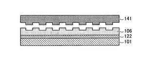
- FIG. 2 is a cross-sectional view schematically showing a multilayer structure in the manufacturing process of the cholesteric resin laminate 100 shown in FIG.
- FIG. 3 is a cross-sectional view schematically showing a multilayer structure in the manufacturing process of the cholesteric resin laminate 100 shown in FIG.
- FIG. 4 is a cross-sectional view schematically showing a multilayer structure in the manufacturing process of the cholesteric resin laminate 100 shown in FIG.
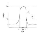
- FIG. 5 is a graph schematically showing an example of the measurement result of the spectral reflectance of the cholesteric resin layer and the calculation for obtaining the reflection band center wavelength based thereon.
- FIG. 1 is a cross-sectional view schematically showing an example of the cholesteric resin laminate of the present invention.
- FIG. 2 is a cross-sectional view schematically showing a multilayer structure in the manufacturing process of the cholesteric
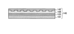
- FIG. 6 is a cross-sectional view schematically showing a process of manufacturing an example of the display medium of the present invention using the cholesteric resin laminate shown in FIG.
- FIG. 7 is a cross-sectional view schematically showing a process of manufacturing an example of the display medium of the present invention using the cholesteric resin laminate shown in FIG.
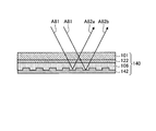
- FIG. 8 is a cross-sectional view schematically showing how the display medium 140 obtained in the manufacturing process shown in FIGS. 6 to 7 is used.
- (meth) acryl includes both acrylic and methacrylic.
- (Meth) acrylate includes both acrylate and methacrylate.
- (thio) epoxy includes both epoxy and thioepoxy.
- iso (thio) cyanate includes both isocyanate and isothiocyanate.
- the cholesteric resin laminate of the present invention includes a base material, an intermediate layer, and a cholesteric resin layer in this order.
- FIG. 1 is a cross-sectional view schematically showing an example of the cholesteric resin laminate of the present invention.
- a cholesteric resin laminate 100 includes a base material 101, a cholesteric resin layer 103, and an intermediate layer 122 interposed therebetween.
- the material which comprises a base material is not specifically limited, As an example, resin, a metal, glass, and paper are mentioned.
- a light transmissive material can be preferably used.
- the light transmissive material is preferably a material in which the total light transmittance of the substrate is 70% or more.
- the material constituting the base material is A material having a small degree of change in polarization of light transmitted through the substrate can be preferably used.
- Preferred examples of such materials include acetylcellulose resins and cycloolefin resins. From the viewpoint of easily obtaining the cost of acquisition and the affinity with the intermediate layer, acetylcellulose resin is more preferable.
- a more specific example of the acetyl cellulose resin includes a triacetyl cellulose resin.
- the base material 101 is a single layer made of a single material, but the base material in the present invention is not limited to this, and may be made up of a plurality of layers.
- the materials to be used may be the same as or different from each other. However, from the viewpoint of ease of production, a single layer is preferable.
- the thickness of the substrate is not particularly limited, and can be appropriately set according to the use of the cholesteric resin laminate.
- the thickness of the substrate is preferably 0.1 ⁇ m or more, more preferably 0.3 ⁇ m or more, while preferably 2000 ⁇ m or less, more preferably 1000 ⁇ m or less.
- Examples of the base material molding method include a melt molding method and a solution casting method.
- Examples of the melt molding method include a melt extrusion method in which molding is performed by melt extrusion, a press molding method, an inflation molding method, an injection molding method, a blow molding method, and a stretch molding method.
- the melt extrusion method, the inflation molding method, and the press molding method are preferable from the viewpoint of obtaining a base material before stretching excellent in mechanical strength and surface accuracy.
- the melt extrusion method is particularly preferable because the amount of the residual solvent can be reduced, and efficient and simple production is possible.
- a base material a commercial item can be obtained and used suitably.
- the surface of the base material may be subjected to surface treatment as necessary.
- the surface of the substrate on the side in contact with the intermediate layer can be subjected to a treatment such as a saponification treatment or a corona treatment prior to the formation of the intermediate layer.
- a treatment such as a saponification treatment or a corona treatment prior to the formation of the intermediate layer.
- the affinity with the intermediate layer can be increased.
- the cholesteric resin layer is a solid resin layer having cholesteric regularity.
- Cholesteric regularity means that the molecular axes are aligned in a certain direction on one plane, but the direction of the molecular axis is slightly offset in the next plane that overlaps it, and the angle is further shifted in the next plane. In this way, the structure is such that the molecular axes in the planes are displaced (twisted) as they sequentially pass through the overlapping planes. Thus, the structure in which the direction of the molecular axis is twisted becomes an optically chiral structure.
- the cholesteric resin layer usually has a circularly polarized light separation function. That is, it has a property of transmitting one circularly polarized light of right circularly polarized light and left circularly polarized light and reflecting a part or all of the other circularly polarized light. The reflection in the cholesteric resin layer reflects circularly polarized light while maintaining its chirality.
- the wavelength that exhibits the circularly polarized light separation function depends on the pitch of the helical structure in the cholesteric resin layer.
- the pitch of the helical structure is the distance in the plane normal direction until the angle of the molecular axis in the helical structure gradually shifts as it advances along the plane and then returns to the original molecular axis direction again.
- the wavelength at which the circularly polarized light separating function is exhibited can be changed.
- a circularly polarized light separating function over a wide band can be obtained by a single cholesteric resin layer.
- the cholesteric resin layer preferably has a circularly polarized light separating function for light in a part or all of the visible light wavelength region, and can selectively reflect circularly polarized light in the band.
- the cholesteric resin layer can be formed by applying a liquid crystal composition layer on a suitable support for forming a resin layer to form a liquid crystal composition layer and curing the layer.
- liquid crystal composition is a fluid material containing a liquid crystal compound.
- the material referred to as “liquid crystal composition” includes not only a mixture of two or more substances but also a material composed of a single substance.
- liquid crystalline compound a polymerizable liquid crystalline compound is preferable.
- a liquid crystal composition containing a polymerizable liquid crystal compound can be easily cured by polymerizing the liquid crystal compound.
- a cholesteric liquid crystal compound can be used as the liquid crystal compound.
- a cholesteric liquid crystalline compound is a compound that can exhibit cholesteric liquid crystallinity.
- a liquid crystal composition containing such a cholesteric liquid crystal compound when a layer of the liquid crystal composition is formed on the surface of the support, the liquid crystal compound exhibits a cholesteric liquid crystal phase in the layer, which is cured.
- a cholesteric resin layer can be produced.
- a non-liquid crystalline cholesteric resin layer cured with cholesteric regularity is obtained by polymerizing a liquid crystalline compound in a state exhibiting a cholesteric liquid crystal phase and curing the layer of the liquid crystal composition. Can do.
- liquid crystal composition capable of forming a cholesteric resin layer having a continuously changing helical pitch, as described above, include a compound represented by the following formula (1) and a specific rod-like liquid crystal And a liquid crystal composition containing a functional compound.
- this specific liquid crystal composition may be referred to as “liquid crystal composition (X)”.
- R 1 -A 1 -BA 2 -R 2 are each independently a linear or branched alkyl group having 1 to 20 carbon atoms, or a straight chain having 1 to 20 carbon atoms. Or a branched alkylene oxide group, a hydrogen atom, a halogen atom, a hydroxyl group, a carboxyl group, a (meth) acryl group, an epoxy group, a mercapto group, an isocyanate group, an amino group, which may be bonded with an arbitrary bonding group, And a group selected from the group consisting of a cyano group.
- the alkyl group and alkylene oxide group may be unsubstituted or substituted with one or more halogen atoms.
- the halogen atom, hydroxyl group, carboxyl group, (meth) acryl group, epoxy group, mercapto group, isocyanate group, amino group, and cyano group are an alkyl group having 1 to 2 carbon atoms, and an alkylene oxide. It may be bonded to a group.
- R 1 and R 2 include a halogen atom, a hydroxyl group, a carboxyl group, a (meth) acryl group, an epoxy group, a mercapto group, an isocyanate group, an amino group, and a cyano group.
- At least one of R 1 and R 2 is a reactive group.
- the compound represented by the formula (1) is fixed in the cholesteric resin layer at the time of curing, and a stronger layer can be formed.
- the reactive group include a carboxyl group, a (meth) acryl group, an epoxy group, a mercapto group, an isocyanate group, and an amino group.
- a 1 and A 2 are each independently 1,4-phenylene group, 1,4-cyclohexylene group, 1,4-cyclohexenyl group, 4,4′-biphenylene group, 4, A group selected from the group consisting of a 4′-bicyclohexylene group and a 2,6-naphthylene group.
- the 1,4-phenylene group, 1,4-cyclohexylene group, 1,4-cyclohexenyl group, 4,4′-biphenylene group, 4,4′-bicyclohexylene group, and 2,6-naphthylene group are Is not substituted, or is substituted by one or more substituents such as a halogen atom, a hydroxyl group, a carboxyl group, a cyano group, an amino group, an alkyl group having 1 to 10 carbon atoms, a halogenated alkyl group, etc. May be.
- substituents such as a halogen atom, a hydroxyl group, a carboxyl group, a cyano group, an amino group, an alkyl group having 1 to 10 carbon atoms, a halogenated alkyl group, etc. May be.
- substituents such as a halogen atom, a hydroxyl group, a carboxyl group, a cyan
- a 1 and A 2 include groups selected from the group consisting of 1,4-phenylene group, 4,4′-biphenylene group, and 2,6-naphthylene group. These aromatic ring skeletons are relatively rigid as compared with the alicyclic skeletons, have high affinity with the mesogen of the rod-like liquid crystal compound, and higher alignment uniformity.
- At least one of the compounds represented by the formula (1) preferably has liquid crystallinity, and preferably has chirality.
- the compound represented by the formula (1) is preferably used in combination of a plurality of optical isomers. For example, a mixture of a plurality of types of enantiomers, a mixture of a plurality of types of diastereomers, or a mixture of enantiomers and diastereomers may be used.
- At least one of the compounds represented by formula (1) preferably has a melting point in the range of 50 ° C to 150 ° C.
- the refractive index anisotropy ⁇ n is preferably high.
- the refractive index anisotropy ⁇ n of a liquid crystal composition containing the compound can be improved, and circularly polarized light is reflected.
- a cholesteric resin layer having a wide possible wavelength range can be produced.
- the refractive index anisotropy ⁇ n of the compound represented by the formula (1) is preferably 0.18 or more, more preferably 0.22 or more. Although the refractive index anisotropy ⁇ n is preferably as large as possible, it is practically 0.35 or less.
- the refractive index anisotropy ⁇ n can be measured by the Senarmon method.
- the cured resin layer is extinguished using an optical microscope (ECLIPSE E600POL (transmission / reflection type) equipped with a sensitive color plate, ⁇ / 4 wavelength plate, Senarmon compensator, GIF filter 546 nm, manufactured by Nikon Corporation).
- particularly preferred compounds represented by the formula (1) include the following compounds (A1) to (A9). One of these may be used alone, or two or more of these may be used in combination at any ratio.
- a rod-like liquid crystal compound having at least two reactive groups in one molecule can be used.
- the rod-like liquid crystalline compound include a compound represented by the formula (2). R 3 -C 3 -D 3 -C 5 -MC 6 -D 4 -C 4 -R 4 Formula (2)
- R 3 and R 4 are reactive groups, each independently (meth) acryl group, (thio) epoxy group, oxetane group, thietanyl group, aziridinyl group, pyrrole group, vinyl group. , An allyl group, a fumarate group, a cinnamoyl group, an oxazoline group, a mercapto group, an iso (thio) cyanate group, an amino group, a hydroxyl group, a carboxyl group, and an alkoxysilyl group.
- a high strength cholesteric resin layer can be obtained when the liquid crystal composition is cured.
- a cholesteric resin layer having a pencil hardness (JIS K5400) and usually HB or higher, preferably H or higher can be obtained.
- JIS K5400 pencil hardness
- HB or higher preferably H or higher
- D 3 and D 4 are each independently a single bond, a linear or branched alkyl group having 1 to 20 carbon atoms, and 1 to 20 carbon atoms. Represents a group selected from the group consisting of a linear or branched alkylene oxide group.
- C 3 to C 6 are each independently a single bond, —O—, —S—, —SS—, —CO—, —CS—, —OCO—, —CH 2.
- M represents a mesogenic group.
- M is an azomethine group, azoxy group, phenyl group, biphenyl group, terphenyl group, naphthalene group, anthracene group, benzoic acid ester group, cyclohexanecarboxyl group, which may be unsubstituted or substituted.
- Skeletons are —O—, —S—, —SS—, —CO—, —CS—, —OCO—, —CH 2 —, —OCH 2 —, —CH ⁇ N—N ⁇ CH—.
- Examples of the substituent that the mesogenic group M may have include a halogen atom, an optionally substituted alkyl group having 1 to 10 carbon atoms, a cyano group, a nitro group, —O—R 5 , — O—C ( ⁇ O) —R 5 , —C ( ⁇ O) —O—R 5 , —O—C ( ⁇ O) —O—R 5 , —NR 5 —C ( ⁇ O) —R 5 , —C ( ⁇ O) —NR 5 R 7 , or —O—C ( ⁇ O) —NR 5 R 7 may be mentioned.
- R 5 and R 7 represent a hydrogen atom or an alkyl group having 1 to 10 carbon atoms.
- the alkyl group includes —O—, —S—, —O—C ( ⁇ O) —, —C ( ⁇ O) —O—, —O—C. ( ⁇ O) —O—, —NR 6 —C ( ⁇ O) —, —C ( ⁇ O) —NR 6 —, —NR 6 —, or —C ( ⁇ O) — may be present. (However, the case where two or more of —O— and —S— are adjacent to each other is excluded).
- R 6 represents a hydrogen atom or an alkyl group having 1 to 6 carbon atoms.
- substituent in the “optionally substituted alkyl group having 1 to 10 carbon atoms” include, for example, a halogen atom, a hydroxyl group, a carboxyl group, a cyano group, an amino group, and a carbon atom number of 1 to 6 alkoxy groups, alkoxyalkoxy groups having 2 to 8 carbon atoms, alkoxyalkoxyalkoxy groups having 3 to 15 carbon atoms, alkoxycarbonyl groups having 2 to 7 carbon atoms, 2 carbon atoms A 7 to 7 alkylcarbonyloxy group, an alkoxycarbonyloxy group having 2 to 7 carbon atoms, and the like.
- the rod-like liquid crystalline compound preferably has an asymmetric structure.
- the asymmetric structure is a structure in which R 3 -C 3 -D 3 -C 5 -and -C 6 -D 4 -C 4 -R 4 are different in the formula (2) with the mesogenic group M as the center.
- R 3 -C 3 -D 3 -C 5 -and -C 6 -D 4 -C 4 -R 4 are different in the formula (2) with the mesogenic group M as the center.
- the refractive index anisotropy ⁇ n of the rod-like liquid crystal compound is preferably 0.18 or more, more preferably 0.22 or more. Although the refractive index anisotropy ⁇ n is preferably as large as possible, it is practically 0.35 or less. When a rod-like liquid crystalline compound having a refractive index anisotropy ⁇ n of 0.30 or more is used, the absorption edge on the long wavelength side of the ultraviolet absorption spectrum of the rod-like liquid crystalline compound may extend to the visible region. Can be used as long as they do not adversely affect the desired optical performance even in the visible range. By using such a rod-like liquid crystalline compound having a high refractive index anisotropy ⁇ n, a cholesteric resin layer having high optical performance (for example, selective reflection performance of circularly polarized light) can be obtained.
- rod-like liquid crystalline compound examples include the following compounds (B1) to (B9). Moreover, these may be used individually by 1 type and may be used combining two or more types by arbitrary ratios.
- the weight ratio represented by (total weight of compounds represented by formula (1)) / (total weight of rod-like liquid crystalline compounds) is preferably 0.05 or more, more preferably 0.1 or more, and particularly preferably 0. .15 or more, preferably 1 or less, more preferably 0.65 or less, and particularly preferably 0.45 or less.
- the refractive index anisotropy ⁇ n of the liquid crystal composition can be increased, for example, a cholesteric resin layer having desired optical performance such as selective reflection performance of circularly polarized light can be stably obtained.
- the total weight of the compound represented by the formula (1) indicates the weight when only one type of the compound represented by the formula (1) is used, and when two or more types are used. Indicates total weight.
- the total weight of the rod-like liquid crystalline compound indicates the weight when only one kind of rod-like liquid crystalline compound is used, and indicates the total weight when two or more kinds of rod-like liquid crystalline compounds are used.
- the molecular weight of the compound represented by Formula (1) is less than 600, and the molecular weight of a rod-shaped liquid crystalline compound is It is preferable that it is 600 or more.
- the liquid crystal composition such as the liquid crystal composition (X) may contain a chiral agent.
- the twist direction of the cholesteric resin layer can be appropriately selected depending on the type and structure of the chiral agent to be used.
- Specific examples of the chiral agent include JP-A-2005-289881, JP-A-2004-115414, JP-A-2003-66214, JP-A-2003-313187, JP-A-2003-342219, JP-A-2003-342219.
- 98/00428, Japanese Patent Laid-Open No. 2007-176870, etc. can be used as appropriate.
- it is available as LC756 of BASF Corporation Paliocolor.
- a chiral agent may be used individually by 1 type, and may be used combining two or more types by arbitrary ratios.
- the amount of the chiral agent can be arbitrarily set within a range not deteriorating the desired optical performance.
- the specific amount of the chiral agent is usually 1% by weight to 60% by weight in the liquid crystal composition.
- the cholesteric resin layer is preferably a compound layer having a crosslinked structure in order to improve its mechanical strength and durability.
- the liquid crystal composition such as the liquid crystal composition (X) may contain a crosslinking agent.
- the cross-linking agent increases the cross-linking density of the cholesteric resin layer by, for example, reacting when the liquid crystal composition layer is cured, promoting the reaction by heat treatment after curing, or allowing the reaction to proceed spontaneously due to moisture. be able to.
- a crosslinking agent what can react with an ultraviolet-ray, a heat
- a crosslinking agent what does not worsen the alignment uniformity of a liquid crystalline compound is preferable.
- crosslinking agent examples include trimethylolpropane tri (meth) acrylate, pentaerythritol tri (meth) acrylate, pentaerythritol tetra (meth) acrylate, dipentaerythritol hexa (meth) acrylate, and 2- (2-vinyloxyethoxy).
- Polyfunctional acrylate compounds such as ethyl acrylate; epoxy compounds such as glycidyl (meth) acrylate, ethylene glycol diglycidyl ether, glycerin triglycidyl ether, pentaerythritol tetraglycidyl ether; 2,2-bishydroxymethylbutanol-tris [3- ( 1-aziridinyl) propionate], 4,4-bis (ethyleneiminocarbonylamino) diphenylmethane, trimethylolpropane-tri- ⁇ -aziridinylpro Aziridine compounds such as pionate; isocyanate compounds such as isocyanurate type isocyanate, biuret type isocyanate and adduct type isocyanate derived from hexamethylene diisocyanate, hexamethylene diisocyanate; polyoxazoline compound having an oxazoline group in the side chain; vinyltrimethoxysilane; N-
- a crosslinking agent may be used individually by 1 type, and may be used combining two or more types by arbitrary ratios. Furthermore, you may use a well-known catalyst according to the reactivity of a crosslinking agent. By using a catalyst, productivity can be improved in addition to improvement in strength and durability of the cholesteric resin layer.
- the amount of the crosslinking agent is preferably such that the amount of the crosslinking agent in the cholesteric resin layer obtained by curing the layer of the liquid crystal composition is 0.1 wt% to 15 wt%.
- the liquid crystal composition such as the liquid crystal composition (X) may contain a photopolymerization initiator.
- a photoinitiator the compound which can generate
- photopolymerization initiator examples include benzoin, benzylmethyl ketal, benzophenone, biacetyl, acetophenone, Michler's ketone, benzyl, benzylisobutyl ether, tetramethylthiuram mono (di) sulfide, 2,2-azobisisobutyronitrile, 2,2-azobis-2,4-dimethylvaleronitrile, benzoyl peroxide, di-tert-butyl peroxide, 1-hydroxycyclohexyl phenyl ketone, 2-hydroxy-2-methyl-1-phenyl-propan-1-one 1- (4-Isopropylphenyl) -2-hydroxy-2-methylpropan-1-one, thioxanthone, 2-chlorothioxanthone, 2-methylthioxanthone, 2,4-diethylthioxanthone, methylbenzoylforme 2,2-diethoxyacetophenone, ⁇
- these may be used individually by 1 type and may be used combining two or more types by arbitrary ratios. Furthermore, you may control sclerosis
- the amount of the photopolymerization initiator is preferably 0.03% to 7% by weight in the liquid crystal composition. Since the degree of polymerization can be increased by setting the amount of the photopolymerization initiator to be equal to or higher than the lower limit of the above range, the mechanical strength of the cholesteric resin layer can be increased. Moreover, since the orientation of a liquid crystalline compound can be made favorable by setting it to the upper limit value or less, the liquid crystal phase of the liquid crystal composition can be stabilized.
- the liquid crystal composition such as the liquid crystal composition (X) may contain a surfactant.
- a surfactant for example, one that does not inhibit the orientation can be appropriately selected and used.
- a surfactant for example, a nonionic surfactant containing a siloxane or a fluorinated alkyl group in the hydrophobic group portion is preferably exemplified.
- oligomers having two or more hydrophobic group moieties in one molecule are particularly suitable.
- surfactants include PolyFox PF-151N, PF-636, PF-6320, PF-656, PF-6520, PF-3320, PF-651, PF-652 from OMNOVA; Neos FTX-209F, FTX-208G, FTX-204D of Surfactant, KH-40 of Surflon of Seimi Chemical Co., etc. can be used.
- surfactant may be used individually by 1 type and may be used combining two or more types by arbitrary ratios.
- the amount of the surfactant is preferably such that the amount of the surfactant in the cholesteric resin layer is 0.05% by weight to 3% by weight.
- the liquid crystal composition such as the liquid crystal composition (X) may further contain an optional component as necessary.
- optional components include a solvent; a polymerization inhibitor for improving pot life; an antioxidant, an ultraviolet absorber and a light stabilizer for improving durability; and the like.
- these arbitrary components may be used individually by 1 type, and may be used combining two or more types by arbitrary ratios. The amount of these optional components can be arbitrarily set within a range that does not deteriorate the desired optical performance.
- the method for producing the liquid crystal composition used in the present invention is not particularly limited, and the liquid crystal composition can be produced by mixing the above components.
- a liquid crystal composition such as the liquid crystal composition (X) described above is coated on a suitable support for forming a cholesteric resin layer to form a layer of the liquid crystal composition, and this layer is cured, whereby the cholesteric resin Layers can be formed.
- the support is not particularly limited, and any single-layer or multi-layer film suitable for carrying out the method can be used.
- support materials include cycloaliphatic olefin polymers, chain olefin polymers such as polyethylene and polypropylene, triacetyl cellulose, polyvinyl alcohol, polyimide, polyarylate, polyester, polycarbonate, polysulfone, polyethersulfone, and modified acrylic polymers.
- Synthetic resins such as epoxy resin, polystyrene, and acrylic resin.
- polyesters such as polyethylene terephthalate are preferable because they are easily available.
- the surface of the support Prior to the application of the liquid crystal composition, the surface of the support can be subjected to a treatment for imparting alignment regulating force.
- a treatment for imparting alignment regulating force examples include rubbing treatment of the support surface, stretching treatment of the support film, and the like.
- the support may have an alignment film on its surface, but preferably does not have an alignment film.
- the surface of the film formed of the above-described material is directly subjected to a treatment such as a rubbing treatment that imparts alignment regulating force, and the liquid crystal composition is applied.
- the material constituting the alignment film is usually a material that is more brittle than the material of the film described above. Therefore, when a support having an alignment film is used, the alignment is performed by applying an alignment regulating force such as rubbing. The film may be scraped to generate fine particles, which may cause defects.
- the liquid crystal composition can be applied by a known application method.
- the application method include an extrusion coating method, a direct gravure coating method, a reverse gravure coating method, a die coating method, and a bar coating method.
- an alignment treatment may be performed as necessary before performing the curing step.
- the alignment treatment can be performed, for example, by heating the liquid crystal composition layer at 50 to 150 ° C. for 0.5 to 10 minutes. By performing the alignment treatment, the liquid crystal compound in the liquid crystal composition can be aligned well.
- the curing treatment of the liquid crystal composition layer can be performed by a combination of one or more energy beam irradiations and a heating treatment.
- the heating conditions may be, for example, a temperature of 40 to 200 ° C., preferably 50 to 200 ° C., more preferably 50 to 140 ° C., and a time of 1 second to 3 minutes, preferably 5 to 120 seconds.
- energy rays include ultraviolet rays, visible light, and other electromagnetic waves.
- the energy beam irradiation can be performed, for example, by irradiating light having a wavelength of 200 to 500 nm for 0.01 second to 3 minutes.
- a cholesteric with a wide reflection band in which the pitch of the helical structure is continuously changed by repeatedly repeating weak UV irradiation of 0.01 to 50 mJ / cm 2 and heating a plurality of times alternately.
- a resin layer can be obtained.
- a relatively strong ultraviolet ray of 50 to 10,000 mJ / cm 2 is irradiated to completely polymerize the liquid crystalline compound to form a cholesteric resin layer. it can.
- the expansion of the reflection band and the irradiation with strong ultraviolet rays may be performed in the air, or a part or all of the process may be performed in an atmosphere in which the oxygen concentration is controlled (for example, in a nitrogen atmosphere). .
- the liquid crystalline compound when embossing is performed on the surface after forming the cholesteric resin layer, the liquid crystalline compound is not completely polymerized at this time, and after the embossing, additional ultraviolet irradiation is performed, Can be completely polymerized.
- the step of applying and curing the cholesteric liquid crystal composition on another layer such as an alignment film is not limited to one time, and the coating and curing are repeated a plurality of times to form two or more cholesteric resin layers. You can also.
- a liquid crystal composition such as the liquid crystal composition (X)
- a well-oriented rod-like liquid crystal compound having an ⁇ n of 0.18 or more is included.
- a cholesteric resin layer having a thickness of 5 ⁇ m or more can be easily formed.
- the thickness of the cholesteric resin layer is preferably 0.1 ⁇ m or more and more preferably 1 ⁇ m or more for obtaining sufficient reflectance. Moreover, in order to obtain the transparency of the film, the thickness is preferably 20 ⁇ m or less, and more preferably 10 ⁇ m or less.
- the thickness of the cholesteric resin layer is the sum of the thicknesses of each layer when the display medium of the present invention has two or more layers, and the thickness when the cholesteric resin layer is one layer. Sure.
- the intermediate layer is interposed between the base material and the cholesteric resin layer, so that the color change with time during use of the cholesteric resin laminate can be reduced.
- the reason the following can be considered, for example.
- the cholesteric resin layer there may be a monomer component that is not polymerized, and when the cholesteric resin layer is heated when using the cholesteric resin laminate, the monomer component moves in the layer, Furthermore, it may move to another layer and its concentration may vary. When such a change occurs, the pitch of the helical structure in the cholesteric resin layer changes, and a shift of the reflection band center wavelength can occur.
- the intermediate layer is interposed between the base material and the cholesteric resin layer, the migration of the monomer component is suppressed, and thereby the color change with time during use of the cholesteric resin laminate can be reduced.
- the intermediate layer As a material constituting the intermediate layer, a material that intervenes between the base material and the cholesteric resin layer and can be bonded thereto can be appropriately selected.
- the intermediate layer is (i) or (ii) below.
- a cured layer of a material containing a modified polyvinyl alcohol compound and a curing agent as the intermediate layer in order to obtain a heating change value of the reflection band center wavelength that is not more than a predetermined value.
- the polyvinyl alcohol When polyvinyl alcohol is used as the material for the intermediate layer, the polyvinyl alcohol can be obtained by general hydrolysis of polyvinyl acetate. Therefore, in the present application, the polyvinyl alcohol includes those containing an acetoxy group (—OCOCH 3 ) obtained by such a production method.
- examples of the modified polyvinyl alcohol compound include those obtained by replacing the —OH group of polyvinyl alcohol with a substituent.
- the substituent examples include an acetoacetoxy group (—OCOCH 2 COCH 3 ), a quaternary ammonium chloride group (—NR 3 Cl, R is an alkyl group, and in each R, the number of carbon atoms is preferably 1-5, more preferably 1-3, even more preferably 1-2), sodium sulfonate group (—SO 3 Z, Z is an alkali metal such as Na), ethylene oxide group (— (CH 2 CH 2 O ) X— H, X is preferably 1 or more, more preferably 1), and combinations thereof.
- the modified polyvinyl alcohol compound may be a compound in which a part of —OH groups contained in a large number of molecules of polyvinyl alcohol are substituted, or a compound in which all are substituted.
- modified polyvinyl alcohol compound include those in which a part of —OH group of polyvinyl alcohol is substituted with acetoacetoxy group.
- a commercially available product for example, trade name “Gozenex Z TM” manufactured by Nippon Synthetic Chemical Co., Ltd. is available.
- a material capable of more firmly curing polyvinyl alcohol and / or a modified polyvinyl alcohol compound can be appropriately selected and used.
- the curing agent include a crosslinking agent that can react with polyvinyl alcohol and / or a modified polyvinyl alcohol compound to form a crosslinked structure.
- polyvinyl alcohol crosslinking agents include boric acid and metal alkoxy compounds such as titanium and zirconium.
- the crosslinking agent of the acetoacetoxy group-modified polyvinyl alcohol compound include amine compounds, methylol compounds, and metal salts such as zirconium.
- crosslinking agent As a crosslinking agent, a commercial product (for example, a product name “Safe” manufactured by Nippon Synthetic Chemical Co., Ltd. as a curing agent for a modified polyvinyl alcohol compound in which a part of —OH group of polyvinyl alcohol is substituted with acetoacetoxy group is used. Link SPM-01 “and” Safe Link SPM-02 ”) are available.
- curing agent an intermediate
- the intermediate layer can contain any material in addition to the materials described above.
- optional materials include ultraviolet absorbers, colorants, and antistatic agents.
- the ratio of these optional components in the intermediate layer can be appropriately adjusted within a range that does not excessively impair the effects of the present invention.
- the thickness of the intermediate layer is preferably 0.01 ⁇ m or more, more preferably 0.1 ⁇ m or more, while it is preferably 100 ⁇ m or less, more preferably 10 ⁇ m or less, and even more preferably 5 ⁇ m or less.
- the thickness of the intermediate layer is not less than the lower limit, discoloration of the cholesteric resin layer under a high temperature environment can be satisfactorily suppressed.
- the thickness of the intermediate layer is not more than the above upper limit, it is possible to suppress cracking or breakage of the base material or the cholesteric resin layer due to the difference in expansion amount of each layer in a high temperature environment.
- the cholesteric resin laminate of the present invention can be preferably produced by forming a base material and a cholesteric resin layer, and further forming an intermediate layer therebetween.
- the intermediate layer is an adhesive layer obtained by curing an adhesive. Therefore, the cholesteric resin laminate of the present invention can be produced by bonding the base material and the cholesteric resin layer using an adhesive.
- the cholesteric resin laminate of the present invention can be produced by superposing a base material and a cholesteric resin layer via an adhesive layer, and curing the adhesive layer to form an intermediate layer.
- the intermediate layer can be formed using the following adhesive (i).
- the intermediate layer can be formed using the following adhesive (i).
- Adhesive (i) A material containing polyvinyl alcohol, a modified polyvinyl alcohol compound or a mixture thereof.
- Adhesive (ii) A material containing polyvinyl alcohol, a modified polyvinyl alcohol compound or a mixture thereof, and a curing agent.
- the adhesive may contain any component in addition to the components of the adhesive (i) or (ii) described above.
- Specific examples of the adhesive component include the same materials as those for the intermediate layer described above.
- the adhesive may further contain a solvent.
- a solvent is not particularly limited, and a solvent suitable for dissolution of other components and use in a production process can be appropriately selected.
- the adhesive contains polyvinyl alcohol, a modified polyvinyl alcohol compound, or a mixture thereof, it is preferable to use water as a solvent suitable for dissolving them.
- the ratio of the solid content (ratio of components other than the solvent) in the adhesive can be appropriately adjusted to a range suitable for dissolution of other components and use in the production process, and preferably 0.1% by weight or more. Preferably it is 1 wt% or more, while preferably 10 wt% or less, more preferably 7 wt% or less.
- the ratio of the curing agent is preferably 1 part by weight or more, more preferably 5 parts per 100 parts by weight of the polyvinyl alcohol and / or modified polyvinyl alcohol compound. Part by weight, preferably 20 parts by weight or less, more preferably 10 parts by weight or less. When the ratio of the curing agent is within the above range, a strong effect can be achieved efficiently.
- FIGS. 2 to 4 are cross-sectional views schematically showing a multilayer structure in the manufacturing process of the cholesteric resin laminate 100 shown in FIG.
- a multilayer body 110 including a support 111 and a cholesteric resin layer 103 formed on the support 111 is prepared.
- an adhesive is applied on the surface 110 ⁇ / b> U on the cholesteric resin layer 103 side of the multilayer 110 to form a liquid-state adhesive layer 121.
- the base material 101 is overlaid on the adhesive layer 121, and (support 111) / (cholesteric resin layer 103) / (adhesive layer 121) / (base material 101).
- the liquid-state adhesive layer 121 is cured, and as shown in FIG. 4, a composite having a layer structure of (support 111) / (cholesteric resin layer 103) / (intermediate layer 122) / (base material 101) is formed. A layered product 130 is obtained. Furthermore, the cholesteric resin laminate 100 shown in FIG. 1 can be obtained by peeling the support 111 from the multilayer 130.
- the conditions for curing the adhesive can be appropriately set as appropriate for the adhesive to be used.
- the adhesive (i) when used as an adhesive, the laminate including the adhesive layer may be dried to volatilize all or part of the solvent in the adhesive and cure the adhesive. it can.
- the adhesive When the adhesive (ii) is used as the adhesive, the adhesive can be cured by processing under conditions suitable for the reaction of the curing agent. When the reaction of the curing agent is accelerated by heating, the adhesive can be cured by advancing reactions such as solvent volatilization and crosslinking reaction by the same drying treatment as in the case of the adhesive (i). Moreover, when the thing which hardens
- the difference in the reflection band center wavelength of the cholesteric resin layer before and after being heated at 130 ° C. for 8 hours is 50 nm or less.
- the central wavelength of the reflection band of the cholesteric resin layer can be obtained based on the measurement result obtained by measuring the spectral reflectance of the cholesteric resin layer.
- the spectral reflectance can be measured using a spectrophotometer (for example, product name “V-550” manufactured by JASCO Corporation).
- a spectrophotometer for example, product name “V-550” manufactured by JASCO Corporation.
- V-550 product name “V-550” manufactured by JASCO Corporation
- the spectral reflectance is usually obtained as a graph in which the horizontal axis represents the wavelength and the vertical axis represents the reflectance at the wavelength.
- the reflection band of the cholesteric resin layer is usually shown as a broad peak in such a graph.
- FIG. 5 is a graph schematically showing an example of the measurement result of the spectral reflectance of the cholesteric resin layer and the calculation for obtaining the reflection band center wavelength based on the measurement result.
- the measurement result of the spectral reflectance is indicated by a curve 51.
- the reflectance R30 that is 30% of the maximum value Rmax of the spectral reflectance is the level indicated by the line 52.
- the values on the horizontal axis at the intersection of the curve 51 and the line 52 are ⁇ 1 and ⁇ 2, and the average of these values is the reflection band center wavelength ⁇ s.
- the cholesteric resin laminate is heated at 130 ° C. for 8 hours, and the reflection band center wavelength ⁇ t after heating is similarly determined.
- the value of the difference ⁇ st is preferably 30 nm or less, more preferably 10 nm or less.
- the lower limit of the value of the difference ⁇ st is not particularly limited, and is ideally 0 nm.
- Such a cholesteric resin laminate having a small difference in reflection band center wavelength before and after heating can be obtained by appropriately selecting the material of the intermediate layer. Specifically, by using the intermediate layer (i) or the intermediate layer (ii) listed above, a cholesteric resin laminate having a small difference in the reflection band center wavelength before and after heating can be obtained.
- the cholesteric resin laminate has a circularly polarized light separating function in a wavelength band as wide as possible for visible light when used for applications such as display media and decorative materials. Specifically, it is preferable that the width of the reflection band indicated by ⁇ 2- ⁇ 1 is 50 nm or more in a state before heating.
- cholesteric resin laminate [7. (Use of cholesteric resin laminate)
- the use of the cholesteric resin laminate of the present invention is arbitrary, taking advantage of optical properties and design features such as color and gloss, and products such as reflective materials, authenticity-identifying display media, and decorative materials It can be used as a component of Among these, a reflecting material, a display medium, and a decorating material will be described below as the reflecting material, the display medium, and the decorating material of the present invention, respectively.
- the reflective material of the present invention includes the cholesteric resin laminate of the present invention. Specifically, the cholesteric resin laminate is cut into an appropriate size and can be used as a reflector as it is, and the cholesteric resin laminate is bonded to another member via an appropriate adhesive, thereby reflecting the reflector. May be configured.
- the use of the reflecting material is not particularly limited, and for example, a cholesteric resin layer having a reflection band in the infrared region or the ultraviolet region can be formed and used as an infrared reflecting material or an ultraviolet reflecting agent. Since the reflective material of the present invention includes the cholesteric resin laminate of the present invention, it can be suitably used in a high temperature use environment.
- the display medium of the present invention includes the cholesteric resin laminate of the present invention.
- Examples of the display medium include a medium provided on the surface of the article in order to display information on the surface of the article. More specific examples include anti-counterfeit display media and security display media that utilize the property that a laminate including a cholesteric resin layer cannot be easily duplicated.
- Examples of the anti-counterfeit display medium include a label for authenticity identification and a seal.
- Examples of the security display medium include authentication media such as gold vouchers, gift certificates, tickets, certificates, and security cards.
- the display medium of the present invention includes the cholesteric resin laminate in a form in which an image visually recognized differs depending on how to observe. Specific examples thereof will be described with reference to FIGS.
- FIG. 6 to 7 are cross-sectional views schematically showing a process for manufacturing an example of the display medium of the present invention using the cholesteric resin laminate shown in FIG.
- a display medium having hologram embossing and a base image and different in how they are viewed depending on the observation method is manufactured.
- an embossing die 141 is pressed against the surface of the cholesteric resin laminate 100 shown in FIG. 1 on the side of the cholesteric resin layer 103, thereby giving an uneven shape to the surface of the cholesteric resin layer 103.
- the concavo-convex cholesteric resin layer 106 is used.
- a display medium capable of displaying a hologram image can be obtained by providing a fine concavo-convex structure in which the concavo-convex shape functions as a diffraction grating when illuminated with light.
- a base image layer 142 is formed on the surface of the concavo-convex cholesteric resin layer 106.
- the formation of the base image layer can be performed using a known means such as printing, whereby a base image layer in which an image can be visually recognized when observed from the substrate 101 side can be formed.
- the display medium 140 provided with the base material 101, the intermediate layer 122, the concavo-convex cholesteric resin layer 106, and the base image layer 142 in this order can be obtained.
- an arbitrary layer such as an adhesive layer and an additional base material layer may be further formed on the surface of the base image layer 142, and the layer may be provided on the surface of the article.
- FIG. 8 is a cross-sectional view schematically showing how the display medium 140 obtained in the manufacturing process shown in FIGS. 6 to 7 is used.
- FIG. 8 when non-polarized light is incident on the surface of the display medium 140 on the substrate 101 side in the direction indicated by the arrow A81, in the reflection band of the concavo-convex cholesteric resin layer 106, right circularly polarized light and left circularly polarized light One is reflected by the concavo-convex cholesteric resin layer 106 and is emitted in a mode indicated by an arrow A82a.
- the remaining light is reflected on the surface of the underlying image layer 142 and is emitted in the manner indicated by the arrow A82b.
- the concavo-convex cholesteric resin layer 106 is a layer that selectively reflects right circularly polarized light
- an image formed by hologram embossing is observed when the display medium 140 is observed through a filter that transmits only right circularly polarized light.
- the display medium 140 is observed through a filter that transmits only the left circularly polarized light
- an image of the base image is observed. Therefore, when such an image difference is observed, it can be determined that the display medium is genuine having the components of the present invention, and when such an image difference is not observed, the display medium is It can be determined that the display medium is not authentic and has no configuration of the display medium of the present invention, which is created by electronic printing or the like.
- the decorating material of the present invention comprises the cholesteric resin laminate of the present invention. Specifically, the cholesteric resin laminate is cut into an appropriate size and can be used as a decoration material as it is, and the cholesteric resin laminate is bonded to another member via an appropriate adhesive, thereby You may comprise the material for decorating. Examples of articles to be decorated with the decorating material of the present invention include ornaments, stationery, furniture, automobiles (interior and exterior), home appliances, personal computers, cosmetic packages, and the like.
- the design effect obtained by the decorating material of the present invention is not particularly limited, and may be any that takes advantage of the appearance of the cholesteric resin layer.
- a metallic luster can be imparted without using a metal
- a metallic design effect can be obtained even in applications where the use of a metal is not preferred.
- hologram embossing can be formed on the cholesteric resin layer to obtain a design effect of the hologram.
- a polyester film manufactured by Toyobo Co., Ltd., Cosmo Shine A4100, film thickness 100 ⁇ m, having an easy adhesion treatment surface on one side
- a cholesteric liquid crystal composition was applied to the surface using a # 5 wire bar to form a liquid crystal composition layer.
- the layer is subjected to orientation treatment at 100 ° C.
- a multilayer product 1 having a layer structure of cholesteric resin layer 1) was obtained.
- the value of ⁇ 2- ⁇ 1 of the obtained multilayer product 1 was 102 nm.
- Example 1 As an adhesive for forming the intermediate layer, an aqueous solution 1 composed of 5% by weight of polyvinyl alcohol and 95% by weight of water was prepared. A saponified 40 ⁇ m thick triacetyl cellulose film was prepared as a substrate. An adhesive was applied to the surface of the multilayer 1 obtained in Production Example 1 on the cholesteric resin layer 1 side, and a base material was placed thereon to superimpose to obtain a multilayer. The multilayer was pressed through a laminator and then dried at 60 ° C. for 2 minutes to cure the adhesive layer to form an intermediate layer. As a result, a multilayer product having a layer structure of (support) / (cholesteric resin layer 1) / (intermediate layer) / (base material) was obtained.
- the support was peeled from the multilayer.
- This obtained the cholesteric resin laminated body 1 which has a layer structure of (cholesteric resin layer 1) / (intermediate layer) / (base material).
- the thickness of the intermediate layer was 0.9 ⁇ m.
- the color of the cholesteric resin layer 1 of the obtained cholesteric resin laminate 1 was a slightly reddish gold color.
- the central wavelength of the reflection band of the cholesteric resin layer 1 was 619 nm.
- the cholesteric resin laminate 1 was heat-treated at 130 ° C. for 8 hours, and then the color of the cholesteric resin layer 1 and the reflection band center wavelength were observed again.
- the color of the cholesteric resin layer 1 was gold, and the color change due to the heat treatment was evaluated as “slight”.
- the central wavelength of the reflection band was 591 nm.
- Example 2 As an adhesive for forming the intermediate layer, a modified polyvinyl alcohol compound (manufactured by Nippon Synthetic Chemical Industry, trade name “GOHSEX Z-200”, a part of the —OH group of polyvinyl alcohol substituted with an acetoacetoxy group) 5 An aqueous solution 2 consisting of wt% and water 95 wt% was prepared. A cholesteric resin laminate having a layer structure of (cholesteric resin layer 1) / (intermediate layer) / (base material) in the same manner as in Example 1 except that this aqueous solution 2 was used instead of the aqueous solution 1 as an adhesive. Body 2 was obtained. The thickness of the intermediate layer was 1.0 ⁇ m.
- the color of the cholesteric resin layer 1 of the obtained cholesteric resin laminate 2 was a slightly reddish gold color.
- the central wavelength of the reflection band of the cholesteric resin layer 1 was 620 nm.
- the cholesteric resin laminate 2 was heat-treated at 130 ° C. for 8 hours, and then the color of the cholesteric resin layer 1 and the reflection band center wavelength were observed again.
- the color of the cholesteric resin layer 1 was gold, and the color change due to the heat treatment was evaluated as “slight”.
- the reflection band center wavelength was 602 nm.
- Example 3 As an adhesive for forming the intermediate layer, a modified polyvinyl alcohol compound (manufactured by Nippon Synthetic Chemical Industry, trade name “GOHSEX Z-200”, a part of the —OH group of polyvinyl alcohol substituted with an acetoacetoxy group) 5 An aqueous solution 3 consisting of 4% by weight, a curing agent (made by Nippon Synthetic Chemical Industry, trade name “Safelink SPM-01”, 7% aqueous solution) and 91% by weight of water was prepared.
- a modified polyvinyl alcohol compound manufactured by Nippon Synthetic Chemical Industry, trade name “GOHSEX Z-200”, a part of the —OH group of polyvinyl alcohol substituted with an acetoacetoxy group
- An aqueous solution 3 consisting of 4% by weight, a curing agent (made by Nippon Synthetic Chemical Industry, trade name “Safelink SPM-01”, 7% aqueous solution) and 91% by weight of water was prepared.
- the thickness of the intermediate layer was 0.9 ⁇ m.
- the color of the cholesteric resin layer 1 of the obtained cholesteric resin laminate 3 was a slightly reddish gold color.
- the central wavelength of the reflection band of the cholesteric resin layer 1 was 618 nm.
- this cholesteric resin laminate 3 was heat-treated at 130 ° C. for 8 hours, and then the color of the cholesteric resin layer 1 and the reflection band center wavelength were observed again.
- the color of the cholesteric resin layer 1 was gold, and the change in color due to the heat treatment was evaluated as “none”.
- the reflection band center wavelength was 613 nm.
- Example 4 (Cholesteric resin layer 2) / (intermediate layer) / (base material) layer in the same manner as in Example 3 except that the multilayer material 2 obtained in Production Example 2 was used instead of the multilayer material 1.
- a cholesteric resin laminate 4 having a configuration was obtained.
- the thickness of the intermediate layer was 1.1 ⁇ m.
- the color of the cholesteric resin layer 2 of the obtained cholesteric resin laminate 4 was red.
- the central wavelength of the reflection band of the cholesteric resin layer 1 was 626 nm.
- this cholesteric resin laminate 4 was heat-treated at 130 ° C. for 8 hours, and then the color of the cholesteric resin layer 2 and the central wavelength of the reflection band were observed again.
- the color of the cholesteric resin layer 2 was red, and the change in color due to the heat treatment was evaluated as “none”.
- the reflection band center wavelength was 619 nm.
- this multilayer 1 was heat-treated at 130 ° C. for 8 hours, and then the color of the cholesteric resin layer 1 and the central wavelength of the reflection band were observed again.
- the color of the cholesteric resin layer 1 was changed to green, and the color change due to the heat treatment was evaluated as “large”.
- the reflection band center wavelength was 536 nm.
- the multilayer 2 was heat-treated at 130 ° C. for 8 hours, and then the color of the cholesteric resin layer 2 and the central wavelength of the reflection band were observed again.
- the color of the cholesteric resin layer 1 was changed to green, and the color change due to the heat treatment was evaluated as “large”.
- the reflection band center wavelength was 543 nm.
- an acrylate ultraviolet curable adhesive (Toa Gosei Chemical, Aronix LCR0634) was prepared. Further, a saponified triacetyl cellulose film having a thickness of 40 ⁇ m, similar to that used in Example 1, was prepared as a substrate. An adhesive was applied to the surface of the multilayer 1 obtained in Production Example 1 on the cholesteric resin layer 1 side, and a base material was placed thereon to superimpose to obtain a multilayer. After pressing the multilayer through a laminator, the adhesive was cured by irradiating the substrate side with 3000 mJ / cm 2 ultraviolet rays. Thereafter, the support was peeled from the multilayer.
- This obtained the cholesteric resin laminated body 5 which has a layer structure of (cholesteric resin layer 1) / (intermediate layer) / (base material).
- the thickness of the intermediate layer was 3.6 ⁇ m.
- the color of the cholesteric resin layer 1 of the obtained cholesteric resin laminate 5 was a slightly reddish gold color.
- the central wavelength of the reflection band of the cholesteric resin layer 1 was 619 nm.
- this cholesteric resin laminate 5 was heat-treated at 130 ° C. for 8 hours, and then the color of the cholesteric resin layer 1 and the central wavelength of the reflection band were observed again.
- the color of the cholesteric resin layer 1 was changed to green, and the color change due to the heat treatment was evaluated as “large”.
- the reflection band center wavelength was 534 nm.
- Comparative Example 4 (Cholesteric resin layer 2) / (intermediate layer) / (base material) layer as in Comparative Example 3, except that the multilayer material 2 obtained in Production Example 2 was used instead of the multilayer material 1.
- a cholesteric resin laminate 6 having a configuration was obtained. The thickness of the intermediate layer was 3.8 ⁇ m. The color of the cholesteric resin layer 2 of the obtained cholesteric laminate 6 was red. The central wavelength of the reflection band of the cholesteric resin layer 1 was 629 nm.
- this cholesteric resin laminate 6 was heat-treated at 130 ° C. for 8 hours, and then the color of the cholesteric resin layer 2 and the central wavelength of the reflection band were observed again. The color of the cholesteric resin layer 2 was changed to green, and the color change due to the heat treatment was evaluated as “large”.
- the central wavelength of the reflection band was 539 nm.
- a two-component epoxy adhesive made by Cemedine, No. 1500, consisting of a main agent and a curing agent
- a saponified triacetyl cellulose film having a thickness of 40 ⁇ m, similar to that used in Example 1 was prepared as a substrate.
- an adhesive in which the same amount of the main agent and the curing agent are mixed is applied, and a base material is placed thereon and stacked to form a multilayered product.
- the multilayer was pressurized through a laminator and then heat treated at 40 ° C. for 10 hours to cure the adhesive.
- the support was peeled from the multilayer.
- This obtained the cholesteric resin laminated body 7 which has a layer structure of (cholesteric resin layer 1) / (intermediate layer) / (base material).
- the thickness of the intermediate layer was about 10 ⁇ m.
- the color of the cholesteric resin layer 1 of the obtained cholesteric laminate 7 was a slightly reddish gold color.
- the central wavelength of the reflection band of the cholesteric resin layer 1 was 618 nm.
- this cholesteric resin laminate 7 was heat-treated at 130 ° C. for 8 hours, and then the color of the cholesteric resin layer 1 and the reflection band center wavelength were observed again.
- the color of the cholesteric resin layer 1 was changed to green, and the color change due to the heat treatment was evaluated as “large”.
- the reflection band center wavelength was 552 nm.
Abstract
Description
即ち、本発明によれば、下記〔1〕~〔11〕が提供される。 As a result of studying the present inventors to solve the above problems, the cholesteric resin laminate has a specific structure including an intermediate layer, and is configured so that the change in the reflection band center wavelength is a predetermined amount or less. The present invention was completed.
That is, according to the present invention, the following [1] to [11] are provided.
前記積層体を130℃において8時間加熱した前後における前記コレステリック樹脂層の反射帯域中心波長の差が50nm以下であるコレステリック樹脂積層体。
〔2〕 前記コレステリック樹脂層が可視光波長領域の一部または全部の帯域の光を反射する、〔1〕に記載の樹脂積層体。
〔3〕 前記コレステリック樹脂層が架橋構造を有する化合物の層である、〔1〕又は〔2〕に記載のコレステリック樹脂積層体。
〔4〕 前記コレステリック樹脂層が、式(2)で表される化合物を含有する液晶組成物から形成されたものである、〔1〕~〔3〕のいずれか1項に記載のコレステリック樹脂積層体:
R3-C3-D3-C5-M-C6-D4-C4-R4 式(2)
但し式(2)において、
R3及びR4は、それぞれ独立して、(メタ)アクリル基、(チオ)エポキシ基、オキセタン基、チエタニル基、アジリジニル基、ピロール基、ビニル基、アリル基、フマレート基、シンナモイル基、オキサゾリン基、メルカプト基、イソ(チオ)シアネート基、アミノ基、ヒドロキシル基、カルボキシル基、及びアルコキシシリル基からなる群より選択される基を表し、
D3及びD4は、それぞれ独立して、単結合、炭素原子数1個~20個の直鎖状又は分岐鎖状のアルキル基、及び炭素原子数1個~20個の直鎖状又は分岐鎖状のアルキレンオキサイド基からなる群より選択される基を表し、
C3~C6は、それぞれ独立して、単結合、-O-、-S-、-S-S-、-CO-、-CS-、-OCO-、-CH2-、-OCH2-、-CH=N-N=CH-、-NHCO-、-O-(C=O)-O-、-CH2-(C=O)-O-、及び-CH2O-(C=O)-からなる群より選択される基を表し、
Mは、非置換又は置換基を有していてもよい、アゾメチン類、アゾキシ類、フェニル類、ビフェニル類、ターフェニル類、ナフタレン類、アントラセン類、安息香酸エステル類、シクロヘキサンカルボン酸フェニルエステル類、シアノフェニルシクロヘキサン類、シアノ置換フェニルピリミジン類、アルコキシ置換フェニルピリミジン類、フェニルジオキサン類、トラン類、及びアルケニルシクロヘキシルベンゾニトリル類からなる群から選択された互いに同一又は異なる2個~4個の骨格が、-O-、-S-、-S-S-、-CO-、-CS-、-OCO-、-CH2-、-OCH2-、-CH=N-N=CH-、-NHCO-、-O-(C=O)-O-、-CH2-(C=O)-O-、及び-CH2O-(C=O)-からなる群より選択される結合基によって結合された基を表し、
前記Mが有しうる置換基は、ハロゲン原子、置換基を有してもよい炭素数1個~10個のアルキル基、シアノ基、ニトロ基、-O-R5、-O-C(=O)-R5、-C(=O)-O-R5、-O-C(=O)-O-R5、-NR5-C(=O)-R5、-C(=O)-NR5R7、または-O-C(=O)-NR5R7であり、R5及びR7は、水素原子又は炭素数1個~10個のアルキル基を表し、R5及びR7がアルキル基である場合、当該アルキル基には、-O-、-S-、-O-C(=O)-、-C(=O)-O-、-O-C(=O)-O-、-NR6-C(=O)-、-C(=O)-NR6-、-NR6-、または-C(=O)-が介在していてもよく(ただし、-O-および-S-がそれぞれ2以上隣接して介在する場合を除く。)、R6は、水素原子または炭素数1個~6個のアルキル基を表し、
前記置換基を有してもよい炭素数1個~10個のアルキル基における置換基は、ハロゲン原子、ヒドロキシル基、カルボキシル基、シアノ基、アミノ基、炭素原子数1個~6個のアルコキシ基、炭素原子数2個~8個のアルコキシアルコキシ基、炭素原子数3個~15個のアルコキシアルコキシアルコキシ基、炭素原子数2個~7個のアルコキシカルボニル基、炭素原子数2個~7個のアルキルカルボニルオキシ基、又は炭素原子数2~7個のアルコキシカルボニルオキシ基である。
〔5〕 前記基材がアセチルセルロース樹脂またはシクロオレフィン樹脂のフィルムである〔1〕~〔4〕のいずれか1項に記載のコレステリック樹脂積層体。
〔6〕 前記中間層がポリビニルアルコール、変性ポリビニルアルコール化合物若しくはこれらの混合物を含む層であるか、又は前記ポリビニルアルコール、前記変性ポリビニルアルコール化合物若しくはこれらの混合物と、硬化剤とを含む材料の硬化物の層である〔1〕~〔5〕のいずれか1項に記載のコレステリック樹脂積層体。
〔7〕 前記中間層が前記変性ポリビニルアルコール化合物と、硬化剤とを含む材料の硬化物の層である〔6〕に記載のコレステリック樹脂積層体。
〔8〕 前記中間層が接着剤を硬化させてなる接着層であり、前記基材及び前記コレステリック樹脂層が、前記接着層を介して接着されてなる〔1〕~〔7〕のいずれか1項に記載のコレステリック樹脂積層体。
〔9〕 〔1〕~〔8〕のいずれか1項に記載のコレステリック樹脂積層体の製造方法であって、
基材及びコレステリック樹脂層を、接着剤の層を介して重ね合わせ、
前記接着剤の層を硬化させ中間層を形成する
ことを含む製造方法。
〔10〕 前記接着剤が、ポリビニルアルコール、変性ポリビニルアルコール化合物若しくはこれらの混合物を含む材料であるか、又は前記ポリビニルアルコール、前記変性ポリビニルアルコール化合物若しくはこれらの混合物と、硬化剤とを含む材料である〔9〕に記載の製造方法。
〔11〕 前記接着剤が、前記変性ポリビニルアルコール化合物と、硬化剤とを含む材料である〔10〕に記載の製造方法。
〔12〕 〔1〕~〔8〕のいずれか1項に記載のコレステリック樹脂積層体を備える反射材。
〔13〕 〔1〕~〔8〕のいずれか1項に記載のコレステリック樹脂積層体を備える表示媒体。
〔14〕 〔1〕~〔8〕のいずれか1項に記載のコレステリック樹脂積層体を備える加飾用材料。 [1] A cholesteric resin laminate comprising a base material, an intermediate layer, and a cholesteric resin layer in this order,
A cholesteric resin laminate in which a difference in central wavelength of the reflection band of the cholesteric resin layer before and after the laminate is heated at 130 ° C. for 8 hours is 50 nm or less.
[2] The resin laminate according to [1], wherein the cholesteric resin layer reflects light in a part or all of the visible light wavelength region.
[3] The cholesteric resin laminate according to [1] or [2], wherein the cholesteric resin layer is a layer of a compound having a crosslinked structure.
[4] The cholesteric resin laminate according to any one of [1] to [3], wherein the cholesteric resin layer is formed from a liquid crystal composition containing a compound represented by the formula (2). body:
R 3 -C 3 -D 3 -C 5 -MC 6 -D 4 -C 4 -R 4 Formula (2)
However, in Formula (2),
R 3 and R 4 are each independently a (meth) acryl group, (thio) epoxy group, oxetane group, thietanyl group, aziridinyl group, pyrrole group, vinyl group, allyl group, fumarate group, cinnamoyl group, oxazoline group Represents a group selected from the group consisting of a mercapto group, an iso (thio) cyanate group, an amino group, a hydroxyl group, a carboxyl group, and an alkoxysilyl group;
D 3 and D 4 are each independently a single bond, a linear or branched alkyl group having 1 to 20 carbon atoms, and a linear or branched group having 1 to 20 carbon atoms. Represents a group selected from the group consisting of a chain alkylene oxide group,
C 3 to C 6 are each independently a single bond, —O—, —S—, —S—S—, —CO—, —CS—, —OCO—, —CH 2 —, —OCH 2 —. , -CH = N-N = CH -, - NHCO -, - O- (C = O) -O -, - CH 2 - (C = O) -O-, and -CH 2 O- (C = O )-Represents a group selected from the group consisting of:
M is an azomethine, azoxy, phenyl, biphenyl, terphenyl, naphthalene, anthracene, benzoic acid ester, cyclohexanecarboxylic acid phenyl ester, which may be unsubstituted or substituted. 2 to 4 skeletons identical or different from each other selected from the group consisting of cyanophenylcyclohexanes, cyano-substituted phenylpyrimidines, alkoxy-substituted phenylpyrimidines, phenyldioxanes, tolanes, and alkenylcyclohexylbenzonitriles, —O—, —S—, —S—S—, —CO—, —CS—, —OCO—, —CH 2 —, —OCH 2 —, —CH═N—N═CH—, —NHCO—, -O- (C = O) -O - , - CH 2 - (C = O) -O-, and -CH 2 O- (C = O) - selected from the group consisting of It represents a group bonded through the bonding group,
The substituent that M may have is a halogen atom, an optionally substituted alkyl group having 1 to 10 carbon atoms, a cyano group, a nitro group, —O—R 5 , —O—C (= O) —R 5 , —C (═O) —O—R 5 , —O—C (═O) —O—R 5 , —NR 5 —C (═O) —R 5 , —C (═O ) —NR 5 R 7 , or —O—C (═O) —NR 5 R 7 , wherein R 5 and R 7 represent a hydrogen atom or an alkyl group having 1 to 10 carbon atoms, R 5 and When R 7 is an alkyl group, the alkyl group includes —O—, —S—, —O—C (═O) —, —C (═O) —O—, —O—C (═O ) —O—, —NR 6 —C (═O) —, —C (═O) —NR 6 —, —NR 6 —, or —C (═O) — may be present (provided that When two or more —O— and —S— are adjacent to each other Except.), R 6 represents a hydrogen atom or a C 1 to 6 alkyl group having a carbon
The substituent in the alkyl group having 1 to 10 carbon atoms which may have a substituent is a halogen atom, a hydroxyl group, a carboxyl group, a cyano group, an amino group, or an alkoxy group having 1 to 6 carbon atoms. , An alkoxyalkoxy group having 2 to 8 carbon atoms, an alkoxyalkoxyalkoxy group having 3 to 15 carbon atoms, an alkoxycarbonyl group having 2 to 7 carbon atoms, an alkoxycarbonyl group having 2 to 7 carbon atoms, An alkylcarbonyloxy group or an alkoxycarbonyloxy group having 2 to 7 carbon atoms.
[5] The cholesteric resin laminate according to any one of [1] to [4], wherein the substrate is a film of an acetylcellulose resin or a cycloolefin resin.
[6] The intermediate layer is a layer containing polyvinyl alcohol, a modified polyvinyl alcohol compound or a mixture thereof, or a cured product of a material containing the polyvinyl alcohol, the modified polyvinyl alcohol compound or a mixture thereof, and a curing agent. The cholesteric resin laminate according to any one of [1] to [5], which is a layer of
[7] The cholesteric resin laminate according to [6], wherein the intermediate layer is a layer of a cured product of a material including the modified polyvinyl alcohol compound and a curing agent.
[8] The intermediate layer is an adhesive layer formed by curing an adhesive, and the base material and the cholesteric resin layer are bonded via the adhesive layer. Any one of [1] to [7] The cholesteric resin laminate according to Item.
[9] A method for producing a cholesteric resin laminate according to any one of [1] to [8],
The substrate and the cholesteric resin layer are overlapped via the adhesive layer,
A manufacturing method comprising curing the adhesive layer to form an intermediate layer.
[10] The adhesive is a material containing polyvinyl alcohol, a modified polyvinyl alcohol compound or a mixture thereof, or a material containing the polyvinyl alcohol, the modified polyvinyl alcohol compound or a mixture thereof, and a curing agent. [9] The production method according to [9].
[11] The production method according to [10], wherein the adhesive is a material containing the modified polyvinyl alcohol compound and a curing agent.
[12] A reflector comprising the cholesteric resin laminate according to any one of [1] to [8].
[13] A display medium comprising the cholesteric resin laminate according to any one of [1] to [8].
[14] A decorating material comprising the cholesteric resin laminate according to any one of [1] to [8].
本発明のコレステリック樹脂積層体は、基材、中間層、及びコレステリック樹脂層をこの順に備える。
図1は、本発明のコレステリック樹脂積層体の一例を概略的に示す断面図である。図1において、コレステリック樹脂積層体100は、基材101と、コレステリック樹脂層103と、その間に介在する中間層122とを備える。 [1. Overview of cholesteric resin laminates]
The cholesteric resin laminate of the present invention includes a base material, an intermediate layer, and a cholesteric resin layer in this order.
FIG. 1 is a cross-sectional view schematically showing an example of the cholesteric resin laminate of the present invention. In FIG. 1, a
基材を構成する材料は、特に限定されず、その例としては、樹脂、金属、ガラス、及び紙が挙げられる。
コレステリック樹脂積層体の使用の態様において、基材が、コレステリック樹脂層より視認者側に位置する場合は、光透過性の材料を好ましく用いうる。光透過性の材料は、好ましくは基材の全光線透過率が70%以上となる材料である。 [2. Base material〕
The material which comprises a base material is not specifically limited, As an example, resin, a metal, glass, and paper are mentioned.
In the aspect of use of the cholesteric resin laminate, when the substrate is located on the viewer side from the cholesteric resin layer, a light transmissive material can be preferably used. The light transmissive material is preferably a material in which the total light transmittance of the substrate is 70% or more.
コレステリック樹脂層は、コレステリック規則性を有する固体の樹脂の層である。コレステリック規則性とは、一平面上では分子軸が一定の方向に並んでいるが、それに重なる次の平面では分子軸の方向が少し角度をなしてずれ、さらに次の平面ではさらに角度がずれるというように、重なって配列している平面を順次透過して進むに従って当該平面中の分子軸の角度がずれて(ねじれて)いく構造である。このように分子軸の方向がねじれてゆく構造は光学的にカイラルな構造となる。 [3. (Cholesteric resin layer)
The cholesteric resin layer is a solid resin layer having cholesteric regularity. Cholesteric regularity means that the molecular axes are aligned in a certain direction on one plane, but the direction of the molecular axis is slightly offset in the next plane that overlaps it, and the angle is further shifted in the next plane. In this way, the structure is such that the molecular axes in the planes are displaced (twisted) as they sequentially pass through the overlapping planes. Thus, the structure in which the direction of the molecular axis is twisted becomes an optically chiral structure.
液晶組成物は、液晶性化合物を含む流体状の材料である。ここで便宜上「液晶組成物」と称する材料は、2以上の物質の混合物のみならず、単一の物質からなる材料をも包含する。 [3.1. Liquid crystal composition]
The liquid crystal composition is a fluid material containing a liquid crystal compound. Here, for convenience, the material referred to as “liquid crystal composition” includes not only a mixture of two or more substances but also a material composed of a single substance.
式(1)において、R1及びR2は、それぞれ独立して、炭素原子数1個~20個の直鎖状又は分岐鎖状のアルキル基、炭素原子数1個~20個の直鎖状又は分岐鎖状のアルキレンオキサイド基、水素原子、ハロゲン原子、ヒドロキシル基、カルボキシル基、任意の結合基が介在していてもよい(メタ)アクリル基、エポキシ基、メルカプト基、イソシアネート基、アミノ基、及びシアノ基からなる群より選択される基である。 R 1 -A 1 -BA 2 -R 2 (1)
In the formula (1), R 1 and R 2 are each independently a linear or branched alkyl group having 1 to 20 carbon atoms, or a straight chain having 1 to 20 carbon atoms. Or a branched alkylene oxide group, a hydrogen atom, a halogen atom, a hydroxyl group, a carboxyl group, a (meth) acryl group, an epoxy group, a mercapto group, an isocyanate group, an amino group, which may be bonded with an arbitrary bonding group, And a group selected from the group consisting of a cyano group.
Bとして特に好ましいものとしては、単結合、-O-(C=O)-及び-CH=N-N=CH-が挙げられる。 In the formula (1), B is a single bond, —O—, —S—, —SS—, —CO—, —CS—, —OCO—, —CH 2 —, —OCH 2 —, —CH. = N-N = CH -, - NHCO -, - O- (C = O) -O -, - CH 2 - (C = O) -O-, and -CH 2 O- (C = O) - from the Selected from the group consisting of
Particularly preferred examples of B include a single bond, —O— (C═O) —, and —CH═NN—CH—.

R3-C3-D3-C5-M-C6-D4-C4-R4 式(2) As the liquid crystal compound used in combination with the compound represented by the formula (1) in the liquid crystal composition (X), a rod-like liquid crystal compound having at least two reactive groups in one molecule can be used. Examples of the rod-like liquid crystalline compound include a compound represented by the formula (2).
R 3 -C 3 -D 3 -C 5 -MC 6 -D 4 -C 4 -R 4 Formula (2)

上に述べた液晶組成物(X)等の液晶組成物を、コレステリック樹脂層形成用の適切な支持体上に塗布して、液晶組成物の層とし、この層を硬化することにより、コレステリック樹脂層を形成しうる。 [3.2. Specific Method for Forming Cholesteric Resin Layer]
A liquid crystal composition such as the liquid crystal composition (X) described above is coated on a suitable support for forming a cholesteric resin layer to form a layer of the liquid crystal composition, and this layer is cured, whereby the cholesteric resin Layers can be formed.
本発明のコレステリック樹脂積層体は、基材及びコレステリック樹脂層の間に中間層が介在することにより、コレステリック樹脂積層体の使用中の色の経時変化を低減しうる。特定の理論に拘束されるものでは無いが、その理由としては、例えば以下のことが考えられる。コレステリック樹脂層中には、重合していない単量体成分が存在する場合があり、コレステリック樹脂積層体の使用に際してコレステリック樹脂層が加熱されると、かかる単量体成分が層内を移動し、さらには他の層へ移行し、その濃度が変動する場合がある。そのような変動が生じると、コレステリック樹脂層中のらせん構造のピッチが変動し、反射帯域中心波長のシフトが発生しうる。ここで、基材及びコレステリック樹脂層の間に中間層が介在することにより、かかる単量体成分の移行が抑制され、それによりコレステリック樹脂積層体の使用中の色の経時変化を低減しうる。 [4. (Middle layer)
In the cholesteric resin laminate of the present invention, the intermediate layer is interposed between the base material and the cholesteric resin layer, so that the color change with time during use of the cholesteric resin laminate can be reduced. Although it is not restrained by a specific theory, as the reason, the following can be considered, for example. In the cholesteric resin layer, there may be a monomer component that is not polymerized, and when the cholesteric resin layer is heated when using the cholesteric resin laminate, the monomer component moves in the layer, Furthermore, it may move to another layer and its concentration may vary. When such a change occurs, the pitch of the helical structure in the cholesteric resin layer changes, and a shift of the reflection band center wavelength can occur. Here, when the intermediate layer is interposed between the base material and the cholesteric resin layer, the migration of the monomer component is suppressed, and thereby the color change with time during use of the cholesteric resin laminate can be reduced.
中間層(i):ポリビニルアルコール、変性ポリビニルアルコール化合物若しくはこれらの混合物を含む層。
中間層(ii):ポリビニルアルコール、変性ポリビニルアルコール化合物若しくはこれらの混合物と、硬化剤とを含む材料の硬化物の層。
特に、中間層として、変性ポリビニルアルコール化合物と、硬化剤とを含む材料の硬化物の層を採用することが、所定以下の反射帯域中心波長の加熱変化の値を得る上で特に好ましい。 As a material constituting the intermediate layer, a material that intervenes between the base material and the cholesteric resin layer and can be bonded thereto can be appropriately selected. In a preferred embodiment, the intermediate layer is (i) or (ii) below.
Intermediate layer (i): a layer containing polyvinyl alcohol, a modified polyvinyl alcohol compound or a mixture thereof.
Intermediate layer (ii): A layer of a cured product of a material containing polyvinyl alcohol, a modified polyvinyl alcohol compound or a mixture thereof, and a curing agent.
In particular, it is particularly preferable to use a cured layer of a material containing a modified polyvinyl alcohol compound and a curing agent as the intermediate layer in order to obtain a heating change value of the reflection band center wavelength that is not more than a predetermined value.
中間層の材料として変性ポリビニルアルコール化合物が用いられる場合、かかる変性ポリビニルアルコール化合物の例としては、ポリビニルアルコールの-OH基を、置換基で置換したものが挙げられる。置換基の例としては、アセトアセトキシ基(-OCOCH2COCH3)、4級アンモニウム塩化物基(-NR3Cl、Rはアルキル基であって、各々のRにおいて独立に、炭素数は好ましくは1~5、より好ましくは1~3、さらにより好ましくは1~2)、スルホン酸ナトリウム基(-SO3Z、ZはNa等のアルカリ金属)、エチレンオキサイド基(-(CH2CH2O)X-H、Xは好ましくは1以上、より好ましくは1)、及びこれらの組み合わせが挙げられる。変性ポリビニルアルコール化合物は、一分子のポリビニルアルコールが多数有する-OH基の一部が置換されたものであってもよく、全部が置換されたものであってもよい。 When polyvinyl alcohol is used as the material for the intermediate layer, the polyvinyl alcohol can be obtained by general hydrolysis of polyvinyl acetate. Therefore, in the present application, the polyvinyl alcohol includes those containing an acetoxy group (—OCOCH 3 ) obtained by such a production method.
When a modified polyvinyl alcohol compound is used as the material for the intermediate layer, examples of the modified polyvinyl alcohol compound include those obtained by replacing the —OH group of polyvinyl alcohol with a substituent. Examples of the substituent include an acetoacetoxy group (—OCOCH 2 COCH 3 ), a quaternary ammonium chloride group (—NR 3 Cl, R is an alkyl group, and in each R, the number of carbon atoms is preferably 1-5, more preferably 1-3, even more preferably 1-2), sodium sulfonate group (—SO 3 Z, Z is an alkali metal such as Na), ethylene oxide group (— (CH 2 CH 2 O ) X— H, X is preferably 1 or more, more preferably 1), and combinations thereof. The modified polyvinyl alcohol compound may be a compound in which a part of —OH groups contained in a large number of molecules of polyvinyl alcohol are substituted, or a compound in which all are substituted.
本発明のコレステリック樹脂積層体は、基材及びコレステリック樹脂層を形成し、さらにこれらの間に中間層を形成することにより、好ましく製造しうる。
好ましい態様において、中間層は、接着剤を硬化させてなる接着層である。したがって、本発明のコレステリック樹脂積層体は、基材及びコレステリック樹脂層を、接着剤を用いて接着することにより製造しうる。具体的には、本発明のコレステリック樹脂積層体は、基材及びコレステリック樹脂層を、接着剤の層を介して重ね合わせ、接着剤の層を硬化させ中間層を形成することにより製造しうる。 [5. Method for producing cholesteric resin laminate / method for forming intermediate layer]
The cholesteric resin laminate of the present invention can be preferably produced by forming a base material and a cholesteric resin layer, and further forming an intermediate layer therebetween.
In a preferred embodiment, the intermediate layer is an adhesive layer obtained by curing an adhesive. Therefore, the cholesteric resin laminate of the present invention can be produced by bonding the base material and the cholesteric resin layer using an adhesive. Specifically, the cholesteric resin laminate of the present invention can be produced by superposing a base material and a cholesteric resin layer via an adhesive layer, and curing the adhesive layer to form an intermediate layer.
接着剤(i):ポリビニルアルコール、変性ポリビニルアルコール化合物若しくはこれらの混合物を含む材料。
接着剤(ii):ポリビニルアルコール、変性ポリビニルアルコール化合物若しくはこれらの混合物と、硬化剤とを含む材料。
特に、接着剤として、変性ポリビニルアルコール化合物と、硬化剤とを含む材料を用いることが、所定以下の反射帯域中心波長の加熱変化の値を得る上で特に好ましい。 When the intermediate layer is the intermediate layer (i), the intermediate layer can be formed using the following adhesive (i). When the intermediate layer is the intermediate layer (ii), the intermediate layer can be formed using the following adhesive (i).
Adhesive (i): A material containing polyvinyl alcohol, a modified polyvinyl alcohol compound or a mixture thereof.
Adhesive (ii): A material containing polyvinyl alcohol, a modified polyvinyl alcohol compound or a mixture thereof, and a curing agent.
In particular, it is particularly preferable to use a material containing a modified polyvinyl alcohol compound and a curing agent as the adhesive in order to obtain a heating change value of the reflection band center wavelength below a predetermined value.
例えば、接着剤として接着剤(i)を用いる場合、接着剤の層を含む積層体を乾燥処理することにより、接着剤中の溶媒の全部又は一部を揮発させ、接着剤を硬化させることができる。 The conditions for curing the adhesive can be appropriately set as appropriate for the adhesive to be used.
For example, when the adhesive (i) is used as an adhesive, the laminate including the adhesive layer may be dried to volatilize all or part of the solvent in the adhesive and cure the adhesive. it can.
本発明のコレステリック樹脂積層体は、130℃において8時間加熱した前後におけるコレステリック樹脂層の反射帯域中心波長の差が50nm以下である。 [6. Reflection band center wavelength)
In the cholesteric resin laminate of the present invention, the difference in the reflection band center wavelength of the cholesteric resin layer before and after being heated at 130 ° C. for 8 hours is 50 nm or less.
差Δλstの値は、好ましくは30nm以下、より好ましくは10nm以下である。差Δλstの値の下限は特に限定されず、理想的には0nmである。 Further, the cholesteric resin laminate is heated at 130 ° C. for 8 hours, and the reflection band center wavelength λt after heating is similarly determined. The difference Δλst between the reflection band center wavelengths before and after heating can be obtained by the equation Δλst = | λs−λt |.
The value of the difference Δλst is preferably 30 nm or less, more preferably 10 nm or less. The lower limit of the value of the difference Δλst is not particularly limited, and is ideally 0 nm.
本発明のコレステリック樹脂積層体の用途は任意であり、光学的性質及びそれによる色や光沢等の意匠的な特徴を生かし、反射材、真正性識別用表示媒体、加飾用の材料等の製品の構成要素として用いうる。これらのうち、反射材、表示媒体及び加飾用材料について、それぞれ本発明の反射材、表示媒体及び加飾用材料として、以下において説明する。 [7. (Use of cholesteric resin laminate)
The use of the cholesteric resin laminate of the present invention is arbitrary, taking advantage of optical properties and design features such as color and gloss, and products such as reflective materials, authenticity-identifying display media, and decorative materials It can be used as a component of Among these, a reflecting material, a display medium, and a decorating material will be described below as the reflecting material, the display medium, and the decorating material of the present invention, respectively.
本発明の反射材は、前記本発明のコレステリック樹脂積層体を備える。具体的には、コレステリック樹脂積層体を適当な寸法に裁断し、そのまま反射材として用いうる他、コレステリック樹脂積層体を、適当な接着剤を介して他の部材に貼合し、それにより反射材を構成してもよい。反射材の用途は、特に限定されず、例えば、コレステリック樹脂層として赤外領域又は紫外領域に反射帯域を有するものを形成し、それを用いて赤外線反射材又は紫外線反射剤としうる。本発明の反射材は、前記本発明のコレステリック樹脂積層体を備えるため、高温の使用環境下において好適に用いうる。 [7.1. (Reflective material)
The reflective material of the present invention includes the cholesteric resin laminate of the present invention. Specifically, the cholesteric resin laminate is cut into an appropriate size and can be used as a reflector as it is, and the cholesteric resin laminate is bonded to another member via an appropriate adhesive, thereby reflecting the reflector. May be configured. The use of the reflecting material is not particularly limited, and for example, a cholesteric resin layer having a reflection band in the infrared region or the ultraviolet region can be formed and used as an infrared reflecting material or an ultraviolet reflecting agent. Since the reflective material of the present invention includes the cholesteric resin laminate of the present invention, it can be suitably used in a high temperature use environment.
本発明の表示媒体は前記本発明のコレステリック樹脂積層体を備える。
表示媒体の例としては、物品の表面に情報を表示するために、物品の表面に設ける媒体が挙げられる。より具体的な例としては、コレステリック樹脂層を含む積層体が容易に複製できない性質を利用した、偽造防止用表示媒体、及びセキュリティ用表示媒体が挙げられる。偽造防止用表示媒体としては、例えば、真正性識別用のラベル、シールなどが挙げられる。セキュリティ用表示媒体としては、例えば、金券、商品券、チケット、証明書、セキュリティカード等の認証媒体等が挙げられる。 [7.2. Display media]
The display medium of the present invention includes the cholesteric resin laminate of the present invention.
Examples of the display medium include a medium provided on the surface of the article in order to display information on the surface of the article. More specific examples include anti-counterfeit display media and security display media that utilize the property that a laminate including a cholesteric resin layer cannot be easily duplicated. Examples of the anti-counterfeit display medium include a label for authenticity identification and a seal. Examples of the security display medium include authentication media such as gold vouchers, gift certificates, tickets, certificates, and security cards.
本発明の加飾用材料は前記本発明のコレステリック樹脂積層体を備える。具体的には、コレステリック樹脂積層体を適当な寸法に裁断し、そのまま加飾用材料として用いうる他、コレステリック樹脂積層体を、適当な接着剤を介して他の部材に貼合し、それにより加飾用材料を構成してもよい。本発明の加飾用材料による加飾の対象となる物品としては、例えば、装飾品、文具、家具、自動車(内外装)、家電、パーソナルコンピューター、化粧品パッケージ等が挙げられる。本発明の加飾用材料により得る意匠的な効果は特に限定されず、コレステリック樹脂層の持つ外観を生かした任意のものとしうる。例えば、金属を用いずに金属調の光沢を付与することができるので、金属の使用が好ましくない用途においても金属調の意匠的効果を得ることができる。また、上に述べた表示媒体と同様に、コレステリック樹脂層上にホログラムエンボスを形成し、ホログラムの意匠的効果を得ることもできる。 [7.3. Decorative materials)
The decorating material of the present invention comprises the cholesteric resin laminate of the present invention. Specifically, the cholesteric resin laminate is cut into an appropriate size and can be used as a decoration material as it is, and the cholesteric resin laminate is bonded to another member via an appropriate adhesive, thereby You may comprise the material for decorating. Examples of articles to be decorated with the decorating material of the present invention include ornaments, stationery, furniture, automobiles (interior and exterior), home appliances, personal computers, cosmetic packages, and the like. The design effect obtained by the decorating material of the present invention is not particularly limited, and may be any that takes advantage of the appearance of the cholesteric resin layer. For example, since a metallic luster can be imparted without using a metal, a metallic design effect can be obtained even in applications where the use of a metal is not preferred. Similarly to the display medium described above, hologram embossing can be formed on the cholesteric resin layer to obtain a design effect of the hologram.
以下の操作は、別に断らない限り、常温常圧大気中にて行った。 In the following description, “%” and “part” representing amounts are based on weight unless otherwise specified.
The following operations were performed in a normal temperature and normal pressure atmosphere unless otherwise specified.
〔反射帯域中心波長〕
実施例及び比較例で作製したコレステリック樹脂積層体の分光反射率を、分光光度計(日本分光(株)製、製品名「V-550」)を用いて行った。得られた分光反射率のグラフにおいて、最大の反射率Rmaxの30%の反射率を示す2つの波長のうちの短波長側の波長λ1及び長波長側の波長λ2から、式λs=(λ1+λ2)/2により、反射帯域中心波長を求めた。 〔Evaluation methods〕
[Reflection band center wavelength]
The spectral reflectances of the cholesteric resin laminates produced in the examples and comparative examples were measured using a spectrophotometer (product name “V-550” manufactured by JASCO Corporation). In the obtained spectral reflectance graph, from the wavelength λ1 on the short wavelength side and the wavelength λ2 on the long wavelength side of the two wavelengths showing the reflectance of 30% of the maximum reflectance Rmax, the formula λs = (λ1 + λ2) The center wavelength of the reflection band was obtained from / 2.
コレステリック樹脂層の色は、白色蛍光灯の照明下で、コレステリック樹脂層表面の法線方向から目視観察することにより評価した。
加熱処理による色の変化は、加熱処理前後で色の変化が認識できない場合は「なし」、色の変化があったが変化後の色が変化後の色と同系統の色であった場合は「わずか」、それ以外の色の変化があった場合は「大」と評価した。 [Color of cholesteric resin layer and its change]
The color of the cholesteric resin layer was evaluated by visual observation from the normal direction of the surface of the cholesteric resin layer under illumination of a white fluorescent lamp.
The color change due to the heat treatment is `` None '' when the color change cannot be recognized before and after the heat treatment, and there is a color change but the changed color is the same color as the changed color “Slightly”, and any other color change was evaluated as “large”.
表1に示す配合割合で各成分を混合して、コレステリック液晶組成物を調製した。
表1中の化合物(1)及び(2)は、それぞれ下記の構造を有する化合物である。化合物(1)は国際公開第WO2009/041512号に、また化合物(2)は特開平11-100575号公報に記載された方法に従い製造したものを使用した。 (Production Example 1: Cholesteric resin layer 1)
Cholesteric liquid crystal compositions were prepared by mixing the components at the blending ratios shown in Table 1.
Compounds (1) and (2) in Table 1 are compounds having the following structures, respectively. Compound (1) was prepared according to the method described in International Publication No. WO2009 / 041512, and Compound (2) was prepared according to the method described in JP-A-11-10055.


コレステリック液晶組成物の配合割合を表1に示す通り変更した他は、製造例1と同様にして、支持体上に厚み1.0μmのコレステリック樹脂層2を形成し、(支持体)/(コレステリック樹脂層2)の層構成を有する複層物2を得た。得られた複層物2のλ2-λ1の値は63nmであった。 (Production Example 2: Cholesteric resin layer 2)
A cholesteric resin layer 2 having a thickness of 1.0 μm was formed on a support in the same manner as in Production Example 1, except that the blending ratio of the cholesteric liquid crystal composition was changed as shown in Table 1, and (support) / (cholesteric) A multilayer body 2 having the layer structure of the resin layer 2) was obtained. The value of λ2-λ1 of the obtained multilayer product 2 was 63 nm.

中間層を形成するための接着剤として、ポリビニルアルコール5重量%及び水95重量%からなる水溶液1を用意した。また、基材として、鹸化処理した厚み40μmのトリアセチルセルロースフィルムを用意した。
製造例1で得られた複層物1のコレステリック樹脂層1側の表面に、接着剤を塗布し、その上に基材を載せて重ね合わせ、複層物を得た。この複層物をラミネーターに通して加圧した後、60℃で2分間乾燥し、接着剤の層を硬化させて中間層とした。これにより、(支持体)/(コレステリック樹脂層1)/(中間層)/(基材)の層構成を有する複層物を得た。
その後、この複層物から、支持体を剥離した。これにより、(コレステリック樹脂層1)/(中間層)/(基材)の層構成を有するコレステリック樹脂積層体1を得た。中間層の厚みは0.9μmであった。
得られたコレステリック樹脂積層体1のコレステリック樹脂層1の色は、わずかに赤みかかった金色であった。コレステリック樹脂層1の反射帯域中心波長は619nmであった。 Example 1
As an adhesive for forming the intermediate layer, an aqueous solution 1 composed of 5% by weight of polyvinyl alcohol and 95% by weight of water was prepared. A saponified 40 μm thick triacetyl cellulose film was prepared as a substrate.
An adhesive was applied to the surface of the multilayer 1 obtained in Production Example 1 on the cholesteric resin layer 1 side, and a base material was placed thereon to superimpose to obtain a multilayer. The multilayer was pressed through a laminator and then dried at 60 ° C. for 2 minutes to cure the adhesive layer to form an intermediate layer. As a result, a multilayer product having a layer structure of (support) / (cholesteric resin layer 1) / (intermediate layer) / (base material) was obtained.
Thereafter, the support was peeled from the multilayer. This obtained the cholesteric resin laminated body 1 which has a layer structure of (cholesteric resin layer 1) / (intermediate layer) / (base material). The thickness of the intermediate layer was 0.9 μm.
The color of the cholesteric resin layer 1 of the obtained cholesteric resin laminate 1 was a slightly reddish gold color. The central wavelength of the reflection band of the cholesteric resin layer 1 was 619 nm.
中間層を形成するための接着剤として、変性ポリビニルアルコール化合物(日本合成化学工業製、商品名「ゴーセネックスZ-200」、ポリビニルアルコールの-OH基の一部をアセトアセトキシ基で置換したもの)5重量%及び水95重量%からなる水溶液2を用意した。接着剤として、水溶液1に代えてこの水溶液2を用いた他は、実施例1と同様にして、(コレステリック樹脂層1)/(中間層)/(基材)の層構成を有するコレステリック樹脂積層体2を得た。中間層の厚みは1.0μmであった。
得られたコレステリック樹脂積層体2のコレステリック樹脂層1の色は、わずかに赤みかかった金色であった。コレステリック樹脂層1の反射帯域中心波長は620nmであった。
次に、このコレステリック樹脂積層体2を130℃下で8時間加熱処理した後、再びコレステリック樹脂層1の色及び反射帯域中心波長を観察した。コレステリック樹脂層1の色は金色であり、加熱処理による色の変化は「わずか」と評価された。反射帯域中心波長は602nmであった。 (Example 2)
As an adhesive for forming the intermediate layer, a modified polyvinyl alcohol compound (manufactured by Nippon Synthetic Chemical Industry, trade name “GOHSEX Z-200”, a part of the —OH group of polyvinyl alcohol substituted with an acetoacetoxy group) 5 An aqueous solution 2 consisting of wt% and water 95 wt% was prepared. A cholesteric resin laminate having a layer structure of (cholesteric resin layer 1) / (intermediate layer) / (base material) in the same manner as in Example 1 except that this aqueous solution 2 was used instead of the aqueous solution 1 as an adhesive. Body 2 was obtained. The thickness of the intermediate layer was 1.0 μm.
The color of the cholesteric resin layer 1 of the obtained cholesteric resin laminate 2 was a slightly reddish gold color. The central wavelength of the reflection band of the cholesteric resin layer 1 was 620 nm.
Next, the cholesteric resin laminate 2 was heat-treated at 130 ° C. for 8 hours, and then the color of the cholesteric resin layer 1 and the reflection band center wavelength were observed again. The color of the cholesteric resin layer 1 was gold, and the color change due to the heat treatment was evaluated as “slight”. The reflection band center wavelength was 602 nm.
中間層を形成するための接着剤として、変性ポリビニルアルコール化合物(日本合成化学工業製、商品名「ゴーセネックスZ-200」、ポリビニルアルコールの-OH基の一部をアセトアセトキシ基で置換したもの)5重量%、硬化剤(日本合成化学工業製、商品名「セーフリンクSPM-01」、7%水溶液)4重量%及び水91重量%からなる水溶液3を用意した。接着剤として、水溶液1に代えてこの水溶液3を用いた他は、実施例1と同様にして、(コレステリック樹脂層1)/(中間層)/(基材)の層構成を有するコレステリック樹脂積層体3を得た。中間層の厚みは0.9μmであった。
得られたコレステリック樹脂積層体3のコレステリック樹脂層1の色は、わずかに赤みかかった金色であった。コレステリック樹脂層1の反射帯域中心波長は618nmであった。 (Example 3)
As an adhesive for forming the intermediate layer, a modified polyvinyl alcohol compound (manufactured by Nippon Synthetic Chemical Industry, trade name “GOHSEX Z-200”, a part of the —OH group of polyvinyl alcohol substituted with an acetoacetoxy group) 5 An aqueous solution 3 consisting of 4% by weight, a curing agent (made by Nippon Synthetic Chemical Industry, trade name “Safelink SPM-01”, 7% aqueous solution) and 91% by weight of water was prepared. A cholesteric resin laminate having a layer structure of (cholesteric resin layer 1) / (intermediate layer) / (base material) in the same manner as in Example 1 except that this aqueous solution 3 was used instead of the aqueous solution 1 as an adhesive. Body 3 was obtained. The thickness of the intermediate layer was 0.9 μm.
The color of the cholesteric resin layer 1 of the obtained cholesteric resin laminate 3 was a slightly reddish gold color. The central wavelength of the reflection band of the cholesteric resin layer 1 was 618 nm.
複層物1の代わりに、製造例2で得た複層物2を使用した他は、実施例3と同様にして、(コレステリック樹脂層2)/(中間層)/(基材)の層構成を有するコレステリック樹脂積層体4を得た。中間層の厚みは1.1μmであった。
得られたコレステリック樹脂積層体4のコレステリック樹脂層2の色は、赤色であった。コレステリック樹脂層1の反射帯域中心波長は626nmであった。 Example 4
(Cholesteric resin layer 2) / (intermediate layer) / (base material) layer in the same manner as in Example 3 except that the multilayer material 2 obtained in Production Example 2 was used instead of the multilayer material 1. A cholesteric resin laminate 4 having a configuration was obtained. The thickness of the intermediate layer was 1.1 μm.
The color of the cholesteric resin layer 2 of the obtained cholesteric resin laminate 4 was red. The central wavelength of the reflection band of the cholesteric resin layer 1 was 626 nm.
製造例1で得られた(支持体)/(コレステリック樹脂層1)の層構成を有する複層物1をそのまま、実施例1~4で得られたコレステリック樹脂積層体と同様に評価した。複層物1のコレステリック樹脂層1の色は、わずかに赤みかかった金色であった。コレステリック樹脂層1の反射帯域中心波長は617nmであった。 (Comparative Example 1)
The multilayer 1 having the layer structure of (support) / (cholesteric resin layer 1) obtained in Production Example 1 was evaluated in the same manner as the cholesteric resin laminates obtained in Examples 1 to 4. The color of the cholesteric resin layer 1 of the multilayer 1 was a slightly reddish gold color. The central wavelength of the reflection band of the cholesteric resin layer 1 was 617 nm.
製造例2で得られた(支持体)/(コレステリック樹脂層2)の層構成を有する複層物2をそのまま、実施例1~4で得られたコレステリック樹脂積層体と同様に評価した。複層物2のコレステリック樹脂層2の色は、赤色であった。コレステリック樹脂層2の反射帯域中心波長は628nmであった。 (Comparative Example 2)
The multilayer body 2 having the layer structure of (support) / (cholesteric resin layer 2) obtained in Production Example 2 was evaluated as it was in the same manner as the cholesteric resin laminates obtained in Examples 1 to 4. The color of the cholesteric resin layer 2 of the multilayer body 2 was red. The reflection band center wavelength of the cholesteric resin layer 2 was 628 nm.
中間層を形成するための接着剤として、アクリレート系紫外線硬化型接着剤(東亜合成化学性、アロニックスLCR0634)を用意した。また、基材として、実施例1で用いたものと同様の、鹸化処理した厚み40μmのトリアセチルセルロースフィルムを用意した。
製造例1で得られた複層物1のコレステリック樹脂層1側の表面に、接着剤を塗布し、その上に基材を載せて重ね合わせ、複層物を得た。この複層物をラミネーターに通して加圧した後、基材側に3000mJ/cm2の紫外線を照射して、接着剤を硬化させた。
その後、この複層物から、支持体を剥離した。これにより、(コレステリック樹脂層1)/(中間層)/(基材)の層構成を有するコレステリック樹脂積層体5を得た。中間層の厚みは3.6μmであった。
得られたコレステリック樹脂積層体5のコレステリック樹脂層1の色は、わずかに赤みかかった金色であった。コレステリック樹脂層1の反射帯域中心波長は619nmであった。 (Comparative Example 3)
As an adhesive for forming the intermediate layer, an acrylate ultraviolet curable adhesive (Toa Gosei Chemical, Aronix LCR0634) was prepared. Further, a saponified triacetyl cellulose film having a thickness of 40 μm, similar to that used in Example 1, was prepared as a substrate.
An adhesive was applied to the surface of the multilayer 1 obtained in Production Example 1 on the cholesteric resin layer 1 side, and a base material was placed thereon to superimpose to obtain a multilayer. After pressing the multilayer through a laminator, the adhesive was cured by irradiating the substrate side with 3000 mJ / cm 2 ultraviolet rays.
Thereafter, the support was peeled from the multilayer. This obtained the cholesteric resin laminated body 5 which has a layer structure of (cholesteric resin layer 1) / (intermediate layer) / (base material). The thickness of the intermediate layer was 3.6 μm.
The color of the cholesteric resin layer 1 of the obtained cholesteric resin laminate 5 was a slightly reddish gold color. The central wavelength of the reflection band of the cholesteric resin layer 1 was 619 nm.
複層物1の代わりに、製造例2で得た複層物2を使用した他は、比較例3と同様にして、(コレステリック樹脂層2)/(中間層)/(基材)の層構成を有するコレステリック樹脂積層体6を得た。中間層の厚みは3.8μmであった。
得られたコレステリック積層体6のコレステリック樹脂層2の色は、赤色であった。コレステリック樹脂層1の反射帯域中心波長は629nmであった。
次に、このコレステリック樹脂積層体6を130℃下で8時間加熱処理した後、再びコレステリック樹脂層2の色及び反射帯域中心波長を観察した。コレステリック樹脂層2の色は緑色に変っており、加熱処理による色の変化は「大」と評価された。反射帯域中心波長は539nmであった。 (Comparative Example 4)
(Cholesteric resin layer 2) / (intermediate layer) / (base material) layer as in Comparative Example 3, except that the multilayer material 2 obtained in Production Example 2 was used instead of the multilayer material 1. A cholesteric resin laminate 6 having a configuration was obtained. The thickness of the intermediate layer was 3.8 μm.
The color of the cholesteric resin layer 2 of the obtained cholesteric laminate 6 was red. The central wavelength of the reflection band of the cholesteric resin layer 1 was 629 nm.
Next, this cholesteric resin laminate 6 was heat-treated at 130 ° C. for 8 hours, and then the color of the cholesteric resin layer 2 and the central wavelength of the reflection band were observed again. The color of the cholesteric resin layer 2 was changed to green, and the color change due to the heat treatment was evaluated as “large”. The central wavelength of the reflection band was 539 nm.
中間層を形成するための接着剤として、2液性エポキシ系接着剤(セメダイン製、1500番、主剤及び硬化剤からなる)を用意した。また、基材として、実施例1で用いたものと同様の、鹸化処理した厚み40μmのトリアセチルセルロースフィルムを用意した。
製造例1で得られた複層物1のコレステリック樹脂層1側の表面に、主剤と硬化剤を同量混合した接着剤を塗布し、その上に基材を載せて重ね合わせ、複層物を得た。この複層物をラミネーターに通して加圧した後、40℃下10時間加熱処理して、接着剤を硬化させた。
その後、この複層物から、支持体を剥離した。これにより、(コレステリック樹脂層1)/(中間層)/(基材)の層構成を有するコレステリック樹脂積層体7を得た。中間層の厚みは約10μmであった。
得られたコレステリック積層体7のコレステリック樹脂層1の色は、わずかに赤みかかった金色であった。コレステリック樹脂層1の反射帯域中心波長は618nmであった。 (Comparative Example 5)
As an adhesive for forming the intermediate layer, a two-component epoxy adhesive (made by Cemedine, No. 1500, consisting of a main agent and a curing agent) was prepared. Further, a saponified triacetyl cellulose film having a thickness of 40 μm, similar to that used in Example 1, was prepared as a substrate.
On the surface of the multilayered product 1 obtained in Production Example 1 on the cholesteric resin layer 1 side, an adhesive in which the same amount of the main agent and the curing agent are mixed is applied, and a base material is placed thereon and stacked to form a multilayered product. Got. The multilayer was pressurized through a laminator and then heat treated at 40 ° C. for 10 hours to cure the adhesive.
Thereafter, the support was peeled from the multilayer. This obtained the cholesteric resin laminated body 7 which has a layer structure of (cholesteric resin layer 1) / (intermediate layer) / (base material). The thickness of the intermediate layer was about 10 μm.
The color of the cholesteric resin layer 1 of the obtained cholesteric laminate 7 was a slightly reddish gold color. The central wavelength of the reflection band of the cholesteric resin layer 1 was 618 nm.


52:反射率R30の水準の線
100:コレステリック樹脂積層体
101:基材
103:コレステリック樹脂層
106:凹凸コレステリック樹脂層
110:複層物
110U:複層物の、コレステリック樹脂層側の表面
111:支持体
120:複層物
121:接着剤の層
122:中間層
130:複層物
140:表示媒体
141:エンボス型
142:下地画像層 51: Curve of measurement result of spectral reflectance 52: Line of level of reflectance R30 100: Cholesteric resin laminate 101: Base material 103: Cholesteric resin layer 106: Concave and convex cholesteric resin layer 110:
Claims (14)
- 基材、中間層、及びコレステリック樹脂層をこの順に備えるコレステリック樹脂積層体であって、
前記積層体を130℃において8時間加熱した前後における前記コレステリック樹脂層の反射帯域中心波長の差が50nm以下であるコレステリック樹脂積層体。 A cholesteric resin laminate comprising a base material, an intermediate layer, and a cholesteric resin layer in this order,
A cholesteric resin laminate in which a difference in central wavelength of the reflection band of the cholesteric resin layer before and after the laminate is heated at 130 ° C. for 8 hours is 50 nm or less. - 前記コレステリック樹脂層が可視光波長領域の一部または全部の帯域の光を反射する、請求項1に記載のコレステリック樹脂積層体。 The cholesteric resin laminate according to claim 1, wherein the cholesteric resin layer reflects light in a part or all of the visible light wavelength region.
- 前記コレステリック樹脂層が架橋構造を有する化合物の層である、請求項1又は2に記載のコレステリック樹脂積層体。 The cholesteric resin laminate according to claim 1 or 2, wherein the cholesteric resin layer is a layer of a compound having a crosslinked structure.
- 前記コレステリック樹脂層が、式(2)で表される化合物を含有する液晶組成物から形成されたものである、請求項1~3のいずれか1項に記載のコレステリック樹脂積層体:
R3-C3-D3-C5-M-C6-D4-C4-R4 式(2)
但し式(2)において、
R3及びR4は、それぞれ独立して、(メタ)アクリル基、(チオ)エポキシ基、オキセタン基、チエタニル基、アジリジニル基、ピロール基、ビニル基、アリル基、フマレート基、シンナモイル基、オキサゾリン基、メルカプト基、イソ(チオ)シアネート基、アミノ基、ヒドロキシル基、カルボキシル基、及びアルコキシシリル基からなる群より選択される基を表し、
D3及びD4は、それぞれ独立して、単結合、炭素原子数1個~20個の直鎖状又は分岐鎖状のアルキル基、及び炭素原子数1個~20個の直鎖状又は分岐鎖状のアルキレンオキサイド基からなる群より選択される基を表し、
C3~C6は、それぞれ独立して、単結合、-O-、-S-、-S-S-、-CO-、-CS-、-OCO-、-CH2-、-OCH2-、-CH=N-N=CH-、-NHCO-、-O-(C=O)-O-、-CH2-(C=O)-O-、及び-CH2O-(C=O)-からなる群より選択される基を表し、
Mは、非置換又は置換基を有していてもよい、アゾメチン類、アゾキシ類、フェニル類、ビフェニル類、ターフェニル類、ナフタレン類、アントラセン類、安息香酸エステル類、シクロヘキサンカルボン酸フェニルエステル類、シアノフェニルシクロヘキサン類、シアノ置換フェニルピリミジン類、アルコキシ置換フェニルピリミジン類、フェニルジオキサン類、トラン類、及びアルケニルシクロヘキシルベンゾニトリル類からなる群から選択された互いに同一又は異なる2個~4個の骨格が、-O-、-S-、-S-S-、-CO-、-CS-、-OCO-、-CH2-、-OCH2-、-CH=N-N=CH-、-NHCO-、-O-(C=O)-O-、-CH2-(C=O)-O-、及び-CH2O-(C=O)-からなる群より選択される結合基によって結合された基を表し、
前記Mが有しうる置換基は、ハロゲン原子、置換基を有してもよい炭素数1個~10個のアルキル基、シアノ基、ニトロ基、-O-R5、-O-C(=O)-R5、-C(=O)-O-R5、-O-C(=O)-O-R5、-NR5-C(=O)-R5、-C(=O)-NR5R7、または-O-C(=O)-NR5R7であり、R5及びR7は、水素原子又は炭素数1個~10個のアルキル基を表し、R5及びR7がアルキル基である場合、当該アルキル基には、-O-、-S-、-O-C(=O)-、-C(=O)-O-、-O-C(=O)-O-、-NR6-C(=O)-、-C(=O)-NR6-、-NR6-、または-C(=O)-が介在していてもよく(ただし、-O-および-S-がそれぞれ2以上隣接して介在する場合を除く。)、R6は、水素原子または炭素数1個~6個のアルキル基を表し、
前記置換基を有してもよい炭素数1個~10個のアルキル基における置換基は、ハロゲン原子、ヒドロキシル基、カルボキシル基、シアノ基、アミノ基、炭素原子数1個~6個のアルコキシ基、炭素原子数2個~8個のアルコキシアルコキシ基、炭素原子数3個~15個のアルコキシアルコキシアルコキシ基、炭素原子数2個~7個のアルコキシカルボニル基、炭素原子数2個~7個のアルキルカルボニルオキシ基、又は炭素原子数2~7個のアルコキシカルボニルオキシ基である。 The cholesteric resin laminate according to any one of claims 1 to 3, wherein the cholesteric resin layer is formed from a liquid crystal composition containing a compound represented by the formula (2):
R 3 -C 3 -D 3 -C 5 -MC 6 -D 4 -C 4 -R 4 Formula (2)
However, in Formula (2),
R 3 and R 4 are each independently a (meth) acryl group, (thio) epoxy group, oxetane group, thietanyl group, aziridinyl group, pyrrole group, vinyl group, allyl group, fumarate group, cinnamoyl group, oxazoline group Represents a group selected from the group consisting of a mercapto group, an iso (thio) cyanate group, an amino group, a hydroxyl group, a carboxyl group, and an alkoxysilyl group;
D 3 and D 4 are each independently a single bond, a linear or branched alkyl group having 1 to 20 carbon atoms, and a linear or branched group having 1 to 20 carbon atoms. Represents a group selected from the group consisting of a chain alkylene oxide group,
C 3 to C 6 are each independently a single bond, —O—, —S—, —S—S—, —CO—, —CS—, —OCO—, —CH 2 —, —OCH 2 —. , -CH = N-N = CH -, - NHCO -, - O- (C = O) -O -, - CH 2 - (C = O) -O-, and -CH 2 O- (C = O )-Represents a group selected from the group consisting of:
M is an azomethine, azoxy, phenyl, biphenyl, terphenyl, naphthalene, anthracene, benzoic acid ester, cyclohexanecarboxylic acid phenyl ester, which may be unsubstituted or substituted. 2 to 4 skeletons identical or different from each other selected from the group consisting of cyanophenylcyclohexanes, cyano-substituted phenylpyrimidines, alkoxy-substituted phenylpyrimidines, phenyldioxanes, tolanes, and alkenylcyclohexylbenzonitriles, —O—, —S—, —S—S—, —CO—, —CS—, —OCO—, —CH 2 —, —OCH 2 —, —CH═N—N═CH—, —NHCO—, -O- (C = O) -O - , - CH 2 - (C = O) -O-, and -CH 2 O- (C = O) - selected from the group consisting of It represents a group bonded through the bonding group,
The substituent that M may have is a halogen atom, an optionally substituted alkyl group having 1 to 10 carbon atoms, a cyano group, a nitro group, —O—R 5 , —O—C (= O) —R 5 , —C (═O) —O—R 5 , —O—C (═O) —O—R 5 , —NR 5 —C (═O) —R 5 , —C (═O ) —NR 5 R 7 , or —O—C (═O) —NR 5 R 7 , wherein R 5 and R 7 represent a hydrogen atom or an alkyl group having 1 to 10 carbon atoms, R 5 and When R 7 is an alkyl group, the alkyl group includes —O—, —S—, —O—C (═O) —, —C (═O) —O—, —O—C (═O ) —O—, —NR 6 —C (═O) —, —C (═O) —NR 6 —, —NR 6 —, or —C (═O) — may be present (provided that When two or more —O— and —S— are adjacent to each other Except.), R 6 represents a hydrogen atom or a C 1 to 6 alkyl group having a carbon
The substituent in the alkyl group having 1 to 10 carbon atoms which may have a substituent is a halogen atom, a hydroxyl group, a carboxyl group, a cyano group, an amino group, or an alkoxy group having 1 to 6 carbon atoms. , An alkoxyalkoxy group having 2 to 8 carbon atoms, an alkoxyalkoxyalkoxy group having 3 to 15 carbon atoms, an alkoxycarbonyl group having 2 to 7 carbon atoms, an alkoxycarbonyl group having 2 to 7 carbon atoms, An alkylcarbonyloxy group or an alkoxycarbonyloxy group having 2 to 7 carbon atoms. - 前記基材がアセチルセルロース樹脂またはシクロオレフィン樹脂のフィルムである請求項1~4のいずれか1項に記載のコレステリック樹脂積層体。 The cholesteric resin laminate according to any one of claims 1 to 4, wherein the substrate is a film of an acetylcellulose resin or a cycloolefin resin.
- 前記中間層がポリビニルアルコール、変性ポリビニルアルコール化合物若しくはこれらの混合物を含む層であるか、又は前記ポリビニルアルコール、前記変性ポリビニルアルコール化合物若しくはこれらの混合物と、硬化剤とを含む材料の硬化物の層である請求項1~5のいずれか1項に記載のコレステリック樹脂積層体。 The intermediate layer is a layer containing polyvinyl alcohol, a modified polyvinyl alcohol compound or a mixture thereof, or a cured product layer of a material containing the polyvinyl alcohol, the modified polyvinyl alcohol compound or a mixture thereof, and a curing agent. The cholesteric resin laminate according to any one of claims 1 to 5.
- 前記中間層が前記変性ポリビニルアルコール化合物と、硬化剤とを含む材料の硬化物の層である請求項6に記載のコレステリック樹脂積層体。 The cholesteric resin laminate according to claim 6, wherein the intermediate layer is a layer of a cured product of a material containing the modified polyvinyl alcohol compound and a curing agent.
- 前記中間層が接着剤を硬化させてなる接着層であり、前記基材及び前記コレステリック樹脂層が、前記接着層を介して接着されてなる請求項1~7のいずれか1項に記載のコレステリック樹脂積層体。 The cholesteric according to any one of claims 1 to 7, wherein the intermediate layer is an adhesive layer obtained by curing an adhesive, and the base material and the cholesteric resin layer are bonded via the adhesive layer. Resin laminate.
- 請求項1~8のいずれか1項に記載のコレステリック樹脂積層体の製造方法であって、
基材及びコレステリック樹脂層を、接着剤の層を介して重ね合わせ、
前記接着剤の層を硬化させ中間層を形成する
ことを含む製造方法。 A method for producing a cholesteric resin laminate according to any one of claims 1 to 8,
The substrate and the cholesteric resin layer are overlapped via the adhesive layer,
A manufacturing method comprising curing the adhesive layer to form an intermediate layer. - 前記接着剤が、ポリビニルアルコール、変性ポリビニルアルコール化合物若しくはこれらの混合物を含む材料であるか、又は前記ポリビニルアルコール、前記変性ポリビニルアルコール化合物若しくはこれらの混合物と、硬化剤とを含む材料である請求項9に記載の製造方法。 The adhesive is a material containing polyvinyl alcohol, a modified polyvinyl alcohol compound or a mixture thereof, or a material containing the polyvinyl alcohol, the modified polyvinyl alcohol compound or a mixture thereof, and a curing agent. The manufacturing method as described in.
- 前記接着剤が、前記変性ポリビニルアルコール化合物と、硬化剤とを含む材料である請求項10に記載の製造方法。 The manufacturing method according to claim 10, wherein the adhesive is a material containing the modified polyvinyl alcohol compound and a curing agent.
- 請求項1~8のいずれか1項に記載のコレステリック樹脂積層体を備える反射材。 A reflector comprising the cholesteric resin laminate according to any one of claims 1 to 8.
- 請求項1~8のいずれか1項に記載のコレステリック樹脂積層体を備える表示媒体。 A display medium comprising the cholesteric resin laminate according to any one of claims 1 to 8.
- 請求項1~8のいずれか1項に記載のコレステリック樹脂積層体を備える加飾用材料。 A decorating material comprising the cholesteric resin laminate according to any one of claims 1 to 8.
Priority Applications (4)
| Application Number | Priority Date | Filing Date | Title |
|---|---|---|---|
| EP16830573.8A EP3330079B1 (en) | 2015-07-28 | 2016-07-27 | Cholesteric resin laminate, production method, and use |
| CN201680041822.1A CN107848274B (en) | 2015-07-28 | 2016-07-27 | Cholesteric resin laminate, method for producing same, and use thereof |
| JP2017530915A JP6819590B2 (en) | 2015-07-28 | 2016-07-27 | Manufacturing method and application of cholesteric resin laminate |
| US15/744,915 US10689574B2 (en) | 2015-07-28 | 2016-07-27 | Cholesteric resin laminate, production method, and use |
Applications Claiming Priority (2)
| Application Number | Priority Date | Filing Date | Title |
|---|---|---|---|
| JP2015148245 | 2015-07-28 | ||
| JP2015-148245 | 2015-07-28 |
Publications (1)
| Publication Number | Publication Date |
|---|---|
| WO2017018468A1 true WO2017018468A1 (en) | 2017-02-02 |
Family
ID=57884463
Family Applications (1)
| Application Number | Title | Priority Date | Filing Date |
|---|---|---|---|
| PCT/JP2016/072082 WO2017018468A1 (en) | 2015-07-28 | 2016-07-27 | Cholesteric resin laminate, production method, and use |
Country Status (5)
| Country | Link |
|---|---|
| US (1) | US10689574B2 (en) |
| EP (1) | EP3330079B1 (en) |
| JP (1) | JP6819590B2 (en) |
| CN (1) | CN107848274B (en) |
| WO (1) | WO2017018468A1 (en) |
Cited By (6)
| Publication number | Priority date | Publication date | Assignee | Title |
|---|---|---|---|---|
| WO2018186184A1 (en) * | 2017-04-06 | 2018-10-11 | 富士フイルム株式会社 | Laminated body, decorative sheet, and molded body |
| WO2019230782A1 (en) * | 2018-05-31 | 2019-12-05 | 日本ゼオン株式会社 | Identification medium, and method for determining authenticity of identification medium |
| JPWO2020203574A1 (en) * | 2019-03-29 | 2020-10-08 | ||
| JPWO2021010445A1 (en) * | 2019-07-18 | 2021-01-21 | ||
| JPWO2021112133A1 (en) * | 2019-12-02 | 2021-06-10 | ||
| WO2022025052A1 (en) * | 2020-07-30 | 2022-02-03 | 日本化薬株式会社 | Multilayer light-reflective film and eyewear provided with same |
Families Citing this family (3)
| Publication number | Priority date | Publication date | Assignee | Title |
|---|---|---|---|---|
| CN108828865B (en) * | 2018-06-07 | 2021-11-12 | 安徽屹珹新材料科技有限公司 | Optical film |
| KR102338107B1 (en) | 2018-09-14 | 2021-12-09 | 주식회사 엘지화학 | Holographic media |
| KR20210092251A (en) * | 2018-12-14 | 2021-07-23 | 후지필름 가부시키가이샤 | Manufacturing method of decorative film for molding, molding method, decorative film for molding, molding, automobile exterior plate, and electronic device |
Citations (5)
| Publication number | Priority date | Publication date | Assignee | Title |
|---|---|---|---|---|
| JP2006227360A (en) * | 2005-02-18 | 2006-08-31 | Fuji Photo Film Co Ltd | Optical compensation sheet and manufacturing method thereof, polarizing plate and liquid crystal display device |
| JP2009134277A (en) * | 2007-11-08 | 2009-06-18 | Nitto Denko Corp | Multilayer optical film and method for producing the same |
| WO2011058904A1 (en) * | 2009-11-13 | 2011-05-19 | 日本ゼオン株式会社 | Optical member, production method, polarizing plate composite, and liquid crystal display device |
| JP2015027743A (en) * | 2013-07-30 | 2015-02-12 | 日本ゼオン株式会社 | Method of producing peeled piece of resin thin film, method of producing resin thin film pigment, paint, forgery prevention article, security article and decorative article |
| JP2016016538A (en) * | 2014-07-04 | 2016-02-01 | 富士フイルム株式会社 | Optical laminate, method for manufacturing optical laminate, and transfer material for manufacturing optical laminate |
Family Cites Families (24)
| Publication number | Priority date | Publication date | Assignee | Title |
|---|---|---|---|---|
| JP3291033B2 (en) | 1992-08-28 | 2002-06-10 | 旭電化工業株式会社 | Optically active phenyl compound |
| DE19781752T1 (en) | 1996-07-01 | 1999-09-02 | Merck Patent Gmbh | Chiral dopants |
| US6180028B1 (en) | 1997-07-31 | 2001-01-30 | Asahi Glass Company Ltd. | Liquid-crystal composition and polymeric liquid crystal obtained by polymerizing the same |
| JPH11100575A (en) | 1997-07-31 | 1999-04-13 | Asahi Glass Co Ltd | Liquid crystal composition and high-molecular liquid crystal prepared by polymerizing the same |
| DE19913604A1 (en) | 1999-03-25 | 2000-09-28 | Basf Ag | Chiral compounds and their use as chiral dopants for the production of cholesteric liquid-crystalline compositions |
| JP4169429B2 (en) | 1999-04-08 | 2008-10-22 | 株式会社Adeka | Polymerizable optically active compound |
| JP2003066213A (en) | 2001-08-22 | 2003-03-05 | Fuji Photo Film Co Ltd | Cholesteric liquid crystal color filter |
| JP2003313187A (en) | 2002-04-18 | 2003-11-06 | Fuji Photo Film Co Ltd | Optically active isosorbide derivative and method for producing the same, photoreactive chiral agent, liquid crystal composition, liquid crystal color filter, optical film and recording medium, method for changing spiral structure of liquid crystal and method for fixing spiral structure of liquid crystal |
| JP4179801B2 (en) | 2002-05-27 | 2008-11-12 | 株式会社Adeka | Optically active compound and liquid crystal composition containing the compound |
| JP2004115414A (en) | 2002-09-25 | 2004-04-15 | Asahi Denka Kogyo Kk | Optically active compound and liquid crystal composition containing the same |
| JP4357337B2 (en) | 2004-03-31 | 2009-11-04 | 株式会社Adeka | Optically active compound and liquid crystal composition containing the compound |
| JP2007176870A (en) | 2005-12-28 | 2007-07-12 | Nippon Zeon Co Ltd | Chiral agent |
| WO2009041512A1 (en) | 2007-09-28 | 2009-04-02 | Zeon Corporation | Liquid crystal composition and its use |
| JP2009104065A (en) * | 2007-10-25 | 2009-05-14 | Nippon Zeon Co Ltd | Luminance enhancing film and liquid crystal display device |
| JP5195765B2 (en) * | 2007-12-26 | 2013-05-15 | 日本ゼオン株式会社 | Backlight device and liquid crystal display device |
| JP5347442B2 (en) | 2008-11-10 | 2013-11-20 | 日本ゼオン株式会社 | Decorative sheet and molded body |
| JPWO2011007796A1 (en) * | 2009-07-16 | 2012-12-27 | 日本ゼオン株式会社 | Insulation material |
| JP5729305B2 (en) * | 2009-10-22 | 2015-06-03 | 日本ゼオン株式会社 | Insulating particle pigment and infrared reflective coating liquid |
| US8895151B2 (en) * | 2010-03-09 | 2014-11-25 | Zeon Corporation | Heat insulating member, heat insulating laminated glass, and heat insulating laminated glass article |
| WO2013077274A1 (en) * | 2011-11-24 | 2013-05-30 | コニカミノルタ株式会社 | Infrared shielding film |
| JP2013158970A (en) | 2012-02-02 | 2013-08-19 | Dainippon Printing Co Ltd | Infrared reflective film |
| JP2014141057A (en) * | 2012-12-27 | 2014-08-07 | Nippon Zeon Co Ltd | Presentation medium for identification |
| JP6349699B2 (en) * | 2013-11-28 | 2018-07-04 | 日本ゼオン株式会社 | Optical laminate and method for producing optical laminate |
| JP6307864B2 (en) * | 2013-12-16 | 2018-04-11 | 日本ゼオン株式会社 | Method for manufacturing identification medium for authenticity identification |
-
2016
- 2016-07-27 EP EP16830573.8A patent/EP3330079B1/en active Active
- 2016-07-27 US US15/744,915 patent/US10689574B2/en active Active
- 2016-07-27 WO PCT/JP2016/072082 patent/WO2017018468A1/en active Application Filing
- 2016-07-27 JP JP2017530915A patent/JP6819590B2/en active Active
- 2016-07-27 CN CN201680041822.1A patent/CN107848274B/en active Active
Patent Citations (5)
| Publication number | Priority date | Publication date | Assignee | Title |
|---|---|---|---|---|
| JP2006227360A (en) * | 2005-02-18 | 2006-08-31 | Fuji Photo Film Co Ltd | Optical compensation sheet and manufacturing method thereof, polarizing plate and liquid crystal display device |
| JP2009134277A (en) * | 2007-11-08 | 2009-06-18 | Nitto Denko Corp | Multilayer optical film and method for producing the same |
| WO2011058904A1 (en) * | 2009-11-13 | 2011-05-19 | 日本ゼオン株式会社 | Optical member, production method, polarizing plate composite, and liquid crystal display device |
| JP2015027743A (en) * | 2013-07-30 | 2015-02-12 | 日本ゼオン株式会社 | Method of producing peeled piece of resin thin film, method of producing resin thin film pigment, paint, forgery prevention article, security article and decorative article |
| JP2016016538A (en) * | 2014-07-04 | 2016-02-01 | 富士フイルム株式会社 | Optical laminate, method for manufacturing optical laminate, and transfer material for manufacturing optical laminate |
Cited By (15)
| Publication number | Priority date | Publication date | Assignee | Title |
|---|---|---|---|---|
| JPWO2018186184A1 (en) * | 2017-04-06 | 2020-02-06 | 富士フイルム株式会社 | Laminates, decorative sheets and molded bodies |
| WO2018186184A1 (en) * | 2017-04-06 | 2018-10-11 | 富士フイルム株式会社 | Laminated body, decorative sheet, and molded body |
| JPWO2019230782A1 (en) * | 2018-05-31 | 2021-09-24 | 日本ゼオン株式会社 | Identification medium and method of identifying the authenticity of the identification medium |
| WO2019230782A1 (en) * | 2018-05-31 | 2019-12-05 | 日本ゼオン株式会社 | Identification medium, and method for determining authenticity of identification medium |
| JP7380554B2 (en) | 2018-05-31 | 2023-11-15 | 日本ゼオン株式会社 | Identification media and methods for identifying authenticity of identification media |
| JPWO2020203574A1 (en) * | 2019-03-29 | 2020-10-08 | ||
| WO2020203574A1 (en) * | 2019-03-29 | 2020-10-08 | 富士フイルム株式会社 | Reflective sheet, and transfer film for reflective sheet |
| US11906865B2 (en) | 2019-03-29 | 2024-02-20 | Fujifilm Corporation | Reflective sheet and transfer film for reflective sheet |
| WO2021010445A1 (en) * | 2019-07-18 | 2021-01-21 | 富士フイルム株式会社 | Decorative molded body, method for manufacturing decorative molded body, decorative panel, and electronic device |
| JPWO2021010445A1 (en) * | 2019-07-18 | 2021-01-21 | ||
| JP7177273B2 (en) | 2019-07-18 | 2022-11-22 | 富士フイルム株式会社 | DECORATIVE MOLDED PRODUCT, METHOD FOR MANUFACTURING DECORATIVE MOLDED BODY, DECORATIVE PANEL, AND ELECTRONIC DEVICE |
| JPWO2021112133A1 (en) * | 2019-12-02 | 2021-06-10 | ||
| WO2021112133A1 (en) * | 2019-12-02 | 2021-06-10 | 富士フイルム株式会社 | Liquid crystal film for three-dimensional molding, three-dimensional molded body, and method for manufacturing three-dimensional molded body |
| JP7356516B2 (en) | 2019-12-02 | 2023-10-04 | 富士フイルム株式会社 | Liquid crystal film for three-dimensional molding, three-dimensional molded body, and method for manufacturing three-dimensional molded body |
| WO2022025052A1 (en) * | 2020-07-30 | 2022-02-03 | 日本化薬株式会社 | Multilayer light-reflective film and eyewear provided with same |
Also Published As
| Publication number | Publication date |
|---|---|
| EP3330079A1 (en) | 2018-06-06 |
| US10689574B2 (en) | 2020-06-23 |
| EP3330079B1 (en) | 2020-03-04 |
| EP3330079A4 (en) | 2019-03-27 |
| CN107848274B (en) | 2020-10-30 |
| JPWO2017018468A1 (en) | 2018-05-24 |
| US20180237695A1 (en) | 2018-08-23 |
| CN107848274A (en) | 2018-03-27 |
| JP6819590B2 (en) | 2021-01-27 |
Similar Documents
| Publication | Publication Date | Title |
|---|---|---|
| WO2017018468A1 (en) | Cholesteric resin laminate, production method, and use | |
| JP7396275B2 (en) | Identification media, authenticity determination methods, and articles | |
| WO2016002765A1 (en) | Identification medium, method for producing identification medium, and method for using identification medium | |
| JP6307864B2 (en) | Method for manufacturing identification medium for authenticity identification | |
| JP2014174471A (en) | Identification medium, method of identifying articles, and laminated structure body | |
| JP6065667B2 (en) | Identification medium, article identification method, and laminated structure | |
| JP7172118B2 (en) | Laminate manufacturing method | |
| JP2014174321A (en) | Production method of optical film having surface shape, polymerizable liquid crystal film, and polymerizable liquid crystal film having surface shape | |
| JP7177273B2 (en) | DECORATIVE MOLDED PRODUCT, METHOD FOR MANUFACTURING DECORATIVE MOLDED BODY, DECORATIVE PANEL, AND ELECTRONIC DEVICE | |
| JP6349699B2 (en) | Optical laminate and method for producing optical laminate | |
| JP6980988B2 (en) | Embossed film and its manufacturing method, embossed product manufacturing method, and security article manufacturing method | |
| JP2011186158A (en) | Film, film roll and method for manufacturing film | |
| EP4159454A1 (en) | Authenticity determination member and authenticity determination method therefor | |
| JP2014141057A (en) | Presentation medium for identification | |
| WO2019230840A1 (en) | Identification medium and method for authenticating identification medium | |
| JP7099519B2 (en) | Method for manufacturing peeled pieces of resin thin film | |
| CN114008520A (en) | Decorative film for molding, molded article, and display | |
| WO2023189966A1 (en) | Identification medium and article | |
| WO2023189967A1 (en) | Identification medium | |
| WO2019230782A1 (en) | Identification medium, and method for determining authenticity of identification medium | |
| JP7380301B2 (en) | Method for manufacturing liquid crystal cured product laminate | |
| WO2024053437A1 (en) | Display device | |
| WO2009081735A1 (en) | Backlight device and liquid crystal display device | |
| CN117794737A (en) | Decorative film, decorative panel and display device |
Legal Events
| Date | Code | Title | Description |
|---|---|---|---|
| 121 | Ep: the epo has been informed by wipo that ep was designated in this application |
Ref document number: 16830573 Country of ref document: EP Kind code of ref document: A1 |
|
| ENP | Entry into the national phase |
Ref document number: 2017530915 Country of ref document: JP Kind code of ref document: A |
|
| WWE | Wipo information: entry into national phase |
Ref document number: 15744915 Country of ref document: US |
|
| NENP | Non-entry into the national phase |
Ref country code: DE |
|
| WWE | Wipo information: entry into national phase |
Ref document number: 2016830573 Country of ref document: EP |