WO2017018362A1 - 放射線測定装置及び放射線測定方法 - Google Patents
放射線測定装置及び放射線測定方法 Download PDFInfo
- Publication number
- WO2017018362A1 WO2017018362A1 PCT/JP2016/071641 JP2016071641W WO2017018362A1 WO 2017018362 A1 WO2017018362 A1 WO 2017018362A1 JP 2016071641 W JP2016071641 W JP 2016071641W WO 2017018362 A1 WO2017018362 A1 WO 2017018362A1
- Authority
- WO
- WIPO (PCT)
- Prior art keywords
- detector
- radiation
- digital
- detectors
- scatterer
- Prior art date
- Legal status (The legal status is an assumption and is not a legal conclusion. Google has not performed a legal analysis and makes no representation as to the accuracy of the status listed.)
- Ceased
Links
Images


Classifications
-
- G—PHYSICS
- G01—MEASURING; TESTING
- G01T—MEASUREMENT OF NUCLEAR OR X-RADIATION
- G01T1/00—Measuring X-radiation, gamma radiation, corpuscular radiation, or cosmic radiation
- G01T1/16—Measuring radiation intensity
- G01T1/24—Measuring radiation intensity with semiconductor detectors
- G01T1/243—Modular detectors, e.g. arrays formed from self contained units
-
- G—PHYSICS
- G01—MEASURING; TESTING
- G01T—MEASUREMENT OF NUCLEAR OR X-RADIATION
- G01T1/00—Measuring X-radiation, gamma radiation, corpuscular radiation, or cosmic radiation
- G01T1/16—Measuring radiation intensity
-
- G—PHYSICS
- G01—MEASURING; TESTING
- G01T—MEASUREMENT OF NUCLEAR OR X-RADIATION
- G01T1/00—Measuring X-radiation, gamma radiation, corpuscular radiation, or cosmic radiation
- G01T1/29—Measurement performed on radiation beams, e.g. position or section of the beam; Measurement of spatial distribution of radiation
- G01T1/2907—Angle determination; Directional detectors; Telescopes
-
- G—PHYSICS
- G01—MEASURING; TESTING
- G01T—MEASUREMENT OF NUCLEAR OR X-RADIATION
- G01T1/00—Measuring X-radiation, gamma radiation, corpuscular radiation, or cosmic radiation
- G01T1/29—Measurement performed on radiation beams, e.g. position or section of the beam; Measurement of spatial distribution of radiation
- G01T1/2914—Measurement of spatial distribution of radiation
- G01T1/2921—Static instruments for imaging the distribution of radioactivity in one or two dimensions; Radio-isotope cameras
- G01T1/2928—Static instruments for imaging the distribution of radioactivity in one or two dimensions; Radio-isotope cameras using solid state detectors
-
- G—PHYSICS
- G01—MEASURING; TESTING
- G01T—MEASUREMENT OF NUCLEAR OR X-RADIATION
- G01T1/00—Measuring X-radiation, gamma radiation, corpuscular radiation, or cosmic radiation
- G01T1/36—Measuring spectral distribution of X-rays or of nuclear radiation spectrometry
- G01T1/361—Measuring spectral distribution of X-rays or of nuclear radiation spectrometry with a combination of detectors of different types, e.g. anti-Compton spectrometers
-
- H—ELECTRICITY
- H10—SEMICONDUCTOR DEVICES; ELECTRIC SOLID-STATE DEVICES NOT OTHERWISE PROVIDED FOR
- H10F—INORGANIC SEMICONDUCTOR DEVICES SENSITIVE TO INFRARED RADIATION, LIGHT, ELECTROMAGNETIC RADIATION OF SHORTER WAVELENGTH OR CORPUSCULAR RADIATION
- H10F39/00—Integrated devices, or assemblies of multiple devices, comprising at least one element covered by group H10F30/00, e.g. radiation detectors comprising photodiode arrays
- H10F39/10—Integrated devices
- H10F39/12—Image sensors
- H10F39/191—Photoconductor image sensors
- H10F39/195—X-ray, gamma-ray or corpuscular radiation imagers
Definitions
- Compton cameras are a type of radiation measurement device that images the spatial distribution of radiation sources.
- Compton cameras use Compton scattering to identify the direction of incidence of electromagnetic radiation (e.g., x-rays, gamma rays) and produce an image representing the spatial distribution of the radiation source from the identified direction of incidence.
- electromagnetic radiation e.g., x-rays, gamma rays
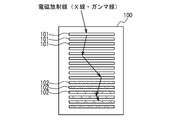
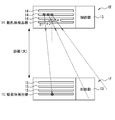
- FIG. 1 shows the principle of the Compton camera, in particular the particular principle of the direction of incidence of the electromagnetic radiation.
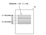
- the detection unit of the Compton camera typically includes a scatterer detector 101 and an absorber detector 102. In order to increase detection efficiency, each may be arranged in a plurality of layers.
- photons of electromagnetic radiation incident from a certain radiation source 103 are Compton scattered in the scatterer detector 101, and photons Compton scattered are absorbed by photoelectric absorption in the absorber detector 102.
- the scattering angle ⁇ of the electromagnetic radiation (in other words, the angle between the line connecting the radiation source 103 and the position X1 to the straight line passing the positions X1 and X2) is given by the following equation (1) Given.
- E 1 is energy obtained by recoil electrons by Compton scattering in the scatterer detector 101
- E 2 is energy of photons absorbed by the absorber detector 102.
- requirements for Compton cameras include, for example: (A) High energy resolution for identifying various nuclear gamma rays (for example, ⁇ E / E is about 3%) (B) High resolution (for example, an angular resolution of 10 degrees or less) of the gamma ray arrival direction for specifying the position and distance at which the radiation source accumulates.
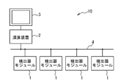
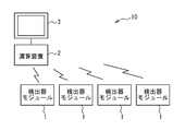
- the computing device is such that Compton scattering occurs in a scatterer detector of a first detector module among the plurality of detector modules, and photons scattered by the Compton scattering are detected among the plurality of detector modules.
- the event It is configured to reconstruct a Compton cone corresponding to and to generate a source distribution image based on the Compton cone.
- the computing device supplies synchronization data or a synchronization signal to each of the plurality of detector modules, and each of the plurality of detector modules generates measurement time data generated in synchronization with the synchronization data or the synchronization signal.
- Generate digital communication data to include
- the computing device Based on measurement time data, the computing device generates Compton scattering at the scatterer detector of the first detector module, and photons scattered by Compton scattering at the absorber detector of the second detector module Detect the occurrence of an event that causes absorbed photoelectric absorption. According to such a configuration, even if Compton scattering and photoelectric absorption occur in different detector modules, it can be reliably detected that they are related to the same photon.
- the digital processing unit 18 determines from the digital measurement data received from the ASICs 16 and 17 the position X1 at which Compton scattering has occurred, the energy E 1 obtained by recoil electrons by the Compton scattering, and the electromagnetic waves after scattering. radiation is absorbed by the absorber detector 15 position X2, and may be configured to perform operations to identify the energy E 2 of the electromagnetic radiation that has been absorbed into the absorbent body detector 15.
- the digital processing unit 18, a position X1, the energy E 1, the position X2, and the energy E 2 to generate a digital communication data including data describing, computing device by the communication interface 19 the generated digital communication data Send to 2
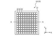
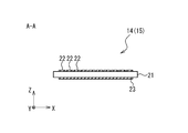
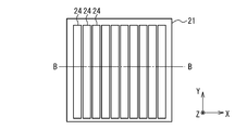
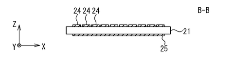
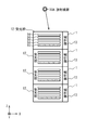
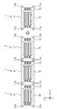
- each detector board 32 includes a substrate 36 on which the scatterer detector 14 and the ASIC 16 connected to the scatterer detector 14 are mounted.
- each scatterer detector 14 is divided into four regions, and four ASICs 16 are provided corresponding to the four regions. That is, each detector board 32 is provided with one scatterer detector 14 and four ASICs 16.
- Each ASIC 16 is connected to the corresponding area of the scatterer detector 14 through the wiring 37, and performs analog-digital conversion on the analog signal read out from the cell of the corresponding area to generate digital measurement data. .
- the ASIC 16 is further connected to the digital processing unit 18 via a wire 38.
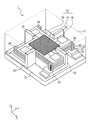
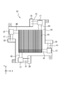
- the number of scatterer detectors 14 included in the light receiving unit 12 of each detector module 1 is four, and thus the number of detector boards 32 is also four.
- the plurality of detector modules 1 it is necessary for the plurality of detector modules 1 to operate in synchronization in time.
- a radiation measurement apparatus capable of responding to various requirements (that is, applicable to various applications) by operating the plurality of detector modules 1 synchronously in time. Ten have been realized.
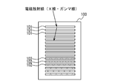
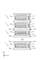
- FIG. 19A is a diagram showing an example of the arrangement of detector modules 1 (1E, 1F) for increasing the viewing angle.
- the detector module 1E provided with the scatterer detector 14 and the detector module 1F provided with the absorber detector 15 have a smaller distance.
- 1E and 1F are arranged.
- the electromagnetic radiation can be detected even when the scattering angle ⁇ is relatively large (for example, the scattering angles ⁇ 2 and ⁇ 3 in FIG. 19A), and as a result, the viewing angle becomes large.
- the angular resolution of the scattering angle ⁇ decreases.
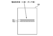
- FIG. 19B shows an example of the arrangement of detector modules 1 (1E, 1F) for increasing the angular resolution of the scattering angle ⁇ .
- the detector module 1E is arranged such that the distance between the detector module 1E provided with the scatterer detector 14 and the detector module 1F provided with the absorber detector 15 is increased.
- 1F is arranged.
- electromagnetic radiation can not be detected when the scattering angle ⁇ is relatively large (for example, the scattering angles ⁇ 2 and ⁇ 3 in FIG. 19A).
- the scattering angle ⁇ can be specified finely, the angular resolution of the scattering angle ⁇ can be improved.
- the time indicated in the measurement time data attached to the digital measurement data in which the occurrence of photoelectric absorption is detected is the same (or the predetermined time difference between the times indicated in the measurement time data is extremely short) In the case of smaller than time), it may be determined that the Compton scattering and the photoelectric absorption are events for the same photon.
Landscapes
- Physics & Mathematics (AREA)
- Spectroscopy & Molecular Physics (AREA)
- Health & Medical Sciences (AREA)
- Life Sciences & Earth Sciences (AREA)
- General Physics & Mathematics (AREA)
- High Energy & Nuclear Physics (AREA)
- Molecular Biology (AREA)
- Measurement Of Radiation (AREA)
- Toxicology (AREA)
Priority Applications (2)
| Application Number | Priority Date | Filing Date | Title |
|---|---|---|---|
| EP16830467.3A EP3282288B1 (en) | 2015-07-24 | 2016-07-22 | Radiation measuring apparatus and radiation measuring method |
| US15/575,144 US20180356540A1 (en) | 2015-07-24 | 2016-07-22 | Radiation measuring apparatus and radiation measuring method |
Applications Claiming Priority (2)
| Application Number | Priority Date | Filing Date | Title |
|---|---|---|---|
| JP2015147065A JP6485910B2 (ja) | 2015-07-24 | 2015-07-24 | 放射線測定装置及び放射線測定方法 |
| JP2015-147065 | 2015-07-24 |
Publications (1)
| Publication Number | Publication Date |
|---|---|
| WO2017018362A1 true WO2017018362A1 (ja) | 2017-02-02 |
Family
ID=57885134
Family Applications (1)
| Application Number | Title | Priority Date | Filing Date |
|---|---|---|---|
| PCT/JP2016/071641 Ceased WO2017018362A1 (ja) | 2015-07-24 | 2016-07-22 | 放射線測定装置及び放射線測定方法 |
Country Status (4)
| Country | Link |
|---|---|
| US (1) | US20180356540A1 (enExample) |
| EP (1) | EP3282288B1 (enExample) |
| JP (1) | JP6485910B2 (enExample) |
| WO (1) | WO2017018362A1 (enExample) |
Families Citing this family (7)
| Publication number | Priority date | Publication date | Assignee | Title |
|---|---|---|---|---|
| EP3818395B1 (en) * | 2018-08-07 | 2023-02-08 | Siemens Medical Solutions USA, Inc. | Compton camera with segmented detection modules |
| CN109375250B (zh) * | 2018-12-24 | 2024-05-14 | 同方威视技术股份有限公司 | 探测器系统和辐射成像装置 |
| CN109633733B (zh) * | 2019-01-25 | 2022-06-10 | 成都理工大学 | 采用粒子事件读出方式的数字化反康普顿能谱测量系统 |
| WO2021150964A1 (en) * | 2020-01-23 | 2021-07-29 | Rapiscan Systems, Inc. | Systems and methods for compton scatter and/or pulse pileup detection |
| CN113951914B (zh) * | 2021-10-20 | 2023-06-27 | 上海联影医疗科技股份有限公司 | 一种pet设备及其时钟同步方法和装置 |
| CN114464060B (zh) * | 2022-03-03 | 2023-06-16 | 中国石油大学(华东) | 一种射线吸收虚拟仿真实验系统及方法 |
| CN119805007B (zh) * | 2024-12-31 | 2025-09-30 | 中国人民解放军海军工程大学 | 一种便携式vlf辐射效率测量平台及方法 |
Citations (3)
| Publication number | Priority date | Publication date | Assignee | Title |
|---|---|---|---|---|
| JP2005208057A (ja) * | 2003-12-26 | 2005-08-04 | Institute Of Physical & Chemical Research | ガンマ線検出器及びガンマ線撮像装置 |
| WO2012077468A1 (ja) * | 2010-12-09 | 2012-06-14 | 独立行政法人理化学研究所 | ガンマ線を利用する画像化装置、画像信号処理装置およびガンマ線測定データの画像処理方法 |
| JP2015075424A (ja) * | 2013-10-10 | 2015-04-20 | 学校法人早稲田大学 | コンプトンカメラ |
Family Cites Families (5)
| Publication number | Priority date | Publication date | Assignee | Title |
|---|---|---|---|---|
| US6346706B1 (en) * | 1999-06-24 | 2002-02-12 | The Regents Of The University Of Michigan | High resolution photon detector |
| US7291841B2 (en) * | 2003-06-16 | 2007-11-06 | Robert Sigurd Nelson | Device and system for enhanced SPECT, PET, and Compton scatter imaging in nuclear medicine |
| US8063379B2 (en) * | 2006-06-21 | 2011-11-22 | Avraham Suhami | Radiation cameras |
| JP2010032451A (ja) * | 2008-07-31 | 2010-02-12 | Hitachi Ltd | 粒子線照射システム |
| JP5467839B2 (ja) * | 2009-10-13 | 2014-04-09 | 日立アロカメディカル株式会社 | 放射線測定装置 |
-
2015
- 2015-07-24 JP JP2015147065A patent/JP6485910B2/ja active Active
-
2016
- 2016-07-22 US US15/575,144 patent/US20180356540A1/en not_active Abandoned
- 2016-07-22 EP EP16830467.3A patent/EP3282288B1/en active Active
- 2016-07-22 WO PCT/JP2016/071641 patent/WO2017018362A1/ja not_active Ceased
Patent Citations (3)
| Publication number | Priority date | Publication date | Assignee | Title |
|---|---|---|---|---|
| JP2005208057A (ja) * | 2003-12-26 | 2005-08-04 | Institute Of Physical & Chemical Research | ガンマ線検出器及びガンマ線撮像装置 |
| WO2012077468A1 (ja) * | 2010-12-09 | 2012-06-14 | 独立行政法人理化学研究所 | ガンマ線を利用する画像化装置、画像信号処理装置およびガンマ線測定データの画像処理方法 |
| JP2015075424A (ja) * | 2013-10-10 | 2015-04-20 | 学校法人早稲田大学 | コンプトンカメラ |
Also Published As
| Publication number | Publication date |
|---|---|
| US20180356540A1 (en) | 2018-12-13 |
| JP6485910B2 (ja) | 2019-03-20 |
| EP3282288A4 (en) | 2018-05-16 |
| EP3282288A1 (en) | 2018-02-14 |
| JP2017026526A (ja) | 2017-02-02 |
| EP3282288B1 (en) | 2022-08-17 |
Similar Documents
| Publication | Publication Date | Title |
|---|---|---|
| WO2017018362A1 (ja) | 放射線測定装置及び放射線測定方法 | |
| EP2376940B1 (en) | Autonomous detector module as a building block for scalable pet and spect systems | |
| JP6499172B2 (ja) | 結晶またはディテクタユニットに間隔を有するpetシステム | |
| JP6551003B2 (ja) | 放射線測定装置及び放射線測定方法 | |
| JP4594624B2 (ja) | 放射線検出装置および核医学診断装置 | |
| RU2647206C1 (ru) | Сенсорное устройство и система визуализации для обнаружения сигналов излучения | |
| WO2008018534A1 (fr) | détecteur de rayons gamma | |
| US7645998B2 (en) | Detector module, detector and computed tomography unit | |
| WO2017123777A1 (en) | Fabrication and operation of multi-function flexible radiation detection systems | |
| US20140348290A1 (en) | Apparatus and Method for Low Capacitance Packaging for Direct Conversion X-Ray or Gamma Ray Detector | |
| JP2021534376A (ja) | 医療用画像用略2πコンプトンカメラ | |
| US10175368B2 (en) | Detector for Compton camera and Compton camera | |
| JP2016223997A (ja) | 放射線カメラ | |
| JP3976259B2 (ja) | ポジトロンエミッショントモグラフィ装置 | |
| Cerbone et al. | Monte Carlo and experimental evaluation of a Timepix4 compact gamma camera for coded aperture nuclear medicine imaging with depth resolution | |
| JP4934826B2 (ja) | 放射線画像検出モジュールおよび放射線画像検出装置 | |
| KR101994539B1 (ko) | 콤프턴 단층 촬영 시스템 및 방법 | |
| US20130119258A1 (en) | Method and apparatus for the detection of x-ray quants | |
| JP4464998B2 (ja) | 半導体検出器モジュール、および該半導体検出器モジュールを用いた放射線検出装置または核医学診断装置 | |
| JP2000019254A (ja) | 放射線診断装置 | |
| KR20210045766A (ko) | 컴프턴 영상 장치 및 이를 포함하는 단일 광자 및 양전자 단층 촬영 시스템 | |
| JPH1172566A (ja) | ガンマカメラシステム | |
| JP7496181B1 (ja) | 測定装置および測定方法 | |
| JP2017096724A (ja) | 放射線検出装置 | |
| JP2015102504A (ja) | ガンマカメラ |
Legal Events
| Date | Code | Title | Description |
|---|---|---|---|
| 121 | Ep: the epo has been informed by wipo that ep was designated in this application |
Ref document number: 16830467 Country of ref document: EP Kind code of ref document: A1 |
|
| NENP | Non-entry into the national phase |
Ref country code: DE |