WO2017018230A1 - 画像処理装置、方法、及びプログラム - Google Patents
画像処理装置、方法、及びプログラム Download PDFInfo
- Publication number
- WO2017018230A1 WO2017018230A1 PCT/JP2016/070851 JP2016070851W WO2017018230A1 WO 2017018230 A1 WO2017018230 A1 WO 2017018230A1 JP 2016070851 W JP2016070851 W JP 2016070851W WO 2017018230 A1 WO2017018230 A1 WO 2017018230A1
- Authority
- WO
- WIPO (PCT)
- Prior art keywords
- dimensional
- range
- attention
- image processing
- image
- Prior art date
- Legal status (The legal status is an assumption and is not a legal conclusion. Google has not performed a legal analysis and makes no representation as to the accuracy of the status listed.)
- Ceased
Links
Images


Classifications
-
- A—HUMAN NECESSITIES
- A61—MEDICAL OR VETERINARY SCIENCE; HYGIENE
- A61B—DIAGNOSIS; SURGERY; IDENTIFICATION
- A61B6/00—Apparatus or devices for radiation diagnosis; Apparatus or devices for radiation diagnosis combined with radiation therapy equipment
- A61B6/02—Arrangements for diagnosis sequentially in different planes; Stereoscopic radiation diagnosis
- A61B6/03—Computed tomography [CT]
Definitions
- the present invention relates to an image processing apparatus, and more particularly to an image processing technique for reducing the burden on an image reader.
- a photographed three-dimensional medical image is obtained as a continuous two-dimensional cross-sectional image. It is common to perform reconstruction by reconstructing and observing the two-dimensional cross-sectional image.
- the three-dimensional resolution of generated three-dimensional medical images has also improved, and the data size tends to increase.
- the two-dimensional cross-sectional image generation interval described above can be made finer, and more detailed observation of the lesion appearing on the medical image has become possible.
- the number of cross sections has also increased.
- the CT apparatus it has become possible to capture a high-quality three-dimensional medical image with a low dose, and the number of CT image capturing opportunities tends to increase.
- Patent Document 1 proposes a method of reducing the number of cross sections other than the periphery of the position of the findings image based on the doctor's input findings.
- the range defined as the surrounding area of the findings is the tertiary of individual suspected lesions. No consideration is given to individual differences such as original size. Therefore, when the size specified in advance as the finding peripheral region is different from the size of the lesion, the suspected lesion region, which is a suspected lesion region, is not always included in the finding peripheral region. As a result, there are problems such as a problem that the amount of the two-dimensional image to be interpreted cannot be reduced sufficiently and an image required by the interpreter cannot be displayed without a shortage.
- An object of the present invention is to solve these problems and provide an image processing apparatus, method, and program capable of reducing the burden on an image interpreter regardless of individual differences in suspected lesion areas.
- an image processing apparatus comprising a stack of a plurality of two-dimensional cross-sectional images orthogonal to the first direction, from a point of interest for a medical image for calculation of a subject, A three-dimensional interpretation medical image is generated by specifying different resolutions for the attention range specifying unit for specifying the attention range in the first direction and the attention range in the first direction and the non-attention range in the first direction.
- a medical image generation unit for interpretation, and the attention range specifying unit calculates a two-dimensional attention range on the two-dimensional cross-sectional image where the attention point exists, and based on the two-dimensional attention range, between the two-dimensional sectional images in the first direction
- An image processing apparatus that specifies a range of interest in the first direction by calculating a first direction similarity that indicates the degree of similarity is provided.
- an image processing method in an image processing apparatus wherein the image processing apparatus comprises a plurality of two-dimensional cross-sectional images orthogonal to a first direction.
- the attention range in the first direction is specified by calculating the similarity, and different resolutions are specified for the attention range in the first direction and the non-attention range in the first direction, and a three-dimensional medical image for interpretation is obtained.
- An image processing method to be generated is provided.
- an image processing program in an image processing apparatus comprising a stack of a plurality of two-dimensional cross-sectional images orthogonal to the first direction.
- the attention range in the first direction is specified by calculating the similarity, and different resolutions are specified for the attention range in the first direction and the non-attention range in the first direction, and a three-dimensional medical image for interpretation is obtained.
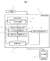
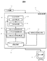
- FIG. 1 is a system configuration diagram including an example of an image processing apparatus according to Embodiment 1.
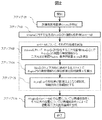
- FIG. FIG. 6 is a flowchart illustrating an example of a three-dimensional medical image generation process for interpretation performed by the image processing apparatus according to the first embodiment.
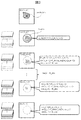
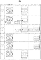
- 6 is a schematic diagram illustrating a flow of calculation processing for a three-dimensional medical image for calculation according to Embodiment 1.
- FIG. 10 is a flowchart illustrating an example of processing for specifying a body axis direction attention range from a two-dimensional medical image parallel to the body axis direction according to a third embodiment.
- FIG. 10 is a system configuration diagram illustrating a configuration of an image processing apparatus that automatically identifies a point of interest according to a fourth embodiment.
- FIG. 10 is a flowchart illustrating an example of processing for sequentially executing identification of a point of interest and generation of a medical image for interpretation according to a fifth embodiment.
- FIG. 10 is a diagram illustrating a two-dimensional cross-sectional image displayed on a display device in a process of sequentially executing a point-of-interest specification and an interpretation medical image generation according to a fifth embodiment.
- the attention point and the attention range are determined based on medical knowledge of an interpreter such as an interpreting doctor who interprets a medical image, medical evidence for the disease diagnosis, and the like. Points and areas with high suspicion of lesions.
- the point of interest or the range of interest is designated or specified automatically or manually.
- the first direction is the body axis direction
- a body axis (axial) cross-sectional image orthogonal to the body axis direction is used as the attention two-dimensional image, from the subject's attention point to the body axis
- the cross-sectional image orthogonal to the first direction as the attention two-dimensional image is not limited to the axial cross-sectional image, but is a sagittal cross-sectional image, a coronal cross-sectional image, or an oblique cross-sectional image. Images can be used.
- the first direction of interest specified from the subject's attention point is applied to the attention range of the first direction in the sagittal direction, the coronal direction, and the oblique direction. It will be. Further, in the following description of the embodiments, terms such as body axis direction similarity, body axis direction similarity calculation formula, body axis direction similarity reference range, etc. are used, which are respectively the first direction similarity and the first direction. It is shown as an example of the similarity calculation formula, the first direction similarity reference range, etc., and is not limited to the body axis direction.
- the attention range in the body axis direction which is the first direction from the attention point automatically or manually specified for the medical image is specified, and the attention range and other than the attention range (hereinafter referred to as the non-attention range)
- the non-attention range This is an embodiment of an image processing apparatus for reconstructing a three-dimensional medical image for interpretation under different reconstruction conditions.
- the present embodiment is an image processing apparatus 11, in which attention is paid in the body axis direction from a point of interest with respect to the medical image for calculation of the subject, which is a stack of a plurality of two-dimensional cross-sectional images orthogonal to the body axis direction.
- a body axis direction attention range specifying unit 21 that specifies a range, and a reading that generates a three-dimensional medical image by specifying different resolutions for the attention range in the body axis direction and the non-attention range in the body axis direction
- a body axis direction attention range specifying unit 21 calculates a two-dimensional attention range on a two-dimensional cross-sectional image where the point of interest exists, and based on the two-dimensional attention range, It is an Example of the image processing apparatus of the structure which identifies the attention range of a body axis direction by calculating the 1st direction similarity which shows the similarity between two-dimensional cross-sectional images, and a program.
- a reconstructed three-dimensional medical image obtained by a CT medical image photographing apparatus will be described, but the present technology can also be applied to data obtained by other medical image photographing apparatuses.
- the data is obtained by an MRI imaging apparatus or the like, it is possible to obtain a three-dimensional image that can be expressed as a stack of a plurality of two-dimensional cross-sectional images, and is applicable if lesion characteristics appear in the pixel distribution. be able to.
- the point of interest specified and the range of interest to be specified in this embodiment are highly likely to be a lesion determined based on medical knowledge such as an interpreting doctor or medical evidence (evidence) for the disease diagnosis. Points and areas with high suspicion of lesions.
- the target lesion is highly likely to be judged from the difference in luminance and the distribution from the surrounding area, that is, the region with low suspicion of the lesion, when it appears on the medical image.
- the CT value appears on the CT image as a region including many pixels higher than the surrounding air region.
- the attention range mainly refers to a region having a high suspicion of a lesion
- the attention point refers to one point in a region having a high suspicion of a lesion.
- the point of interest may be the center of gravity of the range of interest or any point around it.
- FIG. 1 is a system configuration diagram including an example of an image processing apparatus according to the present embodiment.
- the present system includes an image processing device 11, an input device 10 that receives an operator's input and transmits it to the image processing device 11, and a display that displays a medical image obtained from the image processing device 11.
- the apparatus 12 is comprised.
- the image processing apparatus 11 includes a plurality of functional blocks, that is, a calculation medical image having a single resolution in the body axis direction exemplified as the first direction, and reconstruction conditions that are different between the attention range and the non-attention range,
- an image storage unit 22 that stores a three-dimensional interpretation medical image generated with a lower resolution than the attention range, and an attention point that specifies a point of interest for the calculation medical image obtained from the image storage unit 22
- Body axis direction attention range identification for calculating the body axis direction attention range of the medical image for calculation from the point identification unit 20, the attention point obtained from the attention point identification unit 20 and the medical image for calculation obtained from the image storage unit 22.
- an interpretation medical image generation unit 23 that generates an interpretation medical image using the body axis direction attention range identified by the body axis direction attention range identification unit 21.
- the attention point specifying unit 20 includes an attention point storage unit 40 that stores attention points for a plurality of calculated medical images stored in the image storage unit 22 in a form corresponding to each of the calculation medical images.
- the attention point storage unit 40 may be configured by the same storage unit as the image storage unit 22.
- the body axis direction attention range specifying unit 21 calculates a two-dimensional attention range for a two-dimensional cross-sectional image orthogonal to the body axis in the calculation medical image from the attention points for the calculation medical image obtained from the attention point specification unit 20.
- the body axis direction that is the first direction for each of a plurality of two-dimensional cross-sectional images of the medical image for calculation
- a body axis direction attention range calculation unit 31 for calculating a body axis direction similarity between two adjacent two-dimensional cross-sectional images and calculating a body axis direction attention range with respect to the medical image for calculation, and a two-dimensional feature not shown in the figure.
- the reference feature amount storage unit can also be configured by the same storage unit as the image storage unit 22.
- the two-dimensional feature value calculation formula is a predetermined formula for calculating the two-dimensional feature value from at least the luminance difference between adjacent pixels for each pixel on the two-dimensional cross-sectional image of the three-dimensional medical image.
- the two-dimensional feature quantity reference range means a predetermined range that can be taken by a region of interest serving as a reference for the two-dimensional feature quantity.
- the body axis direction similarity calculation formula calculates an in-plane feature value obtained from an average value of a plurality of pixels in at least a specific two-dimensional region in each of a plurality of two-dimensional cross-sectional images, and calculates from the target two-dimensional cross section.
- the image processing apparatus 11 described above can be realized by a computer including a central processing unit (CPU) that executes an image processing program and a storage unit that stores programs and data, such as an ordinary personal computer.
- the input device 10 and the display device 12 can also use an input unit such as a keyboard and a mouse of the above computer and a display.
- the image processing program according to the present embodiment preferably uses the CPU to specify the range of interest in the body axis direction of the subject from the point of interest with respect to the subject's computational medical image.
- the body axis direction By calculating the two-dimensional attention range from the luminance value distribution of the pixels around the attention point on the attention two-dimensional image where the attention point exists, and calculating the body axis direction similarity from the two-dimensional attention range, the body axis direction
- the first reconstruction condition that calculates the attention range and specifies the body axis direction resolution for the body axis direction attention range, and the body reconstruction direction resolution that is lower than the first reconstruction condition for the non-attention range
- the image processing apparatus 11 specifies a calculation medical image Volume to be processed from a plurality of calculation medical images stored in the image storage unit 22 by an input from the system or an instruction from a user (step 101). ).
- slice [s] is a two-dimensional image, that is, pixels are arranged in a grid.
- the two-dimensional cross-sectional image Slice [s] here is assumed to be arranged in order from the top to the bottom of the subject's body axis, in other words, from the head to the foot. That is, Slice [1] is a cross section on the most head side, and Slice [ns] is a cross section on the most foot side.
- s 1 to ns is referred to as a section number.
- M 0, that is, when there is no point of interest for Volume, the subsequent processing is not performed, and a three-dimensional medical image is generated according to a predetermined reconstruction condition.
- the two-dimensional attention range calculation unit 30 specifies the slice [s_m] where the Point [m] exists in the Volume, and calculates the two-dimensional attention range Region [m] from the luminance information around the Point [m]. (Step 103). That is, the two-dimensional attention range calculation unit 30 calculates a two-dimensional feature amount calculated by a two-dimensional feature amount calculation formula read from the reference feature amount storage unit in the attention two-dimensional cross-sectional image where the attention point exists, and the reference feature. The two-dimensional attention range is calculated with reference to the two-dimensional feature amount reference range read from the quantity storage unit.
- the reference feature quantity storage unit calculates a two-dimensional feature quantity from each pixel on the two-dimensional cross-sectional image of the three-dimensional medical image from at least the luminance difference between adjacent pixels.
- a two-dimensional feature amount reference range that can be taken by a region of interest serving as a reference for the two-dimensional feature amount is stored in advance. An example of the calculation method of Region [m] will be described later.
- the body axis direction attention range calculation unit 31 uses the reference feature amount ⁇ _org [m] on Slice [s_m] and the feature amount ⁇ [[ s] is calculated (step 104).
- ⁇ _org [m] ⁇ [s_m]
- ⁇ [s] is calculated by the same method as ⁇ _org [m].
- the body axis direction attention range calculation unit 31 is a two-dimensional cross-sectional image in which the body axis direction similarity sim [s] of ⁇ [s] and ⁇ _org [m] is equal to or greater than the threshold th_sim, and from Slice [s_m].
- the continuous range is set as a body axis direction attention range ARegion [m] with respect to Point [m], and is output to the medical image generation unit for interpretation X (step 105).
- the body axis direction attention range calculating unit 31 of the body axis direction attention range specifying unit 21 calculates the body axis direction similarity calculated by the body axis direction similarity calculation formula read from the reference feature amount storage unit, and the reference The body axis direction attention range is calculated with reference to the body axis direction similarity reference range read from the feature amount storage unit.
- the reference feature quantity storage unit (not shown) stores the similarity between the in-plane feature quantity obtained from the section of interest and the in-plane feature quantity obtained from a section other than the section of interest.
- the body axis direction similarity calculation formula calculated as the axis direction similarity and the body axis direction similarity reference range that can be taken by the body axis direction similarity with respect to the reference region of interest are stored in advance. A specific method for realizing Step 105 will be described later.
- reconstruction condition 2 that specifies the body axis direction resolution for the body axis direction attention range for all attention points, and other positions.
- preRegion [m] used in the previous stage of calculating Region [m] is used.
- preRegion [m] is a two-dimensional region including Point [m] and is represented by a set of pixels that satisfy a predetermined determination condition.
- the determination condition includes, for example, whether or not the luminance difference from Point [m] is equal to or less than a threshold value.
- the two-dimensional feature value is a luminance difference from Point [m]
- the two-dimensional feature value reference range is a value range defined by a lower limit threshold and an upper limit threshold for the luminance difference.
- Other determination conditions include two-dimensionally continuing from Point [m], and the luminance difference from adjacent pixels is equal to or less than a threshold value, or both are satisfied.
- a conventionally known two-dimensional region extraction method such as a Graphcuts method or a watershed method can also be used.
- Region [m] is calculated as a two-dimensional region including preRegion [m].
- the shape of Region [m] may be expressed as a geometric shape such as a rectangle or a circle, or may be expressed as a free shape expressed as a point set.
- a geometric shape a minimum shape including preReion or a multiple of the minimum shape is used, and in the case of a free shape, the convex hull of preRegion [m], that is, the minimum convex shape including preRegion [m] It is possible to use the shape.
- FIG. 3 described later shows a flow of calculation processing for a three-dimensional medical image when Region [m] is the smallest circle including preRegin [m], and preRegin [m] in FIG. The crosses in the middle schematically show the points of interest.
- ⁇ _org [m] is calculated using the luminance of the pixels in the two-dimensional region of interest Region [m] on Slice [s_m] and the luminance of the surrounding pixels. For example, a histogram of pixel values in Region [m] is calculated, and the median and variance are ⁇ _org [m].
- ⁇ _org [m] can also include an average value of luminance differences between adjacent pixels of the pixel values in Region [m], and can be expressed as a vector composed of a plurality of values.
- ⁇ [s] calculated by the body axis direction attention range calculation unit 31 in step 104 is calculated from pixels in the two-dimensional attention range Region [m] on Slice [s] by the same calculation formula as ⁇ _org [m]. Shall be.
- a specific method for the case where the body axis direction attention range calculation unit 31 calculates the body axis direction attention range in step 105 will be described.
- the determination of the body axis direction similarity is also performed on the slice [s_m], which is a continuous two-dimensional cross-sectional image in the upward direction, that is, slice [s (s ⁇ s_m)], and the determination is completed
- the cross-sectional number of the two-dimensional cross-sectional image immediately below the cross-sectional image is set as the upper end S_cs of the target slice group.
- Step 105 is ended with the above-described ARegion [m] in the range from the upper end to the lower end of the slice group of interest thus obtained, that is, the range from S_cs to S_ce.
- ARegion [m] is represented by the cross-sectional position of the medical image for calculation.
- the body axis direction attention range specifying unit 21 performs the real space from the coordinate system of the temporary medical image after step 105. Also converts values to the coordinate system.
- the interpretation medical image generation unit 23 may perform conversion to a range in the real space coordinate system before step 106.
- FIG. 3 schematically shows the feature values calculated for each cross section.
- ⁇ _org [m] and ⁇ [s] are assumed to be feature quantity vectors (f1_s, f2_s) composed of f1_s and f2_s.
- f1_s and f2_s are numerical values calculated from the two-dimensional attention range Region [s] on Slice [s].
- ⁇ [s] is a vector composed of the median and variance of the pixel value histogram in Region [s]
- f1_s is the median value of the luminance histogram in Region [s]
- f2_s is Region. This is the variance of the luminance histogram in [s].
- a feature vector composed of two variables is taken as an example, but the number of variables may not be three.
- the body axis direction similarity sim [s] is a two-dimensional function f_sim ( ⁇ _org [m], ⁇ [s]) having ⁇ _org [m] and ⁇ [s] as input variables.
- the quadratic function f_sim ( ⁇ _org [m], ⁇ [s]) is, for example, the Euclidean distance of ⁇ _org [m] and ⁇ [s] on the feature space, that is, ⁇ ⁇ ( ⁇ _org [m] ⁇ [s]). ⁇ 2 ⁇ .
- examples of the body axis direction similarity reference range include a range of values represented by an upper limit threshold and a lower limit threshold for the body axis direction similarity.
- the left column of FIG. 3 schematically shows a three-dimensional image that is a stack of two-dimensional cross-sectional images
- the middle column schematically shows the image of the two-dimensional cross-sectional image.
- the target slice group is indicated by a solid line
- the other two-dimensional cross-sectional images are indicated by broken lines
- the two-dimensional cross-sectional images are filled with diagonal lines.
- a region having a high CT value is represented by diagonal lines.
- body axis direction similarity sim [s] ⁇ th_sim, and s closest to s_m is s_c (where s_c> s_m).
- the interpretation medical image generation unit 23 reconstructs an interpretation medical image from the raw data detected by the three-dimensional medical image photographing apparatus.
- the raw data here is, for example, the first data obtained by a CT imaging apparatus which is a three-dimensional medical imaging apparatus, and the X detector at each projection position after X-ray irradiation is performed in the CT imaging apparatus. This data indicates output and is stored in the image storage unit 22.
- Image data generally called 3D CT images, is reconstructed from the raw data, and the X-ray absorption rate of the imaging range is expressed in a form that reflects the pixels arranged in a grid in the 3D coordinate system.
- the reconstruction conditions 1 and 2 indicate conditions specified in the reconstruction process for converting the raw data into a three-dimensional medical image that can be interpreted. The same applies to a three-dimensional medical image photographing apparatus other than the CT photographing apparatus.
- the reconstruction conditions here are mainly the reconstruction interval, which is the interval for generating the two-dimensional cross-sectional image, the cross-sectional thickness indicating the thickness in the body axis direction to be reflected in one two-dimensional cross-sectional image, The type and strength of a reconstruction filter for realizing smoothing, noise reduction, and the like are shown.
- the reconstruction interval and the cross-sectional thickness are dis1, thi1 in the reconstruction condition 1, and dis2, thi2 in the reconstruction condition 2.
- reconstruction condition 1 for designating the body axis direction resolution for the body axis direction attention range, and a resolution in the body axis direction lower than reconstruction condition 1 for the non-attention range other than the attention range are designated.
- reconstruction condition 2 to be generated a three-dimensional medical image for interpretation is generated.
- the cross-sectional thickness ⁇ reconstruction interval in order not to generate an unimaged region.
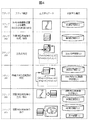
- FIG. 4 is a flowchart showing a step in the first row, a step summary in the second row, data output in the third row, and a configuration used in the fourth row in the fourth row.
- This flow includes steps 201 to 206.
- the image processing apparatus according to the present exemplary embodiment realizes steps 203 to 206.
- the medical image photographing apparatus photographs a patient according to a photographing instruction from a doctor such as a photographing range and photographing conditions, and stores a temporary medical image in the image storage unit 22 of the image processing apparatus 11 (step 201).
- the image processing apparatus 11 generates a calculation medical image using the temporary medical image and stores it in the image storage unit 22 (step 202).
- the reconstruction conditions when generating the calculation medical image from the temporary medical image are predetermined according to the imaging range and imaging conditions, or according to the instructions of the doctor before the imaging, and can be used as one 3D medical image.
- One reconstruction condition is used.
- the attention point specifying unit 20 specifies an attention point for the calculation medical image from the attention point storage unit 40 (Step 203), and the body axis direction attention range specifying unit 21 calculates the calculation medical image from the calculation medical image and the attention point.
- a body axis direction attention range for the image is specified (step 204).
- the interpretation medical image generation unit 23 generates a three-dimensional interpretation medical image from the temporary medical image (raw data) (step 205).
- the display device 12 displays the two-dimensional cross-sectional images of the medical image for interpretation stored in the image storage unit 22 one by one on the display screen (step 206).
- the processing in steps 204 and 205 is the same as the processing described as steps 103 to 106.
- the computational medical image is a computational three-dimensional medical image that can be expressed by stacking a plurality of two-dimensional cross-sectional images orthogonal to the body axis direction.
- the attention two-dimensional image is one of the two-dimensional cross-sectional images. It is.
- This three-dimensional medical image for calculation is reconstructed in advance according to a reconstruction condition that designates a body axis direction resolution equal to or higher than the body axis direction resolution of the first reconstruction condition.
- the medical image generation unit generates an interpretation medical image by thinning out the three-dimensional calculation medical image reconstructed in advance as described above.
- the reconstruction interval of the calculation three-dimensional medical image is set to dis_org, and the cross-sectional thickness is set to thi_org. At this time, dis1 ⁇ dis_org is satisfied.
- dis1 dis_org
- the two-dimensional cross-sectional image constituting the medical image for calculation can be used as it is as the two-dimensional cross-sectional image constituting the medical image for interpretation for the attention range in the body axis direction.
- a two-dimensional cross-sectional image extracted every other dis2 from the medical image for calculation is used as the two-dimensional medical image constituting the medical image for interpretation, or within the range of dis2.
- Interpretation of a medical image for interpretation as a single two-dimensional image obtained by averaging a plurality of two-dimensional cross-sectional images in the direction of the body axis or using an image processing means such as MIP (Maximum Intensity Projection). Is a two-dimensional cross-sectional image.
- a method for generating a medical image for interpretation from raw data has been described.
- raw data is often deleted after a certain period of time depending on a facility where an image processing apparatus is installed. Therefore, there is a possibility that raw data cannot be obtained, for example, when the present system is used at a timing not immediately after photographing.
- This can be done, for example, by taking a medical image generated by this technology when the facility performing the radiography, such as remote interpretation, and the facility performing the radiography are different facilities, or by observing the progress of the lesion.
- a medical image taken after the date and time is compared with a medical image taken of a medical image generated by the present technology.
- the effect of the present embodiment is that a medical image for interpretation can be generated without using raw data even in these cases.
- the body axis direction attention range specifying unit of the image processing apparatus 11 illustrated in FIG. 1 specifies the body axis direction attention range from a two-dimensional medical image parallel to the body axis direction, such as an XR image or a scanogram. It is an Example of a structure. That is, here, the medical image for calculation is a single two-dimensional image.
- the two-dimensional attention range calculation unit 30 of the body axis direction attention range specifying unit 21 calculates the two-dimensional attention range Region from the luminance information around Point [m] in the Image ( Step 303).
- the Region here can be obtained by the same calculation method as the preRegion in the first embodiment.
- the body axis direction attention range calculation unit 31 calculates the body axis direction attention range ARegion [m] based on the region information (step 304).
- ARegion [m] can be calculated, for example, as a range from the minimum value to the maximum value among the coordinate values of the region pixels in the body axis direction.
- the image processing apparatus of the present embodiment it is possible to specify the attention range in the body axis direction without generating a three-dimensional image, so that it is possible to shorten the time from imaging to completion of a medical image for interpretation.
- the attention point specifying unit of the image processing apparatus shown in FIG. 1 is configured to automatically determine the attention point. That is, the attention point specifying unit 20 in FIG. 6 includes an attention point calculation unit 41 and an attention point storage unit 40, and the attention point storage unit 40 obtains a cubic from the pixel distribution around each pixel of the three-dimensional medical image for calculation.
- a three-dimensional feature value calculation formula for calculating the original feature value and a three-dimensional feature value reference range that is a range of values that can be taken by the three-dimensional feature value are stored in advance, and the attention point calculating unit 41 stores the three-dimensional feature value.
- the attention point identification unit 20 of this embodiment includes an attention point calculation unit 41 in addition to the attention point storage unit 40.
- the attention point calculation unit 41 automatically specifies the attention point using the calculation three-dimensional medical image.
- the attention point calculation unit 41 for example, a histogram median value calculated from a luminance distribution in a sphere centered on each pixel of a calculation three-dimensional medical image, a numerical value such as a variance, or between adjacent pixels
- a luminance difference or the like can be calculated as a three-dimensional feature value
- a pixel that falls within a three-dimensional feature value reference range that is a predetermined threshold range can be stored in the attention point storage unit 40 as an attention point.
- the three-dimensional feature amount reference range stored in the point-of-interest storage unit 40 is a group of test medical images photographed by photographing apparatuses having the same photographing conditions and photographing device specifications, with a lesion suspected portion having the same disease type as the attention region. And the result of interpretation of the result.
- the body axis direction attention range specifying unit 21 needs to specify the body axis direction attention range by the method described in the first embodiment.
- the attention point specifying unit 20 can calculate the entire suspicious lesion region as a three-dimensional region as the attention region
- the attention point storage unit 40 stores a plurality of attention regions that are one lesion suspicion region.
- the three-dimensional region represented by the point of interest is stored, and the body axis direction attention range specifying unit 20 has a height parallel to the body axis direction and the height of a cylinder or polygonal column that encompasses the range of interest. Can be set as the attention range in the body axis direction.
- the calculation of the attention point by the attention point calculation unit 41 and the storage in the attention point storage unit 40 may be executed, for example, as a preceding stage of Step 102, Step 203, and Step 302. , 203, and 302, it is possible to simply read the attention point from the attention point storage unit 40.
- the three-dimensional feature amount reference range stored in the attention point storage unit is a test medical image imaged by an imaging device having the same imaging conditions and imaging equipment specifications, with a suspected lesion area having the same disease type as an attention area. It is determined in advance from the group and the interpretation results.
- CAD Computer Aided Detection
- CAD refers to a system and a method for automatically calculating and presenting a point of interest as a suspected lesion from a medical image by a computer and information processing technology based on the computer.
- the position is designated with respect to the three-dimensional or two-dimensional medical image.
- the reconstruction interval of the reconstruction condition is a value larger than at least dis1, For example, the effect of the present technology can be obtained by using dis2.
- a rough reconstruction interval that is, with a small number of cross-sections, and details of a point designated as a point of interest can be confirmed with a small reconstruction interval.
- an interpreting doctor who is an operator specifies a point of interest while interpreting using a cross-sectional image with a coarse body-axis direction resolution
- the body-axis resolution of the specified cross-sectional image and the surrounding cross-sectional images Can be made finer.
- Step 103 to Step 106 described in the first embodiment are real-time processing, it is possible to observe details in the peripheral area of the target point without interpreting the entire three-dimensional medical image twice.
- FIG. 7 A processing flow when the steps 103 to 106 shown in FIG. 2 are real-time processing will be described with reference to FIGS. 7 and 8.
- FIG. 7 A processing flow when the steps 103 to 106 shown in FIG. 2 are real-time processing will be described with reference to FIGS. 7 and 8.
- FIG. 7 A processing flow when the steps 103 to 106 shown in FIG. 2 are real-time processing will be described with reference to FIGS. 7 and 8.
- the medical image to be displayed for specifying the attention point is Volume A, and it is composed of a stack of snA two-dimensional cross-sectional images Slice A [sA] orthogonal to the body axis reconstructed at a constant reconstruction interval.
- sA is a slice number of Slice A, and is a variable that takes a value of 1 to snA.
- the medical image for interpretation is Volume B, and it is composed of a stack of snB two-dimensional cross-sectional images Slice B [sB] orthogonal to the body axis.
- sB is a slice number of SliceB, and is a variable having a value of 1 to snB.
- snB> snA the values of sA and sB are different even in a two-dimensional cross-sectional image existing at the same position in the body axis direction of the real coordinate system.
- FIG. 7 is a flowchart showing an example of processing for sequentially executing the point-of-interest specification and the interpretation medical image generation, and includes steps 401 to 408.
- FIG. 8 is a diagram illustrating the position of the two-dimensional cross-sectional image displayed on the display device at each step in steps 402 to 408 here.
- the two-dimensional cross-sectional image displayed in this step is indicated by a solid line, and the other two-dimensional cross-sectional images are indicated by a broken line.
- the image processing apparatus 11 specifies Volume A in the same manner as Step 101 in the first embodiment (Step 401).
- the subsequent steps 402 to 409 are executed sequentially with a time-series context for Slice A [sA] of 1 to snA.
- Slice A [sA] is displayed on the display device 12 (step 402).
- step 403 the presence / absence of the point of interest Point for Slice A [sA] is determined based on an input from the input device 10, and this determination is performed as follows, for example.
- a mouse When a mouse is used as the input device 10, when a right click is performed on the display screen, an operation of determining that the point of interest exists and setting the position of the click point as the point of interest and displaying the next two-dimensional cross-sectional image; For example, when a scroll operation or a down arrow button is pressed, it is determined that no point of interest exists in Slice A [sA]. Even if the input device 10 is a device other than a mouse, such as a trackball, a pen, or a touch panel, the determination can be made as long as the image turning operation and the point designation operation can be distinguished.
- step 403 When it is determined in step 403 that there is a point of interest in Slice A [sA], the process proceeds to step 404.
- the body axis direction attention range specifying unit 21 calculates the body axis direction attention range with respect to Point, as in steps 103 to 104 in FIG.
- the attention range in the body axis direction can be expressed as a continuous subset in Volume A. When the minimum section number is sAs and the maximum section number is sAe in the subset, it is expressed as (sAs, sAe). .
- step 406 the interpretation medical image generation unit 23 reconstructs the range of (sAs, sAe) based on the reconstruction condition 1, and sliceB [sBs] to SliceB [ sBe] is added to VolumeB, and VolumeB is stored in the image storage unit 22.
- (SBs, sBe) is a value obtained by converting the section number expression (sAs, sAe) in Volume A into the section number expression in Volume B.
- the Point at this time is set to Point_pre, and sAe is set to sAe_pre.
- the three-dimensional medical image Volume A in which the interpretation doctor designates the attention point may be a first interpretation medical image generated based on the attention point automatically identified.
- the doctor adds points of suspected lesion that were not suitable for detection by automatic calculation as points of interest.
- the two-dimensional cross-sectional image reconstructed according to the reconstruction condition 1 is stored in the image storage unit 22 and displayed on the display device 12 as a second interpretation medical image.
- the same effect can be obtained by processing to replace the two-dimensional cross-sectional image for the range of Volume A.
- the point of interest may be specified by automatic processing after the radiogram interpreter specifies the point of interest.
- threshold values are preferably set according to the attention range specifying conditions such as the type of illness, imaging conditions, and interpretation policy of the interpreter. Therefore, for example, a set of data having the same attention range specifying condition is set as a test data group.
- a threshold value is set for each test data group with the feature amount calculated from the attention point designated by the doctor for each test data as correct answer data. For example, the average value Ave of correct data is obtained, and the threshold for the feature amount F is determined such that the lower limit threshold is 0.9 ⁇ Ave and the upper limit threshold is 1.1 ⁇ Ave. In this case, if the feature amount F is 0.9 ⁇ Ave or more and 1.1 ⁇ Ave or less, it is determined that the calculation region of the feature amount is an attention range.
- test data group can be generated from data read at an introduction facility or a facility having an interpretation policy similar to the introduction facility, and threshold information can be updated.
- the calculation accuracy of the body axis direction attention range is improved, and the body axis direction attention range can be calculated in a form closer to the interpretation policy of the interpreter.
- the image processing apparatuses in Examples 1 to 6 did not include a medical image capturing apparatus (not shown), but the image processing apparatus may include a medical image capturing apparatus, and the image processing apparatus is a medical image capturing apparatus. It is also possible to adopt a configuration that functions as a part of.
- this invention is not limited to the above-mentioned Example, Various modifications are included.
- the above-described embodiments have been described in detail for easy understanding of the present invention, and are not necessarily limited to those having all the configurations described.
- a part of the configuration of one embodiment can be replaced with the configuration of another embodiment, and the configuration of another embodiment can be added to the configuration of one embodiment.
- An image processing apparatus for processing medical images, Medical medical image for storing a calculation medical image having a single resolution in the body axis direction of the subject and an interpretation medical image reconstructed by at least two types of reconstruction conditions having different resolutions in the body axis direction of the subject
- An image storage unit A point-of-interest specifying unit for specifying a point of interest for a medical image for calculation; From the luminance value distribution around the attention point of the medical image for calculation, the body axis direction attention range specifying unit for specifying the subject's body axis direction attention range;
- An interpretation medical image generation unit for generating an interpretation medical image;
- the body axis direction attention range specifying part A two-dimensional attention range calculation unit that calculates a two-dimensional attention range from a luminance distribution of pixels around the attention point on the attention two-dimensional
- An image processing apparatus comprising: A medical image for calculation is a three-dimensional medical image for calculation that can be expressed by stacking a plurality of two-dimensional cross-sectional images orthogonal to the body axis.
- the attention two-dimensional image is an attention two-dimensional cross-sectional image that is one of the two-dimensional cross-sectional images of the medical image for calculation.
- the body axis direction attention range specifying unit includes a reference feature quantity storage unit that stores a two-dimensional feature quantity calculation formula and a two-dimensional feature quantity reference range,
- the two-dimensional feature amount calculation unit is configured to calculate the two-dimensional feature amount based on the two-dimensional feature amount calculation formula obtained from the reference feature amount storage unit and the two-dimensional feature amount reference obtained from the reference feature amount storage unit.
- the two-dimensional attention range is calculated with reference to the range
- the two-dimensional feature amount calculation formula is predetermined as a formula for calculating the two-dimensional feature amount from the luminance difference between at least adjacent pixels for each pixel on the two-dimensional cross-sectional image of the three-dimensional medical image
- the two-dimensional feature amount reference range is determined in advance as a range that can be taken as a reference region of interest for the two-dimensional feature amount.
- the body axis direction attention range specifying unit includes a reference feature amount storage unit that stores a body axis direction similarity calculation formula and a body axis direction similarity reference range
- the two-dimensional attention range calculation unit calculates the body axis direction similarity calculated by the body axis direction similarity calculation formula obtained from the reference feature quantity storage unit and the body axis direction obtained from the reference feature quantity storage unit in the two-dimensional image.
- the body axis direction similarity calculation formula calculates an in-plane feature value obtained from an average value of at least a plurality of pixels in a specific two-dimensional area in each of a plurality of two-dimensional cross-sectional images, and calculates the in-plane obtained from the target cross section. It is an expression for calculating the similarity between the feature quantity and the in-plane feature quantity obtained from a cross section other than the target cross section as the body axis direction similarity,
- the body axis direction similarity reference range is predetermined as a range that can be taken by the body axis direction similarity with respect to a reference region of interest.
- An image processing apparatus comprising:
- the attention point calculation unit has an attention point calculation unit and an attention point feature amount storage unit,
- the attention point feature amount storage unit includes a three-dimensional feature amount calculation formula for calculating a three-dimensional feature amount from a pixel distribution around each pixel of the three-dimensional medical image, and a three-dimensional range that can be taken by the three-dimensional feature amount.
- the feature amount reference range is stored in advance,
- the attention point calculation unit automatically determines one or more attention points with reference to the three-dimensional feature amount obtained by the three-dimensional feature amount calculation formula and the three-dimensional feature amount reference range.
Landscapes
- Health & Medical Sciences (AREA)
- Life Sciences & Earth Sciences (AREA)
- Medical Informatics (AREA)
- Engineering & Computer Science (AREA)
- Radiology & Medical Imaging (AREA)
- Molecular Biology (AREA)
- Biophysics (AREA)
- Nuclear Medicine, Radiotherapy & Molecular Imaging (AREA)
- Optics & Photonics (AREA)
- Pathology (AREA)
- Physics & Mathematics (AREA)
- Biomedical Technology (AREA)
- Heart & Thoracic Surgery (AREA)
- High Energy & Nuclear Physics (AREA)
- Surgery (AREA)
- Animal Behavior & Ethology (AREA)
- General Health & Medical Sciences (AREA)
- Public Health (AREA)
- Veterinary Medicine (AREA)
- Apparatus For Radiation Diagnosis (AREA)
- Magnetic Resonance Imaging Apparatus (AREA)
Applications Claiming Priority (2)
| Application Number | Priority Date | Filing Date | Title |
|---|---|---|---|
| JP2015-150699 | 2015-07-30 | ||
| JP2015150699A JP6424147B2 (ja) | 2015-07-30 | 2015-07-30 | 画像処理装置、方法、及びプログラム |
Publications (1)
| Publication Number | Publication Date |
|---|---|
| WO2017018230A1 true WO2017018230A1 (ja) | 2017-02-02 |
Family
ID=57885574
Family Applications (1)
| Application Number | Title | Priority Date | Filing Date |
|---|---|---|---|
| PCT/JP2016/070851 Ceased WO2017018230A1 (ja) | 2015-07-30 | 2016-07-14 | 画像処理装置、方法、及びプログラム |
Country Status (2)
| Country | Link |
|---|---|
| JP (1) | JP6424147B2 (enExample) |
| WO (1) | WO2017018230A1 (enExample) |
Citations (5)
| Publication number | Priority date | Publication date | Assignee | Title |
|---|---|---|---|---|
| JPH11306264A (ja) * | 1998-04-27 | 1999-11-05 | Toshiba Iyo System Engineering Kk | コンピュータ支援診断装置 |
| JP2004113730A (ja) * | 2002-09-25 | 2004-04-15 | Terarikon Inc | コンピュータ読影支援システム |
| JP2008259703A (ja) * | 2007-04-12 | 2008-10-30 | Fujifilm Corp | 対象領域表示方法、装置およびプログラム |
| JP2009018048A (ja) * | 2007-07-12 | 2009-01-29 | Fujifilm Corp | 医用画像表示装置、方法及びプログラム |
| JP2013126492A (ja) * | 2011-12-19 | 2013-06-27 | Canon Inc | 読影装置及びその制御方法 |
-
2015
- 2015-07-30 JP JP2015150699A patent/JP6424147B2/ja active Active
-
2016
- 2016-07-14 WO PCT/JP2016/070851 patent/WO2017018230A1/ja not_active Ceased
Patent Citations (5)
| Publication number | Priority date | Publication date | Assignee | Title |
|---|---|---|---|---|
| JPH11306264A (ja) * | 1998-04-27 | 1999-11-05 | Toshiba Iyo System Engineering Kk | コンピュータ支援診断装置 |
| JP2004113730A (ja) * | 2002-09-25 | 2004-04-15 | Terarikon Inc | コンピュータ読影支援システム |
| JP2008259703A (ja) * | 2007-04-12 | 2008-10-30 | Fujifilm Corp | 対象領域表示方法、装置およびプログラム |
| JP2009018048A (ja) * | 2007-07-12 | 2009-01-29 | Fujifilm Corp | 医用画像表示装置、方法及びプログラム |
| JP2013126492A (ja) * | 2011-12-19 | 2013-06-27 | Canon Inc | 読影装置及びその制御方法 |
Also Published As
| Publication number | Publication date |
|---|---|
| JP2017029290A (ja) | 2017-02-09 |
| JP6424147B2 (ja) | 2018-11-14 |
Similar Documents
| Publication | Publication Date | Title |
|---|---|---|
| CN112529834B (zh) | 病理图像模式在3d图像数据中的空间分布 | |
| US10997475B2 (en) | COPD classification with machine-trained abnormality detection | |
| US8983156B2 (en) | System and method for improving workflow efficiences in reading tomosynthesis medical image data | |
| US9471987B2 (en) | Automatic planning for medical imaging | |
| JP5643304B2 (ja) | 胸部トモシンセシスイメージングにおけるコンピュータ支援肺結節検出システムおよび方法並びに肺画像セグメント化システムおよび方法 | |
| US20190021677A1 (en) | Methods and systems for classification and assessment using machine learning | |
| EP3447733B1 (en) | Selective image reconstruction | |
| JP6396310B2 (ja) | 第一レンダリング投影と第二レンダリング投影との間のトランジションをユーザーに表示するための方法および装置 | |
| CN101849248A (zh) | 用于对数据集进行体绘制的方法和设备 | |
| CN102802534B (zh) | 医用图像转换设备、方法和程序 | |
| JP5194138B2 (ja) | 画像診断支援装置およびその動作方法、並びに画像診断支援プログラム | |
| JP2021077331A (ja) | データ処理装置及びデータ処理方法 | |
| US9563968B2 (en) | Medical image processing apparatus | |
| JP5295562B2 (ja) | フレキシブル3次元回転血管造影−コンピュータ断層撮影融合方法 | |
| JP2012085833A (ja) | 3次元医用画像データの画像処理システム、その画像処理方法及びプログラム | |
| JP4473578B2 (ja) | 体の構造の孤立した視覚化されたものを形成する方法及び装置 | |
| EP3300664B1 (en) | Reconstruction of flow data | |
| JP6934948B2 (ja) | 流体解析装置および流体解析装置の作動方法並びに流体解析プログラム | |
| JP6424147B2 (ja) | 画像処理装置、方法、及びプログラム | |
| Hachaj | Pattern classification methods for analysis and visualization of brain perfusion CT maps | |
| US10977792B2 (en) | Quantitative evaluation of time-varying data |
Legal Events
| Date | Code | Title | Description |
|---|---|---|---|
| 121 | Ep: the epo has been informed by wipo that ep was designated in this application |
Ref document number: 16830335 Country of ref document: EP Kind code of ref document: A1 |
|
| NENP | Non-entry into the national phase |
Ref country code: DE |
|
| 122 | Ep: pct application non-entry in european phase |
Ref document number: 16830335 Country of ref document: EP Kind code of ref document: A1 |