WO2017018076A1 - Unité d'aiguille - Google Patents
Unité d'aiguille Download PDFInfo
- Publication number
- WO2017018076A1 WO2017018076A1 PCT/JP2016/067458 JP2016067458W WO2017018076A1 WO 2017018076 A1 WO2017018076 A1 WO 2017018076A1 JP 2016067458 W JP2016067458 W JP 2016067458W WO 2017018076 A1 WO2017018076 A1 WO 2017018076A1
- Authority
- WO
- WIPO (PCT)
- Prior art keywords
- needle
- slide member
- cap
- needle unit
- base
- Prior art date
Links
- 230000002093 peripheral effect Effects 0.000 claims abstract description 6
- 239000000463 material Substances 0.000 claims description 5
- 238000004891 communication Methods 0.000 abstract description 4
- 239000003814 drug Substances 0.000 description 76
- 229940079593 drug Drugs 0.000 description 39
- 241001411320 Eriogonum inflatum Species 0.000 description 18
- 238000000034 method Methods 0.000 description 13
- 239000007788 liquid Substances 0.000 description 11
- 239000000126 substance Substances 0.000 description 10
- 239000008280 blood Substances 0.000 description 7
- 210000004369 blood Anatomy 0.000 description 7
- 239000003795 chemical substances by application Substances 0.000 description 7
- 239000004033 plastic Substances 0.000 description 5
- 229920003023 plastic Polymers 0.000 description 5
- -1 polyethylene Polymers 0.000 description 5
- 239000000203 mixture Substances 0.000 description 4
- 210000004204 blood vessel Anatomy 0.000 description 3
- 231100000433 cytotoxic Toxicity 0.000 description 3
- 230000001472 cytotoxic effect Effects 0.000 description 3
- 230000000694 effects Effects 0.000 description 3
- 238000003780 insertion Methods 0.000 description 3
- 230000037431 insertion Effects 0.000 description 3
- 229910052751 metal Inorganic materials 0.000 description 3
- 239000002184 metal Substances 0.000 description 3
- 239000000243 solution Substances 0.000 description 3
- 239000004698 Polyethylene Substances 0.000 description 2
- 239000004743 Polypropylene Substances 0.000 description 2
- 229910052782 aluminium Inorganic materials 0.000 description 2
- XAGFODPZIPBFFR-UHFFFAOYSA-N aluminium Chemical compound [Al] XAGFODPZIPBFFR-UHFFFAOYSA-N 0.000 description 2
- 230000008859 change Effects 0.000 description 2
- 230000003013 cytotoxicity Effects 0.000 description 2
- 231100000135 cytotoxicity Toxicity 0.000 description 2
- 230000003247 decreasing effect Effects 0.000 description 2
- 229920001971 elastomer Polymers 0.000 description 2
- 239000011521 glass Substances 0.000 description 2
- 230000007794 irritation Effects 0.000 description 2
- 239000011259 mixed solution Substances 0.000 description 2
- 230000004048 modification Effects 0.000 description 2
- 238000012986 modification Methods 0.000 description 2
- 229920000573 polyethylene Polymers 0.000 description 2
- 229920001155 polypropylene Polymers 0.000 description 2
- 239000004447 silicone coating Substances 0.000 description 2
- WSSSPWUEQFSQQG-UHFFFAOYSA-N 4-methyl-1-pentene Chemical compound CC(C)CC=C WSSSPWUEQFSQQG-UHFFFAOYSA-N 0.000 description 1
- 206010028980 Neoplasm Diseases 0.000 description 1
- 239000003242 anti bacterial agent Substances 0.000 description 1
- 229940088710 antibiotic agent Drugs 0.000 description 1
- 239000002246 antineoplastic agent Substances 0.000 description 1
- 229940034982 antineoplastic agent Drugs 0.000 description 1
- 239000003443 antiviral agent Substances 0.000 description 1
- 201000011510 cancer Diseases 0.000 description 1
- 238000002512 chemotherapy Methods 0.000 description 1
- 230000007423 decrease Effects 0.000 description 1
- 238000007865 diluting Methods 0.000 description 1
- 239000012153 distilled water Substances 0.000 description 1
- 239000013013 elastic material Substances 0.000 description 1
- 239000000806 elastomer Substances 0.000 description 1
- 239000000383 hazardous chemical Substances 0.000 description 1
- 230000036541 health Effects 0.000 description 1
- 231100000206 health hazard Toxicity 0.000 description 1
- 229940125721 immunosuppressive agent Drugs 0.000 description 1
- 239000003018 immunosuppressive agent Substances 0.000 description 1
- 238000001802 infusion Methods 0.000 description 1
- 239000002504 physiological saline solution Substances 0.000 description 1
- 239000004417 polycarbonate Substances 0.000 description 1
- 229920000515 polycarbonate Polymers 0.000 description 1
- 229920001343 polytetrafluoroethylene Polymers 0.000 description 1
- 239000004810 polytetrafluoroethylene Substances 0.000 description 1
- 239000000843 powder Substances 0.000 description 1
- 230000002265 prevention Effects 0.000 description 1
- 230000008569 process Effects 0.000 description 1
- 238000005086 pumping Methods 0.000 description 1
- 229940121896 radiopharmaceutical Drugs 0.000 description 1
- 239000012217 radiopharmaceutical Substances 0.000 description 1
- 230000002799 radiopharmaceutical effect Effects 0.000 description 1
- 239000002994 raw material Substances 0.000 description 1
- 229920005989 resin Polymers 0.000 description 1
- 239000011347 resin Substances 0.000 description 1
- 229920002050 silicone resin Polymers 0.000 description 1
- 229920002725 thermoplastic elastomer Polymers 0.000 description 1
- XLYOFNOQVPJJNP-UHFFFAOYSA-N water Chemical compound O XLYOFNOQVPJJNP-UHFFFAOYSA-N 0.000 description 1
Images


Classifications
-
- A—HUMAN NECESSITIES
- A61—MEDICAL OR VETERINARY SCIENCE; HYGIENE
- A61M—DEVICES FOR INTRODUCING MEDIA INTO, OR ONTO, THE BODY; DEVICES FOR TRANSDUCING BODY MEDIA OR FOR TAKING MEDIA FROM THE BODY; DEVICES FOR PRODUCING OR ENDING SLEEP OR STUPOR
- A61M5/00—Devices for bringing media into the body in a subcutaneous, intra-vascular or intramuscular way; Accessories therefor, e.g. filling or cleaning devices, arm-rests
- A61M5/178—Syringes
- A61M5/31—Details
- A61M5/32—Needles; Details of needles pertaining to their connection with syringe or hub; Accessories for bringing the needle into, or holding the needle on, the body; Devices for protection of needles
- A61M5/3205—Apparatus for removing or disposing of used needles or syringes, e.g. containers; Means for protection against accidental injuries from used needles
- A61M5/321—Means for protection against accidental injuries by used needles
- A61M5/3243—Means for protection against accidental injuries by used needles being axially-extensible, e.g. protective sleeves coaxially slidable on the syringe barrel
- A61M5/3245—Constructional features thereof, e.g. to improve manipulation or functioning
-
- A—HUMAN NECESSITIES
- A61—MEDICAL OR VETERINARY SCIENCE; HYGIENE
- A61M—DEVICES FOR INTRODUCING MEDIA INTO, OR ONTO, THE BODY; DEVICES FOR TRANSDUCING BODY MEDIA OR FOR TAKING MEDIA FROM THE BODY; DEVICES FOR PRODUCING OR ENDING SLEEP OR STUPOR
- A61M5/00—Devices for bringing media into the body in a subcutaneous, intra-vascular or intramuscular way; Accessories therefor, e.g. filling or cleaning devices, arm-rests
- A61M5/178—Syringes
- A61M5/1782—Devices aiding filling of syringes in situ
-
- A—HUMAN NECESSITIES
- A61—MEDICAL OR VETERINARY SCIENCE; HYGIENE
- A61M—DEVICES FOR INTRODUCING MEDIA INTO, OR ONTO, THE BODY; DEVICES FOR TRANSDUCING BODY MEDIA OR FOR TAKING MEDIA FROM THE BODY; DEVICES FOR PRODUCING OR ENDING SLEEP OR STUPOR
- A61M5/00—Devices for bringing media into the body in a subcutaneous, intra-vascular or intramuscular way; Accessories therefor, e.g. filling or cleaning devices, arm-rests
- A61M5/178—Syringes
- A61M5/31—Details
- A61M5/32—Needles; Details of needles pertaining to their connection with syringe or hub; Accessories for bringing the needle into, or holding the needle on, the body; Devices for protection of needles
- A61M5/3202—Devices for protection of the needle before use, e.g. caps
-
- A—HUMAN NECESSITIES
- A61—MEDICAL OR VETERINARY SCIENCE; HYGIENE
- A61M—DEVICES FOR INTRODUCING MEDIA INTO, OR ONTO, THE BODY; DEVICES FOR TRANSDUCING BODY MEDIA OR FOR TAKING MEDIA FROM THE BODY; DEVICES FOR PRODUCING OR ENDING SLEEP OR STUPOR
- A61M5/00—Devices for bringing media into the body in a subcutaneous, intra-vascular or intramuscular way; Accessories therefor, e.g. filling or cleaning devices, arm-rests
- A61M5/178—Syringes
- A61M5/31—Details
- A61M5/32—Needles; Details of needles pertaining to their connection with syringe or hub; Accessories for bringing the needle into, or holding the needle on, the body; Devices for protection of needles
- A61M5/3205—Apparatus for removing or disposing of used needles or syringes, e.g. containers; Means for protection against accidental injuries from used needles
- A61M5/321—Means for protection against accidental injuries by used needles
- A61M5/3243—Means for protection against accidental injuries by used needles being axially-extensible, e.g. protective sleeves coaxially slidable on the syringe barrel
- A61M5/326—Fully automatic sleeve extension, i.e. in which triggering of the sleeve does not require a deliberate action by the user
-
- A—HUMAN NECESSITIES
- A61—MEDICAL OR VETERINARY SCIENCE; HYGIENE
- A61J—CONTAINERS SPECIALLY ADAPTED FOR MEDICAL OR PHARMACEUTICAL PURPOSES; DEVICES OR METHODS SPECIALLY ADAPTED FOR BRINGING PHARMACEUTICAL PRODUCTS INTO PARTICULAR PHYSICAL OR ADMINISTERING FORMS; DEVICES FOR ADMINISTERING FOOD OR MEDICINES ORALLY; BABY COMFORTERS; DEVICES FOR RECEIVING SPITTLE
- A61J1/00—Containers specially adapted for medical or pharmaceutical purposes
- A61J1/14—Details; Accessories therefor
- A61J1/20—Arrangements for transferring or mixing fluids, e.g. from vial to syringe
- A61J1/2096—Combination of a vial and a syringe for transferring or mixing their contents
-
- A—HUMAN NECESSITIES
- A61—MEDICAL OR VETERINARY SCIENCE; HYGIENE
- A61M—DEVICES FOR INTRODUCING MEDIA INTO, OR ONTO, THE BODY; DEVICES FOR TRANSDUCING BODY MEDIA OR FOR TAKING MEDIA FROM THE BODY; DEVICES FOR PRODUCING OR ENDING SLEEP OR STUPOR
- A61M5/00—Devices for bringing media into the body in a subcutaneous, intra-vascular or intramuscular way; Accessories therefor, e.g. filling or cleaning devices, arm-rests
- A61M5/14—Infusion devices, e.g. infusing by gravity; Blood infusion; Accessories therefor
- A61M5/162—Needle sets, i.e. connections by puncture between reservoir and tube ; Connections between reservoir and tube
- A61M2005/1623—Details of air intake
-
- A—HUMAN NECESSITIES
- A61—MEDICAL OR VETERINARY SCIENCE; HYGIENE
- A61M—DEVICES FOR INTRODUCING MEDIA INTO, OR ONTO, THE BODY; DEVICES FOR TRANSDUCING BODY MEDIA OR FOR TAKING MEDIA FROM THE BODY; DEVICES FOR PRODUCING OR ENDING SLEEP OR STUPOR
- A61M5/00—Devices for bringing media into the body in a subcutaneous, intra-vascular or intramuscular way; Accessories therefor, e.g. filling or cleaning devices, arm-rests
- A61M5/178—Syringes
- A61M5/31—Details
- A61M5/32—Needles; Details of needles pertaining to their connection with syringe or hub; Accessories for bringing the needle into, or holding the needle on, the body; Devices for protection of needles
- A61M5/3205—Apparatus for removing or disposing of used needles or syringes, e.g. containers; Means for protection against accidental injuries from used needles
- A61M5/321—Means for protection against accidental injuries by used needles
- A61M5/3243—Means for protection against accidental injuries by used needles being axially-extensible, e.g. protective sleeves coaxially slidable on the syringe barrel
- A61M5/3245—Constructional features thereof, e.g. to improve manipulation or functioning
- A61M2005/3256—Constructional features thereof, e.g. to improve manipulation or functioning having folding ring sections
Definitions
- the present invention relates to a needle unit attached to a medical syringe.
- cytotoxic drugs usually circulate in a state of being enclosed in a drug container, but a medical worker inserts a needle set in a syringe into the lid of these containers, The drug must be dissolved, diluted, mixed and removed. This is because, during such work, in particular, after the needle has been removed from the lid, the drug accumulated in the needle hole has dropped and exposed to the drug.
- Patent Document 1 discloses a device that covers the entire needle with a cover so that the needle is not exposed to the outside when the needle is removed from the lid of the drug container.
- Patent Document 2 discloses a syringe for blood collection in which a needle cover that covers the needle is attached to the base of the needle in order to prevent blood from leaking.
- the needle cover remains attached to the base of the needle while the blood vessel is pierced with the needle. That is, at the time of blood collection, the needle cover is pierced from the inside with a needle and penetrated to insert the needle into the blood vessel and collect blood.
- the needle cover is automatically restored to its original shape by the elasticity of the needle cover, and is again accommodated in the needle cover. Further, due to this elasticity, the through-hole formed in the needle cover is automatically closed when the needle passes through, and blood scattering is prevented.
- This needle cover should be used not only for blood collection, but also when extracting drugs that can be exposed to the outside, such as drugs with cytotoxicity, odor, or irritation, from drug containers such as vials. Can do.
- Patent Document 3 discloses a needle unit that covers the needle tip with a cover biased by a spring or the like in order to prevent the needle tip from being touched accidentally or pointing the finger with the needle tip. .
- the device of Patent Document 1 has a problem that applicable drug containers are limited because the member covering the entire needle is fixed to the lid of the drug container. Therefore, when the collected medicine is injected into another infusion container or the like, it is necessary to take a measure such as attaching a dedicated attachment to the mouth of the container. In addition, since a removal operation for releasing the fixation of the apparatus is required, it is troublesome and troublesome for the medical staff. Furthermore, since the structure of the apparatus is complicated, there is a problem that the entire apparatus is bulky and the cost is increased.
- a syringe in which a needle is covered with a needle cover as in Patent Document 2 covers the needle again by restoring the original shape by the elasticity of the needle cover, but it balances with the frictional force with the needle. Therefore, there is a possibility that some time lag occurs in the restoration, and the effect of preventing the leakage of the drug is not satisfactory.
- the needle unit of Patent Document 3 is prevented from being accidentally pierced by covering the needle tip, but no consideration is given to prevention of leakage of the drug accumulated in the needle hole.
- the present invention has been made to solve the above problems, and an object of the present invention is to provide a needle unit capable of preventing a medicine from leaking outside through a needle hole.
- the present invention is a needle unit to be attached to a medical syringe, and is a needle member having an internal space along the longitudinal direction, which is formed in a needle hole formed in a side surface of a distal end portion and a proximal end portion.
- a needle member that communicates with the outside through the needle hole and the opening, and supports the proximal end of the needle member and is attached to the syringe,
- a base portion that communicates with the internal space of the needle member; a base portion that is movable along an outer peripheral surface of the needle member; and at least a first position that closes the needle hole; and the base position that is more than the first position.
- a slide member that can take a second position for opening the needle hole on the end side, a biasing member that biases the slide member from the second position side to the first position side, and the needle Removably attached to the base so as to cover the member Is provided with a cap that, the.
- the slide member that can move between the first position for closing the needle hole and the second position for opening the needle hole is provided along the needle member. When is not attached, it is urged by the urging member so as to be arranged at the first position.
- the slide member When the needle member is inserted into the lid portion of the medicine container, the slide member is pressed toward the second position by the lid portion, so that the needle hole is opened and the medicine can be sucked.
- the suction of the medicine is completed and the needle member is pulled out from the lid portion, the pressing of the slide member by the lid portion is released, so the slide member is biased to the first position by the biasing member, and the needle Immediately plug the hole. Therefore, it is possible to prevent the sucked medicine from leaking from the needle hole.
- the needle unit is configured such that when the cap is attached to the base portion, the slide member is moved to the second position and the internal space of the cap communicates with the outside. Can do.
- This configuration can provide the following effects.
- an operation is performed in which the air is first taken into the internal space of the syringe. In order to maintain safety and hygiene, this operation is often performed in a state where the needle is attached to the syringe and the needle is covered with the cap before the needle is inserted into the drug container.
- the slide member moves to the second position when the cap is attached, so that the outside of the cap, the internal space of the cap, and the needle hole communicate with each other.
- air can be sucked into the syringe to which the needle unit is attached. Therefore, when a medicine is sucked from the medicine container, air can be injected into the medicine container to prevent the pressure in the medicine container from decreasing.
- the biasing member can be configured in various ways.
- the urging member can be configured by a coiled spring that connects the base portion and the slide member and extends along the outer peripheral surface of the needle member.
- the urging member can be constituted by at least one leaf spring that connects the base portion and the slide member.
- the pair of leaf springs can be arranged at a target position with the axis of the needle member interposed therebetween.
- the slide member can be configured to cover the tip of the needle member in a state where no load is applied to the biasing member.
- the slide member can be formed of a transparent or translucent material. Thereby, even if the slide member covers the tip of the needle member, the tip of the needle member can be visually recognized from the outside of the slide member.
- the cap in order to move the slide member to the second position side, can take various configurations.
- the cap is attached to the base portion in the internal space of the cap. And an engaging portion that engages with the slide member and moves the slide member to the second position.
- the internal space includes a small-diameter portion disposed on the distal end side of the needle member, and a large-diameter portion that is continuous with the small-diameter portion and disposed on the proximal end portion side.
- the step portion between the small diameter portion and the large diameter portion may constitute the engagement portion.
- the slide member since the slide member is moved to the second position side, it can be configured as follows. That is, the slide member includes an extension member that covers a side surface of the distal end portion of the needle member when the slide member is in the first position, and the cap is provided on the base portion. When it is attached to, it can comprise so that it may press on the said base end part side with the said cap.
- the distance between the slide member and the side surface of the needle member can be greater than 0 and 50 ⁇ m or less. This is because when the distance between the slide member and the side surface of the needle member becomes 0, the slide member is difficult to move immediately along the needle member due to frictional force. When the distance is larger than 50 ⁇ m, the drug leaks out. Because there is a fear.
- the needle hole can be formed at a position 3 to 10 mm from the tip of the needle member. This is because if the needle hole is positioned closer to the tip end side of the needle member than this, the needle hole is formed on the inclined surface of the conical portion of the sharp tip portion of the needle member, so that the slide member cannot be closed. Because it will be perfect. On the other hand, if it exceeds 10 mm, it may interfere with drug collection.
- the needle unit it is possible to suck air into the internal space of the syringe while preventing the medicine from leaking from the needle hole and attaching the needle into the syringe and covering the syringe. it can.
- FIG. 3 is a perspective view showing a state where a cap is removed in the needle unit of FIG. 2. It is sectional drawing of the state which removed the cap of the needle unit of FIG. FIG. 3 is a cross-sectional view of FIG. 2. It is side sectional drawing of a chemical
- FIG. 6 is a cross-sectional view showing another example of the needle unit of FIG. 2 with a cap removed. It is sectional drawing which shows the state which attached the cap in the needle unit of FIG. It is other examples of the needle unit concerning the present invention, and is a sectional view showing the state where the cap was removed. It is other examples of the needle unit concerning the present invention, and is a sectional view showing the state where the cap was attached. It is other examples of the needle unit concerning the present invention, and is a sectional view showing the state where the cap was attached. It is other examples of the needle unit concerning the present invention, and is a sectional view showing the state where the cap was attached.
- the needle unit 10 according to this embodiment is attached to a medical syringe 20.
- the needle unit 10 will be explained, and then the method of using the needle unit 10 will be explained.
- FIG. 1 is an example of a syringe 20 according to the present embodiment.
- the syringe 20 is a known one, and includes a hollow cylindrical outer cylinder 201 and a plunger 202 inserted from an opening at the rear end of the outer cylinder 201.
- a small diameter nozzle 203 is attached to the tip of the outer cylinder 201, and the needle unit 10 is attached to the nozzle 203.
- a gasket 204 is attached to the tip of the plunger 202 inserted into the outer cylinder 201, and the rear end of the inner space of the outer cylinder 201 is sealed by this gasket 204.
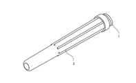
- FIG. 2 is a perspective view of the needle unit with the cap attached
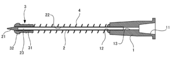
- FIG. 3 is a perspective view of the needle unit with the cap removed
- FIG. 4 is a cross-sectional view of the needle unit in FIG. 3, and FIG. FIG.
- the extending direction of the needle member shown in FIG. 5 is referred to as the axial direction.
- the left side of FIG. 4 is referred to as the front end side or the front side
- the right side is referred to as the base end side or the rear end side
- other drawings will be described based on this orientation.
- the present invention is not limited by this orientation.
- the needle unit 10 includes a base portion 1 attached to the nozzle 203 of the syringe 20 and a needle member 2 attached to the distal end side of the base portion 1.
- the needle unit 10 further includes a slide member 3 attached to the needle member 2, a spring member 4 that biases the slide member 3 toward the distal end side of the needle member 2, and a cap 5 that covers the needle member 2. ing.
- each member will be described in detail.
- the base portion 1 is formed of hard plastic, glass, metal, or the like, and is formed in a cylindrical shape whose outer diameter becomes thinner toward the tip.
- the recessed part 11 in which the nozzle 203 of the syringe 20 is inserted is formed in the base end part side of the base part 1.
- an insertion port 12 into which the needle member 2 is inserted is formed at the distal end of the base portion 1, and the insertion port 12 communicates with the distal end of the recess 11 through the communication path 13.
- the fixing method is not specifically limited.
- luer lock type fixing in addition to fixing by simply press-fitting, so-called luer lock type fixing is also possible.
- a wall having a female screw is provided around the nozzle 203, and the nozzle 203 and the base portion 1 are fixed by screwing a male screw formed on the outer peripheral surface of the base portion 1 into the female screw.
- the needle member 2 is a known member that is also called a bud needle, and is formed of a hard metal, plastic, or the like. If it demonstrates in detail, this needle member 2 will have the front-end
- the internal space 22 opens on the base end side and communicates with the insertion port 12 of the base portion 1.
- a needle hole 23 is formed in the side surface near the distal end of the needle member 2 (base end side with respect to the conical portion), and the needle hole 23 communicates with the internal space 22.
- the concave portion 11 of the base portion 1, the communication path 13, the internal space 22 of the needle member 2, and the needle hole 23 communicate with each other, and the medicine flowing from the needle hole 23 passes through the base portion 1 and the syringe 20. It is possible to flow in.
- the needle hole 23 is preferably formed at a position 3 to 10 mm from the distal end of the needle member 2, that is, closer to the base portion 1 side than the inclined surface of the conical portion of the distal end portion 21.
- the needle hole 23 is formed on the inclined surface of the conical portion of the distal end portion 21, so that the closing by the slide member 3 is incomplete as will be described later. Because it becomes a thing. On the other hand, if it exceeds 10 mm, there is a risk of hindering the collection of the drug.
- the needle hole 23 is preferably formed in a circular or elliptical shape with a diameter of about 0.5 to 1.2 mm, for example.
- a plurality of needle holes 23 can also be provided. In this case, in addition to arranging the needle holes 23 side by side in the axial direction, they can be arranged on the opposite side with the axis of the needle member 2 interposed therebetween. However, if there are too many needle holes 23, it cannot be closed by the slide member 3, and should be at least a number that can be covered by the slide member 3.
- a cylindrical slide member 3 is attached to the needle member 2, and the slide member 3 is movable in the axial direction along the needle member 2.
- the slide member 3 includes a columnar main body 31 and a columnar engagement portion 32 that is attached to the distal end side of the main body 31 and has a diameter larger than that of the main body 31.
- the needle member 2 is inserted through a through hole that penetrates the engaging portion 32.
- a coiled spring member (biasing member) 4 is attached between the rear end portion of the slide member 3 and the front end portion of the base portion 1.
- the slide member 3 is biased toward the distal end side of the needle member 2 by the spring member 4.
- the slide member 3 It is arranged near the tip (first position) and covers the needle hole 23.
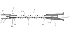
- the cap 5 is attached so as to cover the needle member 2
- the slide member 3 is pressed toward the base portion 1 by the cap 5, thereby compressing the spring member 4.
- the slide member 3 moves to the base part 1 side so as to expose the needle hole 23 (second position).
- the slide member 3 can employ a plastic such as thermoplastic elastomer, polyethylene, polypropylene, poly-4-methylpentene, polycarbonate, etc., but other resins having a low frictional force such as polytetrafluoroethylene and silicone resin can also be used. It can be used suitably. Further, if necessary, silicone coating, silicone coating, or the like can be performed. Moreover, it is preferable that the clearance gap between the inner wall surface of the through-hole of the slide member 3 and the side surface of the needle member 2 shall be larger than 0 mm and 50 micrometers or less, for example.
- the cap 5 is formed in a hollow cylindrical shape so as to cover the needle member 2, the front end side is closed, and the rear end side is opened. And the opening of a rear-end part is comprised so that the front-end
- the inner diameter of the small diameter portion 51 of the cap 5 is smaller than the outer diameter of the engaging portion 32 of the slide member 3, and the inner diameter of the large diameter portion 52 is larger than the outer diameter of the engaging portion 32. Therefore, as shown in FIG. 5, in a state where the cap 5 is attached to the base portion 1, the stepped portion 53 engages with the engaging portion 32 of the slide member 3 and presses it toward the base portion 1 side. It has become. That is, the slide member 3 moves from a position covering the needle hole 23 so that the needle hole 23 is exposed.
- the cap 5 can be formed of a general-purpose hard plastic such as polyethylene or polypropylene, and is preferably transparent or translucent so that the inside can be visually confirmed.
- a general-purpose hard plastic such as polyethylene or polypropylene
- the drug container 30 is generally called a vial, and is made of a glass bottle main body 301 and a bottle stopper (lid) that closes an opening formed in the upper portion of the bottle main body 301.
- the bottle body 301 is typically transparent or translucent.
- the bottle main body 301 is formed in a substantially cylindrical shape as a whole, and a neck portion 311 having a small diameter is formed on the upper portion thereof. Further, a flange portion 312 is formed above the neck portion 311, and the bottle stopper 302 is attached so as to cover the flange portion 312.
- the portion of the bottle stopper 302 that closes the upper opening of the bottle body 301 is made of an elastically deformable material such as rubber or elastomer, and can be pierced by the needle member 2 as will be described later. On the contrary, when the needle member 2 is pulled out from this portion, the needle hole formed by the piercing of the needle member 2 is closed almost instantly, though not completely, due to its elasticity. Further, the bottle cap 302 is wound and fixed to the flange portion 312 with an aluminum cap 303, and the aluminum cap 303 covers the entire portion except the central portion on the upper surface of the bottle cap 302. Therefore, when accessing the medicine container 30 using the syringe 20, the needle member 2 needs to be inserted into the bottle stopper 302 from the circular central portion on the upper surface thereof.
- an elastically deformable material such as rubber or elastomer
- the medicine accommodated in the medicine container 30 is not particularly limited, but for example, it is a medicine that can be a problem to be exposed to the outside.
- examples of such drugs are drugs that have cytotoxicity, and if exposed to them, those who handle them (mainly medical workers; hereinafter referred to as users) will have serious side effects or may be cytotoxic. It is a drug that may cause health damage or the like.
- examples of such drugs include antineoplastic agents, immunosuppressive agents, antiviral agents, antibiotics, radiopharmaceuticals and the like.
- Another example of a drug that can be a problem with exposure to the outside is a drug having odor or irritation.
- the medicine includes powder and the like.
- the liquid mixture is put into the medicine container 30 using the needle unit 10 and the syringe 20 before the suction.
- the drug is dissolved in the drug container 30 by the mixed solution.
- the mixed solution is physiological saline, Ringer's solution, distilled water, or the like, and is a solution for diluting or dissolving the drug.
- the base 1 of the needle unit 10 is fixed to the nozzle 203 of the syringe 20.
- the plunger 202 of the syringe 20 is in a state where it is pushed into the outer cylinder 201, that is, in a state where the gasket 204 is in close contact with the tip of the outer cylinder 201.
- the cap 5 is attached to the base portion 1, and the plunger 202 is moved backward to suck air into the outer cylinder 201.
- the cap 5 is removed from the base 1.
- the load that presses the slide member 3 toward the base portion 1 is released, so that the slide member 3 is urged toward the distal end side by the spring member 4 to cover the needle hole 23 as shown in FIG. Placed in position.
- the needle member 2 is inserted into the bottle stopper 302 of the medicine container 30, and the medicine is sucked while air is sent into the medicine container 30 by a pumping operation.
- the slide member 3 is pressed by the bottle stopper 302 and moves to the base portion 1 side. That is, since the slide member 3 can move along the needle member 2, it does not hinder the needle member 2 from being inserted into the bottle stopper 302.
- the needle member 2 is removed from the bottle stopper 302.
- the slide member 3 that has been pushed in by the bottle stopper 302 is released from being pressed by the bottle stopper 302, so that it is urged toward the distal end side by the spring member 4 to close the needle hole 23 as shown in FIG. 9.
- the slide member 3 immediately closes the needle hole 23, so that the sucked medicine can be prevented from leaking from the needle hole 23.
- the user inserts the needle member 2 into the bottle stopper of the mixed liquid container containing the mixed liquid and pushes the plunger 202.
- medical agent in the syringe 20 is inject
- medical agent is attracted
- the same thing may be used for the syringe 20 and you may change in the middle. Thereafter, the user carries the mixed liquid container containing the mixed chemical liquid to the patient and administers the mixed chemical liquid in the mixed liquid container to the patient by a method such as instillation.
- the slide member 3 that can move between the position for closing the needle hole 23 and the position for opening the needle hole 23 is provided along the needle member 2.
- the slide member 3 is biased by the spring member 4 so as to be disposed at a position where the needle hole 23 is closed.
- the slide member 3 is moved to a position where the needle hole is opened, and the internal space of the cap 5 communicates with the outside.
- the slide member 3 When the needle member 2 is inserted into the bottle stopper 302 of the medicine container 30, the slide member 3 is pressed toward the base portion 1 by the bottle stopper 302, so that the needle hole 23 is opened and the medicine can be sucked. Become. On the other hand, when the suction of the medicine is completed and the needle member 2 is pulled out from the bottle stopper 302, the pressing of the slide member 3 by the bottle stopper 302 is released, so that the slide member 3 is biased to the distal end side by the spring member 4. The needle hole 23 is immediately closed. Therefore, the aspirated medicine can be prevented from leaking from the needle hole 23.
- the step 53 is provided on the inner wall surface of the cap 5 in order to press the slide member 3 toward the base 1 when the cap 5 is attached to the base 1.
- the structure of may be sufficient.
- a protrusion (engaged part) is provided on the inner wall surface of the cap 5, the protrusion is engaged with the engagement part 32 of the slide member 3, and the slide member 3 is moved to the base part 1 side. it can.
- a pair of extending members 33 extending forward are attached to the distal end portion of the slide member 3.
- Each extending member 33 is formed in an arc shape in cross section, and the two extending members 33 surround the distal end portion 21 of the needle member 2 from the side surface. Thereby, when the slide member 3 closes the needle hole 23, the distal end portion 21 of the needle member 2 can be protected by the extending member 33.
- the front end surface of the internal space of the cap 5 presses both the extending members 33, thereby causing the slide member 3 to move to the base portion 1. Move to the side. As a result, the needle hole 23 is opened.
- the structure of the extending member 33 is not specifically limited, What is necessary is just a shape pressed by the front-end
- a gap is formed between the rear end portion of the cap 5 and the base portion 1 so that air can flow into the internal space of the cap 5, but air can flow into the internal space of the cap 5.
- Any other configuration may be used.
- a through-hole may be formed on the side surface of the cap 5 to allow air to flow in.
- the distal end portion 21 of the needle member 2 slightly protrudes from the distal end of the slide member 3 so that the position of the distal end portion 21 of the needle member 2 can be visually recognized.
- the position of the slide member 3 is adjusted so that the distal end portion 21 of the needle member 2 does not protrude from the slide member 3 so that the distal end portion 21 of the needle member 2 is accommodated in the slide member 3. You can also.
- the slide member 3 is formed of a transparent or translucent material, the position of the needle member 2 can be visually recognized even if the distal end portion 21 of the needle member 2 is covered with the slide member 3. .
- the configuration of the slide member 3 is not particularly limited, and is not particularly limited as long as it can move along the needle member 2 and can close the needle hole 23.
- the second position according to the present invention is not particularly limited as long as it is a position where the needle hole 23 is opened.
- the configuration of the base unit 1 is not particularly limited as long as it supports the needle member 2 and can be attached to the syringe 20.
- the biasing member of the present invention is not particularly limited as long as it can bias the slide member 3 from the position on the base portion 1 side to the position where the needle hole 23 is closed like the spring member of the above-described embodiment.
- a leaf spring can be used as the spring member.
- a pair of spring members 40 constituted by leaf springs are prepared, and the slide member 3 and the base portion 1 are connected by these. At this time, the two spring members 40 are disposed at symmetrical positions with the axis of the needle member 2 interposed therebetween.
- the cap 50 is not attached to the needle unit 10
- the two spring members 40 are in a state of extending almost straight without being curved.
- the cap 50 is formed so that the curved spring member 40 can be accommodated.
- the cap 50 according to this example also includes a small-diameter portion 510 that accommodates the distal end portion 21 of the needle member 2 and a large-diameter portion 520 closer to the base portion 1 than the above-described embodiment.
- the step part 530 is formed between these. Therefore, when the cap 50 is attached to the needle unit 10, the slide member 3 is pressed toward the base portion 1 by the step portion 530. At this time, each spring member 40 is curved so that the needle member 2 is separated, but the large-diameter portion 520 of the cap 50 is formed in a rectangular parallelepiped shape that can accommodate both curved spring members 40.
- the spring member 40 is constituted by the plate spring as described above, the following advantages are obtained. For example, if the spring member is coiled as in the above embodiment, when the needle member 2 as shown in FIG. 10 is pulled out from the state of being inserted into the bottle stopper 302 of the medicine container 30, the compressed spring member 4 There is a possibility that the slide member 3 jumps out of the tip of the needle member 2 due to the repulsion and comes off. On the other hand, when the spring member 40 is configured by a leaf spring as described above and the cap 50 is not attached to the needle unit 10, the slide member 3 is in the needle hole 23 at a position where the spring member 40 extends almost straight.
- the spring member 40 and the slide member 3 may be configured as separate members, or may be configured integrally with one material. Moreover, not only two such spring members 40 but also one or three or more can be provided.
- the slide member 3 and the base portion 1 can be connected by a deformable restricting member, for example, in the shape of the plate spring. If it does in this way, even if it uses the coil-shaped spring member 4, it can prevent that the slide member 3 detach
- plate spring will not be specifically limited if a spring function is exhibited with an elastic material with a restoring force, such as a metal and a plastic.
- Base part 2 Needle member 23: Needle hole 3: Slide member 33: Extension member 4: Spring member (biasing member) 40: Spring member (biasing member) 5: Cap 50: Cap 10: Needle unit 20: Syringe 51: Small diameter part 52: Large diameter part 53: Step part (engaged part) 510: Small diameter part 520: Large diameter part 530: Step part (engaged part)
Abstract
La présente invention concerne une unité d'aiguille montée sur une seringue médicale. Ladite unité d'aiguille comprend : un élément aiguille présentant un espace interne s'étendant longitudinalement, ledit élément aiguille présentant également un trou d'aiguille formé dans la surface latérale de l'extrémité avant de l'élément aiguille, l'élément aiguille présentant en outre une ouverture formée dans l'extrémité de base de l'élément aiguille, l'espace interne étant en communication avec l'extérieur à travers le trou d'aiguille et l'ouverture ; une section de base permettant de supporter l'extrémité de base de l'élément aiguille et de fournir une communication entre la seringue et l'espace interne de l'élément aiguille lorsqu'il est monté sur la seringue ; un élément coulissant mobile le long de la surface périphérique externe de l'élément aiguille et pouvant avoir une première position dans laquelle l'élément coulissant ferme le trou d'aiguille et une seconde position dans laquelle l'élément coulissant découvre le trou d'aiguille au niveau d'une position plus proche de l'extrémité de base que de la première position ; un élément de compression permettant de comprimer l'élément coulissant du côté de la seconde position vers le côté de la première position ; et un capuchon monté amovible sur la section de base de sorte à recouvrir l'élément aiguille.
Priority Applications (4)
| Application Number | Priority Date | Filing Date | Title |
|---|---|---|---|
| US15/746,951 US20190134316A1 (en) | 2015-07-24 | 2016-06-10 | Needle unit |
| CN201680043196.XA CN107847686A (zh) | 2015-07-24 | 2016-06-10 | 针组件 |
| JP2017531074A JPWO2017018076A1 (ja) | 2015-07-24 | 2016-06-10 | 針ユニット |
| EP16830181.0A EP3326675A4 (fr) | 2015-07-24 | 2016-06-10 | Unité d'aiguille |
Applications Claiming Priority (2)
| Application Number | Priority Date | Filing Date | Title |
|---|---|---|---|
| JP2015147250 | 2015-07-24 | ||
| JP2015-147250 | 2015-07-24 |
Publications (1)
| Publication Number | Publication Date |
|---|---|
| WO2017018076A1 true WO2017018076A1 (fr) | 2017-02-02 |
Family
ID=57884224
Family Applications (1)
| Application Number | Title | Priority Date | Filing Date |
|---|---|---|---|
| PCT/JP2016/067458 WO2017018076A1 (fr) | 2015-07-24 | 2016-06-10 | Unité d'aiguille |
Country Status (6)
| Country | Link |
|---|---|
| US (1) | US20190134316A1 (fr) |
| EP (1) | EP3326675A4 (fr) |
| JP (1) | JPWO2017018076A1 (fr) |
| CN (1) | CN107847686A (fr) |
| TW (1) | TW201703804A (fr) |
| WO (1) | WO2017018076A1 (fr) |
Cited By (2)
| Publication number | Priority date | Publication date | Assignee | Title |
|---|---|---|---|---|
| CN110811906A (zh) * | 2019-11-21 | 2020-02-21 | 江苏农牧科技职业学院 | 一种医学用阳性猪场中仔猪伪狂犬病超前免疫装置 |
| KR102658497B1 (ko) * | 2021-08-05 | 2024-04-17 | 장영환 | 약액통과 니들이 내장된 수동 주사기 조립체 |
Families Citing this family (1)
| Publication number | Priority date | Publication date | Assignee | Title |
|---|---|---|---|---|
| US11617806B2 (en) | 2018-10-30 | 2023-04-04 | Lg Electronics Inc. | Mask storage apparatus |
Citations (4)
| Publication number | Priority date | Publication date | Assignee | Title |
|---|---|---|---|---|
| US2876770A (en) * | 1955-10-10 | 1959-03-10 | Raymond A White | Shielded hypodermic syringe |
| US4139009A (en) * | 1976-11-23 | 1979-02-13 | Marcial Alvarez | Hypodermic needle assembly with retractable needle cover |
| US4790830A (en) * | 1985-04-01 | 1988-12-13 | Hamacher Edward N | Infusion needle |
| US4846809A (en) * | 1988-02-29 | 1989-07-11 | Winifred Sims | Needle tip protective device |
Family Cites Families (14)
| Publication number | Priority date | Publication date | Assignee | Title |
|---|---|---|---|---|
| US2634726A (en) * | 1952-01-30 | 1953-04-14 | Ralph D Hanson | Hypodermic needle |
| WO1984004673A1 (fr) * | 1983-05-20 | 1984-12-06 | Bengt Gustavsson | Dispositif pour le transfert d'une substance |
| US4804371A (en) * | 1987-05-06 | 1989-02-14 | Vaillancourt Vincent L | Post-injection needle sheath |
| US4725267A (en) * | 1987-05-06 | 1988-02-16 | Vaillancourt Vincent L | Post-injection needle sheath |
| US4887998A (en) * | 1987-12-14 | 1989-12-19 | Martin Catherine L | Hypodermic needle guard |
| US4915697A (en) * | 1988-03-16 | 1990-04-10 | Dupont Frank | Hypodermic needle assembly |
| US5478328A (en) * | 1992-05-22 | 1995-12-26 | Silverman; David G. | Methods of minimizing disease transmission by used hypodermic needles, and hypodermic needles adapted for carrying out the method |
| US5584818A (en) * | 1994-08-22 | 1996-12-17 | Morrison; David | Safety hypodermic needle and shielding cap assembly |
| US5549568A (en) * | 1994-08-22 | 1996-08-27 | Shields; Jack W. | Elastomeric needle shield and hub-cap |
| US5487733A (en) * | 1994-09-20 | 1996-01-30 | Becton, Dickinson And Company | Assembly with collapsible sheath and tip guard |
| JP3350809B2 (ja) * | 1997-09-30 | 2002-11-25 | 有限会社ナカムラ企画 | 差込植毛器 |
| US8617118B1 (en) * | 2008-11-04 | 2013-12-31 | Lloyd A. Marks | Safety needle and method of making same |
| US9414990B2 (en) * | 2013-03-15 | 2016-08-16 | Becton Dickinson and Company Ltd. | Seal system for cannula |
| CN203763664U (zh) * | 2014-03-13 | 2014-08-13 | 李宜 | 一种留置导管微量缓释输液装置 |
-
2016
- 2016-06-10 JP JP2017531074A patent/JPWO2017018076A1/ja active Pending
- 2016-06-10 US US15/746,951 patent/US20190134316A1/en not_active Abandoned
- 2016-06-10 CN CN201680043196.XA patent/CN107847686A/zh active Pending
- 2016-06-10 EP EP16830181.0A patent/EP3326675A4/fr not_active Withdrawn
- 2016-06-10 WO PCT/JP2016/067458 patent/WO2017018076A1/fr active Application Filing
- 2016-06-20 TW TW105119263A patent/TW201703804A/zh unknown
Patent Citations (4)
| Publication number | Priority date | Publication date | Assignee | Title |
|---|---|---|---|---|
| US2876770A (en) * | 1955-10-10 | 1959-03-10 | Raymond A White | Shielded hypodermic syringe |
| US4139009A (en) * | 1976-11-23 | 1979-02-13 | Marcial Alvarez | Hypodermic needle assembly with retractable needle cover |
| US4790830A (en) * | 1985-04-01 | 1988-12-13 | Hamacher Edward N | Infusion needle |
| US4846809A (en) * | 1988-02-29 | 1989-07-11 | Winifred Sims | Needle tip protective device |
Non-Patent Citations (1)
| Title |
|---|
| See also references of EP3326675A4 * |
Cited By (8)
| Publication number | Priority date | Publication date | Assignee | Title |
|---|---|---|---|---|
| CN110811906A (zh) * | 2019-11-21 | 2020-02-21 | 江苏农牧科技职业学院 | 一种医学用阳性猪场中仔猪伪狂犬病超前免疫装置 |
| CN110811906B (zh) * | 2019-11-21 | 2021-10-15 | 江苏农牧科技职业学院 | 一种医学用阳性猪场中仔猪伪狂犬病超前免疫装置 |
| KR102658497B1 (ko) * | 2021-08-05 | 2024-04-17 | 장영환 | 약액통과 니들이 내장된 수동 주사기 조립체 |
| KR102658498B1 (ko) * | 2021-08-05 | 2024-04-17 | 장영환 | 약액통과 니들이 내장된 자동 주사기 장치 |
| KR102658552B1 (ko) * | 2021-08-05 | 2024-04-18 | 장영환 | 니들 내장형 자동 주사기 장치 |
| KR102658550B1 (ko) * | 2021-08-05 | 2024-04-18 | 장영환 | 니들 내장형 수동 주사기 조립체 |
| KR102658549B1 (ko) * | 2021-08-05 | 2024-04-18 | 장영환 | 약액통과 니들이 내장된 자동 주사기 장치 |
| KR102658535B1 (ko) * | 2021-08-05 | 2024-04-18 | 장영환 | 약액통과 니들이 내장된 주사기 장치 |
Also Published As
| Publication number | Publication date |
|---|---|
| CN107847686A (zh) | 2018-03-27 |
| EP3326675A1 (fr) | 2018-05-30 |
| TW201703804A (zh) | 2017-02-01 |
| EP3326675A4 (fr) | 2019-02-13 |
| US20190134316A1 (en) | 2019-05-09 |
| JPWO2017018076A1 (ja) | 2018-05-10 |
Similar Documents
| Publication | Publication Date | Title |
|---|---|---|
| US20160235920A1 (en) | Single Use Device for Delivery of Cartridge Drugs | |
| KR101298462B1 (ko) | 약액 조제용 키트 | |
| ES2821653T3 (es) | Conjunto de jeringa con aguja retráctil | |
| CN104703639B (zh) | 注射器设备 | |
| US20070208296A1 (en) | Syringe Safety Device | |
| CN104415428A (zh) | 具有滑动前端连接件和可收回针的组合医疗装置 | |
| KR20070114721A (ko) | 게이트웨이 시스템 | |
| KR20180091078A (ko) | 의료용 주입기용 캡 | |
| EP2613823B1 (fr) | Aiguille à injection réutilisable pourvue d'un étui protecteur pour l'aiguille qui contient des agents de stérilisation et de lubrification et un système de guidage pour raccorder le pavillon de l'aiguille à un dispositif d'administration de médicament | |
| US8771236B2 (en) | Systems and methods for a medical syringe | |
| US20200139054A1 (en) | Safety needle with deformable cannula for injector pen | |
| WO2017018076A1 (fr) | Unité d'aiguille | |
| KR102277725B1 (ko) | 개선된 의료용 커넥터 | |
| US11311683B2 (en) | Self-retracting mechanized syringe and methods of use | |
| KR20160092813A (ko) | 바늘용 안전 캡 | |
| US20220160583A1 (en) | Fluid transfer system and components therefor | |
| JP2018531720A (ja) | フィルター注射器 | |
| KR102181488B1 (ko) | 의료용 주입기용 t자 형상의 캡 | |
| JP2014236906A (ja) | 針カバー、針アセンブリ、及び針付きシリンジ | |
| KR101536584B1 (ko) | 의료용 주사 바늘 및 이를 이용한 주사기 | |
| JP6096229B2 (ja) | 針アセンブリの作動方法 | |
| CN110612166A (zh) | 排放器和用于排放的方法 | |
| CN103998084A (zh) | 针座和用于一次性使用的针组件的处理装置 | |
| JP2014090805A (ja) | 針カバー、針アセンブリ及び針付きシリンジ | |
| MXPA97001608A (en) | A syringe of seguri |
Legal Events
| Date | Code | Title | Description |
|---|---|---|---|
| 121 | Ep: the epo has been informed by wipo that ep was designated in this application |
Ref document number: 16830181 Country of ref document: EP Kind code of ref document: A1 |
|
| ENP | Entry into the national phase |
Ref document number: 2017531074 Country of ref document: JP Kind code of ref document: A |
|
| NENP | Non-entry into the national phase |
Ref country code: DE |
|
| WWE | Wipo information: entry into national phase |
Ref document number: 2016830181 Country of ref document: EP |