WO2017014324A1 - 制御システム、作業機械、及び制御方法 - Google Patents
制御システム、作業機械、及び制御方法 Download PDFInfo
- Publication number
- WO2017014324A1 WO2017014324A1 PCT/JP2016/072448 JP2016072448W WO2017014324A1 WO 2017014324 A1 WO2017014324 A1 WO 2017014324A1 JP 2016072448 W JP2016072448 W JP 2016072448W WO 2017014324 A1 WO2017014324 A1 WO 2017014324A1
- Authority
- WO
- WIPO (PCT)
- Prior art keywords
- hydraulic
- pump
- flow rate
- cylinder
- pressure
- Prior art date
- Legal status (The legal status is an assumption and is not a legal conclusion. Google has not performed a legal analysis and makes no representation as to the accuracy of the status listed.)
- Ceased
Links
Images






Classifications
-
- E—FIXED CONSTRUCTIONS
- E02—HYDRAULIC ENGINEERING; FOUNDATIONS; SOIL SHIFTING
- E02F—DREDGING; SOIL-SHIFTING
- E02F9/00—Component parts of dredgers or soil-shifting machines, not restricted to one of the kinds covered by groups E02F3/00 - E02F7/00
- E02F9/20—Drives; Control devices
- E02F9/22—Hydraulic or pneumatic drives
- E02F9/2246—Control of prime movers, e.g. depending on the hydraulic load of work tools
-
- E—FIXED CONSTRUCTIONS
- E02—HYDRAULIC ENGINEERING; FOUNDATIONS; SOIL SHIFTING
- E02F—DREDGING; SOIL-SHIFTING
- E02F9/00—Component parts of dredgers or soil-shifting machines, not restricted to one of the kinds covered by groups E02F3/00 - E02F7/00
- E02F9/20—Drives; Control devices
- E02F9/22—Hydraulic or pneumatic drives
- E02F9/2221—Control of flow rate; Load sensing arrangements
- E02F9/2225—Control of flow rate; Load sensing arrangements using pressure-compensating valves
- E02F9/2228—Control of flow rate; Load sensing arrangements using pressure-compensating valves including an electronic controller
-
- E—FIXED CONSTRUCTIONS
- E02—HYDRAULIC ENGINEERING; FOUNDATIONS; SOIL SHIFTING
- E02F—DREDGING; SOIL-SHIFTING
- E02F9/00—Component parts of dredgers or soil-shifting machines, not restricted to one of the kinds covered by groups E02F3/00 - E02F7/00
- E02F9/20—Drives; Control devices
- E02F9/22—Hydraulic or pneumatic drives
- E02F9/2221—Control of flow rate; Load sensing arrangements
-
- E—FIXED CONSTRUCTIONS
- E02—HYDRAULIC ENGINEERING; FOUNDATIONS; SOIL SHIFTING
- E02F—DREDGING; SOIL-SHIFTING
- E02F3/00—Dredgers; Soil-shifting machines
- E02F3/04—Dredgers; Soil-shifting machines mechanically-driven
- E02F3/28—Dredgers; Soil-shifting machines mechanically-driven with digging tools mounted on a dipper- or bucket-arm, i.e. there is either one arm or a pair of arms, e.g. dippers, buckets
- E02F3/36—Component parts
- E02F3/42—Drives for dippers, buckets, dipper-arms or bucket-arms
- E02F3/422—Drive systems for bucket-arms, front-end loaders, dumpers or the like
-
- E—FIXED CONSTRUCTIONS
- E02—HYDRAULIC ENGINEERING; FOUNDATIONS; SOIL SHIFTING
- E02F—DREDGING; SOIL-SHIFTING
- E02F9/00—Component parts of dredgers or soil-shifting machines, not restricted to one of the kinds covered by groups E02F3/00 - E02F7/00
- E02F9/20—Drives; Control devices
- E02F9/22—Hydraulic or pneumatic drives
- E02F9/2221—Control of flow rate; Load sensing arrangements
- E02F9/2239—Control of flow rate; Load sensing arrangements using two or more pumps with cross-assistance
- E02F9/2242—Control of flow rate; Load sensing arrangements using two or more pumps with cross-assistance including an electronic controller
-
- E—FIXED CONSTRUCTIONS
- E02—HYDRAULIC ENGINEERING; FOUNDATIONS; SOIL SHIFTING
- E02F—DREDGING; SOIL-SHIFTING
- E02F9/00—Component parts of dredgers or soil-shifting machines, not restricted to one of the kinds covered by groups E02F3/00 - E02F7/00
- E02F9/20—Drives; Control devices
- E02F9/22—Hydraulic or pneumatic drives
- E02F9/2253—Controlling the travelling speed of vehicles, e.g. adjusting travelling speed according to implement loads, control of hydrostatic transmission
-
- E—FIXED CONSTRUCTIONS
- E02—HYDRAULIC ENGINEERING; FOUNDATIONS; SOIL SHIFTING
- E02F—DREDGING; SOIL-SHIFTING
- E02F9/00—Component parts of dredgers or soil-shifting machines, not restricted to one of the kinds covered by groups E02F3/00 - E02F7/00
- E02F9/20—Drives; Control devices
- E02F9/22—Hydraulic or pneumatic drives
- E02F9/2278—Hydraulic circuits
- E02F9/2292—Systems with two or more pumps
-
- E—FIXED CONSTRUCTIONS
- E02—HYDRAULIC ENGINEERING; FOUNDATIONS; SOIL SHIFTING
- E02F—DREDGING; SOIL-SHIFTING
- E02F9/00—Component parts of dredgers or soil-shifting machines, not restricted to one of the kinds covered by groups E02F3/00 - E02F7/00
- E02F9/20—Drives; Control devices
- E02F9/22—Hydraulic or pneumatic drives
- E02F9/2278—Hydraulic circuits
- E02F9/2296—Systems with a variable displacement pump
-
- F—MECHANICAL ENGINEERING; LIGHTING; HEATING; WEAPONS; BLASTING
- F15—FLUID-PRESSURE ACTUATORS; HYDRAULICS OR PNEUMATICS IN GENERAL
- F15B—SYSTEMS ACTING BY MEANS OF FLUIDS IN GENERAL; FLUID-PRESSURE ACTUATORS, e.g. SERVOMOTORS; DETAILS OF FLUID-PRESSURE SYSTEMS, NOT OTHERWISE PROVIDED FOR
- F15B11/00—Servomotor systems without provision for follow-up action; Circuits therefor
- F15B11/16—Servomotor systems without provision for follow-up action; Circuits therefor with two or more servomotors
- F15B11/161—Servomotor systems without provision for follow-up action; Circuits therefor with two or more servomotors with sensing of servomotor demand or load
- F15B11/163—Servomotor systems without provision for follow-up action; Circuits therefor with two or more servomotors with sensing of servomotor demand or load for sharing the pump output equally amongst users or groups of users, e.g. using anti-saturation, pressure compensation
-
- F—MECHANICAL ENGINEERING; LIGHTING; HEATING; WEAPONS; BLASTING
- F15—FLUID-PRESSURE ACTUATORS; HYDRAULICS OR PNEUMATICS IN GENERAL
- F15B—SYSTEMS ACTING BY MEANS OF FLUIDS IN GENERAL; FLUID-PRESSURE ACTUATORS, e.g. SERVOMOTORS; DETAILS OF FLUID-PRESSURE SYSTEMS, NOT OTHERWISE PROVIDED FOR
- F15B11/00—Servomotor systems without provision for follow-up action; Circuits therefor
- F15B11/16—Servomotor systems without provision for follow-up action; Circuits therefor with two or more servomotors
- F15B11/17—Servomotor systems without provision for follow-up action; Circuits therefor with two or more servomotors using two or more pumps
-
- F—MECHANICAL ENGINEERING; LIGHTING; HEATING; WEAPONS; BLASTING
- F15—FLUID-PRESSURE ACTUATORS; HYDRAULICS OR PNEUMATICS IN GENERAL
- F15B—SYSTEMS ACTING BY MEANS OF FLUIDS IN GENERAL; FLUID-PRESSURE ACTUATORS, e.g. SERVOMOTORS; DETAILS OF FLUID-PRESSURE SYSTEMS, NOT OTHERWISE PROVIDED FOR
- F15B13/00—Details of servomotor systems ; Valves for servomotor systems
- F15B13/02—Fluid distribution or supply devices characterised by their adaptation to the control of servomotors
-
- F—MECHANICAL ENGINEERING; LIGHTING; HEATING; WEAPONS; BLASTING
- F15—FLUID-PRESSURE ACTUATORS; HYDRAULICS OR PNEUMATICS IN GENERAL
- F15B—SYSTEMS ACTING BY MEANS OF FLUIDS IN GENERAL; FLUID-PRESSURE ACTUATORS, e.g. SERVOMOTORS; DETAILS OF FLUID-PRESSURE SYSTEMS, NOT OTHERWISE PROVIDED FOR
- F15B19/00—Testing; Calibrating; Fault detection or monitoring; Simulation or modelling of fluid-pressure systems or apparatus not otherwise provided for
- F15B19/007—Simulation or modelling
-
- F—MECHANICAL ENGINEERING; LIGHTING; HEATING; WEAPONS; BLASTING
- F16—ENGINEERING ELEMENTS AND UNITS; GENERAL MEASURES FOR PRODUCING AND MAINTAINING EFFECTIVE FUNCTIONING OF MACHINES OR INSTALLATIONS; THERMAL INSULATION IN GENERAL
- F16H—GEARING
- F16H61/00—Control functions within control units of change-speed- or reversing-gearings for conveying rotary motion ; Control of exclusively fluid gearing, friction gearing, gearings with endless flexible members or other particular types of gearing
- F16H61/38—Control of exclusively fluid gearing
- F16H61/40—Control of exclusively fluid gearing hydrostatic
- F16H61/4008—Control of circuit pressure
-
- F—MECHANICAL ENGINEERING; LIGHTING; HEATING; WEAPONS; BLASTING
- F16—ENGINEERING ELEMENTS AND UNITS; GENERAL MEASURES FOR PRODUCING AND MAINTAINING EFFECTIVE FUNCTIONING OF MACHINES OR INSTALLATIONS; THERMAL INSULATION IN GENERAL
- F16H—GEARING
- F16H61/00—Control functions within control units of change-speed- or reversing-gearings for conveying rotary motion ; Control of exclusively fluid gearing, friction gearing, gearings with endless flexible members or other particular types of gearing
- F16H61/38—Control of exclusively fluid gearing
- F16H61/40—Control of exclusively fluid gearing hydrostatic
- F16H61/46—Automatic regulation in accordance with output requirements
- F16H61/47—Automatic regulation in accordance with output requirements for achieving a target output speed
-
- F—MECHANICAL ENGINEERING; LIGHTING; HEATING; WEAPONS; BLASTING
- F15—FLUID-PRESSURE ACTUATORS; HYDRAULICS OR PNEUMATICS IN GENERAL
- F15B—SYSTEMS ACTING BY MEANS OF FLUIDS IN GENERAL; FLUID-PRESSURE ACTUATORS, e.g. SERVOMOTORS; DETAILS OF FLUID-PRESSURE SYSTEMS, NOT OTHERWISE PROVIDED FOR
- F15B2211/00—Circuits for servomotor systems
- F15B2211/20—Fluid pressure source, e.g. accumulator or variable axial piston pump
- F15B2211/205—Systems with pumps
- F15B2211/2053—Type of pump
- F15B2211/20546—Type of pump variable capacity
-
- F—MECHANICAL ENGINEERING; LIGHTING; HEATING; WEAPONS; BLASTING
- F15—FLUID-PRESSURE ACTUATORS; HYDRAULICS OR PNEUMATICS IN GENERAL
- F15B—SYSTEMS ACTING BY MEANS OF FLUIDS IN GENERAL; FLUID-PRESSURE ACTUATORS, e.g. SERVOMOTORS; DETAILS OF FLUID-PRESSURE SYSTEMS, NOT OTHERWISE PROVIDED FOR
- F15B2211/00—Circuits for servomotor systems
- F15B2211/20—Fluid pressure source, e.g. accumulator or variable axial piston pump
- F15B2211/205—Systems with pumps
- F15B2211/20576—Systems with pumps with multiple pumps
-
- F—MECHANICAL ENGINEERING; LIGHTING; HEATING; WEAPONS; BLASTING
- F15—FLUID-PRESSURE ACTUATORS; HYDRAULICS OR PNEUMATICS IN GENERAL
- F15B—SYSTEMS ACTING BY MEANS OF FLUIDS IN GENERAL; FLUID-PRESSURE ACTUATORS, e.g. SERVOMOTORS; DETAILS OF FLUID-PRESSURE SYSTEMS, NOT OTHERWISE PROVIDED FOR
- F15B2211/00—Circuits for servomotor systems
- F15B2211/20—Fluid pressure source, e.g. accumulator or variable axial piston pump
- F15B2211/275—Control of the prime mover, e.g. hydraulic control
-
- F—MECHANICAL ENGINEERING; LIGHTING; HEATING; WEAPONS; BLASTING
- F15—FLUID-PRESSURE ACTUATORS; HYDRAULICS OR PNEUMATICS IN GENERAL
- F15B—SYSTEMS ACTING BY MEANS OF FLUIDS IN GENERAL; FLUID-PRESSURE ACTUATORS, e.g. SERVOMOTORS; DETAILS OF FLUID-PRESSURE SYSTEMS, NOT OTHERWISE PROVIDED FOR
- F15B2211/00—Circuits for servomotor systems
- F15B2211/30—Directional control
- F15B2211/305—Directional control characterised by the type of valves
- F15B2211/30525—Directional control valves, e.g. 4/3-directional control valve
- F15B2211/3053—In combination with a pressure compensating valve
- F15B2211/3054—In combination with a pressure compensating valve the pressure compensating valve is arranged between directional control valve and output member
-
- F—MECHANICAL ENGINEERING; LIGHTING; HEATING; WEAPONS; BLASTING
- F15—FLUID-PRESSURE ACTUATORS; HYDRAULICS OR PNEUMATICS IN GENERAL
- F15B—SYSTEMS ACTING BY MEANS OF FLUIDS IN GENERAL; FLUID-PRESSURE ACTUATORS, e.g. SERVOMOTORS; DETAILS OF FLUID-PRESSURE SYSTEMS, NOT OTHERWISE PROVIDED FOR
- F15B2211/00—Circuits for servomotor systems
- F15B2211/30—Directional control
- F15B2211/305—Directional control characterised by the type of valves
- F15B2211/3056—Assemblies of multiple valves
- F15B2211/3059—Assemblies of multiple valves having multiple valves for multiple output members
- F15B2211/30595—Assemblies of multiple valves having multiple valves for multiple output members with additional valves between the groups of valves for multiple output members
-
- F—MECHANICAL ENGINEERING; LIGHTING; HEATING; WEAPONS; BLASTING
- F15—FLUID-PRESSURE ACTUATORS; HYDRAULICS OR PNEUMATICS IN GENERAL
- F15B—SYSTEMS ACTING BY MEANS OF FLUIDS IN GENERAL; FLUID-PRESSURE ACTUATORS, e.g. SERVOMOTORS; DETAILS OF FLUID-PRESSURE SYSTEMS, NOT OTHERWISE PROVIDED FOR
- F15B2211/00—Circuits for servomotor systems
- F15B2211/40—Flow control
- F15B2211/405—Flow control characterised by the type of flow control means or valve
-
- F—MECHANICAL ENGINEERING; LIGHTING; HEATING; WEAPONS; BLASTING
- F15—FLUID-PRESSURE ACTUATORS; HYDRAULICS OR PNEUMATICS IN GENERAL
- F15B—SYSTEMS ACTING BY MEANS OF FLUIDS IN GENERAL; FLUID-PRESSURE ACTUATORS, e.g. SERVOMOTORS; DETAILS OF FLUID-PRESSURE SYSTEMS, NOT OTHERWISE PROVIDED FOR
- F15B2211/00—Circuits for servomotor systems
- F15B2211/60—Circuit components or control therefor
- F15B2211/63—Electronic controllers
- F15B2211/6303—Electronic controllers using input signals
- F15B2211/6306—Electronic controllers using input signals representing a pressure
- F15B2211/6309—Electronic controllers using input signals representing a pressure the pressure being a pressure source supply pressure
-
- F—MECHANICAL ENGINEERING; LIGHTING; HEATING; WEAPONS; BLASTING
- F15—FLUID-PRESSURE ACTUATORS; HYDRAULICS OR PNEUMATICS IN GENERAL
- F15B—SYSTEMS ACTING BY MEANS OF FLUIDS IN GENERAL; FLUID-PRESSURE ACTUATORS, e.g. SERVOMOTORS; DETAILS OF FLUID-PRESSURE SYSTEMS, NOT OTHERWISE PROVIDED FOR
- F15B2211/00—Circuits for servomotor systems
- F15B2211/60—Circuit components or control therefor
- F15B2211/63—Electronic controllers
- F15B2211/6303—Electronic controllers using input signals
- F15B2211/6306—Electronic controllers using input signals representing a pressure
- F15B2211/6313—Electronic controllers using input signals representing a pressure the pressure being a load pressure
-
- F—MECHANICAL ENGINEERING; LIGHTING; HEATING; WEAPONS; BLASTING
- F15—FLUID-PRESSURE ACTUATORS; HYDRAULICS OR PNEUMATICS IN GENERAL
- F15B—SYSTEMS ACTING BY MEANS OF FLUIDS IN GENERAL; FLUID-PRESSURE ACTUATORS, e.g. SERVOMOTORS; DETAILS OF FLUID-PRESSURE SYSTEMS, NOT OTHERWISE PROVIDED FOR
- F15B2211/00—Circuits for servomotor systems
- F15B2211/60—Circuit components or control therefor
- F15B2211/63—Electronic controllers
- F15B2211/6303—Electronic controllers using input signals
- F15B2211/6333—Electronic controllers using input signals representing a state of the pressure source, e.g. swash plate angle
-
- F—MECHANICAL ENGINEERING; LIGHTING; HEATING; WEAPONS; BLASTING
- F15—FLUID-PRESSURE ACTUATORS; HYDRAULICS OR PNEUMATICS IN GENERAL
- F15B—SYSTEMS ACTING BY MEANS OF FLUIDS IN GENERAL; FLUID-PRESSURE ACTUATORS, e.g. SERVOMOTORS; DETAILS OF FLUID-PRESSURE SYSTEMS, NOT OTHERWISE PROVIDED FOR
- F15B2211/00—Circuits for servomotor systems
- F15B2211/60—Circuit components or control therefor
- F15B2211/665—Methods of control using electronic components
- F15B2211/6652—Control of the pressure source, e.g. control of the swash plate angle
-
- F—MECHANICAL ENGINEERING; LIGHTING; HEATING; WEAPONS; BLASTING
- F15—FLUID-PRESSURE ACTUATORS; HYDRAULICS OR PNEUMATICS IN GENERAL
- F15B—SYSTEMS ACTING BY MEANS OF FLUIDS IN GENERAL; FLUID-PRESSURE ACTUATORS, e.g. SERVOMOTORS; DETAILS OF FLUID-PRESSURE SYSTEMS, NOT OTHERWISE PROVIDED FOR
- F15B2211/00—Circuits for servomotor systems
- F15B2211/60—Circuit components or control therefor
- F15B2211/665—Methods of control using electronic components
- F15B2211/6654—Flow rate control
Definitions
- a control method for controlling a work machine and a work machine including a plurality of hydraulic cylinders for driving the work machine, wherein the hydraulic oil supplied to the hydraulic cylinder is a first hydraulic pressure. Discharging from the pump and the second hydraulic pump, obtaining cylinder pressure data indicating the pressure of the hydraulic oil in the hydraulic cylinder, and operating amount data of an operating device operated to drive the hydraulic cylinder Acquiring the first hydraulic pressure in a separated state in which a passage connecting the first hydraulic pump and the second hydraulic pump is closed by an opening and closing device based on the acquisition and the cylinder pressure data and the operation amount data.
- a control system a work machine, and a control method that can control a work machine with sufficient speed and responsiveness are provided.
- the upper-part turning body 2 can turn around the turning axis RX.
- the upper swing body 2 includes a cab 6 in which an operator is boarded and a machine room 7.
- a driver's seat 6S on which an operator is seated is provided in the cab 6.
- the machine room 7 is disposed behind the cab 6.
- At least a part of the drive device 4 including the engine and the hydraulic pump is disposed in the machine room 7.
- the lower traveling body 3 has a pair of crawlers 8.
- the hydraulic excavator 100 travels by the rotation of the crawler 8.
- the lower traveling body 3 may be a wheel (tire).
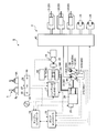
- the drive device 4 includes an engine 26 that is a drive source, a generator motor 27, and a hydraulic pump 30 that discharges hydraulic oil.
- the engine 26 is, for example, a diesel engine.
- the generator motor 27 is, for example, a switched reluctance motor.
- the generator motor 27 may be a PM (Permanent Magnet) motor.
- the hydraulic pump 30 is a variable displacement hydraulic pump. In the present embodiment, the hydraulic pump 30 is a swash plate hydraulic pump.
- the hydraulic pump 30 includes a first hydraulic pump 31 and a second hydraulic pump 32.
- the output shaft of the engine 26 is mechanically coupled to the generator motor 27 and the hydraulic pump 30. When the engine 26 is driven, the generator motor 27 and the hydraulic pump 30 are operated.
- the generator motor 27 may be mechanically directly connected to the output shaft of the engine 26 or may be connected to the output shaft of the engine 26 via a power transmission mechanism such as PTO (Power Take Off).
- PTO Power Take Off
- the hybrid controller 17 exchanges DC power between the transformer 14C and the first inverter 15G and the second inverter 15R. In addition, the hybrid controller 17 exchanges DC power between the transformer 14C and the battery 14.
- the electric swing motor 25 operates based on the electric power supplied from the generator motor 27 or the battery 14 and generates power for turning the upper swing body 2.
- the electric turning motor 25 is, for example, an embedded magnet synchronous electric turning motor.
- a rotation sensor 16 is provided in the electric turning motor 25.
- the rotation sensor 16 is, for example, a resolver or a rotary encoder. The rotation sensor 16 detects the rotation angle or rotation speed of the electric swing motor 25.
- the electric swing motor 25 generates regenerative energy during deceleration.
- the battery 14 is charged with regenerative energy (electric energy) generated by the electric swing motor 25.
- the capacitor 14 may be an electric double layer capacitor or a secondary battery such as a nickel metal hydride battery or a lithium ion battery.
- the driving device 4 operates based on the operation of the operating device 5 provided in the cab 6.
- the operation amount of the operation device 5 is detected by the operation amount detection unit 28.
- the operation amount detector 28 includes a pressure sensor.
- the pilot oil pressure generated according to the operation amount of the operation device 5 is detected by the operation amount detection unit 28.
- the operation amount detection unit 28 converts the detection signal of the pressure sensor into the operation amount of the operation device 5.
- the operation amount detection unit 28 may include an electrical sensor such as a potentiometer.
- the operation amount detector 28 detects an electric signal generated according to the operation amount of the operation device 5.
- the pump controller 19 calculates the pump capacity (cc / rev) of the hydraulic pump 30 based on the detection signal of the swash plate angle sensor 30S.
- the hydraulic pump 30 is provided with a servo mechanism that drives the swash plate 30A.
- the pump controller 19 controls the servo mechanism to adjust the swash plate angle.
- the hydraulic circuit 40 is provided with a pressure sensor 84 and a pressure sensor 85 for detecting the pressure of hydraulic fluid discharged from the hydraulic pump 30. Detection signals from the pressure sensor 84 and the pressure sensor 85 are output to the pump controller 19.
- the engine controller 18 and the pump controller 19 are connected by an in-vehicle LAN (Local Area Network) such as CAN (Controller Area Network).
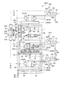
- FIG. 3 is a diagram illustrating an example of the hydraulic circuit 40 of the drive device 4 according to the present embodiment.
- the drive device 4 is supplied to the bucket cylinder 21, the arm cylinder 22, the boom cylinder 23, the first hydraulic pump 31 that discharges hydraulic oil supplied to the bucket cylinder 21 and the arm cylinder 22, and the boom cylinder 23.
- a second hydraulic pump 32 that discharges hydraulic oil.
- the hydraulic fluid discharged from the first hydraulic pump 31 and the second hydraulic pump 32 flows through the hydraulic circuit 40.
- the hydraulic circuit 40 includes a first pump passage 41 connected to the first hydraulic pump 31 and a second pump passage 42 connected to the second hydraulic pump 32.
- the hydraulic circuit 40 includes a first supply channel 43 and a second supply channel 44 connected to the first pump channel 41, and a third supply channel 45 and a fourth supply connected to the second pump channel 42. And a flow path 46.
- the hydraulic circuit 40 includes a main operation valve 60 that adjusts the direction and flow rate of hydraulic oil supplied to the hydraulic cylinder 20 based on pilot hydraulic pressure generated by operating the operation device 5.
- the main operation valve 60 includes a first main operation valve 61 that adjusts the direction and flow rate of the hydraulic oil supplied to the bucket cylinder 21, and a second main operation that adjusts the direction and flow rate of the hydraulic oil supplied to the arm cylinder 22. It includes a valve 62 and a third main operation valve 63 that adjusts the direction and flow rate of hydraulic oil supplied to the boom cylinder 23.
- the cap side space of the hydraulic cylinder 20 is a space between the cylinder head cover and the piston.
- the rod side space of the hydraulic cylinder 20 is a space in which the piston rod is disposed.
- the hydraulic oil is supplied to the cap side space 21C of the bucket cylinder 21 and the bucket cylinder 21 extends, whereby the bucket 11 performs excavation.
- the hydraulic oil is supplied to the rod-side space 21L of the bucket cylinder 21, and the bucket 11 performs a dumping operation when the bucket cylinder 21 is retracted.
- the work machine 1 is operated by operating the operation device 5.
- the operation device 5 includes a right operation lever 5R disposed on the right side of an operator seated on the driver's seat 6S and a left operation lever 5L disposed on the left side.
- the boom 13 is lowered or raised.
- the bucket 11 performs excavation operation or dump operation.
- the arm 12 performs a dumping operation or an excavating operation.
- the upper swing body 2 turns left or right.
- the upper swing body 2 may turn right or left when the left operation lever 5L is moved in the front-rear direction, and the arm 12 may perform dumping operation or excavation operation when the left operation lever 5L is moved in the left-right direction.
- the first main operation valve 61 is a directional control valve that adjusts the direction and flow rate of hydraulic oil supplied from the first hydraulic pump 31 to the bucket cylinder 21.
- the second main operation valve 62 is a direction control valve that adjusts the direction and flow rate of hydraulic oil supplied from the first hydraulic pump 31 to the arm cylinder 22.
- the third main operation valve 63 is a direction control valve that adjusts the direction and flow rate of the hydraulic oil supplied from the second hydraulic pump 32 to the boom cylinder 23.
- the first main operation valve 61 is a slide spool type directional control valve.
- the spool of the first main operation valve 61 stops the supply of hydraulic oil to the bucket cylinder 21 to stop the bucket cylinder 21, and the first branch flow so that the hydraulic oil is supplied to the cap side space 21C.
- the second position PT2 that connects the path 21B and retracts the bucket cylinder 21 is movable.
- the first main operation valve 61 is operated so that the bucket cylinder 21 is at least one of a stopped state, an extended state, and a retracted state.
- the third main operation valve 63 is operated by the operation device 5.
- the pilot hydraulic pressure acts on the third main operation valve 63, and the direction and flow rate of the hydraulic oil supplied from the third main operation valve 63 to the boom cylinder 23 are determined.
- the third main operation valve 63 moves the spool based on the pilot oil pressure generated when the operation device 5 is operated, and adjusts the direction and flow rate of the hydraulic oil supplied to the boom cylinder 23.
- the boom cylinder 23 operates in a moving direction corresponding to the direction of the hydraulic oil supplied to the boom cylinder 23, and the boom cylinder 23 operates at a cylinder speed corresponding to the flow rate of the hydraulic oil supplied to the boom cylinder 23.
- the operation amount detection unit 28 includes a pressure sensor 86 that detects a pilot oil pressure for operating the first main operation valve 61, a pressure sensor 87 that detects a pilot oil pressure for operating the second main operation valve 62, And a pressure sensor 88 that detects pilot oil pressure for operating the three main operation valves 63.
- the operation amount detector 28 calculates the operation amount of the operation device 5 for driving the bucket cylinder 21 based on the detection signal of the pressure sensor 86.
- the value of the detection signal of the pressure sensor 86 correlates with the operation amount of the operating device 5.
- the operation amount detection unit 28 stores correlation data indicating the relationship between the value of the detection signal from the pressure sensor 86 and the operation amount of the operation device 5.
- the operation amount detector 28 calculates the operation amount of the operation device 5 for driving the bucket cylinder 21 based on the detection signal of the pressure sensor 86 and the correlation data.
- the operation amount detector 28 calculates the operation amount of the operation device 5 for driving the arm cylinder 22 based on the detection signal of the pressure sensor 87.
- the operation amount detection unit 28 calculates the operation amount of the operation device 5 for driving the boom cylinder 23 based on the detection signal of the pressure sensor 88.
- the bucket 11 When the bucket cylinder 21 operates, the bucket 11 is driven based on the moving direction of the bucket cylinder 21 and the cylinder speed.
- the arm cylinder 22 When the arm cylinder 22 operates, the arm 12 is driven based on the moving direction of the arm cylinder 22 and the cylinder speed.
- the boom 13 By operating the boom cylinder 23, the boom 13 is driven based on the moving direction and the cylinder speed of the boom cylinder 23.
- the hydraulic oil discharged from the bucket cylinder 21, the arm cylinder 22, and the boom cylinder 23 is discharged to the tank 54 via the discharge flow path 53.
- the discharge flow path 53 is provided with a relief valve 90 that prevents the pressure of the hydraulic oil in the hydraulic circuit 40 from increasing.
- the relief valve 90 is activated, and the hydraulic oil is discharged from the hydraulic circuit 40 via the relief valve 90.
- the first pump flow path 41 and the second pump flow path 42 are connected by a merging flow path 55.
- the merge channel 55 is a passage that connects the first hydraulic pump 31 and the second hydraulic pump 32.
- the merging channel 55 connects the first hydraulic pump 31 and the second hydraulic pump 32 via the first pump channel 41 and the second pump channel 42.
- the hydraulic oil discharged from the first hydraulic pump 31 passes through the first pump channel 41, the first main operation valve 61, and the second main operation valve 62.
- the bucket cylinder 21 and the arm cylinder 22 are supplied.
- the hydraulic oil discharged from the second hydraulic pump 32 is transferred to the boom cylinder 23 via the second pump flow path 42 and the third main operation valve 63. Supplied.
- the second merging / dividing valve 68 supplies hydraulic oil supplied to the respective axes of the bucket cylinder 21 (first axis), the arm cylinder 22 (second axis), and the boom cylinder 23 (third axis) by the shuttle valve 80.
- the load sensing pressure is a pilot oil pressure used for pressure compensation.
- the maximum LS pressure between the first shaft and the second shaft causes the pressure compensation valve 70 of the first shaft and the second shaft and the servo mechanism 31B of the first hydraulic pump 31.
- LS pressure of the third axis is supplied to the pressure compensation valve 70 of the third axis and the servo mechanism 32B of the second hydraulic pump 32.
- a pressure sensor 81C is provided in the first bucket channel 21A.
- a pressure sensor 81L is provided in the second bucket channel 21B.
- the pressure sensor 81C detects the pressure in the cap side space 21C of the bucket cylinder 21.
- the pressure sensor 81L detects the pressure in the rod side space 21L of the bucket cylinder 21.
- the cylinder pressure data acquisition unit 191 acquires cylinder pressure data of the bucket cylinder 21 from the pressure sensor 81C and the pressure sensor 81L.
- the cylinder pressure data acquisition unit 191 acquires cylinder pressure data of the arm cylinder 22 from the pressure sensor 82C and the pressure sensor 82L.
- the cylinder pressure data acquisition unit 191 acquires cylinder pressure data of the boom cylinder 23 from the pressure sensor 83C and the pressure sensor 83L.
- the operation amount data acquisition unit 192 acquires operation amount data indicating the operation amount of the operation device 5 that is operated to drive the bucket cylinder 21.
- the operation amount data acquisition unit 192 acquires operation amount data indicating the operation amount of the operation device 5 operated to drive the arm cylinder 22.
- the operation amount data acquisition unit 192 acquires operation amount data indicating the operation amount of the operation device 5 operated to drive the boom cylinder 23.
- the operation amount data acquisition unit 192 acquires operation amount data from the operation amount detection unit 28 including the pressure sensors 86, 87, 88.
- Qbk Qdbk ⁇ ⁇ ⁇ (PP ⁇ LAbk) / ⁇ PL ⁇ (2)
- Qa Qda ⁇ ⁇ ⁇ (PP ⁇ LAa) / ⁇ PL ⁇ (3)
- Qb Qdb ⁇ ⁇ ⁇ (PP ⁇ LAb) / ⁇ PL ⁇ (4)
- the pump flow rate calculation unit 193 when the pressure PP of the hydraulic oil discharged from the hydraulic pump 30 is unknown, the pump flow rate calculation unit 193 repeatedly performs numerical calculation so that the following formula (5) converges.
- the pressure PP is calculated based on the distribution flow rates Qbk, Qa, Qb when the equation (5) converges.
- the pump flow rate calculation unit 193 calculates the first pump flow rate of the first hydraulic pump 31 and the second hydraulic pump 32 based on the distribution flow rates Qbk, Qa, and Qb. 2 Calculate the pump flow rate. That is, in the separated state in which the merging flow path 55 is closed, the first pump flow rate is driven based on the operation amount of the operating device 5, so that the hydraulic oil required by the bucket cylinder 21 of the first hydraulic cylinder group is required. It is determined based on the distribution flow rate Qbk and the distribution flow rate Qa of the hydraulic oil required for the arm cylinder 22.
- the lever stroke Lvsa is a stroke of the operation lever when the operation device 5 is operated to operate the arm 12.
- the lever stroke Lvsb is a stroke of the operation lever when the operation device 5 is operated to operate the boom 13.
- the operation amount data acquisition unit 192 acquires operation amount data of the operation device 5 operated to drive the hydraulic cylinder 20 (step S30). As shown in FIG. 7, the operation amount for operating the arm cylinder 22 is the lever stroke Lvsa, and the operation amount for operating the boom cylinder 23 is the lever stroke Lvsb.
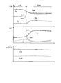
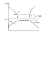
- FIG. 8 is a diagram illustrating an example in which the flow rates of the hydraulic pump 30 and the hydraulic cylinder 20, the discharge pressure of the hydraulic pump 30, and the lever stroke according to the comparative example change with time.
- FIG. 8 shows an example in which the flow rate of the hydraulic oil discharged from the hydraulic pump 30 including the first hydraulic pump 31 and the second hydraulic pump 32 is adjusted based on the pump pressure of the hydraulic oil discharged from the hydraulic pump 30. Show.
- the estimated value Qag of the flow rate of the hydraulic oil supplied to the arm cylinder 22 does not match the true value Qar when the transition is made from the merged state to the separated state.
- the estimated value Qbg and the true value Qbr of the flow rate of the supplied hydraulic oil do not match.
- the pump control unit 194 controls the first hydraulic pump 31 and the second hydraulic pump 32 based on the relief flow rate Qz calculated by the relief flow rate calculation unit 195.
- the pump control unit 194 controls the hydraulic pump 30 so that hydraulic oil that is larger by the relief flow rate Qz than the distribution flow rate Q necessary for the operation of the hydraulic cylinder 20 is discharged from the hydraulic pump 30.
- the flow rate of hydraulic oil required by the hydraulic cylinder 20 is accurately estimated by considering the relief flow rate Qz.
- the pump control unit 194 controls the first hydraulic pump 31 and the second hydraulic pump 32 so that the hydraulic oil having a flow rate required by the hydraulic cylinder 20 is discharged from the first hydraulic pump 31 and the second hydraulic pump 32. be able to. That is, in the relief state, the relief flow rate Qz of the hydraulic oil discharged from the relief valve 90 in the merged state is estimated, and the first hydraulic pump 31 and the first hydraulic pump 31 are discharged so that the estimated relief flow rate Qz is discharged. 2
- the hydraulic pump 32 is controlled. In the relief state, a pump flow rate equivalent to that in the merged state is ensured. A decrease in the response of the flow rate of the hydraulic oil supplied to the hydraulic cylinder 20 when the relief state is released is suppressed.
Landscapes
- Engineering & Computer Science (AREA)
- General Engineering & Computer Science (AREA)
- Mining & Mineral Resources (AREA)
- Civil Engineering (AREA)
- Structural Engineering (AREA)
- Physics & Mathematics (AREA)
- Fluid Mechanics (AREA)
- Mechanical Engineering (AREA)
- Fluid-Pressure Circuits (AREA)
- Operation Control Of Excavators (AREA)
Abstract
Description
[作業機械]
図1は、本実施形態に係る作業機械100の一例を示す斜視図である。本実施形態においては、作業機械100がハイブリッド方式の油圧ショベルである例について説明する。以下の説明において、作業機械100を適宜、油圧ショベル100、と称する。
図2は、実施形態に係る油圧ショベル100の制御システム9を模式的に示す図である。制御システム9は、駆動装置4を含む。制御システム9は、作業機1及び作業機1を駆動する複数の油圧シリンダ20を備える油圧ショベル100を制御する。
図3は、本実施形態に係る駆動装置4の油圧回路40の一例を示す図である。駆動装置4は、バケットシリンダ21と、アームシリンダ22と、ブームシリンダ23と、バケットシリンダ21及びアームシリンダ22に供給される作動油を吐出する第1油圧ポンプ31と、ブームシリンダ23に供給される作動油を吐出する第2油圧ポンプ32と、を備える。第1油圧ポンプ31及び第2油圧ポンプ32から吐出された作動油は、油圧回路40を流れる。
第1バケット流路21Aには、圧力センサ81Cが設けられる。第2バケット流路21Bには、圧力センサ81Lが設けられる。圧力センサ81Cは、バケットシリンダ21のキャップ側空間21Cの圧力を検出する。圧力センサ81Lは、バケットシリンダ21のロッド側空間21Lの圧力を検出する。
油圧回路40は、圧力補償弁70を有する。圧力補償弁70は、連通と絞りと遮断とを選択するための選択ポートを備える。圧力補償弁70は、自己圧で遮断と、絞りと、連通との切り替えを可能とする、絞り弁を含む。圧力補償弁70は、各軸の負荷圧が異なっていても、各軸のメータリング開口面積の比率に応じて流量分配を補償することを目的としている。圧力補償弁70がない場合、低負荷側の軸に殆どの作動油が流れてしまう。圧力補償弁70は、低負荷圧の軸の主操作弁60の出口圧力が、最大負荷圧の軸の主操作弁60の出口圧力と同等になるように、低負荷圧の軸に圧力損失を作用させることで、各主操作弁60の出口圧力が同一となるため、流量分配の機能を実現する。
油圧回路40は、リリーフ弁90を有する。油圧回路40においては、油圧シリンダ30を駆動しないときにおいても、油圧ポンプ30からは最小容量に相当する流量の作動油が吐出される。その吐出された作動油は、リリーフ弁90を介して排出(リリーフ)される。リリーフ時にはポンプ圧PPは所定値であるリリーフ圧となる。
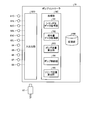
図4は、本実施形態に係るポンプコントローラ19の一例を示す機能ブロック図である。ポンプコントローラ19は、処理部19Cと、記憶部19Mと、入出力部19IOとを有する。処理部19Cはプロセッサであり、記憶部19Mは記憶装置であり、入出力部19IOは入出力インターフェース装置である。記憶部19Mは、処理部19Cが処理を実行する際の一時記憶部としても使用される。
Qa=Qda×√{(PP-LAa)/ΔPL}・・・(3)
Qb=Qdb×√{(PP-LAb)/ΔPL}・・・(4)
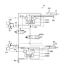
次に、本実施形態に係る油圧ショベル100の制御方法について説明する。図5は、本実施形態に係る油圧ショベル100の制御方法の一例を示すフローチャートである。なお、以下の説明においては、説明を簡単にするために、図6に示すような油圧回路40を制御対象として説明する。図6は、図3を参照して説明した油圧回路40の要部を示す図であって、第1油圧シリンダ群がアームシリンダ22のみを含み、第2油圧シリンダ群がブームシリンダ23のみを含む例を示す。
第2実施形態について説明する。以下の説明において、上述の実施形態と同一又は同等の構成要素については同一の符号を付し、その説明を簡略又は省略する。
Claims (8)
- 作業機及び前記作業機を駆動する複数の油圧シリンダを備える作業機械を制御する制御システムであって、
前記油圧シリンダに供給される作動油を吐出する第1油圧ポンプ及び第2油圧ポンプと、
前記第1油圧ポンプと前記第2油圧ポンプとを接続する通路と、
前記通路に設けられ前記通路を開閉する開閉装置と、
前記油圧シリンダを駆動するために操作される操作装置と、
前記油圧シリンダの前記作動油の圧力を示すシリンダ圧データを取得するシリンダ圧データ取得部と、
前記操作装置の操作量データを取得する操作量データ取得部と、
前記シリンダ圧データと前記操作量データとに基づいて、前記通路が閉じられている分離状態において前記第1油圧ポンプから吐出される前記作動油の流量を示す第1ポンプ流量及び前記第2油圧ポンプから吐出される前記作動油の流量を示す第2ポンプ流量を算出するポンプ流量算出部と、
前記第1ポンプ流量及び前記第2ポンプ流量に基づいて、前記第1油圧ポンプ及び前記第2油圧ポンプを制御するポンプ制御部と、
を備える制御システム。 - 前記分離状態において、前記第1油圧ポンプは、少なくとも1つの前記油圧シリンダを含む第1油圧シリンダ群に供給される前記作動油を吐出し、
前記分離状態において、前記第2油圧ポンプは、少なくとも1つの前記油圧シリンダを含む第2油圧シリンダ群に供給される前記作動油を吐出し、
前記第1ポンプ流量は、前記操作量に基づいて駆動されるために前記第1油圧シリンダ群が必要な前記作動油の流量に基づいて決定され、
前記第2ポンプ流量は、前記操作量に基づいて駆動されるために前記第2油圧シリンダ群が必要な前記作動油の流量に基づいて決定される、
請求項1に記載の制御システム。 - 前記作業機は、バケットと、前記バケットに連結されるアームと、前記アームに連結されるブームとを有し、
前記油圧シリンダは、前記バケットを駆動するバケットシリンダと、前記アームを駆動するアームシリンダと、及び前記ブームを駆動するブームシリンダとを含み、
前記第1油圧シリンダ群は、前記バケットシリンダ及び前記アームシリンダを含み、前記第2アクチュエータ群は、前記ブームシリンダを含む、
請求項2に記載の制御システム。 - 前記作動油の圧力上昇を防止するリリーフ弁と、
前記第1油圧ポンプ及び前記第2油圧ポンプが吐出可能な前記作動油の流量を示すポンプ制限流量と、複数の前記油圧アクチュエータに配分される前記作動油の配分流量の総和とに基づいて、前記リリーフ弁を介して排出される前記作動油の流量を示すリリーフ流量を算出するリリーフ流量算出部と、を備え、
前記ポンプ制御部は、前記リリーフ流量に基づいて、前記第1油圧ポンプ及び前記第2油圧ポンプを制御する、
請求項1から請求項3のいずれか一項に記載の制御システム。 - 前記操作装置が操作されることにより発生するパイロット油圧に基づいて、前記油圧シリンダに供給される前記作動油の流量を調整する主操作弁と、
前記パイロット油圧を検出する操作量検出部と、を備え、
前記操作量データは、前記操作量検出部の検出信号に基づいて算出される、
請求項1から請求項4のいずれか一項に記載の制御システム。 - 前記ポンプ制御部は、前記通路が開けられている合流状態から前記分離状態に遷移するときに、前記ポンプ流量算出部で算出された前記第1ポンプ流量及び前記第2ポンプ流量に基づいて、前記第1油圧ポンプ及び前記第2油圧ポンプを制御する、
請求項1から請求項5のいずれか一項に記載の制御システム。 - 請求項1から請求項6のいずれか一項に記載の制御システムを備える作業機械。
- 作業機及び前記作業機を駆動する複数の油圧シリンダを備える作業機械を制御する制御方法であって、
前記油圧シリンダに供給される作動油を第1油圧ポンプ及び第2油圧ポンプから吐出することと、
前記油圧シリンダの前記作動油の圧力を示すシリンダ圧データを取得することと、
前記油圧シリンダを駆動するために操作される操作装置の操作量データを取得することと、
前記シリンダ圧データと前記操作量データとに基づいて、前記第1油圧ポンプと前記第2油圧ポンプとを接続する通路が開閉装置で閉じられている分離状態において前記第1油圧ポンプから吐出される前記作動油の流量を示す第1ポンプ流量及び前記第2油圧ポンプから吐出される前記作動油の流量を示す第2ポンプ流量を算出することと、
前記第1ポンプ流量及び前記第2ポンプ流量に基づいて、前記第1油圧ポンプ及び前記第2油圧ポンプを制御することと、
を含む制御方法。
Priority Applications (6)
| Application Number | Priority Date | Filing Date | Title |
|---|---|---|---|
| DE112016000103.7T DE112016000103B4 (de) | 2016-07-29 | 2016-07-29 | Steuersystem, Arbeitsmaschine und Steuerverfahren |
| CN201680001246.8A CN106661871B (zh) | 2016-07-29 | 2016-07-29 | 控制系统、作业机械及控制方法 |
| JP2016553668A JP6087034B1 (ja) | 2016-07-29 | 2016-07-29 | 制御システム、作業機械、及び制御方法 |
| PCT/JP2016/072448 WO2017014324A1 (ja) | 2016-07-29 | 2016-07-29 | 制御システム、作業機械、及び制御方法 |
| US15/506,799 US10385545B2 (en) | 2016-07-29 | 2016-07-29 | Control system, work machine, and control method |
| KR1020177004285A KR101972426B1 (ko) | 2016-07-29 | 2016-07-29 | 제어 시스템, 작업 기계, 및 제어 방법 |
Applications Claiming Priority (1)
| Application Number | Priority Date | Filing Date | Title |
|---|---|---|---|
| PCT/JP2016/072448 WO2017014324A1 (ja) | 2016-07-29 | 2016-07-29 | 制御システム、作業機械、及び制御方法 |
Publications (1)
| Publication Number | Publication Date |
|---|---|
| WO2017014324A1 true WO2017014324A1 (ja) | 2017-01-26 |
Family
ID=57834850
Family Applications (1)
| Application Number | Title | Priority Date | Filing Date |
|---|---|---|---|
| PCT/JP2016/072448 Ceased WO2017014324A1 (ja) | 2016-07-29 | 2016-07-29 | 制御システム、作業機械、及び制御方法 |
Country Status (6)
| Country | Link |
|---|---|
| US (1) | US10385545B2 (ja) |
| JP (1) | JP6087034B1 (ja) |
| KR (1) | KR101972426B1 (ja) |
| CN (1) | CN106661871B (ja) |
| DE (1) | DE112016000103B4 (ja) |
| WO (1) | WO2017014324A1 (ja) |
Cited By (3)
| Publication number | Priority date | Publication date | Assignee | Title |
|---|---|---|---|---|
| CN107660257A (zh) * | 2017-07-27 | 2018-02-02 | 株式会社小松制作所 | 控制系统、作业机械、以及控制方法 |
| WO2018180512A1 (ja) * | 2017-03-31 | 2018-10-04 | 日立建機株式会社 | 建設機械 |
| CN111125924A (zh) * | 2019-12-30 | 2020-05-08 | 四川函钛科技有限公司 | 基于qar参数特征提取的飞机着陆自动减速档位识别方法 |
Families Citing this family (7)
| Publication number | Priority date | Publication date | Assignee | Title |
|---|---|---|---|---|
| JP6575916B2 (ja) * | 2016-08-17 | 2019-09-18 | 日立建機株式会社 | 作業車両 |
| JP7061504B2 (ja) | 2018-04-16 | 2022-04-28 | 株式会社小松製作所 | 作動油の監視システム及び作動油の監視方法 |
| JP7253478B2 (ja) * | 2019-09-25 | 2023-04-06 | 日立建機株式会社 | 作業機械 |
| JP7246297B2 (ja) * | 2019-12-16 | 2023-03-27 | 日立建機株式会社 | 建設機械 |
| US11001989B1 (en) * | 2020-03-30 | 2021-05-11 | Caterpillar Inc. | Electrical control of a hydraulic system |
| CN117287383A (zh) * | 2023-09-28 | 2023-12-26 | 徐州徐工挖掘机械有限公司 | 一种正流量主泵标定系统 |
| US12534872B2 (en) | 2024-04-09 | 2026-01-27 | Western States Equipment Company | Hydraulic drive system |
Citations (1)
| Publication number | Priority date | Publication date | Assignee | Title |
|---|---|---|---|---|
| JP2014126126A (ja) * | 2012-12-26 | 2014-07-07 | Kobelco Contstruction Machinery Ltd | 油圧制御装置及びこれを備えた建設機械 |
Family Cites Families (13)
| Publication number | Priority date | Publication date | Assignee | Title |
|---|---|---|---|---|
| JPH03260401A (ja) | 1990-03-09 | 1991-11-20 | Hitachi Constr Mach Co Ltd | 土木・建設機械の油圧駆動装置 |
| US5063739A (en) * | 1991-02-19 | 1991-11-12 | Caterpillar Inc. | Load sensing hydraulic control system |
| JP3596967B2 (ja) * | 1996-02-02 | 2004-12-02 | 日立建機株式会社 | 建設機械の油圧駆動装置 |
| JP2005098455A (ja) | 2003-09-26 | 2005-04-14 | Mitsubishi Heavy Ind Ltd | 産業機械の油圧制御装置 |
| JP4272207B2 (ja) * | 2003-11-14 | 2009-06-03 | 株式会社小松製作所 | 建設機械の油圧制御装置 |
| JP4541209B2 (ja) | 2005-03-31 | 2010-09-08 | ナブテスコ株式会社 | 油圧回路 |
| CN101743362A (zh) * | 2007-06-29 | 2010-06-16 | 维米尔制造公司 | 具有热冲击保护的液压系统 |
| DE102008011016B4 (de) | 2008-02-25 | 2019-02-14 | Linde Hydraulics Gmbh & Co. Kg | Hydrostatisches Antriebssystem |
| US20110056192A1 (en) | 2009-09-10 | 2011-03-10 | Robert Weber | Technique for controlling pumps in a hydraulic system |
| JP5928065B2 (ja) * | 2012-03-27 | 2016-06-01 | コベルコ建機株式会社 | 制御装置及びこれを備えた建設機械 |
| JP5985276B2 (ja) * | 2012-07-02 | 2016-09-06 | 住友建機株式会社 | 建設機械の油圧回路及びその制御装置 |
| JP2014190514A (ja) * | 2013-03-28 | 2014-10-06 | Hitachi Constr Mach Co Ltd | 建設機械のポンプ制御装置 |
| CN203977477U (zh) * | 2014-08-05 | 2014-12-03 | 山河智能装备股份有限公司 | 一种具有针对不同工况切换液压回路的挖掘机 |
-
2016
- 2016-07-29 WO PCT/JP2016/072448 patent/WO2017014324A1/ja not_active Ceased
- 2016-07-29 JP JP2016553668A patent/JP6087034B1/ja active Active
- 2016-07-29 DE DE112016000103.7T patent/DE112016000103B4/de not_active Expired - Fee Related
- 2016-07-29 US US15/506,799 patent/US10385545B2/en active Active
- 2016-07-29 KR KR1020177004285A patent/KR101972426B1/ko active Active
- 2016-07-29 CN CN201680001246.8A patent/CN106661871B/zh active Active
Patent Citations (1)
| Publication number | Priority date | Publication date | Assignee | Title |
|---|---|---|---|---|
| JP2014126126A (ja) * | 2012-12-26 | 2014-07-07 | Kobelco Contstruction Machinery Ltd | 油圧制御装置及びこれを備えた建設機械 |
Cited By (12)
| Publication number | Priority date | Publication date | Assignee | Title |
|---|---|---|---|---|
| WO2018180512A1 (ja) * | 2017-03-31 | 2018-10-04 | 日立建機株式会社 | 建設機械 |
| JP2018172860A (ja) * | 2017-03-31 | 2018-11-08 | 日立建機株式会社 | 建設機械の油圧制御装置 |
| KR20190022780A (ko) * | 2017-03-31 | 2019-03-06 | 히다찌 겐끼 가부시키가이샤 | 건설 기계 |
| CN109563851A (zh) * | 2017-03-31 | 2019-04-02 | 日立建机株式会社 | 工程机械 |
| KR102137127B1 (ko) * | 2017-03-31 | 2020-07-24 | 히다찌 겐끼 가부시키가이샤 | 건설 기계 |
| CN109563851B (zh) * | 2017-03-31 | 2020-07-31 | 日立建机株式会社 | 工程机械 |
| US11098462B2 (en) | 2017-03-31 | 2021-08-24 | Hitachi Construction Machinery Co., Ltd. | Construction machine |
| CN107660257A (zh) * | 2017-07-27 | 2018-02-02 | 株式会社小松制作所 | 控制系统、作业机械、以及控制方法 |
| CN107660257B (zh) * | 2017-07-27 | 2020-06-16 | 株式会社小松制作所 | 控制系统、作业机械、以及控制方法 |
| US11047112B2 (en) | 2017-07-27 | 2021-06-29 | Komatsu Ltd. | Control system, work machine, and control method |
| CN111125924A (zh) * | 2019-12-30 | 2020-05-08 | 四川函钛科技有限公司 | 基于qar参数特征提取的飞机着陆自动减速档位识别方法 |
| CN111125924B (zh) * | 2019-12-30 | 2023-04-11 | 四川函钛科技有限公司 | 基于qar参数特征提取的飞机着陆自动减速档位识别方法 |
Also Published As
| Publication number | Publication date |
|---|---|
| DE112016000103B4 (de) | 2019-08-14 |
| CN106661871A (zh) | 2017-05-10 |
| KR101972426B1 (ko) | 2019-04-25 |
| US20180030692A1 (en) | 2018-02-01 |
| KR20180013839A (ko) | 2018-02-07 |
| JP6087034B1 (ja) | 2017-03-01 |
| US10385545B2 (en) | 2019-08-20 |
| JPWO2017014324A1 (ja) | 2017-07-20 |
| DE112016000103T5 (de) | 2017-05-24 |
| CN106661871B (zh) | 2021-06-18 |
Similar Documents
| Publication | Publication Date | Title |
|---|---|---|
| JP6087034B1 (ja) | 制御システム、作業機械、及び制御方法 | |
| JP6145229B1 (ja) | 制御システム、作業機械、及び制御方法 | |
| KR101834589B1 (ko) | 선회체를 갖는 건설 기계 | |
| JP6244475B1 (ja) | 制御システム、作業機械及び制御方法 | |
| US9702379B2 (en) | Hybrid working machine | |
| US20180305899A1 (en) | Control system and work machine | |
| CN104105888A (zh) | 工程机械 | |
| WO2019064555A1 (ja) | 作業機械の油圧駆動装置 | |
| JP6023391B2 (ja) | 建設機械の駆動装置 | |
| JP6360189B1 (ja) | 制御システム、作業機械、及び制御方法 | |
| JP5872170B2 (ja) | 建設機械の制御装置 | |
| JP6612384B2 (ja) | 制御システム、作業機械、及び制御方法 | |
| JP5642620B2 (ja) | 作業機械のエネルギ回生装置 |
Legal Events
| Date | Code | Title | Description |
|---|---|---|---|
| ENP | Entry into the national phase |
Ref document number: 2016553668 Country of ref document: JP Kind code of ref document: A |
|
| ENP | Entry into the national phase |
Ref document number: 20177004285 Country of ref document: KR Kind code of ref document: A |
|
| 121 | Ep: the epo has been informed by wipo that ep was designated in this application |
Ref document number: 16827882 Country of ref document: EP Kind code of ref document: A1 |
|
| WWE | Wipo information: entry into national phase |
Ref document number: 112016000103 Country of ref document: DE |
|
| 122 | Ep: pct application non-entry in european phase |
Ref document number: 16827882 Country of ref document: EP Kind code of ref document: A1 |