WO2017014206A1 - 操作機構 - Google Patents
操作機構 Download PDFInfo
- Publication number
- WO2017014206A1 WO2017014206A1 PCT/JP2016/071096 JP2016071096W WO2017014206A1 WO 2017014206 A1 WO2017014206 A1 WO 2017014206A1 JP 2016071096 W JP2016071096 W JP 2016071096W WO 2017014206 A1 WO2017014206 A1 WO 2017014206A1
- Authority
- WO
- WIPO (PCT)
- Prior art keywords
- contact
- rod member
- mounting member
- guide pipe
- contact portion
- Prior art date
- Legal status (The legal status is an assumption and is not a legal conclusion. Google has not performed a legal analysis and makes no representation as to the accuracy of the status listed.)
- Ceased
Links
Images

Classifications
-
- F—MECHANICAL ENGINEERING; LIGHTING; HEATING; WEAPONS; BLASTING
- F16—ENGINEERING ELEMENTS AND UNITS; GENERAL MEASURES FOR PRODUCING AND MAINTAINING EFFECTIVE FUNCTIONING OF MACHINES OR INSTALLATIONS; THERMAL INSULATION IN GENERAL
- F16C—SHAFTS; FLEXIBLE SHAFTS; ELEMENTS OR CRANKSHAFT MECHANISMS; ROTARY BODIES OTHER THAN GEARING ELEMENTS; BEARINGS
- F16C1/00—Flexible shafts; Mechanical means for transmitting movement in a flexible sheathing
- F16C1/10—Means for transmitting linear movement in a flexible sheathing, e.g. "Bowden-mechanisms"
- F16C1/12—Arrangements for transmitting movement to or from the flexible member
- F16C1/16—Arrangements for transmitting movement to or from the flexible member in which the end-piece is guided rectilinearly
-
- F—MECHANICAL ENGINEERING; LIGHTING; HEATING; WEAPONS; BLASTING
- F16—ENGINEERING ELEMENTS AND UNITS; GENERAL MEASURES FOR PRODUCING AND MAINTAINING EFFECTIVE FUNCTIONING OF MACHINES OR INSTALLATIONS; THERMAL INSULATION IN GENERAL
- F16G—BELTS, CABLES, OR ROPES, PREDOMINANTLY USED FOR DRIVING PURPOSES; CHAINS; FITTINGS PREDOMINANTLY USED THEREFOR
- F16G11/00—Means for fastening cables or ropes to one another or to other objects; Caps or sleeves for fixing on cables or ropes
- F16G11/04—Means for fastening cables or ropes to one another or to other objects; Caps or sleeves for fixing on cables or ropes with wedging action, e.g. friction clamps
Definitions
- the present invention relates to an operation mechanism that connects an operation member and an operated member.
- a control cable is used to connect the operation unit and the operated unit.
- a control cable that connects a shift lever and a transmission is used to operate a shift lever (operating unit) and switch a transmission (operated unit) (for example, Patent Document 1).
- a sliding resistance may be set in a predetermined range.
- the sliding resistance between the cap provided at the end of the guide pipe and the rod slidingly moving in the inner space of the guide pipe affects the operational feeling. Is set within a predetermined range.
- the contact state between the members needs to be in a predetermined state. Since it is necessary to manage so that the dimension and elasticity of a member may become a predetermined range, manufacture is difficult. Even if the sliding resistance of the operating mechanism is adjusted at the initial stage, if the contact state between the members or the elasticity of the members has changed due to use over time, it is necessary to adjust the sliding resistance appropriately. In some cases, it is necessary to perform an exchange operation for selecting and exchanging the members.
- an object of the present invention is to provide an operation mechanism that can easily obtain a predetermined sliding resistance.
- An operation mechanism is attached to a tubular member, a rod member that slides in an inner space of the tubular member, a cable having one end connected to the rod member, and the tubular member.
- a mounting member movable in the axial direction of the cylindrical member, and an operating mechanism for connecting the operating member and the operated member via the cable and the rod member, wherein the cylindrical member is
- the contact member is movable in the proximity direction with respect to the rod member, has a contact portion that can contact the rod member, and the mounting member includes a pressing portion that contacts the rod member by pressing the contact portion.
- the contact state between the contact portion and the rod member is changed by the pressing of the pressing portion to the contact portion according to the movement of the mounting member in the axial direction of the cylindrical member, and the sliding resistance is changed. It can be adjusted.
- the operation mechanism according to one embodiment of the present invention can easily obtain a desired sliding resistance.
- (A) is the figure which showed the operation mechanism which concerns on 1st embodiment of this invention
- (b) is the sectional view on the AA line in Fig.1 (a).
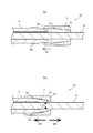
- (A) And (b) is sectional drawing of the front-end
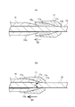
- (A) And (b) is sectional drawing of the front-end
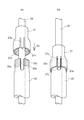
- (A) And (b) is a figure of the front-end
- a control cable 10 that is an operation mechanism according to the first embodiment of the present invention will be described with reference to FIGS. 1 and 2.
- the control cable 10 connects a shift lever L that is an operating member and a transmission M that is an operated member. As a result, the user can operate the transmission M via the shift lever L and the control cable 10.
- the control cable 10 includes an inner cable 3 that is an embodiment of a cable included in the operation mechanism according to the present invention, an outer casing 4 that covers the periphery of the inner cable 3, and a cylindrical shape that accommodates both ends of the inner cable 3 therein.
- Guide pipes 5 and 5 that are members, rod members 6 and 6 that are connected to both ends of the inner cable 3 inside the guide pipe 5 and extend from the guide pipes 5 and 5, and the rod member 6 in the guide pipe 5 includes And cylindrical mounting members 7 and 7 mounted on the outside of the end portion on the extending side.
- the guide pipe 5, the rod member 6, and the mounting member 7 are arranged at both ends of the control cable 10, but each is arranged only at one end of the control cable 10. It is also possible to do.
- the guide pipe 5 and the mounting member 7 according to the present embodiment are each formed of a synthetic resin, but may be formed of other materials such as metal or carbon fiber.
- the rod member 6 is typically formed of a metal such as stainless steel, but may be formed of another hard material such as synthetic resin or carbon fiber.
- the inner cable 3 is a rope-like long body obtained by twisting metal wires and synthetic resin wires.
- the outer casing 4 includes a synthetic resin tube-shaped liner, a reinforcing layer in which a metal wire is spirally wound around the outer periphery of the liner, and a synthetic resin coating layer provided on the outer surface of the reinforcing layer. And have. Of course, it is not necessary to provide a liner or a reinforcing layer, and the reinforcing layer may have other configurations.
- the inner cable 3 is accommodated in the outer casing 4 so as to be slidable in the axial direction.
- the guide pipes 5 and 5 are one embodiment of a cylindrical member provided in the operation mechanism according to the present invention, and are respectively connected to the end of the outer casing 4.
- a substantially spherical head 5 a is formed at one end of the guide pipe 5.
- the outer cap 8 is a hollow member from which the end portion of the outer casing 4 is inserted and fixed, and leads out the inner cable 3, and a large-diameter portion 8a having a larger outer diameter than other portions is formed.
- the guide pipe 5 is supported so as to be slidable with respect to the connection member 12 by accommodating the head portion 5a of the guide pipe 5 in the head accommodation portion 12a formed inside the connection member 12.
- the outer casing 4 is fixed to the connecting member 12 by accommodating the large diameter portion 8 a of the outer cap 8 in the large diameter portion accommodating portion 12 b formed inside the connecting member 12. Thereby, the one end parts of the guide pipes 5 and 5 are connected to the both end parts of the outer casing 4 via the connecting members 12 and 12. Further, the connecting members 12 and 12 are fixed to the brackets 11 and 11, so that both end portions of the outer casing 4 are supported.
- each of the protrusions of the engaging stepped portion 5b includes a surface orthogonal to the axis of the guide pipe 5 and an upper portion of this surface (the outer peripheral side of the guide pipe 5) and the other end side of the guide pipe 5. And a surface inclined toward the central axis. As shown in FIGS.
- the contact portion 5 c is formed so as to be movable inward in the radial direction that is the proximity direction to the rod member 6.
- Each convex part of the engagement step part 5b should just be formed so that it can engage with each of the recessed part provided in the to-be-engaged step part 7a of the mounting member 7 mentioned later, for example, it is the same shape. They may be formed continuously at the same interval in the axial direction, or may be formed in a spiral shape.
- the rod member 6 can be connected to the end of the inner cable 3 such that the end of the inner cable 3 is fixed by a method such as caulking or bonding, and can slide in the inner space of the guide pipe 5. It is the made rod-shaped member. The other end of the rod member 6 extends from the other end of the guide pipe 5.
- the rod member 6 connected to the shift lever L is configured as an operation unit side rod member 6i
- the rod member 6 connected to the transmission M is configured as an operated unit side rod member 6o.
- the operating portion side rod member 6i has an insertion hole 6a at the tip.
- the mounting member 7 is a member formed in a short cylinder shape, and is mounted on the outer side of the other end side of the guide pipe 5. Specifically, the inner circumferential surface of the mounting member 7 has a saw-like cross section passing through the shaft center, and an engaged stepped portion 7a that can be engaged with the engaging stepped portion 5b is formed. More specifically, similarly to the engaging stepped portion 5b, the engaged stepped portion 7a is provided with a plurality of recesses, each of which has a surface orthogonal to the axis of the mounting member 7, and The lower surface (the outer peripheral side of the mounting member 7) is formed by a surface that is inclined toward the other end side of the mounting member 7 and toward the central axis.
- the mounting member 7 is moved as indicated by an arrow S1 in FIG. 2A, and the engaged stepped portion 7a and the engaging stepped portion 5b of the guide pipe 5 are engaged (here, they are engaged).
- the mounting member 7 is mounted on the other end side of the guide pipe 5 as shown in FIG. Since the concave portion of the engaged stepped portion 7a can be engaged with the respective convex portions of the engaging stepped portion 5b, the convex portion of the engaging stepped seat portion 5b and the engaged stepped portion 7a By adjusting the engagement position, the relative position of the mounting member 7 with respect to the guide pipe 5 can be adjusted.
- the mounting member 7 is configured to be movable in the axial direction in the guide pipe 5 by adjusting the relative position between the engaged stepped portion 7a and the engaged stepped portion 5b. That is, by adjusting the amount of engagement between the engaged stepped portion 7a and the engaging stepped portion 5b of the guide pipe 5, the pressing force of the contact portion 5c on the rod member 6 and the rod member 6 of the contact portion 5c are adjusted. Can be adjusted (details will be described later).
- the mounting member 7 is formed in a short cylinder shape having openings at both end portions, and both the opening portions communicate with each other through a hollow portion.
- the mounting member 7 is further inserted until the tip of the guide pipe 5 is inserted from one opening until the engaging stepped portion 5b reaches the engaged stepped portion 7a formed on the inner wall of the hollow portion.
- the inner wall of the hollow portion in the vicinity of the other opening (the opening opposite to the side where the tip of the guide pipe 5 is inserted) has a tapered portion that is reduced in diameter so that the inner diameter gradually decreases toward the other opening. And the tip of the guide pipe 5 comes into contact with the tapered portion. Both openings have an inner diameter larger than the outer diameter of the guide pipe 5.
- the tip of the guide pipe 5 and the tapered portion are adjusted.
- the contact position is adjusted, and the degree of curvature in the inner direction of the tip of the guide pipe 5 is adjusted.
- the mounting member 7 is formed with a pressing portion 7 c that presses the contact portion 5 c when the mounting member 7 is mounted on the guide pipe 5 to bring the contact portion 5 c into contact with the outer peripheral surface of the rod member 6.
- the distance (clearance) between the pressing portion 7c and the outer peripheral surface of the rod member 6 is formed to be smaller than the radial thickness (thickness) of the contact portion 5c (see FIG. 2A).
- the contact part 5c is formed so that it may reduce in diameter from the one end side of the rod member 5 toward the other end side.
- the engaged stepped portion 7a extends from one end side (the left side in FIGS. 2 (a) and 2 (b)) to the other end side (FIG. 2 (a)). And it is formed in the taper shape diameter-reduced toward the right side in (b). For this reason, as shown by an arrow M1 in FIG. 2B, the amount of engagement between the engaged stepped portion 7a and the engaged stepped portion 5b is adjusted, and the mounting member 7 is moved to one end side of the guide pipe 5. When moved, the contact portion 5 c enters between the pressing portion 7 c of the mounting member 7 and the rod member 6.
- the outer peripheral surface of the contact portion 5c is pressed radially inward from the inner peripheral surface of the pressing portion 7c, and the contact portion 5c moves in the direction of reducing the diameter (radially inner side). Since the distance between the pressing portion 7c and the outer peripheral surface of the rod member 6 is smaller than the radial thickness of the contact portion 5c, when the contact portion 5c is pressed by the pressing portion 7c, the inner peripheral surface of the contact portion 5c is a rod. It moves in the direction of the outer peripheral surface of the member 6 and adheres.
- the contact portion 5c is formed so as to be gradually reduced in diameter from the operated portion side toward the operation portion side, so that the distal end side (operation portion side) of the contact portion 5c is the rod member. 6 will be in close contact.
- the contact portion 5c When the amount of engagement between the engaged stepped portion 7a and the engaged stepped portion 5b is small (when the moving amount of the mounting member 7 to the arrow M1 side is small), the contact portion 5c is pressed from the pressing portion 7c. Since the area is small, the contact area of the contact portion 5c with the rod member 6 is relatively small. On the other hand, when the mounting member 7 is moved further to the arrow M1 side to increase the amount of engagement between the engaged stepped portion 7a and the engaged stepped portion 5b, the contact portion 5c is pressed from the pressing portion 7c. Since the area increases, the contact area of the contact portion 5c with the rod member 6 becomes relatively large.
- the contact portion 5c is formed so as to be gradually reduced in diameter from the operated portion side toward the operation portion side. Side) gradually increases, and as a result, the pressing force to the rod member 6 increases. In other words, it can be said that the pressing force for pressing the rod member is larger on the operation portion side of the contact portion 5c. In this way, by adjusting the amount of engagement between the engaged stepped portion 7a and the engaging stepped portion 5b of the guide pipe 5, the pressing force of the contact portion 5c to the rod member 6 and the rod member of the contact portion 5c are adjusted. The contact area to 6 can be adjusted.
- the contact portion 5c comes into contact with the outer peripheral surface of the rod member 6, and the contact portion 5c is pressed against the rod member 6 as shown by an arrow F1 in FIG. Thereby, when the rod member 6 slides inside the guide pipe 5, a sliding resistance is generated between the contact portion 5 c and the rod member 6.
- the contact portion 5c is moved by moving the mounting member 7 in the axial direction of the guide pipe 5 by adjusting the amount of engagement between the engaged stepped portion 7a and the engaged stepped portion 5b. It is configured to move inward in the radial direction.
- the contact state of the contact part 5c and the rod member 6 can be changed by the pressing to the contact part 5c of the press part 7c according to the movement to the axial direction of the guide pipe 5 of the mounting member 7.
- FIG. the sliding resistance generated between the contact portion 5c and the rod member 6 can be adjusted by adjusting the amount of engagement between the engaged stepped portion 7a and the engaging stepped portion 5b.
- a method for moving the mounting member 7 in the axial direction of the guide pipe 5 by adjusting the meshing amount will be described.
- the mounting member 7 can be pushed in the direction of the non-operation portion with respect to the guide pipe 5 to be moved in the M1 direction in FIG.
- the engaging stepped portion 5b and the engaged stepped portion 7 are formed so that the surface formed on the contact portion 5c side is formed obliquely with respect to the axial direction of the mounting member 7.
- the engagement step portion 5b can be overcome, and the mounting member 7 can be easily moved in the M1 direction.
- the movement in the reverse direction (M2 direction in FIG. 2B) is restricted. Is done.
- the mounting member 7 is moved toward the operation portion with respect to the guide pipe 5 (moved in the direction M2 in FIG. 2B). At this time, as described above, movement in the M2 direction is restricted. Therefore, in order to move the mounting member 7 in the M2 direction, the engagement (engagement) between the engaged stepped portion 7a and the engaging stepped portion 5b is released by expanding the mounting member diameter, and the like. The member 7 is moved in the M2 direction.
- the sliding resistance generated between the guide pipe 5 and the rod member 6 can be easily adjusted by configuring as described above. That is, if the sliding resistance generated between the guide pipe 5 and the rod member 6 is weak, the amount of engagement between the engaged stepped portion 7a and the engaging stepped portion 5b is adjusted, and the mounting member 7 is moved to the guide pipe 5 Move to one end side. As a result, the pressing force of the contact portion 5c on the rod member 6 increases, and the contact area of the contact portion 5c with the rod member 6 increases, so that the sliding between the guide pipe 5 and the rod member 6 occurs. Dynamic resistance can be increased.
- the sliding resistance generated between the guide pipe 5 and the rod member 6 can be adjusted only by adjusting the position of the mounting member 7 in the guide pipe 5, so that the dimensions and elasticity of each member are predetermined. Therefore, manufacturing is easy. Further, even when the contact state between the guide pipe 5 and the rod member 6 or the elasticity of each member changes due to the use over time, the sliding resistance can be adjusted without replacing the member.
- control cable that is an operation mechanism according to the second embodiment of the present invention will be described with reference to FIG. Since the control cable described in the following embodiments and the like are substantially the same in configuration as the control cable 10 according to the first embodiment, the control cable will be described focusing on a configuration different from the control cable 10 according to the first embodiment. .
- the guide pipe 15 in this embodiment is a cylindrical member connected to both ends of an outer casing (not shown), as in the first embodiment.
- One end of the guide pipe 15 is connected to the end of the outer casing via a connecting member (not shown).
- a contact portion 15 c that can contact the rod member 6 is formed.
- the external thread part 15b is formed in the outer peripheral surface of the part adjacent to the contact part 15c.
- the contact portion 15 c is formed so as to be movable inward in the radial direction, which is the proximity direction to the rod member 16.
- the contact portion 15c is formed as a thin portion that can be bent and is thin.
- the mounting member 17 is a member formed in a short cylinder shape, and is mounted on the outer side of the other end side of the guide pipe 15. Specifically, a female threaded portion 17a is formed on the inner peripheral surface of the mounting member 17, and the female threaded portion 17a and the male threaded portion 15b of the guide pipe 15 are screwed together as indicated by an arrow S2 in FIG. Thus, the mounting member 17 is mounted on the other end side of the guide pipe 15.
- the mounting member 17 is configured to be movable in the axial direction in the guide pipe 15 by adjusting the amount of screwing between the female screw portion 17a and the male screw portion 15b.
- the sliding contact portion 17 b formed at the end portion of the mounting member 17 is configured to be in sliding contact with the outer peripheral surface of the rod member 16.
- the contact portion 15 c is pressed against the rod member 16 by pressing the contact portion 15 c when the mounting member 17 is mounted on the guide pipe 15.
- a pressing portion 17c that is brought into contact with the outer peripheral surface is formed.
- the pressing portion 17c is a reduced diameter portion in which the inner diameter of the mounting member 17 is reduced. And it is set as the structure which the press position to the contact part 15c of the press part 17c moves by the movement of the mounting member 17 (the area
- the female screw portion 17a and the male screw portion 15b are tapered so that the diameter thereof decreases toward the other end side of the guide pipe 15 (the right side in FIGS. 3A and 3B). Is formed. For this reason, as shown by an arrow M2 shown in FIG. 3B, the amount of screwing between the female screw portion 17a and the male screw portion 15b is adjusted, and the mounting member 17 is connected to one end side of the guide pipe 15 (FIG. 3A). And when it is moved to the left side in (b), the contact portion 15 c enters between the pressing portion 17 c of the mounting member 17 and the rod member 6.
- the outer peripheral surface of the contact portion 15c is pressed radially inward from the inner peripheral surface of the pressing portion 17c, and the contact portion 15c moves in the direction of reducing the diameter (radially inner side). Since the pressing portion 17c is formed as a reduced diameter portion in which the inner diameter of the mounting member 17 is reduced toward the distal end side (opposite side of the guide pipe 15), when the contact portion 15c is pressed by the pressing portion 17c, The inner peripheral surface of the contact portion 15c is in close contact with the outer peripheral surface of the rod member 16, and the pressing area increases. Further, the pressing force increases toward the tip side.
- the contact portion 15c comes into contact with the outer peripheral surface of the rod member 16, and the contact portion 15c is pressed against the rod member 16 as shown by an arrow F2 in FIG. Thereby, when the rod member 16 slides inside the guide pipe 15, a sliding resistance is generated between the contact portion 15 c and the rod member 16. Further, in the present embodiment, the contact portion 15c is moved inward in the radial direction by adjusting the screwing amount of the female screw portion 17a and the male screw portion 15b and moving the mounting member 17 in the axial direction of the guide pipe 15.
- the configuration is to let For this reason, the contact state of the contact part 15c and the rod member 16 can be changed by the pressing to the contact part 15c of the press part 17c according to the movement to the axial direction of the guide pipe 15 of the mounting member 17.
- FIG. the sliding resistance generated between the contact portion 15c and the rod member 16 can be adjusted by adjusting the screwing amount between the female screw portion 17a and the male screw portion 15b.
- the sliding portion generated between the contact portion 15c and the rod member 16 is more easily adjusted by forming the contact portion 15c as a thin-walled portion so as to be easily bent.
- the reduced diameter portion in the pressing portion 17c does not need to be provided continuously in the circumferential direction, and the reduced diameter portion may be formed intermittently in the circumferential direction.
- the outer peripheral surface of the guide pipe 15 is provided with a male screw portion 15b that is a screwed portion to be screwed with the mounting member 17, and the movement of the mounting member 17 in the axial direction of the guide pipe 15 is as follows. This is done by adjusting the screwing amount of the mounting member 17 to the guide pipe 15. Thus, by adjusting the screwing amount of the male screw portion 15b and the female screw portion 17a, it is possible to move the mounting member 17 in the axial direction of the guide pipe 15, and thereby the contact portion 15c and the rod member 16 Can be easily adjusted.
- the guide pipe 25 is a cylindrical member that is connected to an end portion of an outer casing (not shown), as in the first embodiment.
- One end of the guide pipe 25 is connected to the end of the outer casing via a connecting member (not shown).
- a male screw portion 25b is formed on the outer peripheral surface on the other end side of the guide pipe 25.
- a contact portion 25 c that can contact the rod member 26 is formed at the tip of the other end portion of the guide pipe 25.
- the contact portion 25 c is formed so as to be movable inward in the radial direction, which is the proximity direction to the rod member 26.
- the slit 25d is formed in the one end part of the guide pipe 25 which concerns on this embodiment along the axial direction.
- the mounting member 27 is a member formed in a short cylinder shape, and is mounted on the outer side of the other end side of the guide pipe 25. Specifically, a female threaded portion 27a is formed on the inner peripheral surface of the mounting member 27, and the female threaded portion 27a and the male threaded portion 25b of the guide pipe 5 are screwed together as indicated by an arrow S3 in FIG. Thus, the mounting member 27 is mounted on the other end side of the guide pipe 25.
- the mounting member 27 is configured to be movable in the axial direction in the guide pipe 25 by adjusting the screwing amount between the female screw portion 27a and the male screw portion 25b.
- the mounting member 27 is formed with a protrusion 27c that fits into the slit 25d.
- the end of the mounting member 27 on the guide pipe 25 side is formed with two notches along the axial direction, so that it can be elastically deformed in the radial direction.
- a flat leaf spring portion 27b is formed.
- the protrusion part 27c which protrudes to a radial inside is formed in the front-end
- the contact portion 25 c comes into contact with the outer peripheral surface of the rod member 26, and the contact portion 25 c is pressed against the rod member 26. Accordingly, when the rod member 26 slides inside the guide pipe 25, a sliding resistance is generated between the contact portion 25c and the rod member 26.
- the contact portion 25c is moved inward in the radial direction by adjusting the screwing amount of the female screw portion 27a and the male screw portion 25b and moving the mounting member 27 in the axial direction of the guide pipe 25.
- the configuration is to let For this reason, the contact state of the contact part 25c and the rod member 26 can be changed by the pressing to the contact part 25c according to the movement of the guide member 25 in the axial direction of the mounting member 27. That is, the sliding resistance generated between the contact portion 25c and the rod member 26 can be adjusted by adjusting the screwing amount between the female screw portion 27a and the male screw portion 25b.
- the slit 25d is formed in the guide pipe 25, and the protrusion 27c formed on the mounting member 27 is fitted into the slit 25d, so that the threaded engagement between the female screw portion 27a and the male screw portion 25b is loosened.
- the sliding resistance generated between the portion 25c and the rod member 26 is prevented from decreasing, and as a result, the sliding resistance is suppressed so that the operational feeling does not change.
- the slit 25d is formed in the guide pipe 25 and the projection 27c is formed in the mounting member 27.
- the projection is formed in the guide pipe 25 and the slit is formed in the mounting member 27. It is also possible.
- the operation mechanism of the present invention can adopt various forms from the first embodiment to the third embodiment, but is not limited to these embodiments, Among these embodiments, forms such as a guide pipe and a mounting member can be appropriately combined and used according to the purpose and application.
Landscapes
- Engineering & Computer Science (AREA)
- General Engineering & Computer Science (AREA)
- Mechanical Engineering (AREA)
- Health & Medical Sciences (AREA)
- Oral & Maxillofacial Surgery (AREA)
- Flexible Shafts (AREA)
Abstract
本発明は、ケーブル(3)及び該ケーブル(3)に一端が接続されるロッド部材(6)を介して操作部材(L)と被操作部材(M)とを接続する操作機構(10)であって、前記ロッド部材(6)が摺動する内部空間を有する筒状部材(5)は、前記ロッド部材(6)に対して近接方向へ移動可能であり且つ前記ロッド部材(6)に接触可能な接触部(5c)を有し、前記筒状部材(5)に装着され且つ前記筒状部材(5)の軸方向へ移動可能な装着部材(7)は、前記接触部(5c)を押圧することで前記ロッド部材(6)へ接触させる押圧部(7c)を備え、前記装着部材(7)の前記筒状部材(5)の軸方向への移動に応じた前記押圧部(7c)の前記接触部(5c)への押圧により、前記接触部(5c)と前記ロッド部材(6)との接触状態を変化させて、摺動抵抗を調整し得る操作機構に関する。
Description
本発明は、操作部材と被操作部材とを接続する操作機構に関する。
従来、操作部と被操作部とを接続するために、コントロールケーブルが用いられている。例えば、自動車等において、シフトレバー(操作部)を操作してトランスミッション(被操作部)を切換えるために、シフトレバーとトランスミッションとを接続するコントロールケーブルが用いられている(例えば、特許文献1)。コントロールケーブルを用いた操作機構については、使用者の操作感を良好にするために、摺動抵抗が所定の範囲内となるように設定することが求められる。例えば、トランスミッションに用いられる場合においては、ガイドパイプの端部に設けられたキャップとガイドパイプの内側空間を摺動移動するロッドとの摺動抵抗が操作感に影響を与えるため、その摺動抵抗が所定範囲内に設定される。
しかし、キャップやガイドパイプとロッドとの摺動抵抗など、部材間の摺動抵抗を所定の範囲内となるようにするには、部材間の接触状態を所定の状態とする必要があり、各部材の寸法や弾性が所定の範囲となるように管理する必要があるため、製造が難しい。また、操作機構の摺動抵抗が初期の段階で調整されていても、経年の使用により部材間の接触状態や部材の弾性が変化した場合には、摺動抵抗の調整のために、適切な部材を選択して交換する交換作業をしなければならない場合もある。
そこで、本発明の目的は、所定の摺動抵抗を容易に得ることができる操作機構を提供することにある。
本発明の一態様に係る操作機構は、筒状部材と、前記筒状部材の内側空間を摺動するロッド部材と、一端が前記ロッド部材に接続されるケーブルと、前記筒状部材に装着され、前記筒状部材の軸方向へ移動可能な装着部材と、を備え、前記ケーブルおよび前記ロッド部材を介して操作部材と被操作部材とを接続する操作機構であって、前記筒状部材は、前記ロッド部材に対して近接方向へ移動可能であり、前記ロッド部材に接触可能な接触部を有し、前記装着部材は、前記接触部を押圧することで前記ロッド部材へ接触させる押圧部を備え、前記装着部材の前記筒状部材の軸方向への移動に応じた前記押圧部の前記接触部への押圧により、前記接触部と前記ロッド部材との接触状態を変化させて、摺動抵抗を調整し得るものである。
本発明の一態様に係る操作機構は、所望の摺動抵抗を容易に得ることができる。
<第一実施形態>
図1及び図2を用いて、本発明の第一実施形態に係る操作機構であるコントロールケーブル10について説明する。コントロールケーブル10は、操作部材であるシフトレバーLと、被操作部材であるトランスミッションMとを接続する。これにより使用者がシフトレバーL及びコントロールケーブル10を介してトランスミッションMを操作することが可能となる。
図1及び図2を用いて、本発明の第一実施形態に係る操作機構であるコントロールケーブル10について説明する。コントロールケーブル10は、操作部材であるシフトレバーLと、被操作部材であるトランスミッションMとを接続する。これにより使用者がシフトレバーL及びコントロールケーブル10を介してトランスミッションMを操作することが可能となる。
コントロールケーブル10は、本発明に係る操作機構が備えるケーブルの一態様であるインナーケーブル3と、インナーケーブル3の周囲を被覆するアウターケーシング4と、インナーケーブル3の両端部を内部に収容する筒状部材であるガイドパイプ5,5と、ガイドパイプ5の内部でインナーケーブル3の両端部と接続されてガイドパイプ5,5から延出されるロッド部材6,6と、ガイドパイプ5においてロッド部材6が延出される側の端部の外側に装着される筒状の装着部材7,7と、を備える。なお、本実施形態においては、ガイドパイプ5、ロッド部材6、及び、装着部材7をコントロールケーブル10の両端に配設する構成としているが、それぞれをコントロールケーブル10の一端のみに配設する構成とすることも可能である。また、本実施形態に係るガイドパイプ5、及び、装着部材7はそれぞれ合成樹脂で形成されているが、金属や炭素繊維等の他の素材で形成することも可能である。ロッド部材6はステンレススチールなどの金属で形成されることが代表的であるが、合成樹脂等や炭素繊維等の他の硬質な素材で形成されてもよい。
インナーケーブル3は、金属線や合成樹脂線を撚り合わせたロープ状の長尺体である。アウターケーシング4は、ここでは、合成樹脂製のチューブ状のライナーと、金属線をライナーの外周に螺旋状に巻きつけた補強層と、補強層の外表面に設けられた合成樹脂製の被覆層とを有している。もちろん、ライナーや補強層は設けなくてもよく、補強層は他の構成とすることもできる。インナーケーブル3はアウターケーシング4の内部で軸方向に摺動可能に収容されている。
ガイドパイプ5,5は、本発明に係る操作機構が備える筒状部材の一態様であり、アウターケーシング4の端部にそれぞれ連結される。ガイドパイプ5の一端部には略球状の頭部5aが形成される。また、ここでは、アウターケーシング4の端部は、アウターキャップ8に挿通される。アウターキャップ8は、アウターケーシング4の端部が挿入されて固定されると共に、インナーケーブル3を導出する中空の部材であり、他の部分よりも外径の大きな大径部8aが形成される。そして、連結部材12の内部に形成された頭部収容部12aにガイドパイプ5の頭部5aが収容されることにより、ガイドパイプ5が連結部材12に対して搖動可能に支持される。また、連結部材12の内部に形成された大径部収容部12bにアウターキャップ8の大径部8aが収容されることにより、アウターケーシング4が連結部材12に固定される。これにより、ガイドパイプ5,5の一端部が連結部材12,12を介してアウターケーシング4の両端部に連結される。また、連結部材12,12がブラケット11,11に固定されることにより、アウターケーシング4の両端部が支持される。
ガイドパイプ5の他端側の先端付近には、ロッド部材6に接触可能な接触部5cが形成されている。また、接触部5cに隣接した部分の外周面には、軸心を通る断面が鋸刃状(複数の略三角形の凸部が連続した形状)となる係合段差部5bが形成されている。より詳細には、係合段差部5bの凸部のそれぞれは、ガイドパイプ5の軸心と直交する面と、この面の上部(ガイドパイプ5の外周側)からガイドパイプ5の他端側かつ中心軸へ向かって傾斜する面とにより形成される。図2(a)及び(b)に示す如く、接触部5cはロッド部材6に対する近接方向である半径方向内側に移動可能に形成されている。係合段差部5bの各凸部は、後述の、装着部材7の被係合段差部7aに設けられた凹部のそれぞれと係合可能なように形成されていればよく、例えば同一形状であって同一間隔で、軸心方向に連続して形成されてもよく、螺旋状に形成されてもよい。
ロッド部材6は、インナーケーブル3の端部が加締めや接着などの方法により固定されるなど、インナーケーブル3の端部に接続可能であって、ガイドパイプ5の内側空間を摺動可能に構成された棒状部材である。ロッド部材6の他端部はガイドパイプ5の他端部から延出される。本実施形態においては、シフトレバーLと接続されるロッド部材6は操作部側ロッド部材6iとして構成され、トランスミッションMと接続されるロッド部材6は被操作部側ロッド部材6oとして構成されている。操作部側ロッド部材6iには、先端部に挿入孔6aが開口されている。この挿入孔6aにシフトレバーLの端部が挿入されることにより、操作部側ロッド部材6iとシフトレバーLとが連結される。このように、シフトレバーLとトランスミッションMとは、インナーケーブル3及びロッド部材6,6を介して接続される。
装着部材7は短筒状に形成された部材であり、ガイドパイプ5の他端側の外側に装着される。詳細には、装着部材7の内周面には軸心を通る断面が鋸状であり、係合段差部5bと係合可能な被係合段差部7aが形成されている。より詳細には、係合段差部5bと同様に、被係合段差部7aには複数の凹部が設けられ、その凹部のそれぞれは、装着部材7の軸心と直交する面と、この面の下部(装着部材7の外周側)から装着部材7の他端側かつ中心軸へ向かって傾斜する面とにより形成される。そして、装着部材7を図2(a)中の矢印S1に示す如く移動させ、被係合段差部7aとガイドパイプ5の係合段差部5bとを係合させることにより(ここでは、噛み合わせることにより)、図2(b)に示す如く装着部材7がガイドパイプ5の他端側に装着される。被係合段差部7aの凹部が、いずれについても係合段差部5bのそれぞれの凸部と係合可能となっているため、係合段座部5bの凸部と被係合段差部7aとの係合位置を調節することにより、ガイドパイプ5に対する装着部材7の相対位置を調整することができる。
装着部材7は、被係合段差部7aと係合段差部5bとの相対位置を調節することにより、ガイドパイプ5において軸方向に移動できるように構成されている。すなわち、被係合段差部7aとガイドパイプ5の係合段差部5bとの噛み合わせ量を調整することで、接触部5cのロッド部材6への押圧力、および接触部5cのロッド部材6への接触面積を調整することができる(詳細は後述)。本実施形態においては、装着部材7は、両端部に開口を有する短筒状に形成され、両開口部は中空部により連通している。装着部材7は、一方の開口からガイドパイプ5の先端が挿入され、中空部の内壁に形成された被係合段差部7aに係合段差部5bが到達するまで、さらに挿入される。他方の開口(ガイドパイプ5の先端が挿入される側とは反対側の開口)付近の中空部の内壁は、その他方の開口に向かうに従い内径が徐々に小さくなるように縮径するテーパ部を有し、ガイドパイプ5の先端がこのテーパ部と当接するようになっている。両開口部は、ガイドパイプ5の外径よりも大きい内径を有している。係合段差部5bと被係合段差部7aとが係合する位置、すなわち軸方向におけるガイドパイプ5に対する装着部材7の相対位置を調整することにより、ガイドパイプ5の先端と前記テーパ部との当接位置が調整されて、ガイドパイプ5の先端の内側方向への湾曲度合が調整される。この湾曲度合が大きくなるにつれて、ロッド部材6に対するガイドパイプ5の先端の押圧力が大きくなる(詳細については後述する)。装着部材7には、装着部材7をガイドパイプ5に装着した際に接触部5cを押圧することで接触部5cをロッド部材6の外周面へ接触させる押圧部7cが形成されている。押圧部7cとロッド部材6の外周面との間隔(クリアランス)は、接触部5cの半径方向の厚み(肉厚)よりも小さくなるように形成されている(図2(a)を参照)。特に、本実施形態では、接触部5cは、ロッド部材5の一端側から他端側に向かって縮径するように形成されている。
図2(a)及び(b)に示す如く、被係合段差部7aは、ガイドパイプ5の一端側(図2(a)及び(b)における左側)から他端側(図2(a)及び(b)における右側)に向かって縮径するテーパ形状に形成されている。このため、図2(b)中に示す矢印M1に示す如く、被係合段差部7aと係合段差部5bとの係合量を調節して、装着部材7をガイドパイプ5の一端側に移動させた場合、装着部材7の押圧部7cとロッド部材6との間に接触部5cが入り込む。この際、接触部5cの外周面が押圧部7cの内周面から半径方向内側に押圧され、接触部5cが縮径する方向(半径方向内側)に移動する。押圧部7cとロッド部材6の外周面との間隔は、接触部5cの半径方向の厚みよりも小さいため、接触部5cが押圧部7cに押圧されると、接触部5cの内周面はロッド部材6の外周面方向に移動して密着する。特に、本実施形態では、接触部5cは、被操作部側から操作部側に向かって徐々に縮径するように形成されているため、接触部5cの先端側(操作部側)がロッド部材6に密着することになる。
被係合段差部7aと係合段差部5bとの噛み合わせ量が少ない場合(装着部材7の矢印M1の側への移動量が小さい場合)は、接触部5cが押圧部7cから押圧される面積が小さいため、接触部5cのロッド部材6への接触面積は相対的に小さくなる。一方、装着部材7をより矢印M1の側に移動させて、被係合段差部7aと係合段差部5bとの噛み合わせ量を大きくした場合は、接触部5cが押圧部7cから押圧される面積が増えるため、接触部5cのロッド部材6への接触面積は相対的に大きくなる。また、上述したように、本実施形態では、接触部5cは、被操作部側から操作部側に向かって徐々に縮径するように形成されているため、接触部5cの先端側(操作部側)の押圧力が徐々に増加し、ひいてはロッド部材6への押圧力が大きくなる。換言すれば、接触部5cの操作部側の方がロッド部材を押圧する押圧力が大きいといえる。このように、被係合段差部7aとガイドパイプ5の係合段差部5bとの噛み合わせ量を調整することで、接触部5cのロッド部材6への押圧力、および接触部5cのロッド部材6への接触面積を調整することができる。
なお、接触部5cの弾性力によって、装着部材7を図2(b)中に示す矢印M1の反対方向に押し返す力が生じる。しかし、ガイドパイプ5の係合段差部5bと装着部材7の被係合段差部7aとにおいて、それぞれの軸心と直交して形成される面が互いに力を分散して支持している。このため、装着部材7が矢印M1の反対方向に押し戻される方向に移動し、接触部5cの内周面がロッド部材6の外周面に対して押圧される力、及び、接触部5cの内周面とロッド部材6の外周面との接触面積が減少し難い。
上記の如く構成したコントロールケーブル10において、使用者が図1中の矢印Xiに示す如くシフトレバーLを操作すると、操作部側ロッド部材6iが軸方向に移動する。これにより、ガイドパイプ5,5及びアウターケーシング4の内部でインナーケーブル3が軸方向に移動する。そして、被操作部側ロッド部材6oが軸方向に移動することにより、トランスミッションMが図1中の矢印Xoに示す如く操作される。
本実施形態においては、接触部5cがロッド部材6の外周面に接触し、図2(b)中の矢印F1に示す如く、接触部5cがロッド部材6に対して押圧される。これにより、ロッド部材6がガイドパイプ5の内部を摺動する際に、接触部5cとロッド部材6との間で摺動抵抗が生じる。また、本実施形態においては、被係合段差部7aと係合段差部5bとの噛み合わせ量を調節して、装着部材7をガイドパイプ5の軸方向に移動させることにより、接触部5cを半径方向内側に移動させる構成としている。このため、装着部材7のガイドパイプ5の軸方向への移動に応じた押圧部7cの接触部5cへの押圧により、接触部5cとロッド部材6との接触状態を変化させることができる。即ち、被係合段差部7aと係合段差部5bとの噛み合わせ量を調節することにより、接触部5cとロッド部材6との間に生じる摺動抵抗を調整可能に構成している。
噛み合わせ量の調整により装着部材7をガイドパイプ5の軸方向に移動させる方法について説明する。摺動抵抗を強める場合は、ガイドパイプ5に対して装着部材7を非操作部側の方向へ押し込むことで、図2(b)中のM1方向へ移動させることができる。上述したように、係合段差部5bと被係合段差部7とは、接触部5cの側に形成される面が装着部材7の軸心方向に対して斜めに形成されるため、装着部材7を押し込むことで、係合段差部5bを乗り越えることができ、装着部材7を上記M1方向に容易に移動させることができる。一方で、接触部5cと反対の側に形成される面はガイドパイプ5の軸心と直交して形成されているので、逆方向(図2(b)中のM2方向)への移動は規制される。一方、摺動抵抗を弱める場合は、ガイドパイプ5に対して装着部材7を操作部側へ移動させる(図2(b)中のM2方向へ移動させる)。この際、上述したように、M2方向への移動が規制されている。そこで、M2方向へ装着部材7を移動させるためには、装着部材を拡径するなどすることで、被係合段差部7aと係合段差部5bとの係合(噛み合い)を解除し、装着部材7をM2方向へ移動させる。
本実施形態においては上記の如く構成することにより、ガイドパイプ5とロッド部材6との間に生じる摺動抵抗を、容易に調整することが可能となる。即ち、ガイドパイプ5とロッド部材6との間に生じる摺動抵抗が弱ければ、被係合段差部7aと係合段差部5bとの噛み合わせ量を調節して、装着部材7をガイドパイプ5の一端側に移動させる。これにより、接触部5cのロッド部材6への押圧力が高まること、および、接触部5cのロッド部材6への接触面積が増加することにより、ガイドパイプ5とロッド部材6との間に生じる摺動抵抗を大きくすることができる。逆に、ガイドパイプ5とロッド部材6との間に生じる摺動抵抗が強ければ、被係合段差部7aと係合段差部5bとの噛み合わせ量を調節して、装着部材7をガイドパイプ5の他端側に移動させる。これにより、接触部5cのロッド部材6への押圧力が弱まったりすること、接触部5cのロッド部材6への接触面積が減少したりすることにより、ガイドパイプ5とロッド部材6との間に生じる摺動抵抗を小さくすることができる。
このように、ガイドパイプ5における装着部材7の位置を調節するだけで、ガイドパイプ5とロッド部材6との間に生じる摺動抵抗を調節することができるため、各部材の寸法や弾性が所定となるように管理する必要がなく、製造が容易となる。また、経年の使用によりガイドパイプ5とロッド部材6との接触状態や各部材の弾性が変化した場合でも、部材の交換をすることなく摺動抵抗を調整することが可能となる。
<第二実施形態>
次に、図3を用いて、本発明の第二実施形態に係る操作機構であるコントロールケーブルについて説明する。本実施形態以降で説明するコントロールケーブルは、全体構成等が前記第一実施形態に係るコントロールケーブル10とほぼ同じ構成であるため、第一実施形態に係るコントロールケーブル10と異なる構成を中心に説明する。
次に、図3を用いて、本発明の第二実施形態に係る操作機構であるコントロールケーブルについて説明する。本実施形態以降で説明するコントロールケーブルは、全体構成等が前記第一実施形態に係るコントロールケーブル10とほぼ同じ構成であるため、第一実施形態に係るコントロールケーブル10と異なる構成を中心に説明する。
本実施形態におけるガイドパイプ15は第一実施形態と同様に、図示しないアウターケーシングの両端部に連結される筒状部材である。ガイドパイプ15の一端部は図示しない連結部材を介してアウターケーシングの端部に連結される。ガイドパイプ15の他端側の先端付近には、ロッド部材6に接触可能な接触部15cが形成されている。また、接触部15cに隣接した部分の外周面には、雄ねじ部15bが形成されている。図3(a)及び(b)に示す如く、接触部15cはロッド部材16に対する近接方向である半径方向内側に移動可能に形成されている。本実施形態においては、接触部15cは湾曲可能な、薄肉に形成した薄肉部として形成されている。
装着部材17は短筒状に形成された部材であり、ガイドパイプ15の他端側の外側に装着される。詳細には、装着部材17の内周面には雌ねじ部17aが形成され、この雌ねじ部17aとガイドパイプ15の雄ねじ部15bとを図3(a)中の矢印S2に示す如く螺合させることにより、装着部材17がガイドパイプ15の他端側に装着される。
装着部材17は、雌ねじ部17aと雄ねじ部15bとの螺合量を調節することにより、ガイドパイプ15において軸方向に移動できるように構成されている。本実施形態においては、ガイドパイプ15の内側空間におけるシール性を保つために、装着部材17の端部に形成された摺接部17bがロッド部材16の外周面に摺接する構成としている。装着部材17の内周面において雌ねじ部17aよりも摺接部17b側の部分には、装着部材17をガイドパイプ15に装着した際に接触部15cを押圧することで接触部15cをロッド部材16の外周面へ接触させる押圧部17cが形成されている。本実施形態においては図3(a)及び(b)に示す如く、押圧部17cは、装着部材17の内径が縮小された縮径部である。そして、装着部材17の移動により押圧部17cの接触部15cへの押圧位置が移動する(押圧される領域が増加する)構成としている。また、ガイドパイプ15の内側空間におけるシール性を保つために、装着部材17の端部に形成された摺接部17bがロッド部材16の外周面に摺接する構成としている。これにより、ガイドパイプ、ひいてはアウターケーシングへの水分や塵などの異物の侵入を防ぐことができ、インナーワイヤの腐食や摺動抵抗の変化を抑制できる。
図3(a)及び(b)に示す如く、雌ねじ部17a及び雄ねじ部15bは、ガイドパイプ15の他端側(図3(a)及び(b)における右側)に向かって縮径するテーパ形状に形成されている。このため、図3(b)中に示す矢印M2に示す如く、雌ねじ部17aと雄ねじ部15bとの螺合量を調節して、装着部材17をガイドパイプ15の一端側(図3(a)及び(b)における左側)に移動させた場合、装着部材17の押圧部17cとロッド部材6との間に接触部15cが入り込む。この際、接触部15cの外周面が押圧部17cの内周面から半径方向内側に押圧され、接触部15cが縮径する方向(半径方向内側)に移動する。押圧部17cは、先端側(ガイドパイプ15の反対側)に向かうに従って装着部材17の内径が縮小された縮径部として形成されているため、接触部15cが押圧部17cに押圧されると、接触部15cの内周面はロッド部材16の外周面に密着して押圧面積が増加する。また、先端側ほど押圧力が大きくなる。
すなわち、雌ねじ部17aと雄ねじ部15bとの螺合量が少ない場合(装着部材17の矢印M2の側への移動量が小さい場合)は、接触部15cが押圧部17cから押圧される面積及び押圧される量(押し込み深さ)が小さいため、接触部15cのロッド部材16への押圧力、及び、接触部15cのロッド部材16への接触面積は相対的に小さくなる。一方、装着部材17をより矢印M2の側に移動させて、雌ねじ部17aと雄ねじ部15bとの螺合量を大きくした場合は、接触部15cが押圧部17cから押圧される面積及び押圧される量(押し込み深さ)が増えるため、接触部15cのロッド部材16への押圧力、及び、接触部15cのロッド部材16への接触面積は相対的に大きくなる。このように、雌ねじ部17aと雄ねじ部15bとの螺合量を調整することで、接触部15cのロッド部材16への押圧力、および接触部15cのロッド部材16への接触面積を調整することができる。
本実施形態においては、接触部15cがロッド部材16の外周面に接触し、図3(b)中の矢印F2に示す如く、接触部15cがロッド部材16に対して押圧される。これにより、ロッド部材16がガイドパイプ15の内部を摺動する際に、接触部15cとロッド部材16との間で摺動抵抗が生じる。また、本実施形態においては、雌ねじ部17aと雄ねじ部15bとの螺合量を調節して、装着部材17をガイドパイプ15の軸方向に移動させることにより、接触部15cを半径方向内側に移動させる構成としている。このため、装着部材17のガイドパイプ15の軸方向への移動に応じた押圧部17cの接触部15cへの押圧により、接触部15cとロッド部材16との接触状態を変化させることができる。即ち、雌ねじ部17aと雄ねじ部15bとの螺合量を調節することにより、接触部15cとロッド部材16との間に生じる摺動抵抗を調整可能に構成している。
本実施形態においては、接触部15cを薄肉部として撓みやすく形成することにより、接触部15cとロッド部材16との間に生じる摺動抵抗をより調整しやすく構成している。なお、押圧部17cにおける縮径部は、周方向に連続して設けられる必要はなく、周方向に断続的に縮径部が形成される構成とすることも可能である。
また、本実施形態においては、ガイドパイプ15の外周面には装着部材17と螺合する螺合部である雄ねじ部15bが設けられ、装着部材17のガイドパイプ15の軸方向への移動が、装着部材17のガイドパイプ15に対する螺合量の調整により行われる。このように、雄ねじ部15bと雌ねじ部17aとの螺合量を調整することで、装着部材17のガイドパイプ15の軸方向への移動を可能とすることにより、接触部15cとロッド部材16との間に生じる摺動抵抗を容易に調整することができる。
<第三実施形態>
次に、図4を用いて、本発明の第三実施形態に係る操作機構であるコントロールケーブルについて説明する。本実施形態に係るガイドパイプ25は第一実施形態と同様に、図示しないアウターケーシングの端部に連結される筒状部材である。ガイドパイプ25の一端部は図示しない連結部材を介してアウターケーシングの端部に連結される。また、ガイドパイプ25の他端側には外周面に雄ねじ部25bが形成されている。また、ガイドパイプ25の他端部の先端には、ロッド部材26に接触可能な接触部25cが形成されている。接触部25cはロッド部材26に対する近接方向である半径方向内側に移動可能に形成されている。また、図4(a)に示す如く、本実施形態に係るガイドパイプ25の一端部には、軸方向に沿ってスリット25dが形成されている。
次に、図4を用いて、本発明の第三実施形態に係る操作機構であるコントロールケーブルについて説明する。本実施形態に係るガイドパイプ25は第一実施形態と同様に、図示しないアウターケーシングの端部に連結される筒状部材である。ガイドパイプ25の一端部は図示しない連結部材を介してアウターケーシングの端部に連結される。また、ガイドパイプ25の他端側には外周面に雄ねじ部25bが形成されている。また、ガイドパイプ25の他端部の先端には、ロッド部材26に接触可能な接触部25cが形成されている。接触部25cはロッド部材26に対する近接方向である半径方向内側に移動可能に形成されている。また、図4(a)に示す如く、本実施形態に係るガイドパイプ25の一端部には、軸方向に沿ってスリット25dが形成されている。
装着部材27は短筒状に形成された部材であり、ガイドパイプ25の他端側の外側に装着される。詳細には、装着部材27の内周面には雌ねじ部27aが形成され、この雌ねじ部27aとガイドパイプ5の雄ねじ部25bとを図4(a)中の矢印S3に示す如く螺合させることにより、装着部材27がガイドパイプ25の他端側に装着される。装着部材27は、雌ねじ部27aと雄ねじ部25bとの螺合量を調節することにより、ガイドパイプ25において軸方向に移動できるように構成されている。
本実施形態に係る装着部材27には、スリット25dに嵌入する突起部27cが形成されている。具体的には図4(a)に示す如く、装着部材27におけるガイドパイプ25側の端部には、軸方向に沿って二本の切欠きが形成されることにより、半径方向に弾性変形可能な板ばね部27bが形成される。そして、板ばね部27bにおけるガイドパイプ25側の先端部には、半径方向内側に突出する突起部27cが形成される。
本実施形態においては、接触部25cがロッド部材26の外周面に接触し、接触部25cがロッド部材26に対して押圧される。これにより、ロッド部材26がガイドパイプ25の内部を摺動する際に、接触部25cとロッド部材26との間で摺動抵抗が生じる構成としている。また、本実施形態においては、雌ねじ部27aと雄ねじ部25bとの螺合量を調節して、装着部材27をガイドパイプ25の軸方向に移動させることにより、接触部25cを半径方向内側に移動させる構成としている。このため、装着部材27のガイドパイプ25の軸方向への移動に応じた接触部25cへの押圧により、接触部25cとロッド部材26との接触状態を変化させることができる。即ち、雌ねじ部27aと雄ねじ部25bとの螺合量を調節することにより、接触部25cとロッド部材26との間に生じる摺動抵抗を調整可能に構成している。
本実施形態においてはガイドパイプ25にスリット25dを形成し、装着部材27に形成された突起部27cをスリット25dに嵌入させることにより、雌ねじ部27aと雄ねじ部25bとの螺合が緩んで、接触部25cとロッド部材26との間に生じる摺動抵抗が低下することを防止し、ひいては、摺動抵抗が変化して操作感などが変化しないように抑制している。なお、本実施形態においてはガイドパイプ25にスリット25dを形成し、装着部材27に突起部27cを形成する構成としたが、ガイドパイプ25に突起部、装着部材27にスリットを形成する構成とすることも可能である。
本発明の操作機構は、上述のように、第一実施形態から第三実施形態までの種々の形態を採用することが可能であるが、これらの実施形態に限定されるものでもなく、また、これらの実施形態のうちガイドパイプや装着部材などの形態を、目的や用途に応じて、適宜組合せて用いることもできる。
5 ガイドパイプ(筒状部材)
5c 接触部
6 ロッド部材
7 装着部材
7c 押圧部
10 コントロールケーブル(操作機構)
5c 接触部
6 ロッド部材
7 装着部材
7c 押圧部
10 コントロールケーブル(操作機構)
Claims (4)
- 筒状部材と、
前記筒状部材の内側空間を摺動するロッド部材と、
一端が前記ロッド部材に接続されるケーブルと、
前記筒状部材に装着され、前記筒状部材の軸方向へ移動可能な装着部材と、を備え、前記ケーブルおよび前記ロッド部材を介して操作部材と被操作部材とを接続する操作機構であって、
前記筒状部材は、前記ロッド部材に対して近接方向へ移動可能であり、前記ロッド部材に接触可能な接触部を有し、
前記装着部材は、前記接触部を押圧することで前記ロッド部材へ接触させる押圧部を備え、
前記装着部材の前記筒状部材の軸方向への移動に応じた前記押圧部の前記接触部への押圧により、前記接触部と前記ロッド部材との接触状態を変化させて、摺動抵抗を調整し得る操作機構。 - 前記接触部が、湾曲可能な、薄肉に形成した薄肉部であり、
前記押圧部が、前記装着部材の内径が縮小された縮径部であり、
前記装着部材の前記移動により前記押圧部の前記薄肉部への押圧位置を移動させる請求項1に記載の操作機構。 - 前記接触部の外周面には前記装着部材と螺合する螺合部が設けられ、
前記装着部材の前記筒状部材の軸方向への移動が、前記装着部材の前記筒状部材に対する螺合量の調整により行われる請求項1または請求項2に記載の操作機構。 - 前記筒状部材の一端が、軸方向に沿って設けられたスリットを有し、
前記装着部材が、前記スリットに嵌入する突起部を有する請求項1から請求項3のいずれか1項に記載の操作機構。
Applications Claiming Priority (2)
| Application Number | Priority Date | Filing Date | Title |
|---|---|---|---|
| JP2015-144207 | 2015-07-21 | ||
| JP2015144207A JP2017026010A (ja) | 2015-07-21 | 2015-07-21 | 操作機構 |
Publications (1)
| Publication Number | Publication Date |
|---|---|
| WO2017014206A1 true WO2017014206A1 (ja) | 2017-01-26 |
Family
ID=57835161
Family Applications (1)
| Application Number | Title | Priority Date | Filing Date |
|---|---|---|---|
| PCT/JP2016/071096 Ceased WO2017014206A1 (ja) | 2015-07-21 | 2016-07-18 | 操作機構 |
Country Status (2)
| Country | Link |
|---|---|
| JP (1) | JP2017026010A (ja) |
| WO (1) | WO2017014206A1 (ja) |
Citations (9)
| Publication number | Priority date | Publication date | Assignee | Title |
|---|---|---|---|---|
| JPS5147930Y1 (ja) * | 1970-07-30 | 1976-11-18 | ||
| JPS52169633U (ja) * | 1976-06-15 | 1977-12-23 | ||
| JPS53140450A (en) * | 1977-04-18 | 1978-12-07 | Incom Int Inc | Seat for cable rod |
| JPS55147526U (ja) * | 1979-04-11 | 1980-10-23 | ||
| JPS55151920U (ja) * | 1979-04-16 | 1980-11-01 | ||
| JPS55154817U (ja) * | 1979-04-23 | 1980-11-07 | ||
| JPS5662231U (ja) * | 1979-09-30 | 1981-05-26 | ||
| JPS57203130U (ja) * | 1981-06-23 | 1982-12-24 | ||
| JPH01115044U (ja) * | 1988-01-28 | 1989-08-02 |
-
2015
- 2015-07-21 JP JP2015144207A patent/JP2017026010A/ja active Pending
-
2016
- 2016-07-18 WO PCT/JP2016/071096 patent/WO2017014206A1/ja not_active Ceased
Patent Citations (9)
| Publication number | Priority date | Publication date | Assignee | Title |
|---|---|---|---|---|
| JPS5147930Y1 (ja) * | 1970-07-30 | 1976-11-18 | ||
| JPS52169633U (ja) * | 1976-06-15 | 1977-12-23 | ||
| JPS53140450A (en) * | 1977-04-18 | 1978-12-07 | Incom Int Inc | Seat for cable rod |
| JPS55147526U (ja) * | 1979-04-11 | 1980-10-23 | ||
| JPS55151920U (ja) * | 1979-04-16 | 1980-11-01 | ||
| JPS55154817U (ja) * | 1979-04-23 | 1980-11-07 | ||
| JPS5662231U (ja) * | 1979-09-30 | 1981-05-26 | ||
| JPS57203130U (ja) * | 1981-06-23 | 1982-12-24 | ||
| JPH01115044U (ja) * | 1988-01-28 | 1989-08-02 |
Also Published As
| Publication number | Publication date |
|---|---|
| JP2017026010A (ja) | 2017-02-02 |
Similar Documents
| Publication | Publication Date | Title |
|---|---|---|
| US8210784B2 (en) | Fastener assembly including a screw and a captively arranged bush | |
| EP2827038B1 (en) | Tube joint | |
| JP2017187047A (ja) | かしめカラー及びかしめナット | |
| CA2916918C (en) | Pipe connecting sealing member having protrusion | |
| JP2008220213A (ja) | 釣り竿 | |
| JP2018112199A (ja) | 雌型連結部材 | |
| JP2018144701A (ja) | ラックガイド装置 | |
| JP2017026010A (ja) | 操作機構 | |
| JP2016020743A (ja) | 管継手 | |
| WO2015125386A1 (ja) | 管継手 | |
| JP5849261B2 (ja) | 管継手 | |
| JPH0349440B2 (ja) | ||
| JP5019039B2 (ja) | シールリング装着治具 | |
| JP2010096735A (ja) | コンタクトプローブ端子 | |
| US20110144433A1 (en) | Endoscope shaft made of a composite tube | |
| CN113784879B (zh) | 用于弹簧制动促动器的活塞管组件以及弹簧制动促动器 | |
| JP5307907B2 (ja) | エンジン始動装置用ストッパー | |
| JP5197281B2 (ja) | 連結具 | |
| JP3113825U (ja) | アキュムレータ | |
| JP5579485B2 (ja) | 管継手 | |
| JP2014144466A (ja) | シャフト製造装置 | |
| JP7547976B2 (ja) | 接続部の構造及び接続方法 | |
| JP2005172195A (ja) | 二重管及びその製造方法 | |
| JP4648763B2 (ja) | 管接続具 | |
| JP7691868B2 (ja) | 筆記具用軸筒及びこの筆記具用軸筒を具備した筆記具 |
Legal Events
| Date | Code | Title | Description |
|---|---|---|---|
| 121 | Ep: the epo has been informed by wipo that ep was designated in this application |
Ref document number: 16827766 Country of ref document: EP Kind code of ref document: A1 |
|
| NENP | Non-entry into the national phase |
Ref country code: DE |
|
| 122 | Ep: pct application non-entry in european phase |
Ref document number: 16827766 Country of ref document: EP Kind code of ref document: A1 |