WO2017014045A1 - 充放電器及び給電装置 - Google Patents
充放電器及び給電装置 Download PDFInfo
- Publication number
- WO2017014045A1 WO2017014045A1 PCT/JP2016/069864 JP2016069864W WO2017014045A1 WO 2017014045 A1 WO2017014045 A1 WO 2017014045A1 JP 2016069864 W JP2016069864 W JP 2016069864W WO 2017014045 A1 WO2017014045 A1 WO 2017014045A1
- Authority
- WO
- WIPO (PCT)
- Prior art keywords
- switch
- control unit
- battery
- capacitor
- power
- Prior art date
- Legal status (The legal status is an assumption and is not a legal conclusion. Google has not performed a legal analysis and makes no representation as to the accuracy of the status listed.)
- Ceased
Links
Images


Classifications
-
- B—PERFORMING OPERATIONS; TRANSPORTING
- B60—VEHICLES IN GENERAL
- B60R—VEHICLES, VEHICLE FITTINGS, OR VEHICLE PARTS, NOT OTHERWISE PROVIDED FOR
- B60R16/00—Electric or fluid circuits specially adapted for vehicles and not otherwise provided for; Arrangement of elements of electric or fluid circuits specially adapted for vehicles and not otherwise provided for
- B60R16/02—Electric or fluid circuits specially adapted for vehicles and not otherwise provided for; Arrangement of elements of electric or fluid circuits specially adapted for vehicles and not otherwise provided for electric constitutive elements
- B60R16/03—Electric or fluid circuits specially adapted for vehicles and not otherwise provided for; Arrangement of elements of electric or fluid circuits specially adapted for vehicles and not otherwise provided for electric constitutive elements for supply of electrical power to vehicle subsystems or for
- B60R16/033—Electric or fluid circuits specially adapted for vehicles and not otherwise provided for; Arrangement of elements of electric or fluid circuits specially adapted for vehicles and not otherwise provided for electric constitutive elements for supply of electrical power to vehicle subsystems or for characterised by the use of electrical cells or batteries
-
- H—ELECTRICITY
- H02—GENERATION; CONVERSION OR DISTRIBUTION OF ELECTRIC POWER
- H02J—ELECTRIC POWER NETWORKS; CIRCUIT ARRANGEMENTS OR SYSTEMS FOR SUPPLYING OR DISTRIBUTING ELECTRIC POWER; SYSTEMS FOR STORING ELECTRIC ENERGY
- H02J7/00—Circuit arrangements for charging or discharging batteries or for supplying loads from batteries
-
- H—ELECTRICITY
- H02—GENERATION; CONVERSION OR DISTRIBUTION OF ELECTRIC POWER
- H02J—ELECTRIC POWER NETWORKS; CIRCUIT ARRANGEMENTS OR SYSTEMS FOR SUPPLYING OR DISTRIBUTING ELECTRIC POWER; SYSTEMS FOR STORING ELECTRIC ENERGY
- H02J9/00—Circuit arrangements for emergency or stand-by power supply, e.g. for emergency lighting
- H02J9/04—Circuit arrangements for emergency or stand-by power supply, e.g. for emergency lighting in which the distribution system is disconnected from the normal source and connected to a standby source
- H02J9/06—Circuit arrangements for emergency or stand-by power supply, e.g. for emergency lighting in which the distribution system is disconnected from the normal source and connected to a standby source with automatic change-over, e.g. UPS systems
Definitions
- the present invention relates to a charger / discharger that charges and discharges a capacitor, and a power supply apparatus including the charger / discharger.
- the battery includes a storage device and a charging circuit that supplies power stored in the battery to the storage device.
- a power supply device that supplies power stored in a capacitor to a load.
- a capacitor is used as a capacitor.
- the capacitance of the capacitor decreases and the internal resistance of the capacitor increases.
- the larger the electric power stored in the capacitor that is, the higher the voltage between both ends of the capacitor, the more the capacitance decreases and the internal resistance of the capacitor increases greatly.
- the longer the period in which the capacitor is left the more the capacitance decreases and the internal resistance of the capacitor increases significantly.
- Patent Document 1 discloses a power supply device that can suppress a decrease in capacitance of a capacitor and an increase in internal resistance.
- the power supply device described in Patent Literature 1 includes a discharge circuit that discharges the power stored in the capacitor without supplying power to the load. When the discharge circuit appropriately discharges, since the capacitor is not left for a long time in a state where a large amount of electric power is stored, the decrease in the capacitance of the capacitor and the increase in the internal resistance of the capacitor are suppressed .
- the power stored in the power storage device is supplied without supplying power to the load.
- the discharging circuit to be discharged a decrease in the storage capacity and an increase in the internal resistance of the battery are suppressed.
- the power supply apparatus described in Patent Document 1 includes a discharge circuit in addition to the charging circuit.
- Such a power feeding device has a problem that the size is large and the manufacturing cost increases.
- a device having a large size is not preferable as a device mounted on a vehicle having a limited space.
- This invention is made
- the place made into the objective is the charging / discharging device which can perform charging and discharging of a capacitor
- the charger / discharger includes a first switch, a resistor having one end connected to one end of the first switch, and the first switch and the resistor.
- a second switch having one end connected to a connection node; and a switch control unit that turns on or off each of the first switch and the second switch, wherein the switch control unit includes each of the first switch and the second switch. Is turned on and off, power is supplied to the capacitor through the first switch and resistor, and when the switch control unit turns off and on the first switch and the second switch, the capacitor is Electric power is discharged through the resistor and the second switch.
- one end of the resistor is connected to one end of the first switch.
- a second switch is connected to a connection node between the first switch and the resistor.
- the charger / discharger includes a determination unit that determines whether or not an ignition switch of a vehicle is off, and the switch control unit is determined by the determination unit that the ignition switch is off. In this case, the first switch and the second switch are turned off and on.
- the first switch and the second switch are turned off and on.
- the battery is discharged.
- the capacitor does not discharge, when the target to which the capacitor supplies power is a load that operates while the ignition switch is on, the capacitor holds the power without consuming the power. It is assumed that the period during which the ignition switch is off is the longest. In the present invention, since the capacitor is discharged when the ignition switch is off, the capacitor is not left for a long time in a state where a large amount of electric power is stored.
- the charger / discharger includes an input unit to which a collision signal indicating whether or not the vehicle has collided is input, and the switch control unit is configured to detect the collision of the vehicle by the collision signal input to the input unit. When shown, the second switch is kept off.
- the collision signal input to the input unit indicates a vehicle collision
- the second switch is kept off, and the capacitor does not discharge power via the resistor. Therefore, when the vehicle collides, electric power is sufficiently stored in the capacitor. For this reason, when a vehicle collides, it becomes possible to operate a load using the electric power stored in the battery.
- the charger / discharger according to the present invention is characterized in that, when the switch control unit stops operating, the first switch and the second switch are kept off and on, respectively.
- each of the first switch and the second switch is maintained off and on, and the capacitor is discharged.
- a power supply apparatus includes the above-described charger / discharger and the capacitor, and is supplied with electric power stored in the capacitor.
- the above-described charger / discharger charges and discharges the capacitor.
- the electric power stored in the battery is supplied to the load. Since the charger / discharger that integrally charges and discharges the capacitor is provided, the device is small and the manufacturing cost is low.
- the power supply device is characterized by including a transformer that transforms the terminal voltage of the capacitor and outputs the transformed voltage.
- the transformer unit transforms the terminal voltage of the capacitor and outputs the transformed voltage to the load. Thereby, the electric power stored in the capacitor is supplied to the load.
- the battery can be charged and discharged integrally.
- FIG. 1 is a block diagram showing a main configuration of a power supply system 2 mounted on a vehicle 1 in the present embodiment.
- the power supply system 2 includes a battery 21, an ignition switch 22, a power feeding device 23, a load 24, an output device 25, and fuses F1 and F2.
- the positive electrode of the battery 21 is connected to one end of each of the ignition switch 22 and the fuse F1.
- the negative electrode of the battery 21 is grounded.
- the other end of the ignition switch 22 is connected to one end of the fuse F2.
- the other end of each of the fuses F1 and F2 and one end of the load 24 are connected to the power feeding device 23 separately.
- the other end of the load 24 is grounded.
- the battery 21 is, for example, a lead storage battery, and stores DC power supplied from a generator (not shown) that generates power in conjunction with an engine (not shown) of the vehicle 1.
- the battery 21 outputs power to the power feeding device 23 via the fuse F1.
- the battery 21 further outputs power to the power feeding device 23 via the ignition switch 22 and the fuse F2 when the ignition switch 22 is on.
- the ignition switch 22 is on when the engine is operating, and is off when the engine is not operating.
- the power feeding device 23 stores the electric power output from the battery 21 via the ignition switch 22 and the fuse F2.
- a collision signal indicating whether or not the vehicle 1 has collided is input to the power feeding device 23 from the output device 25.
- the output device 25 is, for example, an ECU (Electronic Control Unit) that controls the airbag.
- the output device 25 determines whether or not the vehicle 1 has collided.
- the output device 25 determines that the vehicle 1 has not collided, the output device 25 outputs a collision signal indicating that the vehicle 1 has not collided to the power supply device 23.
- a collision signal indicating a collision is output to the power feeding device 23.
- the output device 25 includes, for example, an acceleration sensor that detects the acceleration of the vehicle 1, and determines whether the vehicle 1 has collided based on the detection result of the acceleration sensor.
- the power supply device 23 supplies the power input from the battery 21 to the load 24 via the fuse F ⁇ b> 1.
- the power feeding device 23 supplies the stored power to the load 24 when the collision signal input from the output device 25 indicates a collision of the vehicle 1.
- the load 24 is an electric device that needs to operate even when the vehicle 1 collides and the battery 21 is lost, and is, for example, a motor that locks and unlocks the door of the vehicle 1.
- the load 24 is configured to operate while the ignition switch 22 is on, that is, while the engine of the vehicle 1 is operating.
- the load 24 is supplied with power from the power supply device 23.
- the load 24 operates using the power supplied from the power supply device 23.
- FIG. 2 is a block diagram showing the configuration of the main part of the power feeding device 23.
- the power feeding device 23 includes switches 31 and 32, a charge / discharge circuit 33, a capacitor 34, a DCDC converter 35, a regulator 36, a control unit 37, and diodes D1 and D2.
- One end of the switch 31 is connected to the other end of the fuse F1.
- the other end of the switch 31 is connected to one end of the load 24.
- the anode of the diode D1 is connected to the other end of the fuse F2.
- the cathode of the diode D1 is connected to the cathode of the diode D2 and the charge / discharge circuit 33.
- the charge / discharge circuit 33 is further connected to one end of the battery 34.
- the charge / discharge circuit 33 and the other end of the battery 34 are grounded.
- One end of the battery 34 is further connected to the anode of the diode D2 and the DCDC converter 35.
- the DCDC converter 35 is further connected to one end of the switch 32.
- the other end of the switch 32 is connected to one end of the load 24.
- a connection node between the cathodes of the diodes D1 and D2 is connected to an input terminal of the regulator 36.
- the output terminal of the regulator 36 is connected to the control unit 37.
- the control unit 37 is further connected to the charge / discharge circuit 33 and the anode of the diode D1.
- the switch 31 is configured using a relay contact or a semiconductor element, and is turned on or off by the control unit 37. When the control unit 37 stops operating, the switch 31 is kept on. When the switch 31 is on, power is supplied from the battery 21 to the load 24 via the fuse F1 and the switch 31.
- the switch 32 is configured using a relay contact or a semiconductor element, and is turned on or off by the control unit 37. When the control unit 37 stops operating, the switch 32 is kept off.
- the charge / discharge circuit 33 charges and discharges the battery 34.
- the operation of the charge / discharge circuit 33 is controlled by the control unit 37.
- the operation of the charge / discharge circuit 33 will be described later.
- the capacitor 34 is composed of, for example, a plurality of capacitors (not shown) connected in series. In this case, one end of the series circuit constituted by a plurality of capacitors is connected to the charging circuit 33, the DCDC converter 35, and the anode of the diode D2. The other end of the series circuit is grounded.
- the capacitor is, for example, an electric double layer capacitor.
- the battery 34 may be constituted by a battery such as a lithium ion battery or a nickel metal hydride battery instead of a capacitor.
- the DCDC converter 35 receives an operation instruction and a stop instruction from the control unit 37.
- the DCDC converter 35 transforms the terminal voltage of the battery 34 to a preset target voltage, and outputs the transformed voltage to the load 24 via the switch 32. .
- power is supplied to the load 24.
- the DCDC converter 35 functions as a transformer.
- a high voltage is input to the input terminal of the regulator 36 among the voltages at the anodes of the diodes D1 and D2.
- the voltage output from the battery 21 via the ignition switch 22 and the fuse F2 is higher than the terminal voltage of the battery 34. Therefore, when the battery 21 is not lost and the ignition switch 22 is on, the voltage output from the battery 21 is input to the input terminal of the regulator 36 via the diode D1.
- the anode of the diode D1 is open, so that the terminal voltage of the capacitor 34 is input to the input terminal of the regulator 36 via the diode D2.
- the regulator 36 steps down the voltage input through one of the diodes D1 and D2 to an operating voltage necessary for operating the control unit 37, for example, 5V, and supplies the stepped down voltage from the output end to the control unit 37. Output. As a result, electric power is supplied to the control unit 37.
- the operating voltage is a constant voltage set in advance.
- the regulator 36 steps down the voltage at the anode of the diode D1 to the operating voltage, so that the control unit 37 receives the diode D1 and the regulator from the battery 21. Power is supplied via 36.
- the regulator 36 steps down the voltage at the anode of the diode D2 to the operating voltage. Power is supplied via 36.
- the control unit 37 operates when electric power is supplied from the regulator 36.
- the voltage at the anode of the diode D1 is input to the control unit 37.
- the control unit 37 determines whether or not the ignition switch 22 of the vehicle 1 is off based on the voltage at the anode of the diode D1.
- the control unit 37 determines that the ignition switch 22 is off when the voltage at the anode of the diode D1 is less than a preset reference voltage.
- the control unit 37 determines that the ignition switch 22 is on.
- the reference voltage is a constant voltage that is higher than zero V and lower than the output voltage of the battery 21.
- the control unit 37 functions as a determination unit.
- a collision signal is input to the control unit 37 from the output device 25.
- the control unit 37 also functions as an input unit. Based on the content indicated by the collision signal input from the output device 25, the control unit 37 controls turning on and off of each of the switches 31 and 32 and operating and stopping of the DCDC converter 35. Further, the control unit 37 controls the operation of the charge / discharge circuit 33 based on whether or not the ignition switch 22 is on and the content indicated by the collision signal input from the output device 25.
- the control unit 37 includes a CPU (Central Processing Unit) (not shown), and executes a control program stored in a memory (not shown) to turn on and off the switches 31 and 32, and to operate the DCDC converter 35. A control process for controlling the stop and the operation of the charge / discharge circuit 33 is executed. When the power supply from the regulator 36 to the control unit 37 is stopped, the control unit 37 stops its operation.
- CPU Central Processing Unit
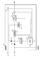
- FIG. 3 is a circuit diagram of the charge / discharge circuit 33.
- the charge / discharge circuit 33 includes switches 41 and 42, a detection circuit 43, and a resistor R1.
- the detection circuit 43 has resistors R2 and R3.
- One end of the switch 41 is connected to the cathodes of the diodes D1 and D2.
- the other end of the switch 41 is connected to one end of the resistor R1.
- One end of the switch 42 is connected to a connection node between the switch 41 and the resistor R1.
- the other end of the switch 42 is grounded.
- the other end of the resistor R1 is connected to one end of the battery 34 and one end of the resistor R2 included in the detection circuit 43.
- the other end of the resistor R2 is connected to one end of the resistor R3.
- the other end of the resistor R3 is grounded.
- a connection node between the resistors R2 and R3 is connected to the control unit 37.
- Each of the switches 41 and 42 functions as a first
- Each of the switches 41 and 42 is configured using a relay contact or a semiconductor element and is turned on or off by the control unit 37.
- the control unit 37 also functions as a switch control unit.
- the detection circuit 43 detects the terminal voltage of the battery 34.
- the resistors R2 and R3 divide the terminal voltage of the battery 34.
- the voltage divided by the resistors R2 and R3 is a detection voltage detected by the detection circuit 43, and is output from the detection circuit 43 to the control unit 37.
- the detection voltage is a predetermined number of the terminal voltage of the battery 34, for example, one third. Of course, the higher the terminal voltage of the battery 34, the higher the detection voltage.
- control unit 37 determines whether the switch 41, the switch 41, based on whether the ignition switch 22 is on, the content of the collision signal input from the output device 25, and the detection voltage input from the detection circuit 43. Each of the 42 is controlled on and off. The operation of the charge / discharge circuit 33 is controlled by controlling on and off of the switches 41 and 42.
- the battery 34 discharges power through the resistor R1 and the switch 42. In this manner, the charge / discharge circuit 33 causes the battery 34 to release electric power. At this time, power is consumed by the resistor R1. This discharge does not supply power to the load 24.
- the capacitor 34 is integrally charged and discharged using the same resistor R1.
- the power feeding device 23 having the charge / discharge circuit 33 and the control unit 37 is compared with a power feeding device in which a charging circuit that charges the battery 34 and a discharging circuit that discharges the battery 34 are configured separately. It is small and manufactured at low cost.
- the charge / discharge circuit 33 and the control unit 37 function as a charge / discharge device that charges and discharges the battery 34.
- the capacitor 34 also discharges power via the resistors R2 and R3 included in the detection circuit 43.
- the resistance value of the resistor R1 is sufficiently smaller than the combined resistance value of the resistors R2 and R3 included in the detection circuit 43.
- the resistance value of the resistor R1 is, for example, several ⁇ , and the resistance value of the combined resistance of the resistors R2 and R3 is, for example, several k ⁇ .
- the magnitude of the current flowing from the capacitor 34 to the resistor R1 is sufficiently larger than the magnitude of the current flowing from the capacitor 34 to the detection circuit 43.
- the power consumed by a resistor is calculated by the product of the square of the magnitude of the current flowing through the resistor and the resistance value. Therefore, the power consumed by the resistor R1 is sufficiently larger than the power consumed by the detection circuit 43.
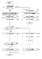
- FIG. 4 is a flowchart showing a procedure of control processing executed by the control unit 37.
- the control unit 37 operates and periodically executes control processing.
- the control unit 37 first determines whether or not the collision signal input from the output device 25 to the control unit 37 indicates a collision of the vehicle 1 (step S1). When it is determined that the collision signal input to the control unit 37 indicates a collision of the vehicle 1 (S1: YES), the control unit 37 turns off the switch 42 (step S2). Thereafter, the control unit 37 operates the DCDC converter 35 by outputting an operation instruction to the DCDC converter 35 (step S3). Next, the control unit 37 turns off the switch 31 (step S4) and turns on the switch 32 (step S5).
- the DCDC converter 35 transforms the terminal voltage of the battery 34 to the target voltage, and outputs the transformed voltage to the load 24 via the switch 32.
- the electric power stored in the capacitor 34 is supplied to the load 24. Therefore, even when the vehicle 1 collides and the battery 21 is lost, electric power is supplied from the battery 34 to the load 24, and the load 24 can operate.
- the switch 42 is kept off while the DC-DC converter 35 is transforming, the battery 34 does not discharge power through the resistor R1 and the switch 42.
- the control unit 37 ends the control process. Thereafter, the control unit 37 does not execute the control process again.
- the control unit 37 When it is determined that the collision signal input to the control unit 37 does not indicate a collision of the vehicle 1 (S1: NO), the control unit 37 outputs a stop instruction to the DCDC converter 35, thereby operating the DCDC converter 35. Is stopped (step S6). Next, the control unit 37 turns on the switch 31 (step S7) and turns off the switch 32 (step S8). Thereby, electric power is supplied from the battery 21 to the load 24 through the fuse F1 and the switch 31.
- the control unit 37 determines whether or not the ignition switch 22 is OFF based on the voltage at the anode of the diode D1 (step S9).
- the control unit 37 turns off the switch 41 (step S10).
- the switch 42 is turned on (step S11).
- the battery 34 discharges electric power via the resistor R1 and the switch 42, and a large amount of electric power is consumed by the resistor R1. At this time, no power is supplied to the load 24.
- the control part 37 complete
- the ignition switch 22 is off, power is supplied to the control unit 37 from the capacitor 34 via the diode D2 and the regulator 36 as described above.
- the control unit 37 keeps the switches 41 and 42 off and on while power is supplied from the battery 34 via the diode D2 and the regulator 36. To do.
- the control unit 37 stops operating, and the switches 41 and 42 are kept off and on, respectively.
- step S11 the switches 41 and 42 are kept off and on, and the charge / discharge circuit 33 uses the power stored in the battery 34. Continue to release. After executing step S11 and ending the control process, the control unit 37 continues to keep the switches 41 and 42 off and on as described above. Then, when the ignition switch 22 is switched from off to on, the control unit 37 executes the control process again.
- step S9 NO
- step S12 the control unit 37 turns off the switch 42 (step S12), and is input from the detection circuit 43. It is determined whether or not the terminal voltage of the battery 34 indicated by the detected voltage is less than a preset threshold value (step S13). Specifically, in step S13, the control unit 37 calculates the terminal voltage of the battery 34 based on the product of the detection voltage input from the detection circuit 43 and the predetermined number described above, and calculates the calculated terminal voltage and threshold value. Compare
- the control part 37 turns ON the switch 41, when it determines with the terminal voltage of the electrical storage device 34 being less than a threshold value (S13: YES) (step S14). Thereby, since each of the switches 41 and 42 is on and off, electric power is supplied from the charge / discharge circuit 33 to the battery 34, and the battery 34 is charged.
- control unit 37 determines that the terminal voltage of the battery 34 is equal to or higher than the threshold (S13: NO)
- the control unit 37 turns off the switch 41 (step S15). Thereby, since each of the switches 41 and 42 is off, the charge / discharge circuit 33 does not charge or discharge the battery 34.
- the control part 37 complete
- the terminal voltage of the battery 34 is less than the threshold value when the ignition switch 22 is on while the collision signal input to the control unit 37 does not indicate the collision of the vehicle 1. Is charged, and when the terminal voltage of the capacitor 34 is equal to or higher than the threshold, charging is stopped. Thereby, the terminal voltage of the battery 34 is maintained to be a threshold value.
- the switches 41 and 42 are turned off and on respectively, and the charge / discharge circuit 33 is The battery 34 is caused to discharge. At this time, since the electric power is discharged from the battery 34 via the resistor R1, the electric power stored in the battery 34 can be discharged in a short time.
- the period during which the ignition switch 22 is off is the longest during the period in which the battery 34 holds power without consuming power.
- the charging / discharging circuit 33 releases power to the battery 34. Therefore, the battery 34 is not allowed to be left for a long time with a large amount of power stored. Absent. For this reason, with respect to the battery 34, a decrease in the storage capacity and an increase in the internal resistance are suppressed. Even if the power supply to the control unit 37 is stopped while the battery 34 is discharging power, and the operation of the control unit 37 is stopped, the switches 41 and 42 are maintained off and on, respectively. , Almost all the electric power stored in the battery 34 can be consumed.
- control unit 37 determines in step S1 of the control process that the input collision signal indicates a collision of the vehicle 1, the control unit 37 turns off the switch 42 in step S2, and then switches the switch 42 in steps S3 to S5. None turn on. As a result, the control unit 37 keeps the switch 42 off when the collision signal input to the control unit 37 indicates a collision of the vehicle 1. For this reason, when the vehicle 1 collides, the electric power is sufficiently stored in the battery 34, and the load 24 can be operated using this electric power.
- the control unit 37 When the collision signal input to the control unit 37 indicates a collision of the vehicle 1, the control unit 37 operates the DCDC converter 35 to turn off and turn on the switches 31 and 32, respectively. Thereby, the electric power stored in the battery 34 is supplied to the load 24, and the load 24 can operate.
- the DCDC converter 35 may not be provided in the power feeding device 23.
- the charge / discharge circuit 33 has the terminal voltage of the capacitor 34 set to the threshold value.
- the battery 34 is charged so that When this threshold is higher than a voltage necessary for operating the load 24, it is not necessary to provide the DCDC converter 35 in the power feeding device 23. In this case, one end of the battery 34 is connected to one end of the switch 32.
- the switches 41 and 42 do not have to be kept off and on, for example, the switches 41 and 42 may be kept off.
- the control unit 37 keeps the switches 41 and 42 off and on only while the power is supplied to the control unit 37, and the battery 34 The electricity stored in is released. Thereafter, when the power supply to the control unit 37 is stopped, the switches 41 and 42 are turned off, and the discharging of the battery 34 via the resistor R1 is stopped.
- the battery 34 supplies power for operating each of the DCDC converter 35 and the regulator 36 via a lead wire (not shown).
- the number of capacitors is such that the voltage across the battery 34 can cause the DCDC converter 35 and the regulator 36 to operate.
- the number is preferably such that the battery 34 can be charged until the voltage becomes equal to or higher than the voltage.
- the number of capacitors connected in series is preferably 3 or more.
- Power supply device 33 Charge / discharge circuit (part of the charger / discharger) 34 Battery 35 DCDC converter (transformer) 37 Control unit (part of charger / discharger, switch control unit, determination unit, input unit) 41 switch (first switch) 42 switch (second switch) R1 resistance
Landscapes
- Engineering & Computer Science (AREA)
- Power Engineering (AREA)
- Mechanical Engineering (AREA)
- Business, Economics & Management (AREA)
- Emergency Management (AREA)
- Charge And Discharge Circuits For Batteries Or The Like (AREA)
- Control Of Charge By Means Of Generators (AREA)
Abstract
充放電回路(33)では、スイッチ(41)の一端に抵抗(R1)の一端が接続されている。スイッチ(41)及び抵抗(R1)間の接続ノードにスイッチ(42)の一端が接続されている。制御部(37)はスイッチ(41,42)夫々をオン又はオフにする。制御部(37)がスイッチ(41,42)夫々をオン及びオフにした場合、スイッチ(41)及び抵抗(R1)を介して、バッテリから蓄電器(34)に電力が供給される。制御部(37)がスイッチ(41,42)夫々をオフ及びオンにした場合、蓄電器(34)は抵抗(R1)及びスイッチ(42)を介して電力を放出する。
Description
本発明は、蓄電器の充電及び放電を行う充放電器、及び、該充放電器を備える給電装置に関する。
負荷に給電する給電装置として、蓄電器と、バッテリに蓄えられている電力を蓄電器に供給する充電回路とを備え、特定の場合、例えば、バッテリから負荷への電力供給が不可能となった場合に蓄電器に蓄えられた電力を負荷に供給する給電装置が提案されている。この給電装置では、例えば、蓄電器としてキャパシタが用いられる。
電力が蓄えられている状態でキャパシタを放置した場合、キャパシタの静電容量が低下し、キャパシタの内部抵抗が上昇する。ここで、キャパシタに蓄えられている電力が大きい程、即ち、キャパシタの両端間の電圧が高い程、静電容量が大きく低下し、キャパシタの内部抵抗は大きく上昇する。同様に、キャパシタが放置されている期間が長い程、静電容量が大きく低下し、キャパシタの内部抵抗は大きく上昇する。
静電容量が小さい程、一定の電圧が印加されているキャパシタに蓄えられている電力は小さい。このため、キャパシタに十分な電力を蓄えることができない虞がある。また、キャパシタの内部抵抗が大きい場合、キャパシタから電流が流れたときに内部抵抗で生じる電圧降下の幅が大きい。内部抵抗で大きく電圧が降下する場合、キャパシタから出力される電圧が低く、キャパシタから適切な電圧が出力されない虞がある。
特許文献1には、キャパシタの静電容量の低下、及び、内部抵抗の上昇を抑制することが可能な給電装置が開示されている。特許文献1に記載の給電装置は、充電回路の他に、負荷に電力を供給することなく、キャパシタが蓄えた電力を放出する放電回路を備える。放電回路が放電を適宜行う場合、大きな電力が蓄えられている状態でキャパシタが長期間放置されることはないため、キャパシタの静電容量の低下、及び、キャパシタの内部抵抗の上昇は抑制される。
蓄電器としてリチウムイオン電池又はニッケル水素電池等の電池が用いられた給電装置においても、電力が蓄えられている状態で蓄電器を放置した場合、蓄電器の蓄電容量が低下し、蓄電器の内部抵抗が上昇する。蓄電器としてキャパシタが用いられた場合と同様に、蓄電器に蓄えられている電力が大きい程、即ち、蓄電器の両端間の電圧が高い程、蓄電容量が大きく低下し、蓄電器の内部抵抗が大きく上昇する。更に、蓄電器が放置されている期間が長い程、蓄電容量が大きく低下し、蓄電器の内部抵抗が大きく上昇する。このため、蓄電器としてリチウムイオン電池又はニッケル水素電池等の電池が用いられた場合においても、蓄電器としてキャパシタが用いられた場合と同様に、蓄電器に十分な電圧を蓄えることができない虞と、蓄電器からキャパシタから適切な電圧を出力されない虞とがある。
蓄電器としてリチウムイオン電池又はニッケル水素電池等の電池が用いられた給電装置に関しても、特許文献1に開示されている給電装置と同様に、負荷に電力を供給することなく、蓄電器が蓄えた電力を放出する放電回路を備えることによって、蓄電容量の低下、及び、蓄電器の内部抵抗の上昇は抑制される。
しかしながら、特許文献1に記載されているような給電装置は、充電回路とは別に放電回路を備えている。このような給電装置には、サイズが大きく、製造費用が嵩むという問題がある。サイズが大きい装置は、空間が限定的である車両に搭載される装置として好ましくない。
本発明は斯かる事情に鑑みてなされたものであり、その目的とするところは、蓄電器の充電及び放電を一体的に行うことができる充放電器、及び、該充放電器を備える給電装置を提供することにある。
本発明に係る充放電器は、蓄電器の充電及び放電を行う充放電器において、第1スイッチと、該第1スイッチの一端に一端が接続されている抵抗と、前記第1スイッチ及び抵抗間の接続ノードに一端が接続されている第2スイッチと、前記第1スイッチ及び第2スイッチ夫々をオン又はオフにするスイッチ制御部とを備え、該スイッチ制御部が前記第1スイッチ及び第2スイッチ夫々をオン及びオフにした場合、前記第1スイッチ及び抵抗を介して前記蓄電器に電力が供給され、前記スイッチ制御部が前記第1スイッチ及び第2スイッチ夫々をオフ及びオンにした場合、前記蓄電器は前記抵抗及び第2スイッチを介して電力を放出することを特徴とする。
本発明にあっては、第1スイッチの一端に抵抗の一端が接続されている。第1スイッチ及び抵抗間の接続ノードに第2スイッチが接続されている。第1スイッチ及び第2スイッチ夫々をオン及びオフにした場合、例えば、バッテリから第1スイッチ及び抵抗を介して蓄電器に電力が供給され、蓄電器は充電される。また、第1スイッチ及び第2スイッチ夫々をオフ及びオンにした場合、蓄電器は抵抗及び第2スイッチを介して電力を放出し、抵抗で電力が消費される。
このように、同一の抵抗を用いて、蓄電器の充電及び放電が一体的に行われる。
このように、同一の抵抗を用いて、蓄電器の充電及び放電が一体的に行われる。
本発明に係る充放電器は、車両のイグニッションスイッチがオフであるか否かを判定する判定部を備え、前記スイッチ制御部は、該判定部によって、前記イグニッションスイッチがオフであると判定された場合に前記第1スイッチ及び第2スイッチをオフ及びオンにすることを特徴とする。
本発明にあっては、車両のイグニッションスイッチがオフであると判定した場合、言い換えると、車両のエンジンが停止していると判定した場合、第1スイッチ及び第2スイッチをオフ及びオンにする。これにより、蓄電器は放電する。蓄電器が放電しない構成では、蓄電器が電力を供給する対象が、イグニッションスイッチがオンである間に作動する負荷である場合、電力を消費することなく蓄電器が電力を保持している期間の中で、イグニッションスイッチがオフである期間が最も長いと想定される。本発明では、イグニッションスイッチがオフである場合に蓄電器が放電するため、大きな電力が蓄えられている状態で蓄電器が長期間放置されることはない。
本発明に係る充放電器は、車両が衝突したか否かを示す衝突信号が入力される入力部を備え、前記スイッチ制御部は、該入力部に入力された衝突信号が前記車両の衝突を示した場合、前記第2スイッチをオフに維持することを特徴とする。
本発明にあっては、入力部に入力された衝突信号が車両の衝突を示している場合、第2スイッチはオフに維持され、蓄電器が抵抗を介して電力を放出することはない。従って、車両が衝突した場合において、蓄電器に電力が十分に蓄えられている。このため、車両が衝突した場合に、蓄電器に蓄えられている電力を用いて負荷を作動させることが可能となる。
本発明に係る充放電器は、前記スイッチ制御部が動作を停止した場合、前記第1スイッチ及び第2スイッチ夫々はオフ及びオンに維持されることを特徴とする。
本発明にあっては、例えば給電の停止によって、スイッチ制御部が動作を停止した場合、第1スイッチ及び第2スイッチ夫々はオフ及びオンに維持され、蓄電器の放電が行われる。
本発明に係る給電装置は、前述した充放電器と、前記蓄電器とを備え、該蓄電器が蓄えられている電力が供給されることを特徴とする。
本発明にあっては、前述した充放電器は蓄電器の充電及び放電を行う。蓄電器に蓄えられている電力が負荷に供給される。蓄電器の充電及び放電を一体的に行う充放電器を備えるため、装置が小型であり、製造費用が安価である。
本発明に係る給電装置は、前記蓄電器の端子電圧を変圧し、変圧した電圧を出力する変圧部を備えることを特徴とする。
本発明にあっては、変圧部は、蓄電器の端子電圧を変圧し、変圧した電圧を負荷に出力する。これにより、蓄電器に蓄えられている電力が負荷に供給される。
本発明によれば、蓄電器の充電及び放電を一体的に行うことができる。
以下、本発明をその実施の形態を示す図面に基づいて詳述する。
図1は、本実施の形態における車両1に搭載された電源システム2の要部構成を示すブロック図である。電源システム2は、バッテリ21、イグニッションスイッチ22、給電装置23、負荷24、出力装置25及びヒューズF1,F2を備える。バッテリ21の正極は、イグニッションスイッチ22及びヒューズF1夫々の一端に接続されている。バッテリ21の負極は接地されている。イグニッションスイッチ22の他端はヒューズF2の一端に接続されている。ヒューズF1,F2夫々の他端と、負荷24の一端とは給電装置23に各別に接続されている。負荷24の他端は接地されている。
図1は、本実施の形態における車両1に搭載された電源システム2の要部構成を示すブロック図である。電源システム2は、バッテリ21、イグニッションスイッチ22、給電装置23、負荷24、出力装置25及びヒューズF1,F2を備える。バッテリ21の正極は、イグニッションスイッチ22及びヒューズF1夫々の一端に接続されている。バッテリ21の負極は接地されている。イグニッションスイッチ22の他端はヒューズF2の一端に接続されている。ヒューズF1,F2夫々の他端と、負荷24の一端とは給電装置23に各別に接続されている。負荷24の他端は接地されている。
バッテリ21は、例えば、鉛蓄電池であり、車両1の図示しないエンジンと連動して発電する図示しない発電機から供給された直流の電力を蓄える。バッテリ21は、ヒューズF1を介して電力を給電装置23に出力する。バッテリ21は、更に、イグニッションスイッチ22がオンである場合、イグニッションスイッチ22及びヒューズF2を介して電力を給電装置23に出力する。
イグニッションスイッチ22は、エンジンが作動している場合にオンであり、エンジンが動作を停止している場合にオフである。
イグニッションスイッチ22は、エンジンが作動している場合にオンであり、エンジンが動作を停止している場合にオフである。
給電装置23は、イグニッションスイッチ22がオンである場合、イグニッションスイッチ22及びヒューズF2を介して、バッテリ21から出力された電力を蓄える。
給電装置23には、出力装置25から車両1が衝突したか否かを示す衝突信号が入力される。
出力装置25は、例えば、エアバッグを制御するECU(Electronic Control Unit)である。出力装置25は車両1が衝突したか否かを判定する。出力装置25は、車両1が衝突していないと判定した場合、車両1が衝突していないことを示す衝突信号を給電装置23に出力し、車両1が衝突したと判定した場合、車両1の衝突を示す衝突信号を給電装置23に出力する。出力装置25は、例えば、車両1の加速度を検出する加速度センサを有し、加速度センサの検出結果に基づいて、車両1が衝突したか否かを判定する。
出力装置25は、例えば、エアバッグを制御するECU(Electronic Control Unit)である。出力装置25は車両1が衝突したか否かを判定する。出力装置25は、車両1が衝突していないと判定した場合、車両1が衝突していないことを示す衝突信号を給電装置23に出力し、車両1が衝突したと判定した場合、車両1の衝突を示す衝突信号を給電装置23に出力する。出力装置25は、例えば、車両1の加速度を検出する加速度センサを有し、加速度センサの検出結果に基づいて、車両1が衝突したか否かを判定する。
給電装置23は、出力装置25から入力された衝突信号が車両1の衝突を示していない場合、ヒューズF1を介して、バッテリ21から入力された電力を負荷24に供給する。給電装置23は、出力装置25から入力された衝突信号が車両1の衝突を示す場合、蓄えた電力を負荷24に供給する。
負荷24は、車両1が衝突してバッテリ21が喪失された場合であっても作動する必要がある電気機器であり、例えば、車両1のドアのロック及びアンロックを行うモータである。負荷24は、イグニッションスイッチ22がオンである間、即ち、車両1のエンジンが作動している間に作動するように構成されている。負荷24には、給電装置23から電力が供給される。負荷24は、給電装置23から供給された電力を用いて動作を行う。
図2は給電装置23の要部構成を示すブロック図である。給電装置23は、スイッチ31,32、充放電回路33、蓄電器34、DCDCコンバータ35、レギュレータ36、制御部37及びダイオードD1,D2を有する。
スイッチ31の一端はヒューズF1の他端に接続されている。スイッチ31の他端は負荷24の一端に接続されている。ダイオードD1のアノードはヒューズF2の他端に接続されている。ダイオードD1のカソードは、ダイオードD2のカソードと、充放電回路33とに接続されている。充放電回路33は、更に、蓄電器34の一端に接続されている。充放電回路33と蓄電器34の他端とは接地されている。
蓄電器34の一端は、更に、ダイオードD2のアノードと、DCDCコンバータ35とに接続されている。DCDCコンバータ35は、更に、スイッチ32の一端に接続されている。スイッチ32の他端は負荷24の一端に接続されている。ダイオードD1,D2夫々のカソード間の接続ノードはレギュレータ36の入力端に接続されている。レギュレータ36の出力端は制御部37に接続されている。制御部37は、更に、充放電回路33と、ダイオードD1のアノードとに接続されている。
スイッチ31は、リレー接点又は半導体素子等を用いて構成され、制御部37によってオン又はオフにされる。制御部37が動作を停止している場合、スイッチ31はオンに維持される。スイッチ31がオンである場合、バッテリ21から、ヒューズF1及びスイッチ31を介して、負荷24に電力が供給される。
スイッチ32は、リレー接点又は半導体素子等を用いて構成され、制御部37によってオン又はオフにされる。制御部37が動作を停止している場合、スイッチ32はオフに維持される。
充放電回路33は蓄電器34の充電及び放電を行う。充放電回路33の動作は制御部37によって制御される。充放電回路33の動作については後述する。
蓄電器34は、例えば、直列に接続された複数の図示しないキャパシタによって構成される。この場合、複数のキャパシタによって構成される直列回路の一端は、充電回路33と、DCDCコンバータ35と、ダイオードD2のアノードとに接続されている。該直列回路の他端は接地されている。キャパシタは例えば電気二重層キャパシタである。また、蓄電器34は、キャパシタではなく、リチウムイオン電池又はニッケル水素電池等の電池によって構成されてもよい。
DCDCコンバータ35には制御部37から作動指示及び停止指示が入力される。DCDCコンバータ35は、制御部37から作動指示が入力された場合、蓄電器34の端子電圧を、予め設定されている目標電圧に変圧し、変圧した電圧を、スイッチ32を介して負荷24に出力する。これにより、負荷24に電力が供給される。DCDCコンバータ35は変圧部として機能する。
レギュレータ36の入力端には、ダイオードD1,D2夫々のアノードにおける電圧の中で高い電圧が入力される。バッテリ21が喪失されておらず、かつ、イグニッションスイッチ22がオンである場合、バッテリ21がイグニッションスイッチ22及びヒューズF2を介して出力する電圧は、蓄電器34の端子電圧よりも高い。従って、バッテリ21が喪失されておらず、かつ、イグニッションスイッチ22がオンである場合、バッテリ21が出力した電圧はダイオードD1を介してレギュレータ36の入力端に入力される。バッテリ21が喪失されているか、又は、イグニッションスイッチがオフである場合、ダイオードD1のアノードは開放されているため、蓄電器34の端子電圧がダイオードD2を介してレギュレータ36の入力端に入力される。
レギュレータ36は、ダイオードD1,D2の1つを介して入力された電圧を、制御部37を作動させるために必要な作動電圧、例えば5Vに降圧し、降圧した電圧を出力端から制御部37に出力する。これにより、制御部37には電力が供給される。作動電圧は予め設定されている一定電圧である。
バッテリ21が喪失されておらず、かつ、イグニッションスイッチ22がオンである場合、レギュレータ36はダイオードD1のアノードにおける電圧を作動電圧に降圧するので、制御部37には、バッテリ21からダイオードD1及びレギュレータ36を介して電力が供給される。バッテリ21が喪失されている場合、又は、イグニッションスイッチ22がオフである場合、レギュレータ36はダイオードD2のアノードにおける電圧を作動電圧に降圧するので、制御部37には、蓄電器34からダイオードD2及びレギュレータ36を介して電力が供給される。
制御部37はレギュレータ36から電力が供給された場合に作動する。制御部37には、ダイオードD1のアノードにおける電圧が入力される。制御部37は、ダイオードD1のアノードにおける電圧に基づいて、車両1のイグニッションスイッチ22がオフであるか否かを判定する。制御部37は、ダイオードD1のアノードにおける電圧が予め設定されている基準電圧未満である場合、イグニッションスイッチ22がオフであると判定する。制御部37は、ダイオードD1のアノードにおける電圧が基準電圧以上である場合、イグニッションスイッチ22がオンであると判定する。基準電圧は、ゼロVよりも高く、バッテリ21の出力電圧より低い一定の電圧である。制御部37は判定部として機能する。
制御部37には出力装置25から衝突信号が入力される。制御部37は入力部としても機能する。
制御部37は、出力装置25から入力された衝突信号が示す内容に基づいて、スイッチ31,32夫々のオン及びオフと、DCDCコンバータ35の作動及び停止とを制御にする。更に、制御部37は、イグニッションスイッチ22がオンであるか否かと、出力装置25から入力された衝突信号が示す内容とに基づいて、充放電回路33の動作を制御する。
制御部37は、出力装置25から入力された衝突信号が示す内容に基づいて、スイッチ31,32夫々のオン及びオフと、DCDCコンバータ35の作動及び停止とを制御にする。更に、制御部37は、イグニッションスイッチ22がオンであるか否かと、出力装置25から入力された衝突信号が示す内容とに基づいて、充放電回路33の動作を制御する。
制御部37は、図示しないCPU(Central Processing Unit)を有し、図示しないメモリに記憶されている制御プログラムを実行することによって、スイッチ31,32夫々のオン及びオフと、DCDCコンバータ35の作動及び停止と、充放電回路33の動作とを制御する制御処理を実行する。
レギュレータ36から制御部37への電力供給が停止した場合、制御部37は動作を停止する。
レギュレータ36から制御部37への電力供給が停止した場合、制御部37は動作を停止する。
図3は充放電回路33の回路図である。充放電回路33はスイッチ41,42、検出回路43及び抵抗R1を有する。検出回路43は抵抗R2,R3を有する。スイッチ41の一端はダイオードD1,D2夫々のカソードに接続されている。スイッチ41の他端は抵抗R1の一端に接続されている。スイッチ41及び抵抗R1間の接続ノードにスイッチ42の一端が接続されている。スイッチ42の他端は接地されている。抵抗R1の他端は、蓄電器34の一端と、検出回路43が有する抵抗R2の一端とに接続されている。検出回路43において、抵抗R2の他端は、抵抗R3の一端に接続されている。抵抗R3の他端は接地されている。抵抗R2,R3間の接続ノードは制御部37に接続されている。
スイッチ41,42夫々は第1スイッチ及び第2スイッチとして機能する。
スイッチ41,42夫々は第1スイッチ及び第2スイッチとして機能する。
スイッチ41,42夫々は、リレー接点又は半導体素子等を用いて構成され、制御部37によってオン又はオフにされる。制御部37はスイッチ制御部としても機能する。
検出回路43は蓄電器34の端子電圧を検出する。検出回路43において、抵抗R2,R3は蓄電器34の端子電圧を分圧する。抵抗R2,R3が分圧した電圧は、検出回路43によって検出された検出電圧であり、検出回路43から制御部37に出力される。検出電圧は、蓄電器34の端子電圧の所定数分の1、例えば3分の1である。当然のことながら、蓄電器34の端子電圧が高い程、検出電圧も高い。
検出回路43は蓄電器34の端子電圧を検出する。検出回路43において、抵抗R2,R3は蓄電器34の端子電圧を分圧する。抵抗R2,R3が分圧した電圧は、検出回路43によって検出された検出電圧であり、検出回路43から制御部37に出力される。検出電圧は、蓄電器34の端子電圧の所定数分の1、例えば3分の1である。当然のことながら、蓄電器34の端子電圧が高い程、検出電圧も高い。
制御部37は、制御処理において、イグニッションスイッチ22がオンであるか否かと、出力装置25から入力された衝突信号の内容と、検出回路43から入力された検出電圧とに基づいて、スイッチ41,42夫々のオン及びオフを制御する。スイッチ41,42夫々のオン及びオフを制御することによって、充放電回路33の動作が制御される。
バッテリ21が喪失されておらず、かつ、イグニッションスイッチ22がオンである場合において、制御部37がスイッチ41,42夫々をオン及びオフにしたとき、充放電回路33は、バッテリ21からイグニッションスイッチ22、ヒューズF2、スイッチ41及び抵抗R1を介して蓄電器34に電力を供給する。これにより、蓄電器34は充電される。
制御部37がスイッチ41,42夫々をオフ及びオンにした場合、蓄電器34は、抵抗R1及びスイッチ42を介して電力を放出する。このように、充放電回路33は蓄電器34に電力を放出させる。このとき、電力は抵抗R1によって消費される。この放電によって、負荷24に電力が供給されることはない。
以上のように、充放電回路33では、同一の抵抗R1を用いて、蓄電器34の充電及び放電が一体的に行われる。このため、充放電回路33及び制御部37を有する給電装置23は、蓄電器34の充電を行う充電回路と、蓄電器34の放電を行う放電回路とが別々に構成された給電装置と比較して、小型であり、安価に製造される。
充放電回路33及び制御部37は、蓄電器34の充電及び放電を行う充放電器として機能する。
充放電回路33及び制御部37は、蓄電器34の充電及び放電を行う充放電器として機能する。
蓄電器34は、検出回路43が有する抵抗R2,R3を介しても電力を放出する。しかしながら、抵抗R1の抵抗値は、検出回路43が有する抵抗R2,R3の合成抵抗の抵抗値よりも十分に小さい。抵抗R1の抵抗値は例えば数Ωであり、抵抗R2,R3の合成抵抗の抵抗値は例えば数kΩである。
このため、スイッチ41,42夫々がオフ及びオンである場合において、蓄電器34から抵抗R1に流れる電流の大きさは、蓄電器34から検出回路43に流れる電流の大きさよりも十分に大きい。一般に、抵抗で消費される電力は、この抵抗に流れる電流の大きさの2乗と、抵抗値との積によって算出される。従って、抵抗R1で消費される電力は、検出回路43で消費される電力よりも十分に大きい。結果、スイッチ41,42をオフ及びオンにした場合、抵抗R1で大量の電力が消費されるので、蓄電器34に蓄えられている電力を短時間で消費することができる。
制御部37がスイッチ41,42夫々をオフにした場合、抵抗R1を介した蓄電器34への電力供給、及び、抵抗R1を介した蓄電器34の放電が行われることはない。
制御部37が動作を停止した場合、スイッチ41,42はオフ及びオンに維持される。スイッチ41,42がオフ及びオンである場合、前述したように、蓄電器34は、抵抗R1及びスイッチ42を介して電力を放出する。
図4は制御部37が実行する制御処理の手順を示すフローチャートである。バッテリ21が喪失されていない状態でエンジンが作動してイグニッションスイッチ22がオンとなった場合、バッテリ21からイグニッションスイッチ22、ヒューズF2、ダイオードD1及びレギュレータ36を介して制御部37に電力が供給される。この電力供給によって、制御部37は作動し、制御処理を周期的に実行する。
制御処理では、制御部37は、まず、出力装置25から制御部37に入力された衝突信号が車両1の衝突を示しているか否かを判定する(ステップS1)。制御部37は、制御部37に入力された衝突信号が車両1の衝突を示していると判定した場合(S1:YES)、スイッチ42をオフにする(ステップS2)。その後、制御部37は、DCDCコンバータ35に作動指示を出力することによって、DCDCコンバータ35を作動させる(ステップS3)。次に、制御部37は、スイッチ31をオフにし(ステップS4)、スイッチ32をオンにする(ステップS5)。
これにより、DCDCコンバータ35は、蓄電器34の端子電圧を目標電圧に変圧し、変圧した電圧を、スイッチ32を介して負荷24に出力する。DCDCコンバータ35が変圧した電圧を負荷24に出力することによって、蓄電器34に蓄えてられている電力が負荷24に供給される。従って、車両1が衝突してバッテリ21が喪失された場合であっても、蓄電器34から負荷24に電力が供給され、負荷24は作動することが可能である。DCDCコンバータ35が変圧を行っている間、スイッチ42はオフに維持されているため、蓄電器34は、抵抗R1及びスイッチ42を介して電力を放出することはない。
制御部37は、ステップS5を実行した後、制御処理を終了する。この後、制御部37は制御処理を再び実行することはない。
制御部37は、ステップS5を実行した後、制御処理を終了する。この後、制御部37は制御処理を再び実行することはない。
制御部37は、制御部37に入力された衝突信号が車両1の衝突を示していないと判定した場合(S1:NO)、DCDCコンバータ35に停止指示を出力することによって、DCDCコンバータ35に動作を停止させる(ステップS6)。次に、制御部37は、スイッチ31をオンにし(ステップS7)、スイッチ32をオフにする(ステップS8)。これにより、バッテリ21からヒューズF1及びスイッチ31を介して負荷24に電力が供給される。
次に、制御部37は、前述したように、ダイオードD1のアノードにおける電圧に基づいて、イグニッションスイッチ22がオフであるか否かを判定する(ステップS9)。制御部37は、イグニッションスイッチ22がオフであると判定した場合、即ち、車両1が衝突していない状態でエンジンが停止したと判定した場合(S9:YES)、スイッチ41をオフにし(ステップS10)、スイッチ42をオンにする(ステップS11)。
これにより、蓄電器34は抵抗R1及びスイッチ42を介して電力を放出し、抵抗R1で大量の電力が消費される。このとき、負荷24には電力が供給されることはない。
制御部37は、ステップS11を実行した後、制御処理を終了する。
イグニッションスイッチ22がオフである場合、前述したように、制御部37には、蓄電器34からダイオードD2及びレギュレータ36を介して電力が供給される。制御部37は、ステップS11を実行して制御処理を終了した後においては、ダイオードD2及びレギュレータ36を介して蓄電器34から電力が供給されている間、スイッチ41,42夫々をオフ及びオンに維持する。蓄電器34から制御部37への電力供給が停止した場合、制御部37は動作を停止し、スイッチ41,42夫々はオフ及びオンに維持される。
イグニッションスイッチ22がオフである場合、前述したように、制御部37には、蓄電器34からダイオードD2及びレギュレータ36を介して電力が供給される。制御部37は、ステップS11を実行して制御処理を終了した後においては、ダイオードD2及びレギュレータ36を介して蓄電器34から電力が供給されている間、スイッチ41,42夫々をオフ及びオンに維持する。蓄電器34から制御部37への電力供給が停止した場合、制御部37は動作を停止し、スイッチ41,42夫々はオフ及びオンに維持される。
従って、制御部37がステップS11を実行してからイグニッションスイッチ22が再びオンとなるまで、スイッチ41,42夫々はオフ及びオンに維持され、充放電回路33は、蓄電器34が蓄えている電力を放出し続ける。
制御部37は、ステップS11を実行して制御処理を終了した後、前述したようにスイッチ41,42夫々をオフ及びオンに維持し続ける。そして、イグニッションスイッチ22がオフからオンに切替わった場合に制御部37は制御処理を再び実行する。
制御部37は、ステップS11を実行して制御処理を終了した後、前述したようにスイッチ41,42夫々をオフ及びオンに維持し続ける。そして、イグニッションスイッチ22がオフからオンに切替わった場合に制御部37は制御処理を再び実行する。
制御部37は、イグニッションスイッチ22がオフではない、即ち、イグニッションスイッチ22がオンであると判定した場合(ステップS9:NO)、スイッチ42をオフにし(ステップS12)、検出回路43から入力された検出電圧が示す蓄電器34の端子電圧が予め設定されている閾値未満であるか否かを判定する(ステップS13)。具体的には、制御部37は、ステップS13において、検出回路43から入力された検出電圧と、前述した所定数との積によって、蓄電器34の端子電圧を算出し、算出した端子電圧と閾値とを比較する。
制御部37は、蓄電器34の端子電圧が閾値未満であると判定した場合(S13:YES)、スイッチ41をオンにする(ステップS14)。これにより、スイッチ41,42夫々がオン及びオフであるので、充放電回路33から蓄電器34に電力が供給され、蓄電器34は充電される。
制御部37は、蓄電器34の端子電圧が閾値以上であると判定した場合(S13:NO)、スイッチ41をオフにする(ステップS15)。これにより、スイッチ41,42夫々はオフであるので、充放電回路33は蓄電器34の充電及び放電のいずれも行わない。
制御部37は、ステップS14,S15のいずれかを実行した後、制御処理を終了する。この場合においては、制御部37は、次の周期が到来した場合、再び制御処理を実行する。
以上のように、充放電回路33は、制御部37に入力されている衝突信号が車両1の衝突を示していない状態でイグニッションスイッチ22がオンである場合において、蓄電器34の端子電圧が閾値未満であるときに蓄電器34を充電し、蓄電器34の端子電圧が閾値以上であるとき、充電を停止する。これにより、蓄電器34の端子電圧は閾値となるように維持される。
制御部37に入力されている衝突信号が車両1の衝突を示していない状態でイグニッションスイッチ22がオンからオフに切替わった場合、スイッチ41,42夫々はオフ及びオンとなり、充放電回路33は蓄電器34に放電を行わせる。このとき、抵抗R1を介して、蓄電器34から電力が放出されるため、蓄電器34が蓄えている電力を短時間で放出することができる。
蓄電器34が放電しない構成では、電力を消費することなく蓄電器34が電力を保持している期間の中で、イグニッションスイッチ22がオフである期間が最も長いと想定される。本実施の形態では、充放電回路33は、イグニッションスイッチ22がオフである場合に、蓄電器34に電力を放出させるため、大きな電力が蓄えられている状態で蓄電器34が長期間放置されることはない。このため、蓄電器34に関して、蓄電容量の低下と内部抵抗の上昇とが抑制される。
蓄電器34が電力を放出している途中で制御部37への電力供給が停止して制御部37の動作が停止した場合であっても、スイッチ41,42夫々がオフ及びオンに維持されるので、蓄電器34が蓄えている略全ての電力を消費することができる。
蓄電器34が電力を放出している途中で制御部37への電力供給が停止して制御部37の動作が停止した場合であっても、スイッチ41,42夫々がオフ及びオンに維持されるので、蓄電器34が蓄えている略全ての電力を消費することができる。
また、制御部37は、制御処理のステップS1で、入力されている衝突信号が車両1の衝突を示したと判定した場合、ステップS2でスイッチ42をオフにし、その後、ステップS3~S5でスイッチ42をオンにすることはない。結果、制御部37は、制御部37に入力された衝突信号が車両1の衝突を示した場合、スイッチ42をオフに維持する。このため、車両1が衝突した場合において、蓄電器34に電力が十分に蓄えられており、この電力を用いて負荷24を作動させることができる。
制御部37は、制御部37に入力されている衝突信号が車両1の衝突を示した場合、DCDCコンバータ35を作動させ、スイッチ31,32夫々をオフ及びオンにする。これにより、蓄電器34に蓄えられている電力が負荷24に供給され、負荷24は動作を行うことが可能となる。
なお、給電装置23にDCDCコンバータ35が設けられていなくてもよい。前述したように、制御部37に入力された衝突信号が車両1の衝突を示していない状態で、車両1のイグニッションスイッチ22がオフである場合、充放電回路33は蓄電器34の端子電圧が閾値となるように蓄電器34を充電する。この閾値が負荷24を作動させるために必要な電圧よりも高い場合、給電装置23にDCDCコンバータ35が設けられている必要はない。この場合、蓄電器34の一端はスイッチ32の一端に接続される。
また、制御部37が動作を停止した場合にスイッチ41,42夫々はオフ及びオンに維持されなくてもよく、例えば、スイッチ41,42夫々はオフに維持されてもよい。この場合、制御部37は、ステップS10,S11を実行して制御処理を終了した後、制御部37へ電力が供給されている間だけスイッチ41,42夫々をオフ及びオンに維持し、蓄電器34に蓄えられている電力が放出される。その後、制御部37への電力供給が停止した場合、スイッチ41,42夫々はオフとなり、抵抗R1を介した蓄電器34の放電が停止する。
この場合であっても、放電が停止された時点において、蓄電器34が蓄えられている電力は小さいため、蓄電器34の放置による蓄電器34の蓄電容量の低下及び内部抵抗の上昇が抑制される。
バッテリ21が喪失された場合、蓄電器34は、図示しない導線を介してDCDCコンバータ35及びレギュレータ36夫々に動作を行うための電力を供給する。蓄電器34が直列に接続された複数のキャパシタによって構成されている場合においては、キャパシタの数は、蓄電器34の両端間の電圧が、DCDCコンバータ35及びレギュレータ36夫々に動作を行わせることが可能な電圧以上となるまで蓄電器34を充電することができる数であることが好ましい。例えば、6V以上の電圧の印加でDCDCコンバータ35及びレギュレータ36が動作し、1つのキャパシタの耐圧が2.5Vである場合、直列に接続されるキャパシタの数は3個以上であることが好ましい。
開示された実施の形態は全ての点で例示であって、制限的なものではないと考えられるべきである。本発明の範囲は、上記した意味ではなく、請求の範囲によって示され、請求の範囲と均等の意味及び範囲内での全ての変更が含まれることが意図される。
22 給電装置
33 充放電回路(充放電器の一部)
34 蓄電器
35 DCDCコンバータ(変圧部)
37 制御部(充放電器の一部、スイッチ制御部、判定部、入力部)
41 スイッチ(第1スイッチ)
42 スイッチ(第2スイッチ)
R1 抵抗
33 充放電回路(充放電器の一部)
34 蓄電器
35 DCDCコンバータ(変圧部)
37 制御部(充放電器の一部、スイッチ制御部、判定部、入力部)
41 スイッチ(第1スイッチ)
42 スイッチ(第2スイッチ)
R1 抵抗
Claims (6)
- 蓄電器の充電及び放電を行う充放電器において、
第1スイッチと、
該第1スイッチの一端に一端が接続されている抵抗と、
前記第1スイッチ及び抵抗間の接続ノードに一端が接続されている第2スイッチと、
前記第1スイッチ及び第2スイッチ夫々をオン又はオフにするスイッチ制御部と
を備え、
該スイッチ制御部が前記第1スイッチ及び第2スイッチ夫々をオン及びオフにした場合、前記第1スイッチ及び抵抗を介して前記蓄電器に電力が供給され、
前記スイッチ制御部が前記第1スイッチ及び第2スイッチ夫々をオフ及びオンにした場合、前記蓄電器は前記抵抗及び第2スイッチを介して電力を放出すること
を特徴とする充放電器。 - 車両のイグニッションスイッチがオフであるか否かを判定する判定部を備え、
前記スイッチ制御部は、該判定部によって、前記イグニッションスイッチがオフであると判定された場合に前記第1スイッチ及び第2スイッチをオフ及びオンにすること
を特徴とする請求項1に記載の充放電器。 - 車両が衝突したか否かを示す衝突信号が入力される入力部を備え、
前記スイッチ制御部は、該入力部に入力された衝突信号が前記車両の衝突を示した場合、前記第2スイッチをオフに維持すること
を特徴とする請求項1又は請求項2に記載の充放電器。 - 前記スイッチ制御部が動作を停止した場合、前記第1スイッチ及び第2スイッチ夫々はオフ及びオンに維持されること
を特徴とする請求項1から請求項3のいずれか1つに記載の充放電器。 - 請求項1から請求項4のいずれか1つに記載の充放電器と、
前記蓄電器と
を備え、
該蓄電器が蓄えられている電力が供給されること
を特徴とする給電装置。 - 前記蓄電器の端子電圧を変圧し、変圧した電圧を出力する変圧部を備えること
を特徴とする請求項5に記載の給電装置。
Applications Claiming Priority (2)
| Application Number | Priority Date | Filing Date | Title |
|---|---|---|---|
| JP2015144924A JP6176292B2 (ja) | 2015-07-22 | 2015-07-22 | 充放電器及び給電装置 |
| JP2015-144924 | 2015-07-22 |
Publications (1)
| Publication Number | Publication Date |
|---|---|
| WO2017014045A1 true WO2017014045A1 (ja) | 2017-01-26 |
Family
ID=57833937
Family Applications (1)
| Application Number | Title | Priority Date | Filing Date |
|---|---|---|---|
| PCT/JP2016/069864 Ceased WO2017014045A1 (ja) | 2015-07-22 | 2016-07-05 | 充放電器及び給電装置 |
Country Status (2)
| Country | Link |
|---|---|
| JP (1) | JP6176292B2 (ja) |
| WO (1) | WO2017014045A1 (ja) |
Citations (3)
| Publication number | Priority date | Publication date | Assignee | Title |
|---|---|---|---|---|
| JP2006246569A (ja) * | 2005-03-01 | 2006-09-14 | Mitsubishi Motors Corp | 車両の電力制御装置 |
| WO2007122671A1 (ja) * | 2006-04-12 | 2007-11-01 | Mitsubishi Denki Kabushiki Kaisha | 電気車の制御装置 |
| JP2013146116A (ja) * | 2012-01-13 | 2013-07-25 | Ntn Corp | 電気自動車のコンデンサ電荷放電装置 |
-
2015
- 2015-07-22 JP JP2015144924A patent/JP6176292B2/ja not_active Expired - Fee Related
-
2016
- 2016-07-05 WO PCT/JP2016/069864 patent/WO2017014045A1/ja not_active Ceased
Patent Citations (3)
| Publication number | Priority date | Publication date | Assignee | Title |
|---|---|---|---|---|
| JP2006246569A (ja) * | 2005-03-01 | 2006-09-14 | Mitsubishi Motors Corp | 車両の電力制御装置 |
| WO2007122671A1 (ja) * | 2006-04-12 | 2007-11-01 | Mitsubishi Denki Kabushiki Kaisha | 電気車の制御装置 |
| JP2013146116A (ja) * | 2012-01-13 | 2013-07-25 | Ntn Corp | 電気自動車のコンデンサ電荷放電装置 |
Also Published As
| Publication number | Publication date |
|---|---|
| JP6176292B2 (ja) | 2017-08-09 |
| JP2017028858A (ja) | 2017-02-02 |
Similar Documents
| Publication | Publication Date | Title |
|---|---|---|
| CN114552753B (zh) | 车载用的备用控制装置及车载用的备用装置 | |
| CN109792160B (zh) | 车载用的备用装置 | |
| JP5808678B2 (ja) | 電動車両 | |
| JP6969505B2 (ja) | 車載用の電源制御装置および車載用電源システム | |
| CN108462246A (zh) | 供电系统 | |
| CN110365098A (zh) | 供电装置 | |
| JP6387940B2 (ja) | 車載用電源装置 | |
| US11066027B2 (en) | In-vehicle power supply apparatus configured to charge a plurality of batteries | |
| JP2018164323A (ja) | 車載用の制御装置及び車載用電源装置 | |
| KR20200039797A (ko) | 하나 이상의 리튬 이온 전지를 구비한 에너지 저장기의 전해 연마를 위한 장치, 충전 장치, 및 충전 장치의 작동 방법 | |
| JP2012080723A (ja) | 車両用電源装置 | |
| JP2010048123A (ja) | 車両用電源装置 | |
| JP6176292B2 (ja) | 充放電器及び給電装置 | |
| JP6406188B2 (ja) | 車載用電源装置 | |
| US11876400B2 (en) | Backup power-supply device | |
| JP6587432B2 (ja) | オルタネータの発電制御装置 | |
| JP5482816B2 (ja) | 電力制御装置 | |
| JP6855321B2 (ja) | 異常判定装置および異常判定方法 | |
| JP2017112672A (ja) | 車載型充電装置 | |
| JP2016082800A (ja) | 蓄電ユニットおよび蓄電ユニットの制御方法 | |
| JP7234907B2 (ja) | 車載用電源制御装置、及び車載用電源装置 | |
| JP2007330020A (ja) | 電源制御装置 | |
| JP2024141638A (ja) | 状態推定装置、状態推定方法、プログラム及び記憶媒体 | |
| WO2024075387A1 (ja) | 車載用のバックアップ制御装置 |
Legal Events
| Date | Code | Title | Description |
|---|---|---|---|
| 121 | Ep: the epo has been informed by wipo that ep was designated in this application |
Ref document number: 16827607 Country of ref document: EP Kind code of ref document: A1 |
|
| NENP | Non-entry into the national phase |
Ref country code: DE |
|
| 122 | Ep: pct application non-entry in european phase |
Ref document number: 16827607 Country of ref document: EP Kind code of ref document: A1 |