WO2017013828A1 - 医療行為支援装置 - Google Patents
医療行為支援装置 Download PDFInfo
- Publication number
- WO2017013828A1 WO2017013828A1 PCT/JP2016/002791 JP2016002791W WO2017013828A1 WO 2017013828 A1 WO2017013828 A1 WO 2017013828A1 JP 2016002791 W JP2016002791 W JP 2016002791W WO 2017013828 A1 WO2017013828 A1 WO 2017013828A1
- Authority
- WO
- WIPO (PCT)
- Prior art keywords
- treatment position
- medical practice
- unit
- treatment
- state
- Prior art date
- Legal status (The legal status is an assumption and is not a legal conclusion. Google has not performed a legal analysis and makes no representation as to the accuracy of the status listed.)
- Ceased
Links
Images



Classifications
-
- A—HUMAN NECESSITIES
- A61—MEDICAL OR VETERINARY SCIENCE; HYGIENE
- A61B—DIAGNOSIS; SURGERY; IDENTIFICATION
- A61B34/00—Computer-aided surgery; Manipulators or robots specially adapted for use in surgery
- A61B34/30—Surgical robots
-
- A—HUMAN NECESSITIES
- A61—MEDICAL OR VETERINARY SCIENCE; HYGIENE
- A61B—DIAGNOSIS; SURGERY; IDENTIFICATION
- A61B90/00—Instruments, implements or accessories specially adapted for surgery or diagnosis and not covered by any of the groups A61B1/00 - A61B50/00, e.g. for luxation treatment or for protecting wound edges
- A61B90/03—Automatic limiting or abutting means, e.g. for safety
-
- A—HUMAN NECESSITIES
- A61—MEDICAL OR VETERINARY SCIENCE; HYGIENE
- A61B—DIAGNOSIS; SURGERY; IDENTIFICATION
- A61B90/00—Instruments, implements or accessories specially adapted for surgery or diagnosis and not covered by any of the groups A61B1/00 - A61B50/00, e.g. for luxation treatment or for protecting wound edges
- A61B90/36—Image-producing devices or illumination devices not otherwise provided for
- A61B90/37—Surgical systems with images on a monitor during operation
-
- A—HUMAN NECESSITIES
- A61—MEDICAL OR VETERINARY SCIENCE; HYGIENE
- A61C—DENTISTRY; APPARATUS OR METHODS FOR ORAL OR DENTAL HYGIENE
- A61C1/00—Dental machines for boring or cutting ; General features of dental machines or apparatus, e.g. hand-piece design
- A61C1/08—Machine parts specially adapted for dentistry
- A61C1/082—Positioning or guiding, e.g. of drills
- A61C1/084—Positioning or guiding, e.g. of drills of implanting tools
-
- A—HUMAN NECESSITIES
- A61—MEDICAL OR VETERINARY SCIENCE; HYGIENE
- A61C—DENTISTRY; APPARATUS OR METHODS FOR ORAL OR DENTAL HYGIENE
- A61C19/00—Dental auxiliary appliances
- A61C19/04—Measuring instruments specially adapted for dentistry
-
- A—HUMAN NECESSITIES
- A61—MEDICAL OR VETERINARY SCIENCE; HYGIENE
- A61C—DENTISTRY; APPARATUS OR METHODS FOR ORAL OR DENTAL HYGIENE
- A61C8/00—Means to be fixed to the jaw-bone for consolidating natural teeth or for fixing dental prostheses thereon; Dental implants; Implanting tools
- A61C8/0089—Implanting tools or instruments
-
- A—HUMAN NECESSITIES
- A61—MEDICAL OR VETERINARY SCIENCE; HYGIENE
- A61C—DENTISTRY; APPARATUS OR METHODS FOR ORAL OR DENTAL HYGIENE
- A61C9/00—Impression cups, i.e. impression trays; Impression methods
- A61C9/004—Means or methods for taking digitized impressions
- A61C9/0046—Data acquisition means or methods
-
- B—PERFORMING OPERATIONS; TRANSPORTING
- B25—HAND TOOLS; PORTABLE POWER-DRIVEN TOOLS; MANIPULATORS
- B25J—MANIPULATORS; CHAMBERS PROVIDED WITH MANIPULATION DEVICES
- B25J9/00—Program-controlled manipulators
- B25J9/16—Program controls
- B25J9/1674—Program controls characterised by safety, monitoring, diagnostic
- B25J9/1676—Avoiding collision or forbidden zones
-
- B—PERFORMING OPERATIONS; TRANSPORTING
- B25—HAND TOOLS; PORTABLE POWER-DRIVEN TOOLS; MANIPULATORS
- B25J—MANIPULATORS; CHAMBERS PROVIDED WITH MANIPULATION DEVICES
- B25J9/00—Program-controlled manipulators
- B25J9/16—Program controls
- B25J9/1694—Program controls characterised by use of sensors other than normal servo-feedback from position, speed or acceleration sensors, perception control, multi-sensor controlled systems, sensor fusion
- B25J9/1697—Vision controlled systems
-
- A—HUMAN NECESSITIES
- A61—MEDICAL OR VETERINARY SCIENCE; HYGIENE
- A61B—DIAGNOSIS; SURGERY; IDENTIFICATION
- A61B17/00—Surgical instruments, devices or methods
- A61B2017/00017—Electrical control of surgical instruments
- A61B2017/00115—Electrical control of surgical instruments with audible or visual output
- A61B2017/00119—Electrical control of surgical instruments with audible or visual output alarm; indicating an abnormal situation
-
- A—HUMAN NECESSITIES
- A61—MEDICAL OR VETERINARY SCIENCE; HYGIENE
- A61B—DIAGNOSIS; SURGERY; IDENTIFICATION
- A61B34/00—Computer-aided surgery; Manipulators or robots specially adapted for use in surgery
- A61B34/20—Surgical navigation systems; Devices for tracking or guiding surgical instruments, e.g. for frameless stereotaxis
- A61B2034/2046—Tracking techniques
- A61B2034/2059—Mechanical position encoders
-
- A—HUMAN NECESSITIES
- A61—MEDICAL OR VETERINARY SCIENCE; HYGIENE
- A61B—DIAGNOSIS; SURGERY; IDENTIFICATION
- A61B34/00—Computer-aided surgery; Manipulators or robots specially adapted for use in surgery
- A61B34/30—Surgical robots
- A61B2034/305—Details of wrist mechanisms at distal ends of robotic arms
- A61B2034/306—Wrists with multiple vertebrae
-
- A—HUMAN NECESSITIES
- A61—MEDICAL OR VETERINARY SCIENCE; HYGIENE
- A61B—DIAGNOSIS; SURGERY; IDENTIFICATION
- A61B90/00—Instruments, implements or accessories specially adapted for surgery or diagnosis and not covered by any of the groups A61B1/00 - A61B50/00, e.g. for luxation treatment or for protecting wound edges
- A61B90/08—Accessories or related features not otherwise provided for
- A61B2090/0801—Prevention of accidental cutting or pricking
- A61B2090/08021—Prevention of accidental cutting or pricking of the patient or his organs
-
- A—HUMAN NECESSITIES
- A61—MEDICAL OR VETERINARY SCIENCE; HYGIENE
- A61B—DIAGNOSIS; SURGERY; IDENTIFICATION
- A61B90/00—Instruments, implements or accessories specially adapted for surgery or diagnosis and not covered by any of the groups A61B1/00 - A61B50/00, e.g. for luxation treatment or for protecting wound edges
- A61B90/08—Accessories or related features not otherwise provided for
- A61B2090/0807—Indication means
-
- A—HUMAN NECESSITIES
- A61—MEDICAL OR VETERINARY SCIENCE; HYGIENE
- A61B—DIAGNOSIS; SURGERY; IDENTIFICATION
- A61B90/00—Instruments, implements or accessories specially adapted for surgery or diagnosis and not covered by any of the groups A61B1/00 - A61B50/00, e.g. for luxation treatment or for protecting wound edges
- A61B90/36—Image-producing devices or illumination devices not otherwise provided for
- A61B90/37—Surgical systems with images on a monitor during operation
- A61B2090/376—Surgical systems with images on a monitor during operation using X-rays, e.g. fluoroscopy
- A61B2090/3762—Surgical systems with images on a monitor during operation using X-rays, e.g. fluoroscopy using computed tomography systems [CT]
-
- Y—GENERAL TAGGING OF NEW TECHNOLOGICAL DEVELOPMENTS; GENERAL TAGGING OF CROSS-SECTIONAL TECHNOLOGIES SPANNING OVER SEVERAL SECTIONS OF THE IPC; TECHNICAL SUBJECTS COVERED BY FORMER USPC CROSS-REFERENCE ART COLLECTIONS [XRACs] AND DIGESTS
- Y10—TECHNICAL SUBJECTS COVERED BY FORMER USPC
- Y10S—TECHNICAL SUBJECTS COVERED BY FORMER USPC CROSS-REFERENCE ART COLLECTIONS [XRACs] AND DIGESTS
- Y10S901/00—Robots
- Y10S901/02—Arm motion controller
- Y10S901/09—Closed loop, sensor feedback controls arm movement
-
- Y—GENERAL TAGGING OF NEW TECHNOLOGICAL DEVELOPMENTS; GENERAL TAGGING OF CROSS-SECTIONAL TECHNOLOGIES SPANNING OVER SEVERAL SECTIONS OF THE IPC; TECHNICAL SUBJECTS COVERED BY FORMER USPC CROSS-REFERENCE ART COLLECTIONS [XRACs] AND DIGESTS
- Y10—TECHNICAL SUBJECTS COVERED BY FORMER USPC
- Y10S—TECHNICAL SUBJECTS COVERED BY FORMER USPC CROSS-REFERENCE ART COLLECTIONS [XRACs] AND DIGESTS
- Y10S901/00—Robots
- Y10S901/30—End effector
- Y10S901/41—Tool
-
- Y—GENERAL TAGGING OF NEW TECHNOLOGICAL DEVELOPMENTS; GENERAL TAGGING OF CROSS-SECTIONAL TECHNOLOGIES SPANNING OVER SEVERAL SECTIONS OF THE IPC; TECHNICAL SUBJECTS COVERED BY FORMER USPC CROSS-REFERENCE ART COLLECTIONS [XRACs] AND DIGESTS
- Y10—TECHNICAL SUBJECTS COVERED BY FORMER USPC
- Y10S—TECHNICAL SUBJECTS COVERED BY FORMER USPC CROSS-REFERENCE ART COLLECTIONS [XRACs] AND DIGESTS
- Y10S901/00—Robots
- Y10S901/46—Sensing device
- Y10S901/47—Optical
-
- Y—GENERAL TAGGING OF NEW TECHNOLOGICAL DEVELOPMENTS; GENERAL TAGGING OF CROSS-SECTIONAL TECHNOLOGIES SPANNING OVER SEVERAL SECTIONS OF THE IPC; TECHNICAL SUBJECTS COVERED BY FORMER USPC CROSS-REFERENCE ART COLLECTIONS [XRACs] AND DIGESTS
- Y10—TECHNICAL SUBJECTS COVERED BY FORMER USPC
- Y10S—TECHNICAL SUBJECTS COVERED BY FORMER USPC CROSS-REFERENCE ART COLLECTIONS [XRACs] AND DIGESTS
- Y10S901/00—Robots
- Y10S901/49—Protective device
Definitions
- This disclosure relates to a medical practice support apparatus that supports medical practice.
- Patent Document 1 Conventionally, medical practice support devices that support medical practice are known (for example, see Patent Document 1).
- This type of medical practice support device there is a medical practice support device that supports dental implants, which is one type of medical practice.
- This medical practice support device includes a three-dimensional measuring device that identifies a surgical position that is a part of a patient into which an implant body is to be inserted, a drill unit having a drill bit used for dental treatment, and a distal end of the drill bit.
- an articulated robot that moves to The three-dimensional measuring instrument in Patent Document 1 is an imaging device that captures a visible image.
- the treatment position is specified based on a visible image taken by a three-dimensional measuring instrument.
- This disclosure is intended to provide a medical practice support device that can ensure safety in medical practice when the treatment position is in an abnormal state.
- the medical practice support apparatus includes an articulated robot, a position specifying unit, an abnormality determination unit, and a control unit.
- the multi-joint robot has a multi-joint arm in which a plurality of arms are connected by joints.
- the position specifying unit specifies a treatment position that represents a position in a real space of a part of a patient who receives a medical practice.
- the abnormality determining unit determines whether or not the state of the treatment position based on the displacement of the treatment position specified by the position specifying unit is an abnormal state defined in advance as representing an abnormality.
- the control unit executes safety control that improves the safety of medical practice.
- Safety control can be executed if the treatment position is in an abnormal state.
- Safety control is control that improves the safety of medical practice.
- the medical practice support apparatus may include a range setting unit.
- the range setting unit sets a position movable range representing a range in a space where the treatment position may move.
- the abnormality determination unit sets the treatment position itself specified by the position specification unit to the state of the treatment position, and if the treatment position is outside the position movable range set by the range setting unit, the state of the treatment position is You may determine with it being in an abnormal state.
- the treatment position is outside the position movable range, it can be determined that the state of the treatment position is an abnormal state.
- a medical practice support system 1 shown in FIG. 1 is a system that supports a medical practice.
- the medical practice support system 1 in this embodiment is an example of a medical practice support apparatus.
- a dental implant is assumed as a medical practice.
- the dental implant is a dental operation in which an implant body is embedded in a jaw bone of a patient 100 (see FIG. 3), and a prosthesis is attached to the embedded implant body.
- a treatment position the position (part) of the jaw bone of the patient 100 in which the implant body is to be implanted.
- the medical practice support system 1 includes a surgical tool 2, an installation table 4, a position tracking device 12, a medical practice planning device 18, a display device 26, and an audio output device 28.
- the input device 30 and the guide robot 32 are provided.
- the surgical tool 2 is an instrument used for medical practice.
- the surgical tool 2 is attached to the tip of the guide robot 32.
- the surgical tool 2 in this embodiment includes a drill unit used for dentistry.
- This drill unit has various drill bits used for dentistry and a drive mechanism for driving the drill bits.
- the drill unit mentioned here includes a so-called dental handpiece.
- This dental handpiece includes what are called straight geared angle handpieces and contra handpieces.
- the surgical tool 2 attached to the tip of the guide robot 32 supports the dental implant performed by the operator.
- the “dental implant support” mentioned here includes the movement of the surgical tool 2 to the treatment position, which is the site of the patient 100 in which the implant body is to be implanted.
- the movement of the surgical tool 2 includes the entry of the surgical tool 2 into the oral cavity of the patient 100 and the movement to an exchange position where the surgical tool 2 is exchanged.
- “dental implant support” mentioned here may include drilling the jawbone with a drill as the surgical tool 2.
- the installation table 4 is a mechanism on which the guide robot 32 is installed.
- the installation table 4 includes a top plate 6, a support unit 8, and an installation table drive mechanism 10 (see FIG. 2).
- the top plate 6 is a plate-like member to which the guide robot 32 is fixed.
- the support portion 8 is a support column that supports the top plate 6 horizontally.
- the installation table drive mechanism 10 includes a motor that drives the top plate 6 along the X-axis direction, the Y-axis direction, and the Z-axis direction.
- the installation table 4 is configured to freely move the guide robot 32 installed on the top plate 6 along the horizontal plane and the vertical direction.
- the position tracking device 12 is a device that specifies the relative positional relationship between the reference point defined in the guide robot 32 and the treatment position.
- the position tracking device 12 in this embodiment includes an arm 14 that is an articulated arm extended from an arm reference point, and an attachment 16 that is attached to the tip of the arm 14.
- the arm reference point mentioned here is a position where the extension of the arm 14 is started in the guide robot 32.
- the attachment 16 is attached to the affected part of the patient 100.
- a mouthpiece with a treatment position marked is used as the attachment 16 in this embodiment.
- the position tracking device 12 is a well-known tracking arm that specifies the position marked with the attachment 16 as a treatment position by the relative position from the arm reference point.
- the medical practice planning device 18 is a device that identifies a treatment position and creates a plan for medical treatment at the identified treatment position.
- the medical practice planning device 18 includes an information acquisition unit 20, a storage unit 22, and a control unit 24.
- the information acquisition unit 20 acquires information necessary for specifying the treatment position (hereinafter referred to as “position specifying information”).
- the information acquisition unit 20 acquires a plurality of tomographic images captured by a computed tomography (CT) apparatus as position specifying information.
- CT computed tomography
- the storage unit 22 is a known storage device that stores data and processing programs.
- the control unit 24 is a known control device having a known microcomputer including at least a ROM, a RAM, and a CPU, and executes processing according to a processing program stored in the storage unit 22.
- the storage unit 22 of the medical practice planning device 18 stores a processing program for the control unit 24 to execute a medical practice plan creation process for creating a “medical practice plan”.
- a “medical practice plan” is created according to the three-dimensional coordinate information of the jawbone of the patient 100 based on the position specifying information.
- the creation of this “medical practice plan” is carried out by specifying a position for implanting the implant body, an angle for implanting the implant body, and a depth for implanting the implant body in the planning coordinate system. Including that.
- the treatment position includes whether the jawbone into which the implant body is to be inserted is the maxilla or the mandible, and the position of the tooth in the jawbone.
- the “plan of medical practice” the timing when the surgical tool 2 enters the oral cavity of the patient 100 during the operation of the guide robot 32 when performing the medical practice to the treatment position, and the oral cavity of the patient 100 The approach angle of the surgical tool 2 may be included.
- the planning coordinate system referred to here is a coordinate system (for example, a coordinate system in a CT image) in “medical practice planning” planned by the medical practice planning device 18.
- plan of medical practice is referred to as medical practice necessary information.
- method of creating the “medical practice plan” is well known, detailed description thereof is omitted here.
- the display device 26 is a known device (for example, a liquid crystal display) that displays an image.
- the sound output device 28 is a known device (for example, a speaker) that outputs sound.
- the input device 30 is a well-known device that accepts input of information.
- the input device 30 includes various input devices such as a keyboard, a pointing device, and a switch.
- the pointing device here includes a known mechanism such as a touch pad or a touch panel.
- the guide robot 32 is a well-known vertical articulated robot including an articulated arm 34 and a robot control unit 50.
- the multi-joint arm 34 is located at the distal end of the base part 36 fixed to the installation base 4, the upper arm part 38 and the forearm part 40 that form an arm extending from the base part 36, and the forearm part 40. And a hand attachment portion 42 to which the is attached.
- Each joint section includes a robot drive device 44 and a sensing device 46.
- the robot drive device 44 is a device that drives the articulated arm 34.
- a motor that drives each joint is used.
- the sensing device 46 detects the coordinates of the tip of the multi-joint arm 34 (and consequently the surgical tool 2).
- a rotary encoder that detects the rotation angle of each robot drive device 44 may be used.
- the articulated arm 34 is a known arm having a plurality of movable parts in a real space three-dimensional coordinate system (X, Y, Z coordinate system).
- the surgical tool 2 is attached to the tip of the multi-joint arm 34 (that is, the hand attachment portion 42).
- the robot control unit 50 drives the robot drive device 44 of the guide robot 32 according to the result of sensing by the sensing device 46.
- the robot control unit 50 includes a control unit 52 and a storage unit 54.
- the control unit 52 is a known control device having a known microcomputer provided with at least a ROM, a RAM, and a CPU.
- the storage unit 54 is a known device that stores information and data.
- the storage unit 54 stores a processing program for the robot control unit 50 to execute a medical practice support process in which the medical practice performed by the surgeon is supported by the medical practice support system 1. ⁇ Medical practice support processing> Next, a medical practice support process executed by the robot controller 50 will be described.
- the medical practice support system 1 is installed at a predetermined apparatus installation location 80 as shown in FIG. It is activated.
- a position where the top plate 6 of the installation table 4 covers at least a part of the chest of the patient 100 lying on the bed (operating table) 102 can be considered.
- the control unit 52 of the robot control unit 50 acquires medical practice necessary information from the medical practice planning device 18 as shown in FIG. 5 (S110).
- the control unit 52 acquires the relative position from the arm reference point of the marked portion on the attachment 16 of the position tracking device 12 from the position tracking device 12 (S120). Subsequently, in the medical practice support process, the control unit 52 registers the initial position of the treatment position of the patient 100 in the real space three-dimensional coordinate system based on the relative position of the marked portion of the attachment 16 acquired in S120. (S130). Registration of the initial position of the treatment position in S130 may be executed according to a well-known registration. The registration is a process of converting and registering the treatment position in the planning coordinate system specified by the medical practice planning device 18 into the treatment position in the three-dimensional coordinate system in the real space.
- the coordinate TRAK T CT of the marked portion of the attachment 16 in the planning coordinate system is calculated according to the following equation (1).
- TRAK T TRAKtip in the equation (1) is the position of the tip of the arm 14 in the position tracking device 12 in the real space three-dimensional coordinate system.
- the code “ TRAK T A ′ ” is the position of the attachment 16 in the position tracking device 12 in the real space three-dimensional coordinate system.
- the symbol “ A ′ T A ” is a value for correcting an attachment error of the attachment 16.
- the coordinates of the marked portion of the attachment 16 in the real space three-dimensional coordinate system that is, the initial position TRAK T IMP of the treatment position is calculated according to the following equation (2).
- CT T IMP the code “CT T IMP ” in the equation (2) is a treatment position in the planning coordinate system.
- This registration makes it possible to track the relative position from the arm reference point of the marked portion of the attachment 16 obtained by the position tracking device 12 as the treatment position in the real space three-dimensional coordinate system.
- the calibration referred to here is a process of arranging the relative positional relationship between the tool tip position and the treatment position in a common coordinate system.
- the common coordinate system here is a three-dimensional coordinate system in real space, for example, a robot coordinate system in the guide robot 32.
- the tool tip position referred to here is a tip position representing the tip portion of the surgical tool 2, for example, the position of the tip portion of the drill bit.
- the control unit 52 sets a position movable range (S140).
- the position movable range here refers to a range in real space in which the treatment position may move.
- the head of the patient 100 can move back and forth, left and right, and up and down. Since the treatment position in the real space moves as the head moves, a range fixed on the real space that is assumed as a range in which the treatment position moves is set as the position movable range.
- control unit 52 of the robot control unit 50 outputs the position movable range set in S140 to the display device 26 (S150).
- the display device 26 displays the position movable range.
- control unit 52 determines whether or not an instruction to change the position movable range has been received via the input device 30 (S160).
- the position movable range change instruction may be received by correcting the position movable range displayed on the display device 26 via the input device 30.
- the control unit 52 changes the position movable range in accordance with the received change instruction (S170).
- the change of the position movable range referred to here is, for example, changing the position where the position movable range should be set, or updating the size of the position movable range.
- control unit 52 returns the medical practice support processing to S150.
- control unit 52 causes the display device 26 to display the changed position movable range.
- the control unit 52 shifts the medical practice support process to S180.
- the control unit 52 specifies the treatment position in the three-dimensional coordinate system in the real space based on the relative position from the arm reference point of the marked portion in the attachment 16 obtained by the position tracking device 12. . That is, in S180 that is repeatedly executed in the medical practice support process, the treatment position is sequentially specified along the time axis.
- control unit 52 operates the guide robot 32 so that the surgical tool 2 moves to the treatment position in the real space (S190).
- the control unit 52 determines whether or not the treatment position (that is, the transition of the treatment position) has changed along the time axis based on the treatment positions sequentially identified along the time axis in S180. Is determined (S200). As a result of the determination in S200, if the treatment position has not changed along the time axis (S200: NO), the control unit 52 shifts the medical practice support process to S230, which will be described in detail later.
- the controller 52 shifts the medical practice support process to S210.
- the control unit 52 derives a change state representing a change state of the treatment position based on the displacement of the treatment position along the time axis.
- the change state here refers to the change state of the treatment position.
- This change state includes, for example, the treatment position itself in real space, fluctuation of the treatment position, and acceleration of the treatment position.
- the fluctuation of the treatment position is the amount of change from the average position of the treatment position.
- the fluctuation of the treatment position includes, for example, root mean square fluctuation (that is, dispersion).
- the fluctuation may be calculated by a known method.
- the acceleration of the treatment position is a rate of change of the speed per unit time of the attachment 16 representing the treatment position. Since the method for calculating the acceleration is well known, a detailed description thereof is omitted here.
- the control unit 52 determines whether or not the change state is an abnormal state (S220).
- the abnormal state here is defined in advance as a state where the treatment position represents an abnormality.
- an example of an abnormal state is outside the position movable range.
- an example of an abnormal state is set to a first threshold value defined in advance.
- the first threshold here is defined in advance as a value indicating that the fluctuation of the treatment position is abnormal.
- an example of an abnormal state is set as a second threshold value defined in advance.
- the second threshold mentioned here is defined in advance as a value indicating that the acceleration at the treatment position is abnormal.
- the change state is an abnormal state.
- the change state may be determined to be an abnormal state.
- the change state may be determined to be an abnormal state.
- control unit 52 specifies the tool tip position.
- a method of specifying the tool tip position for example, a known method of specifying according to the relative positional relationship with the arm reference point of the multi-joint arm 34 can be considered.
- control unit 52 determines whether or not the tool tip position specified in S230 matches the treatment position (S240). If the result of determination in S240 is that the tool tip position and the treatment position do not match (S240: NO), the control unit 52 returns the medical practice support processing to S180.
- the control unit 52 receives an input of a drill command that is a command for driving the drill (S250).
- the control unit 52 to which the drill command is input rotates the drill bit of the surgical tool 2. Then, the surgeon performs perforation to the jawbone using the surgical tool 2.
- control unit 52 returns the medical practice support processing to S180.
- control unit 52 executes safety control that improves the safety of the medical practice.
- the safety control it is conceivable to stop the operation of the guide robot 32 so as to stop the movement of the distal end portion of the articulated arm 34 and eventually the surgical tool 2.
- the attachment 16 is outside the movable range, that is, that the attachment 16 is out of the affected area of the patient 100.
- the control unit 52 outputs a signal indicating that the attachment 16 is outside the movable range to the display device 26 and the audio output device 28.
- the display device 26 that has acquired the signal displays that the attachment 16 is outside the movable range
- the voice output device 28 that has acquired the signal is a voice that the attachment 16 is outside the movable range. Can be output at.
- the safety control is control that improves the safety of medical practice.
- the movement of the tip of the articulated arm 34 is stopped as a safety control. For this reason, according to the medical practice support process, even if the change state is an abnormal state, the safety in the medical practice can be more reliably ensured.
- one of the conditions for determining that the change state is an abnormal state is that the treatment position is outside the position movable range. For this reason, in the medical practice support process, when the attachment 16 of the position tracking device 12 is detached from the affected area of the patient 100, safety control can be executed assuming that the treatment position is outside the position movable range, and the safety in the medical practice is achieved. The sex can be further improved.
- one of the conditions for determining that the change state is an abnormal state is that the fluctuation of the treatment position is greater than or equal to the first threshold, or the acceleration of the treatment position is greater than or equal to the second threshold. If you are. For this reason, in the medical practice support process, when the patient's 100 body movement is large, safety control can be executed assuming that the treatment position is outside the position movable range, and the safety in the medical practice can be further improved. Can be improved.
- the user of the medical practice support system 1 can edit the movable range. For this reason, the user of the medical practice support system 1 can set a movable range that is easy to use when performing a medical practice, and can perform the medical practice more smoothly.
- this indication is not limited to the above-mentioned embodiment, and can be carried out in various modes in the range which does not deviate from the gist of this indication.
- the position tracking device 12 is constituted by a known tracking arm, but the position tracking device 12 is not limited to this. That is, the position tracking device 12 may be, for example, a device that irradiates a search wave such as infrared rays with improved directivity and tracks changes in the treatment position, or a device that can identify the treatment position by other methods. It may be. In the former case, the mechanism for irradiating the exploration wave may be disposed on the space where the medical practice support system 1 is disposed, or may be disposed on the affected part of the patient 100.
- a search wave such as infrared rays with improved directivity and tracks changes in the treatment position
- the mechanism for irradiating the exploration wave may be disposed on the space where the medical practice support system 1 is disposed, or may be disposed on the affected part of the patient 100.
- the position tracking device 12 may be any device as long as it can identify the relative positional relationship between the reference point defined in the guide robot 32 and the treatment position.
- the information acquisition unit 20 of the medical practice planning apparatus 18 in the above embodiment has acquired the position specifying information from the computed tomography apparatus
- the information acquisition unit 20 of the medical practice planning apparatus 18 has the position from other apparatuses. Specific information may be acquired.
- a dental implant is assumed as the medical action supported by the medical action support system 1, but the medical action supported by the medical action support system 1 is not limited to a dental implant.
- the medical practice supported by the medical practice support system may be surgery, internal medicine, dental care other than a dental implant, or other medical practice. May be.
- the treatment position is not limited to the position (part) of the patient's jawbone in which the implant body is to be implanted.
- the part of the patient 100 requiring surgery, the part of the patient 100 requiring medical treatment, and the dental It may be the part of the patient 100 in need of medical care.
- the surgical tool 2 attached to the tip of the guide robot 32 is not limited to a drill unit used for dentistry, and may be a tool used for various medical practices.
- the tool used for various medical activities may be, for example, a surgical instrument such as a scalpel or forceps, or other medical instrument.
- the medical practice support system 1 may include a stop switch that stops the medical practice support by the guide robot 32 and a switch that accepts whether the medical assistance by the guide robot 32 is supported.
- each section is expressed as S100, for example.
- each section can be divided into a plurality of subsections, while a plurality of sections can be combined into one section.
- each section configured in this manner can be referred to as a device, module, or means.
Landscapes
- Health & Medical Sciences (AREA)
- Life Sciences & Earth Sciences (AREA)
- Engineering & Computer Science (AREA)
- General Health & Medical Sciences (AREA)
- Oral & Maxillofacial Surgery (AREA)
- Veterinary Medicine (AREA)
- Public Health (AREA)
- Animal Behavior & Ethology (AREA)
- Surgery (AREA)
- Epidemiology (AREA)
- Dentistry (AREA)
- Biomedical Technology (AREA)
- Nuclear Medicine, Radiotherapy & Molecular Imaging (AREA)
- Robotics (AREA)
- Molecular Biology (AREA)
- Medical Informatics (AREA)
- Heart & Thoracic Surgery (AREA)
- Mechanical Engineering (AREA)
- Pathology (AREA)
- Orthopedic Medicine & Surgery (AREA)
- Gynecology & Obstetrics (AREA)
- Radiology & Medical Imaging (AREA)
- Biophysics (AREA)
- Manipulator (AREA)
- Dental Tools And Instruments Or Auxiliary Dental Instruments (AREA)
Abstract
医療行為支援装置は、多関節ロボットと、位置特定部(S180)と、異常判定部(S200~S220)と、制御部(S260)とを備える。多関節ロボットは、複数のアームが関節によって接続された多関節アームを有する。位置特定部(S180)は、医療行為を受ける患者の部位の実空間上での位置を表す施術位置を特定する。異常判定部(S200~S220)は、位置特定部で特定した施術位置の変位に基づく施術位置の状態が、異常を表すものとして予め規定された異常状態であるか否かを判定する。制御部(S260)は、異常判定部での判定の結果、施術位置の状態が異常状態であれば、医療行為の安全性を向上させる安全制御を実行する。
Description
本出願は、2015年7月21日に出願された日本出願番号2015-144037号に基づくもので、ここにその記載内容を援用する。
本開示は、医療行為を支援する医療行為支援装置に関する。
従来、医療行為を支援する医療行為支援装置が知られている(例えば、特許文献1参照)。
この種の医療行為支援装置の中には、医療行為の1つである歯科インプラントを支援する医療行為支援装置が存在する。この医療行為支援装置は、インプラント体を埋入する患者の部位である施術位置を特定する三次元計測器と、歯科医療に用いるドリルビットを有したドリルユニットと、そのドリルビットの先端を施術位置へと移動させる多関節ロボットとを備えている。特許文献1における三次元計測器は、可視画像を撮影する撮像装置である。
特許文献1に記載された医療行為支援装置では、三次元計測器で撮影した可視画像に基づいて施術位置を特定している。
ところで、歯科インプラントを実施している際には、三次元計測器と施術位置との間に、多関節ロボットのアームや術者の身体などが入り込むことがある。すると、三次元計測器で撮影した画像には、施術位置が写り込まないため、施術位置を正確に特定できない可能性がある。
このように、施術位置を正確に特定できないような異常状態に、多関節ロボットが動作してドリルビットが移動すると、そのドリルビットは術者が意図していない位置へと移動してしまい、安全性を担保することが困難となるおそれがある。
つまり、特許文献1に記載された医療行為支援装置においては、施術位置の状態が異常状態である場合に、医療行為における安全性を担保することが求められている。
本開示は、施術位置の状態が異常状態である場合に、医療行為における安全性を担保することができる医療行為支援装置を提供することを目的とする。
本開示の第一の態様によれば、医療行為支援装置は、多関節ロボットと、位置特定部と、異常判定部と、制御部とを備える。
多関節ロボットは、複数のアームが関節によって接続された多関節アームを有している。
位置特定部は、医療行為を受ける患者の部位の実空間上での位置を表す施術位置を特定する。異常判定部は、位置特定部で特定した施術位置の変位に基づく施術位置の状態が、異常を表すものとして予め規定された異常状態であるか否かを判定する。
制御部は、異常判定部での判定の結果、施術位置の状態が異常状態であれば、医療行為の安全性を向上させる安全制御を実行する。
このような医療行為支援装置によれば、施術位置の状態が異常状態であれば、安全制御を実行できる。安全制御は、医療行為の安全性を向上させる制御である。
このため、医療行為支援装置によれば、異常状態であっても、医療行為における安全性を担保できる。
本開示の第二の態様によれば、医療行為支援装置は、範囲設定部を備えていてもよい。範囲設定部では、施術位置が移動する可能性のある空間上での範囲を表す位置可動範囲を設定する。
この場合、異常判定部は、位置特定部で特定された施術位置そのものを施術位置の状態とし、施術位置が、範囲設定部で設定された位置可動範囲の外であれば、施術位置の状態が異常状態であるものと判定してもよい。
このような医療行為支援装置によれば、施術位置が位置可動範囲の外であれば、施術位置の状態が異常状態であるものと判定できる。
本開示についての上記目的およびその他の目的、特徴や利点は、添付の図面を参照しながら下記の詳細な記述により、より明確になる。
医療行為支援装置の概略構成を説明する説明図である。
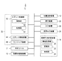
医療行為支援装置の制御系を説明するブロック図である。
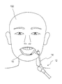
位置追跡装置を例示する説明図である。
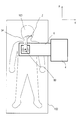
医療行為支援装置の配置位置を例示する説明図である。
医療行為支援処理の処理手順を説明するフローチャートである。
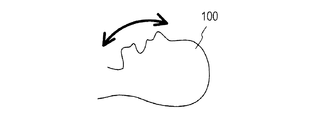
施術位置の可動範囲を上面視した図である。
X-Z平面における施術位置の可動範囲を示した図である。
施術位置のX軸に沿った可動範囲を示した図である。
以下に本開示の実施形態を図面と共に説明する。
<医療行為支援システム>
図1に示す医療行為支援システム1は、医療行為を支援するシステムである。本実施形態における医療行為支援システム1は、医療行為支援装置の一例である。
<医療行為支援システム>
図1に示す医療行為支援システム1は、医療行為を支援するシステムである。本実施形態における医療行為支援システム1は、医療行為支援装置の一例である。
本実施形態においては、医療行為として、歯科インプラントを想定する。歯科インプラントは、患者100(図3参照)の顎骨にインプラント体を埋め込み、その埋め込まれたインプラント体に補綴物を装着する歯科手術である。以下では、インプラント体を埋入する患者100の顎骨の位置(部位)を施術位置と称す。
図1,図2に示すように、医療行為支援システム1は、手術ツール2と、設置台4と、位置追跡装置12と、医療行為計画装置18と、表示装置26と、音声出力装置28と、入力装置30と、ガイドロボット32とを備えている。
手術ツール2は、医療行為に用いる器具である。この手術ツール2は、ガイドロボット32の先端に取り付けられる。
本実施形態における手術ツール2には、歯科医療に用いるドリルユニットを含む。このドリルユニットは、歯科医療に用いる各種のドリルビットと、そのドリルビットを駆動する駆動機構とを有している。なお、ここで言うドリルユニットには、いわゆる歯科用ハンドピースを含む。この歯科用ハンドピースには、ストレート・ギアードアングルハンドピースやコントラハンドピースと称されるものを含む。
医療行為支援システム1では、ガイドロボット32の先端に取り付けられた手術ツール2により、術者が実施する歯科インプラントを支援する。ここで言う「歯科インプラントの支援」には、インプラント体を埋入する患者100の部位である施術位置への手術ツール2の移動が含まれる。この手術ツール2の移動には、患者100の口腔内への手術ツール2の進入や、手術ツール2を交換する交換位置への移動が含まれる。
さらに、ここで言う「歯科インプラントの支援」には、手術ツール2としてのドリルによる顎骨への穿孔を含んでもよい。
設置台4は、ガイドロボット32が設置される機構である。この設置台4は、天板6と、支持部8と、設置台駆動機構10(図2参照)とを備えている。
天板6は、ガイドロボット32が固定される板状の部材である。支持部8は、天板6を水平に支持する支柱である。設置台駆動機構10は、天板6をX軸方向,Y軸方向,Z軸方向のそれぞれの方向に沿って駆動させるモータを有している。
すなわち、設置台4は、天板6に設置されたガイドロボット32を、水平面及び垂直方向に沿って自在に移動するように構成されている。
位置追跡装置12は、ガイドロボット32に規定された基準点と、施術位置との相対的な位置関係を特定する装置である。
本実施形態における位置追跡装置12は、アーム基準点から延出された多関節アームであるアーム14と、アーム14の先端に取り付けられるアタッチメント16とを有する。ここで言うアーム基準点とは、ガイドロボット32においてアーム14の延出が開始される位置である。
アタッチメント16は、患者100の患部に取り付けられる。本実施形態におけるアタッチメント16として、図3に示すように、施術位置がマーキングされたマウスピースを用いる。
すなわち、位置追跡装置12は、アタッチメント16のマーキングされた位置を施術位置として、アーム基準点からの相対位置によって特定する周知のトラッキングアームである。
医療行為計画装置18は、施術位置を特定して、その特定した施術位置への医療行為の計画を作成する装置である。この医療行為計画装置18は、情報取得部20と、記憶部22と、制御部24とを備えている。情報取得部20は、施術位置の特定に必要な情報(以下、「位置特定情報」と称す)を取得する。
本実施形態における情報取得部20は、コンピュータ断層撮影(CT:Computed Tomography)装置によって撮影した複数の断層画像を位置特定情報として取得する。
記憶部22は、データや処理プログラムを記憶する周知の記憶装置である。
制御部24は、少なくともROM,RAM,CPUを備えた周知のマイクロコンピュータを有した周知の制御装置であり、記憶部22に記憶された処理プログラムに従って処理を実行する。
なお、医療行為計画装置18の記憶部22には、「医療行為の計画」を作成する医療行為計画作成処理を制御部24が実行するための処理プログラムが格納されている。
この医療行為計画作成処理では、位置特定情報に基づく患者100の顎骨の3次元座標情報に従って、「医療行為の計画」を作成する。この「医療行為の計画」の作成は、インプラント体を埋入する施術位置の特定、インプラント体を埋入する角度の特定、インプラント体を埋入する深さの特定を、プランニング座標系において実施することを含む。なお、施術位置には、インプラント体を埋入する顎骨が上顎骨であるか下顎骨であるか、その顎骨における歯の位置を含む。「医療行為の計画」には、施術位置へ医療行為を実施する際のガイドロボット32の動作時における、患者100の口腔内への手術ツール2を進入させるタイミングや、その患者100の口腔内への手術ツール2の進入角度を含んでもよい。
なお、ここで言うプランニング座標系とは、医療行為計画装置18にて計画される「医療行為の計画」における座標系(例えば、CT画像における座標系)である。
以下、「医療行為の計画」を、医療行為必要情報と称す。なお、「医療行為の計画」を作成する方法は、周知であるため、ここでの詳しい説明は省略する。
表示装置26は、画像を表示する周知の装置(例えば、液晶ディスプレイ)である。音声出力装置28は、音声を出力する周知の装置(例えば、スピーカ)である。
また、入力装置30は、情報の入力を受け付ける周知の装置である。この入力装置30には、キーボードやポインティングデバイス、スイッチなどの各種入力機器を含む。ここで言うポインティングデバイスには、タッチパッドやタッチパネルなどの周知の機構を含む。
<ガイドロボット>
ガイドロボット32は、多関節アーム34と、ロボット制御部50とを備えた、周知の垂直多関節ロボットである。
<ガイドロボット>
ガイドロボット32は、多関節アーム34と、ロボット制御部50とを備えた、周知の垂直多関節ロボットである。
多関節アーム34は、設置台4に固定されるベース部36と、ベース部36から延出するアームを形成する上腕部38及び前腕部40と、前腕部40の先端に位置し、手術ツール2が取り付けられるハンド取付部42とを備えている。
多関節アーム34を構成するベース部36と上腕部38と前腕部40とハンド取付部42とは、それぞれ、関節部を介して接続されている。この関節部それぞれは、ロボット駆動装置44と、センシング装置46とを備えている。
ロボット駆動装置44は、多関節アーム34を駆動する装置である。このロボット駆動装置44として、各関節部を駆動するモータを用いる。センシング装置46は、多関節アーム34の先端(ひいては、手術ツール2)の座標を検出するものである。このセンシング装置46として、例えば、ロボット駆動装置44それぞれの回転角度を検出するロータリーエンコーダを用いてもよい。
すなわち、多関節アーム34は、実空間の三次元座標系(X,Y,Z座標系)において、複数の可動部を有する周知のアームである。この多関節アーム34の先端(即ち、ハンド取付部42)には、手術ツール2が取り付けられる。
ロボット制御部50は、センシング装置46でのセンシングの結果に従って、ガイドロボット32のロボット駆動装置44を駆動する。このロボット制御部50は、制御部52と、記憶部54とを備えている。
制御部52は、少なくともROM,RAM,CPUを備えた周知のマイクロコンピュータを有した周知の制御装置である。記憶部54は、情報やデータを記憶する周知の装置である。
記憶部54には、術者が実施する医療行為を医療行為支援システム1にて支援する医療行為支援処理をロボット制御部50が実行するための処理プログラムが格納されている。
<医療行為支援処理>
次に、ロボット制御部50が実行する医療行為支援処理について説明する。
<医療行為支援処理>
次に、ロボット制御部50が実行する医療行為支援処理について説明する。
医療行為支援処理は、図4に示すような予め規定された装置設置場所80に医療行為支援システム1を設置し、位置追跡装置12にて患者100の施術位置を追跡可能な状態とした上で起動される。なお、装置設置場所80の一例として、ベッド(手術台)102に横たわる患者100の胸部の少なくとも一部分を、設置台4の天板6が覆う位置が考えられる。
そして、医療行為支援処理が起動されると、ロボット制御部50の制御部52は、図5に示すように、医療行為計画装置18から医療行為必要情報を取得する(S110)。
そして、医療行為支援処理では、制御部52は、位置追跡装置12のアタッチメント16におけるマーキングされた箇所のアーム基準点からの相対位置を位置追跡装置12から取得する(S120)。続いて、医療行為支援処理では、制御部52は、S120で取得したアタッチメント16のマーキングされた箇所の相対位置に基づいて、実空間の3次元座標系における患者100の施術位置の初期位置を登録する(S130)。このS130における施術位置の初期位置の登録は、周知のレジストレーションに従って実行すればよい。レジストレーションは、医療行為計画装置18にて特定した、プランニング座標系における施術位置を、実空間の3次元座標系における施術位置へと変換して登録する処理である。
レジストレーションでは、具体的には、下記(1)式に従って、プランニング座標系におけるアタッチメント16のマーキングされた箇所の座標TRAKTCTを算出する。

そして、レジストレーションでは、下記(2)式に従って、実空間の3次元座標系におけるアタッチメント16のマーキングされた箇所の座標、即ち、施術位置の初期位置TRAKTIMPを算出する。

このレジストレーションにより、位置追跡装置12にて求めた、アタッチメント16におけるマーキングされた箇所のアーム基準点からの相対位置を、実空間の3次元座標系における施術位置として追尾可能となる。
なお、本実施形態においては、キャリブレーションは実行されているものとして説明する。ここで言うキャリブレーションは、ツール先端位置と施術位置との相対的な位置関係を共通する座標系に配置する処理である。ここで言う共通する座標系とは、実空間の3次元座標系であり、例えば、ガイドロボット32におけるロボット座標系である。
また、ここで言うツール先端位置とは、手術ツール2の先端部分を表す先端位置であり、例えば、ドリルビットの先端部分の位置である。
続いて、医療行為支援処理では、制御部52は、位置可動範囲を設定する(S140)。ここで言う位置可動範囲とは、施術位置が移動する可能性のある実空間上での範囲を表す。
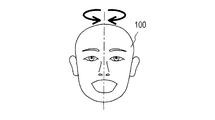
すなわち、図6A,図6B,図6Cに示すように、ベッド102に横たわっていても、患者100の頭部は、前後・左右・上下方向に可動する。この頭部の可動に伴って、実空間上の施術位置が移動するため、施術位置が移動する範囲として想定される実空間上に固定された範囲を位置可動範囲として設定する。
さらに、医療行為支援処理では、ロボット制御部50の制御部52は、S140で設定された位置可動範囲を表示装置26へと出力する(S150)。その表示装置26は、位置可動範囲を表示する。
さらに、医療行為支援処理では、制御部52は、位置可動範囲の変更指示を、入力装置30を介して受け付けたか否かを判定する(S160)。なお、位置可動範囲の変更指示は、表示装置26に表示された位置可動範囲を、入力装置30を介して修正することで受け付けてもよい。
このS160での判定の結果、位置可動範囲の変更指示を受け付けていれば(S160:YES)、制御部52は、その受け付けた変更指示に従って、位置可動範囲を変更する(S170)。なお、ここで言う位置可動範囲の変更とは、例えば、位置可動範囲を設定すべき位置を変更することや、位置可動範囲の大きさを更新することである。
その後、制御部52は、医療行為支援処理をS150へと戻す。そのS150では、制御部52は、変更された位置可動範囲を表示装置26に表示させる。
一方、S160での判定の結果、位置可動範囲の変更指示を受け付けていなければ(S160:NO)、制御部52は、医療行為支援処理をS180へと移行させる。そのS180では、制御部52は、位置追跡装置12にて求めた、アタッチメント16におけるマーキングされた箇所のアーム基準点からの相対位置に基づいて、実空間の3次元座標系における施術位置を特定する。つまり、医療行為支援処理において繰り返し実行されるS180では、施術位置を時間軸に沿って順次特定する。
続いて医療行為支援処理では、制御部52は、実空間上の施術位置へと手術ツール2が移動するようにガイドロボット32を動作させる(S190)。
さらに、医療行為支援処理では、制御部52は、S180で時間軸に沿って順次特定した施術位置に基づいて、時間軸に沿って施術位置(即ち、施術位置の推移)が変化したか否かを判定する(S200)。そして、S200での判定の結果、施術位置が時間軸に沿って変化していなければ(S200:NO)、制御部52は、詳しくは後述するS230へと医療行為支援処理を移行させる。
一方、S200での判定の結果、施術位置が時間軸に沿って変化していれば(S200:YES)、制御部52は、医療行為支援処理をS210へと移行させる。そのS210では、制御部52は、時間軸に沿った施術位置の変位に基づく施術位置の変化の状態を表す変化状態を導出する。
ここで言う変化状態とは、施術位置の変化の状態を表すものである。この変化状態には、例えば、実空間における施術位置そのものや、施術位置の揺らぎ、施術位置の加速度を含む。
なお、施術位置の揺らぎは、施術位置の平均位置からの変化量である。この施術位置の揺らぎには、例えば、二乗平均揺らぎ(即ち、分散)を含む。なお、揺らぎは、周知の手法によって算出すればよい。
また、施術位置の加速度は、施術位置を表すアタッチメント16の単位時間当たりの速度の変化率である。加速度を算出する手法は、周知であるため、ここでの詳しい説明は省略する。
さらに、医療行為支援処理では、制御部52は、変化状態が異常状態であるか否かを判定する(S220)。ここで言う異常状態とは、施術位置の状態が異常を表すものとして予め規定されたものである。
なお、実空間における施術位置そのものを変化状態とした場合には、異常状態の一例を位置可動範囲の外とすることが考えられる。また、施術位置の揺らぎを変化状態とした場合には、異常状態の一例を予め規定された第1閾値とすることが考えられる。ここで言う第1閾値は、施術位置の揺らぎが異常であることを表す値として予め規定されたものである。
さらに、施術位置の加速度を変化状態とした場合には、異常状態の一例を予め規定された第2閾値とすることが考えられる。ここで言う第2閾値は、施術位置の加速度が異常であることを表す値として予め規定されたものである。
そして、S220においては、実空間における施術位置そのものが位置可動範囲の外に存在していれば、変化状態が異常状態であるものと判定してもよい。また、S220においては、施術位置の揺らぎが第1閾値以上であれば、変化状態が異常状態であるものと判定してもよい。さらに、S220においては、施術位置の加速度が第2閾値以上であれば、変化状態が異常状態であるものと判定してもよい。
このS220での判定の結果、変化状態が異常状態であれば(S220:YES)、制御部52は、詳しくは後述するS260へと医療行為支援処理を移行させる。一方、S220での判定の結果、変化状態が異常状態でなければ(S220:NO)、制御部52は、医療行為支援処理をS230へと移行させる。
なお、S230へは、S200での判定の結果、施術位置が時間軸に沿って変化していない場合(S200:NO)にも移行される。
そのS230では、制御部52は、ツール先端位置を特定する。このツール先端位置を特定する方法として、例えば、多関節アーム34のアーム基準点との相対的な位置関係に従って特定する周知の方法が考えられる。
続いて、制御部52は、S230で特定したツール先端位置と施術位置とが一致しているか否かを判定する(S240)。そして、S240での判定の結果、ツール先端位置と施術位置とが不一致であれば(S240:NO)、制御部52は、医療行為支援処理をS180へと戻す。
一方、S240での判定の結果、ツール先端位置と施術位置とが一致していれば(S240:YES)、制御部52は、ドリルを駆動する指令であるドリル指令の入力を受け付ける(S250)。ドリル指令が入力された制御部52は、手術ツール2のドリルビットを回動させる。そして、術者は、手術ツール2を用いて顎骨への穿孔を実施する。
その後、制御部52は、医療行為支援処理をS180へと戻す。
ところで、S200での判定の結果、変化状態が異常状態である場合に移行するS260では、制御部52は、医療行為の安全性を向上させる安全制御を実行する。
安全制御の一例として、多関節アーム34の先端部分、ひいては、手術ツール2の移動を停止するようにガイドロボット32の動作を停止することが考えられる。
また、安全制御の他の例として、アタッチメント16が移動可能範囲外に存在すること、即ち、アタッチメント16が患者100の患部から外れていることを報知することが考えられる。ここで言う報知では、制御部52は、アタッチメント16が移動可能範囲外に存在する旨を示す信号を、表示装置26及び音声出力装置28に出力することが考えられる。この場合、信号を取得した表示装置26は、アタッチメント16が移動可能範囲外に存在する旨を表示し、信号を取得した音声出力装置28は、アタッチメント16が移動可能範囲外に存在する旨を音声にて出力すればよい。
その後、制御部52は、本医療行為支援処理を終了する。
[実施形態の効果]
以上説明したように、医療行為支援処理によれば、変化状態が異常状態であれば、安全制御を実行できる。その安全制御は、医療行為の安全性を向上させる制御である。
[実施形態の効果]
以上説明したように、医療行為支援処理によれば、変化状態が異常状態であれば、安全制御を実行できる。その安全制御は、医療行為の安全性を向上させる制御である。
このため、医療行為支援処理によれば、施術位置の変化が異常状態である場合であっても、医療行為における安全性を担保できる。
そして、医療行為支援処理においては、アタッチメント16が移動可能範囲外に存在することを報知している。このため、医療行為支援システム1の利用者は、施術位置の状態が異常状態であることを認識できる。
特に、医療行為支援処理においては、安全制御として、多関節アーム34の先端部分の移動を停止することを実行している。このため、医療行為支援処理によれば、変化状態が異常状態であったとしても、医療行為における安全性をより確実に担保できる。
また、医療行為支援処理では、変化状態が異常状態であるものと判定する条件の1つを、施術位置が位置可動範囲の外である場合としている。このため、医療行為支援処理においては、位置追跡装置12のアタッチメント16が患者100の患部から外れた場合に、施術位置が位置可動範囲の外であるものとして安全制御を実行でき、医療行為における安全性をより向上させることができる。
また、医療行為支援処理では、変化状態が異常状態であるものと判定する条件の1つを、施術位置の揺らぎが第1閾値以上である場合や、施術位置の加速度が第2閾値以上である場合としている。このため、医療行為支援処理においては、患者100の体動が大きい場合に、施術位置が位置可動範囲の外であることを表しているものとして安全制御を実行でき、医療行為における安全性をより向上させることができる。
なお、医療行為支援処理では、医療行為支援システム1の利用者が移動可能範囲を編集できる。このため、医療行為支援システム1の利用者は、医療行為を実施する際に使い勝手の良い移動可能範囲を設定でき、医療行為をよりスムーズに実行できる。
[その他の実施形態]
以上、本開示の実施形態について説明したが、本開示は上記実施形態に限定されるものではなく、本開示の要旨を逸脱しない範囲において、様々な態様にて実施することが可能である。
[その他の実施形態]
以上、本開示の実施形態について説明したが、本開示は上記実施形態に限定されるものではなく、本開示の要旨を逸脱しない範囲において、様々な態様にて実施することが可能である。
上記実施形態においては、位置追跡装置12を周知のトラッキングアームによって構成していたが、位置追跡装置12は、これに限るものではない。すなわち、位置追跡装置12は、例えば、指向性を高めた赤外線などの探査波を照射し、施術位置の変化を追跡する装置であってもよいし、その他の方法によって施術位置を特定可能な装置であってもよい。前者の場合、探査波を照射する機構は、医療行為支援システム1が配置される空間上に配置されてもよいし、患者100の患部に配置されてもよい。
換言すると、位置追跡装置12は、ガイドロボット32に規定された基準点と、施術位置との相対的な位置関係を特定可能な装置であれば、どのようなものであってもよい。
さらに、上記実施形態における医療行為計画装置18の情報取得部20は、コンピュータ断層撮影装置から位置特定情報を取得していたが、医療行為計画装置18の情報取得部20は、その他の装置から位置特定情報を取得してもよい。
上記実施形態においては、医療行為支援システム1が支援する医療行為として、歯科インプラントを想定していたが、医療行為支援システム1が支援する医療行為は、歯科インプラントに限るものではない。例えば、医療行為支援システムが支援する医療行為は、外科手術であってもよいし、内科医療であってもよいし、歯科インプラント以外の歯科医療であってもよいし、その他の医療行為であってもよい。
そして、施術位置は、インプラント体を埋入する患者の顎骨の位置(部位)に限るものではなく、例えば、外科手術が必要な患者100の部位や、内科医療が必要な患者100の部位、歯科医療が必要な患者100の部位であってもよい。
なお、これらの場合、ガイドロボット32の先端に取り付けられる手術ツール2は、歯科医療に用いるドリルユニットに限るものではなく、各種の医療行為に用いられる道具であってもよい。この場合の各種医療行為に用いられる道具は、例えば、メスや鉗子などの手術器具であってもよいし、その他の医療器具であってもよい。
さらに言えば、医療行為支援システム1は、ガイドロボット32による医療行為の支援を停止する停止スイッチや、ガイドロボット32による医療行為の支援の可否を受け付けるスイッチを備えていてもよい。
ここで、この出願に記載されるフローチャート、あるいは、フローチャートの処理は、複数のセクション(あるいはステップと言及される)から構成され、各セクションは、例えば、S100と表現される。さらに、各セクションは、複数のサブセクションに分割されることができる、一方、複数のセクションが合わさって一つのセクションにすることも可能である。さらに、このように構成される各セクションは、デバイス、モジュール、ミーンズとして言及されることができる。
本開示は、実施形態に準拠して記述されたが、本開示は当該実施形態や構造に限定されるものではないと理解される。本開示は、様々な変形例や均等範囲内の変形をも包含する。加えて、様々な組み合わせや形態、さらには、それらに一要素のみ、それ以上、あるいはそれ以下、を含む他の組み合わせや形態をも、本開示の範疇や思想範囲に入るものである。
Claims (7)
- 複数のアームが関節によって接続された多関節アーム(34)を有した多関節ロボット(32)と、
医療行為を受ける患者の部位の実空間上での位置を表す施術位置を特定する位置特定部(50,S180)と、
前記位置特定部で特定した施術位置の変位に基づく前記施術位置の状態が、異常を表すものとして予め規定された異常状態であるか否かを判定する異常判定部(50,S200~S220)と、
前記異常判定部での判定の結果、前記施術位置の状態が前記異常状態であれば、前記医療行為の安全性を向上させる安全制御を実行する制御部(50,S260)と
を備える、医療行為支援装置。 - 前記施術位置が移動する可能性のある空間上での範囲を表す位置可動範囲を設定する範囲設定部(50,S140)を備え、
前記異常判定部は、
前記位置特定部で特定された施術位置を前記施術位置の状態とし、前記施術位置が、前記範囲設定部で設定された位置可動範囲の外であれば、前記施術位置の状態が異常状態であるものと判定する、請求項1に記載の医療行為支援装置。 - 前記範囲設定部で設定された前記位置可動範囲の変更を受け付ける受付部(50,S160)と、
前記受付部で受け付けた前記位置可動範囲の変更に従って、前記範囲設定部で設定した位置可動範囲を更新する更新部(50,S170)と
を備え、
前記範囲設定部は、
前記更新部によって更新された位置可動範囲を、新たな位置可動範囲として設定する、請求項2に記載の医療行為支援装置。 - 前記位置特定部は、前記施術位置を時間軸に沿って繰り返し特定し、
前記判定部は、
前記位置特定部で特定された前記施術位置の推移に従って、前記施術位置の揺らぎを前記施術位置の状態として特定し、その特定した施術位置の揺らぎが、予め規定された第1閾値以上であれば、前記施術位置の状態が前記異常状態であるものと判定する
請求項1から請求項3までのいずれか一項に記載の医療行為支援装置。 - 前記位置特定部は、前記施術位置を時間軸に沿って繰り返し特定し、
前記判定部は、
前記位置特定部で特定された前記施術位置の推移に従って、前記施術位置の加速度を前記施術位置の状態として特定し、その特定した施術位置の加速度が、予め規定された第2閾値以上であれば、前記施術位置の状態が前記異常状態であるものと判定する
請求項1から請求項4までのいずれか一項に記載の医療行為支援装置。 - 前記制御部は、
前記施術位置の状態が前記異常状態であることを報知することを、前記安全制御として実行する
請求項1から請求項5までのいずれか一項に記載の医療行為支援装置。 - 前記制御部は、
前記多関節アームの先端部分の移動を停止することを、前記安全制御として実行する
請求項1から請求項6までのいずれか一項に記載の医療行為支援装置。
Priority Applications (1)
| Application Number | Priority Date | Filing Date | Title |
|---|---|---|---|
| US15/740,120 US20180185103A1 (en) | 2015-07-21 | 2016-06-09 | Medical treatment assisting apparatus |
Applications Claiming Priority (2)
| Application Number | Priority Date | Filing Date | Title |
|---|---|---|---|
| JP2015-144037 | 2015-07-21 | ||
| JP2015144037A JP2017023339A (ja) | 2015-07-21 | 2015-07-21 | 医療行為支援装置 |
Publications (1)
| Publication Number | Publication Date |
|---|---|
| WO2017013828A1 true WO2017013828A1 (ja) | 2017-01-26 |
Family
ID=57834874
Family Applications (1)
| Application Number | Title | Priority Date | Filing Date |
|---|---|---|---|
| PCT/JP2016/002791 Ceased WO2017013828A1 (ja) | 2015-07-21 | 2016-06-09 | 医療行為支援装置 |
Country Status (3)
| Country | Link |
|---|---|
| US (1) | US20180185103A1 (ja) |
| JP (1) | JP2017023339A (ja) |
| WO (1) | WO2017013828A1 (ja) |
Cited By (2)
| Publication number | Priority date | Publication date | Assignee | Title |
|---|---|---|---|---|
| WO2018116582A1 (ja) * | 2016-12-20 | 2018-06-28 | ソニー株式会社 | 制御装置、制御方法、及び医療用観察システム |
| WO2022141138A1 (zh) * | 2020-12-30 | 2022-07-07 | 诺创智能医疗科技(杭州)有限公司 | 混联主从映射方法、机械臂系统和计算机设备 |
Families Citing this family (12)
| Publication number | Priority date | Publication date | Assignee | Title |
|---|---|---|---|---|
| JP7481114B2 (ja) * | 2016-11-11 | 2024-05-10 | インテュイティブ サージカル オペレーションズ, インコーポレイテッド | 走査ベースの位置付けを伴う遠隔操作手術システム |
| JP6915869B2 (ja) | 2017-11-27 | 2021-08-04 | ソニア・セラピューティクス株式会社 | 制御装置 |
| MX2020011894A (es) * | 2018-05-10 | 2021-03-29 | Cyberdontics Usa Inc | Taladro dental automatizado. |
| EP4132414B8 (en) | 2020-04-07 | 2025-07-30 | Neocis Inc. | Splint device for guided surgical robot |
| CN111772852B (zh) | 2020-07-17 | 2025-07-22 | 雅客智慧(北京)科技有限公司 | 一种牙科机器人及口腔导航方法 |
| EP4314701A4 (en) * | 2021-03-30 | 2025-02-26 | Perceptive Technologies, Inc. | OPTICAL COHERENCE TOMOGRAPHY FOR INTRAORAL SCANNING |
| JP7316321B2 (ja) * | 2021-06-15 | 2023-07-27 | 川崎重工業株式会社 | 手術支援ロボットおよび手術支援ロボットの作動方法 |
| CN113400325B (zh) * | 2021-06-23 | 2022-03-25 | 四川锋准机器人科技有限公司 | 一种种植牙机器人导航定位方法 |
| TWI832536B (zh) | 2021-11-08 | 2024-02-11 | 美商尼奧西斯股份有限公司 | 機器人系統及操作與製造機器人系統相關方法 |
| CN113787524B (zh) * | 2021-11-18 | 2022-02-15 | 极限人工智能有限公司 | 一种机械臂的控制方法、装置、手术机器人及存储介质 |
| CN114601580B (zh) * | 2022-03-21 | 2023-07-21 | 西安交通大学口腔医院 | 基于人工智能的口腔科用高效精准牙齿种植机械臂 |
| CN121057559A (zh) * | 2023-05-04 | 2025-12-02 | 洞察科技公司 | 机器人牙科系统和为机器人牙科手术做准备的方法 |
Citations (2)
| Publication number | Priority date | Publication date | Assignee | Title |
|---|---|---|---|---|
| JP2009233240A (ja) * | 2008-03-28 | 2009-10-15 | Univ Waseda | 手術支援システム、接近状態検出装置及びそのプログラム |
| JP2013236749A (ja) * | 2012-05-15 | 2013-11-28 | Denso Corp | 歯科インプラント手術支援装置 |
Family Cites Families (2)
| Publication number | Priority date | Publication date | Assignee | Title |
|---|---|---|---|---|
| JP4212128B2 (ja) * | 1997-07-02 | 2009-01-21 | 株式会社東芝 | 放射線治療装置 |
| JP4264543B2 (ja) * | 2003-12-24 | 2009-05-20 | アロカ株式会社 | 放射線治療システム |
-
2015
- 2015-07-21 JP JP2015144037A patent/JP2017023339A/ja active Pending
-
2016
- 2016-06-09 US US15/740,120 patent/US20180185103A1/en not_active Abandoned
- 2016-06-09 WO PCT/JP2016/002791 patent/WO2017013828A1/ja not_active Ceased
Patent Citations (2)
| Publication number | Priority date | Publication date | Assignee | Title |
|---|---|---|---|---|
| JP2009233240A (ja) * | 2008-03-28 | 2009-10-15 | Univ Waseda | 手術支援システム、接近状態検出装置及びそのプログラム |
| JP2013236749A (ja) * | 2012-05-15 | 2013-11-28 | Denso Corp | 歯科インプラント手術支援装置 |
Cited By (3)
| Publication number | Priority date | Publication date | Assignee | Title |
|---|---|---|---|---|
| WO2018116582A1 (ja) * | 2016-12-20 | 2018-06-28 | ソニー株式会社 | 制御装置、制御方法、及び医療用観察システム |
| WO2022141138A1 (zh) * | 2020-12-30 | 2022-07-07 | 诺创智能医疗科技(杭州)有限公司 | 混联主从映射方法、机械臂系统和计算机设备 |
| US12528179B2 (en) | 2020-12-30 | 2026-01-20 | Noahtron Intelligence Medtech (Hangzhou) Co., Ltd. | Hybrid master-slave mapping method, robotic arm system, and computer device |
Also Published As
| Publication number | Publication date |
|---|---|
| JP2017023339A (ja) | 2017-02-02 |
| US20180185103A1 (en) | 2018-07-05 |
Similar Documents
| Publication | Publication Date | Title |
|---|---|---|
| WO2017013828A1 (ja) | 医療行為支援装置 | |
| Qiao et al. | Accuracy and safety of a haptic operated and machine vision controlled collaborative robot for dental implant placement: A translational study | |
| Liu et al. | The evolution of robotics: research and application progress of dental implant robotic systems | |
| Cheng et al. | Accuracy of dental implant surgery with robotic position feedback and registration algorithm: An in-vitro study | |
| US20250213336A1 (en) | Methods for conducting guided oral and maxillofacial procedures, and associated system | |
| US9675419B2 (en) | System and method for automating medical procedures | |
| EP3673861B1 (en) | Guided dental implantation system | |
| EP3711704B1 (en) | Surgical robot system for integrated surgical planning | |
| EP3247306B1 (en) | Interactive guidance and manipulation detection arrangements for a surgical robotic system | |
| JP6350413B2 (ja) | 医療行為支援装置 | |
| WO2016194325A1 (ja) | 医療行為支援システム | |
| WO2015107520A1 (en) | Dental guiding system and method | |
| Talib et al. | Flapless dental implant placement using a recently developed haptic robotic system | |
| Brief et al. | Robot assisted dental implantology | |
| JP2017104231A (ja) | 医療支援装置,及び多関節アームの制御方法 | |
| JP2017047005A (ja) | 医療支援装置 | |
| KR200487320Y1 (ko) | 틸팅 가능한 헤드부를 구비한 수술 내비게이션 시스템 | |
| JP6497299B2 (ja) | 医療支援装置 | |
| Malik et al. | Robotics in Oral and Maxillofacial Surgery and Implantology | |
| Vasudevan et al. | Al-Enhanced Surgical Guides for Real-Time Navigation in Dental Implant Placement Procedures | |
| HK40032762A (en) | Guided dental implantation system | |
| HK40032762B (en) | Guided dental implantation system | |
| WO2025210513A1 (en) | System for determining as-implanted parameters of an anchor portion of a dental implant | |
| Chow | Robotics in Dental | |
| CN121057558A (zh) | 患者配准的系统和方法 |
Legal Events
| Date | Code | Title | Description |
|---|---|---|---|
| 121 | Ep: the epo has been informed by wipo that ep was designated in this application |
Ref document number: 16827397 Country of ref document: EP Kind code of ref document: A1 |
|
| NENP | Non-entry into the national phase |
Ref country code: DE |
|
| 122 | Ep: pct application non-entry in european phase |
Ref document number: 16827397 Country of ref document: EP Kind code of ref document: A1 |