WO2017013728A1 - 送信装置、受信装置、無線通信システム、及び、処理方法 - Google Patents
送信装置、受信装置、無線通信システム、及び、処理方法 Download PDFInfo
- Publication number
- WO2017013728A1 WO2017013728A1 PCT/JP2015/070654 JP2015070654W WO2017013728A1 WO 2017013728 A1 WO2017013728 A1 WO 2017013728A1 JP 2015070654 W JP2015070654 W JP 2015070654W WO 2017013728 A1 WO2017013728 A1 WO 2017013728A1
- Authority
- WO
- WIPO (PCT)
- Prior art keywords
- signal sequence
- relationship
- parameter
- shift amount
- signal
- Prior art date
Links
Images


Classifications
-
- H—ELECTRICITY
- H04—ELECTRIC COMMUNICATION TECHNIQUE
- H04J—MULTIPLEX COMMUNICATION
- H04J11/00—Orthogonal multiplex systems, e.g. using WALSH codes
-
- H—ELECTRICITY
- H04—ELECTRIC COMMUNICATION TECHNIQUE
- H04W—WIRELESS COMMUNICATION NETWORKS
- H04W72/00—Local resource management
- H04W72/04—Wireless resource allocation
Definitions
- the present invention relates to a transmission device, a reception device, a wireless communication system, and a processing method.
- a wireless communication system including a transmission device and a reception device that communicates wirelessly is known (for example, see Non-Patent Document 1).
- the transmission device transmits a signal sequence generated according to a predetermined method.
- the receiving apparatus performs channel estimation based on the signal sequence generated according to the above method and the received signal.
- a shift amount is determined based on identification information for identifying a period during which the second signal sequence is transmitted from a plurality of periods included in the radio frame, and the first shift amount is determined by the determined shift amount.
- a second signal sequence is generated by cyclically shifting the signal sequence.
- 3GPP TS 36.211 V12.5.0 “Technical Specification Group, Radio Access Network, Evolved Universal Terrestrial, and 15 (E-UTRA). Search on June 15, 2015], Internet ⁇ URL: http://www.3gpp.org/ftp/Specs/archive/36_series/36.211/36211-c50.zip>
- the cycle in which the second signal sequence is transmitted may be a cycle obtained by multiplying the time length of the radio frame by a natural number.
- the identification information for identifying the period in which the second signal sequence is transmitted in each of the plurality of radio frames in which the second signal sequence is transmitted is the same information. Therefore, in this case, the same signal sequence is transmitted as the second signal sequence in each of the plurality of radio frames in which the second signal sequence is transmitted. As a result, for example, a state in which the reception quality of the second signal sequence is excessively low due to the presence of an interference wave may continue.
- one of the objects of the present invention is to improve the reception quality of a signal sequence.
- the transmission device transmits a signal wirelessly. Furthermore, the transmission device includes an acquisition unit and a transmission unit. The acquisition unit acquires a frame number of a radio frame. The transmission unit transmits a second signal sequence obtained by cyclically shifting the first signal sequence by a first shift amount based on the acquired frame number in the radio frame having the acquired frame number. To do.
- the receiving device receives a signal wirelessly. Further, the receiving device includes an acquisition unit and an estimation unit.
- the acquisition unit acquires a frame number of a radio frame.
- the estimation unit performs channel estimation for the radio frame based on the second signal series and the signal received in the radio frame having the acquired frame number.
- the second signal sequence is a signal sequence obtained by cyclically shifting the first signal sequence by a first shift amount based on the acquired frame number.
- FIG. 1 It is a block diagram showing an example of composition of a radio communications system of a 1st embodiment. It is a block diagram showing an example of a structure of the terminal device of FIG. It is a table showing an example of the parameter which the terminal device of FIG. 1 uses. It is explanatory drawing showing an example of allocation of the radio resource with respect to transmission of DM-RS. It is a table showing an example of the relationship between a shift amount and the cyclically shifted symbol parameter series. It is explanatory drawing showing an example of the relationship between a symbol period number and the symbol parameter used for calculation of a signal sequence cyclic shift parameter. It is explanatory drawing showing an example of the relationship between a symbol period number and the symbol parameter used for calculation of a signal sequence cyclic shift parameter. FIG.
- FIG. 2 is a block diagram illustrating an example of a configuration of a base station apparatus in FIG. 1. It is explanatory drawing showing an example of the process which the frequency deviation estimation part of FIG. 8 performs. It is a flowchart showing an example of the process which the terminal device of FIG. 1 performs. It is a flowchart showing an example of the process which the base station apparatus of FIG. 1 performs. It is a graph showing an example of the change with respect to the sub-frame of a frequency deviation estimated value in case the symbol parameter cyclic shift is not performed. It is a graph showing an example of the change with respect to the sub-frame of a frequency deviation estimated value in case symbol symbol cyclic shift is performed.
- the wireless communication system 1 includes a plurality of base station devices 10, a plurality of terminal devices 20, and a plurality of terminal devices 30.
- the number of base station apparatuses 10 included in the wireless communication system 1 may be one.
- the number of terminal devices 20 included in the wireless communication system 1 may be one.
- the number of terminal devices 30 included in the wireless communication system 1 may be one.
- the radio communication system 1 may not include the terminal device 30.
- the wireless communication system 1 performs communication according to a predetermined communication method.
- the communication method is the LTE method.
- LTE is an abbreviation for Long Term Evolution.
- the communication method may be a method different from the LTE method (for example, a method such as LTE-Advanced).
- the base station apparatus 10 forms a cell.
- the base station apparatus 10 may form a plurality of cells.
- a cell is an example of a wireless area.
- the wireless area may be represented as a coverage area or a communication area.
- the cell is a macro cell, a micro cell, a nano cell, a pico cell, a femto cell, a home cell, a small cell, a sector cell, or the like.
- the base station device 10 communicates wirelessly with terminal devices 20 and 30 located in a cell formed by the base station device 10.
- the base station apparatus 10 provides radio resources in a cell formed by the base station apparatus 10.
- radio resources are identified by time and frequency.
- a radio resource corresponding to the time of one OFDM symbol of one subcarrier in OFDM may be represented as a resource element (RE; Resource Element).
- OFDM is an abbreviation for Orthogonal Frequency-Division Multiplexing.
- the radio resource includes a plurality of REs having different combinations of time and frequency.
- a period corresponding to seven REs that are continuous along the time axis is called a slot.
- Two slots that are continuous along the time axis form one subframe.
- 10 subframes that are continuous along the time axis form one radio frame.
- the base station apparatus 10 communicates with the terminal apparatuses 20 and 30 located in the cell formed by the base station apparatus 10 by using radio resources provided in the cell.
- the base station device 10 may be represented as a base station, an eNB (Evolved Node B), a wireless device, or a wireless communication device.
- the base station device 10 is an example of a receiving device.
- the base station apparatus 10 is connected to a communication network (for example, a core network) NW so that communication is possible.
- a communication network for example, a core network
- NW a communication network
- An interface between the base station apparatus 10 and the communication network NW may be represented as an S1 interface.
- the interface between the base station apparatuses 10 may be represented as an X2 interface.
- EPC The portion of the wireless communication system 1 that is closer to the communication network NW (that is, the upper level) than the base station device 10 may be represented as EPC.
- EPC is an abbreviation for Evolved Packet Core.
- a portion formed by the base station apparatus 10 in the wireless communication system 1 may be represented as E-UTRAN.
- E-UTRAN is an abbreviation for Evolved Universal Terrestrial Radio Access Network.
- the terminal device 20 or 30 communicates wirelessly with the base station device 10 that forms the cell, using the radio resource provided in the cell in which the terminal device 20 or 30 is located.
- the terminal device 20 or 30 may be represented as a radio terminal, a radio device, or a user terminal (UE; User Equipment).
- the terminal device 20 or 30 is an example of a transmission device.
- the terminal device 20 includes a reception antenna 201, a reception RF unit 202, a PDSCH demodulation unit 203, and a CQI calculation unit 204.
- RF is an abbreviation for Radio Frequency.
- PDSCH is an abbreviation for Physical Downlink Shared Channel.
- CQI is an abbreviation for Channel Quality Indicator.
- the terminal device 20 includes a symbol parameter generation unit 205, a switching unit 206, a symbol parameter cyclic shift unit 207, and a signal sequence cyclic shift parameter calculation unit 208.
- the terminal device 20 includes a DM-RS generation unit 209, a PUCCH generation unit 210, a PUSCH generation unit 211, a channel multiplexing unit 212, a transmission RF unit 213, and a transmission antenna 214.
- DM-RS is an abbreviation for Demodulation Reference Signal.
- PUCCH is an abbreviation for Physical Uplink Control Channel.
- PUSCH is an abbreviation for Physical Uplink Shared Channel.
- Each of PDSCH and PUSCH is an example of a communication channel used for data signal transmission.
- PUCCH is an example of a communication channel used for transmission of a control signal.
- the reception RF unit 202 executes reception RF processing for converting a radio signal received via the reception antenna 201 into a baseband signal (in other words, a BB signal).
- the reception RF processing includes conversion from a radio frequency to a base frequency (in other words, down conversion) and conversion from an analog signal to a digital signal.
- Reception RF section 202 outputs the BB signal to PDSCH demodulation section 203 and CQI calculation section 204, respectively.
- the PDSCH demodulation unit 203 performs demodulation on a signal transmitted using a radio resource allocated to the PDSCH among BB signals input from the reception RF unit 202.
- PDSCH demodulation section 203 outputs information obtained by demodulation to switching section 206, signal sequence cyclic shift parameter calculation section 208, DM-RS generation section 209, and PUCCH generation section 210.
- the information obtained by demodulation includes PUCCH resource information and setting information described later.
- the PUCCH resource information is information associated with a radio resource allocated to the PUCCH in communication between the base station apparatus 10 and the terminal apparatus 20.
- the PUCCH resource information may be expressed as a PUCCH resource index.
- the CQI calculation unit 204 calculates the CQI based on the BB signal input from the reception RF unit 202. For example, the CQI is calculated based on CSI-RS.
- CSI-RS is an abbreviation for Channel State Information Reference Signal.
- CQI is an example of information indicating the reception quality of a communication channel.
- CQI calculating section 204 outputs the calculated CQI to PUCCH generating section 210.
- symbol parameter generation unit 205 switching unit 206, symbol parameter cyclic shift unit 207, and signal sequence cyclic shift parameter calculation unit 208 will be described later.
- signal sequence cyclic shift parameter calculation section 208 calculates signal sequence cyclic shift parameter ⁇ , and transmits the calculated signal sequence cyclic shift parameter ⁇ to DM-RS generation section 209 and PUCCH generation section 210, respectively. Output.
- the DM-RS generation unit 209 generates a DM-RS based on the signal sequence cyclic shift parameter ⁇ input from the signal sequence cyclic shift parameter calculation unit 208.
- DM-RS is a reference signal used for demodulation of a control signal transmitted via PUCCH.
- DM-RS generation section 209 outputs the generated DM-RS to channel multiplexing section 212.
- the DM-RS generation unit 209 generates a signal sequence r ( ⁇ ) u, ⁇ (q) transmitted as DM-RS based on Equation 1.
- q represents each integer which is 0 or more and is smaller than M RS sc .
- M RS sc represents the number of signals included in the DM-RS.
- M RS sc signals included in the DM-RS are transmitted using M RS sc REs, respectively.
- M RS sc is equal to the number of subcarriers included in one RB.
- j represents an imaginary unit.
- r base u, ⁇ (q) is represented as a base sequence.
- the DM-RS generation unit 209 generates a base sequence r base u, ⁇ (q) based on Equation 2.
- ⁇ (q) is determined in advance in association with the parameter u, for example, as shown in FIG.
- the DM-RS generation unit 209 calculates the parameter u based on Equation 3 to Equation 5.
- the DM-RS generation unit 209 uses an identifier for identifying a cell (in other words, a cell identifier) as the parameter n RS ID .
- the cell identifier may be expressed as a cell ID.
- the DM-RS generation unit 209 acquires a cell identifier that identifies the cell in which the terminal device 20 is located. For example, the cell identifier is transmitted from the base station device 10 to the terminal device 20. The cell identifier may be acquired by the terminal device 20 based on information transmitted from the base station device 10 to the terminal device 20. Also, the DM-RS generation unit 209 may use a value set by the wireless communication system 1 as the parameter n RS ID .
- n s represents a slot number.
- the slot number is information for identifying a slot in each radio frame.
- the slot number starts from 0 and increases by 1 for each slot in the direction in which the time advances along the time axis in the radio frame.
- the DM-RS generation unit 209 initializes the pseudo-random sequence c (x) using the initialization parameter c init expressed by Equation 6.
- the initialization parameter c init may be expressed as a seed. Therefore, in this example, the pseudo-random sequence c (x) is determined based on the parameter n RS ID (in this example, a cell identifier).
- the DM-RS generation unit 209 rotates the phase of the base sequence r base u, ⁇ (q) by the signal sequence cyclic shift parameter ⁇ in the frequency domain.
- the phase rotation in the frequency domain corresponds to a cyclic shift in the time domain. Therefore, the signal sequence cyclic shift parameter ⁇ corresponds to the shift amount of the cyclic shift in the time domain.
- the base sequence r base u, ⁇ (q) is an example of a first signal sequence.
- Signal sequence r ( ⁇ ) u, ⁇ ( q) is an example of a second signal sequence.
- the signal sequence cyclic shift parameter ⁇ is an example of a first shift amount.
- the cyclic shift may be represented as a cyclic shift.
- the PUCCH generation unit 210 is a control signal transmitted via the PUCCH based on the CQI input from the CQI calculation unit 204 and the signal sequence cyclic shift parameter ⁇ input from the signal sequence cyclic shift parameter calculation unit 208. Is generated.
- a control signal transmitted via the PUCCH may be represented as a PUCCH signal.
- the PUCCH generation unit 210 generates a PUCCH signal by rotating the phase of a signal representing CQI in the frequency domain based on the signal sequence cyclic shift parameter ⁇ . Note that transmission via a communication channel may be expressed as transmission using radio resources allocated to the communication channel. PUCCH generation section 210 outputs the generated control signal to channel multiplexing section 212.
- the PUSCH generation unit 211 generates a data signal transmitted via the PUSCH based on the user data, and outputs the generated data signal to the channel multiplexing unit 212.
- the user data is information input by the user of the terminal device 20.
- the channel multiplexing unit 212 multiplexes signals input from the DM-RS generation unit 209, the PUCCH generation unit 210, and the PUSCH generation unit 211, and outputs the multiplexed signals to the transmission RF unit 213.
- signal multiplexing is performed such that the PUCCH signal and the DM-RS are transmitted in a radio frame having the frame number used for generating the PUCCH signal and the DM-RS.
- radio resources are allocated to PUCCH signals and DM-RS transmissions according to a predetermined format.
- the format may be expressed as PUCCH format 2.
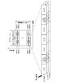
- the transmission of the PUCCH signal and DM-RS is assigned to one subframe every predetermined transmission period (in this example, a period obtained by multiplying the time length of the radio frame by a natural number). Further, for example, as shown in FIG. 4, the transmission of the PUCCH signal and the DM-RS is transmitted to RBs 901 to 908 at both ends in the direction along the frequency axis among a plurality of RBs included in the system bandwidth. Assigned.
- a DM-RS is allocated to each of two symbol periods (ST # 1 and ST # 5 in this example).
- the symbol period is a period corresponding to one RE.
- a PUCCH signal is assigned.
- the signal sequence cyclic shift parameter ⁇ is calculated based on a parameter determined for each terminal device 20.
- the plurality of signals that are respectively phase-rotated based on a plurality of different signal sequence cyclic shift parameters ⁇ are orthogonal to each other.
- the PUCCH signal and the DM-RS are received by the base station apparatus 10 as a code-multiplexed signal by being transmitted from each of the plurality of terminal apparatuses 20.
- the signals S-UE # 0 to # 2 respectively transmitted from the first to third terminal apparatuses 20 are received by the base station apparatus 10 as code-multiplexed signals. .
- the transmission of the PUCCH signal and the DM-RS is allocated to the RB associated with the PUCCH resource information n (2, p) PUCCH .
- the RB assigned to the transmission of the PUCCH signal and DM-RS is determined in advance in association with the parameter m.
- RBs associated with the same parameter m have different frequencies. In other words, frequency hopping is applied to radio resources allocated to PUCCH signals and DM-RS transmissions.
- N RB sc represents the number of subcarriers included in one RB.
- the transmission RF unit 213 executes transmission RF processing for converting the BB signal input from the channel multiplexing unit 212 into a radio signal.
- the transmission RF processing includes conversion from a digital signal to an analog signal and conversion from a base frequency to a radio frequency (in other words, up-conversion).
- the transmission RF unit 213 transmits a radio signal via the transmission antenna 214.
- the symbol parameter generation unit 205 the switching unit 206, the symbol parameter cyclic shift unit 207, and the signal sequence cyclic shift parameter calculation unit 208 will be described.
- the symbol parameter generation unit 205 acquires a cell identifier that identifies a cell in which the terminal device 20 is located. For example, the cell identifier is transmitted from the base station device 10 to the terminal device 20. The cell identifier may be acquired by the terminal device 20 based on information transmitted from the base station device 10 to the terminal device 20. The symbol parameter generation unit 205 generates a symbol parameter n cell cs (n) for each of a plurality of symbol periods included in the radio frame based on Expression 8.
- the symbol period number n represents a symbol period number.
- the symbol period number n is information for identifying a symbol period in each radio frame. In this example, the symbol period number starts from 0 and increases by 1 for each symbol period in the direction in which the time advances along the time axis in the radio frame.
- the symbol period number n is an example of identification information that identifies each of a plurality of periods included in a radio frame.
- the relationship between the symbol period number n and the symbol parameter n cell cs (n) represented by Expression 8 is an example of a third relationship.
- the symbol period number n represents each integer that is greater than or equal to 0 and smaller than N symb .
- N symb denotes (in other words, a symbol period number) number of symbol periods included in one radio frame.
- the number of symbol periods N sym is expressed by Equation 9.
- N UL symb represents the number of symbol periods included in one slot.
- N frame slot represents the number of slots included in one radio frame. In this example, the number of symbol periods N sym is 140.
- a plurality of respective symbols parameter n cell cs generated for symbol period included in the radio frame (0), ..., n cell cs (N symb -1) may be represented as symbol parameter sequence n cell cs .
- the symbol parameter generation unit 205 initializes the pseudo-random sequence c (x) based on the acquired cell identifier and Equation 6, as with the DM-RS generation unit 209. Therefore, in this example, the symbol parameter n cell cs (n) is determined based on the cell identifier that identifies the cell in which the terminal device 20 is located. Note that the symbol parameter generation unit 205 may share the pseudo-random sequence c (x) with the DM-RS generation unit 209.
- the symbol period number n may be expressed by Equation 10.
- l represents a symbol number.
- the symbol number is information for identifying a symbol period in each slot. In this example, the symbol number starts from 0 and increases by 1 for each symbol period in the direction in which the time advances along the time axis in the slot.
- Symbol parameter generating unit 205 outputs the generated symbol parameter sequence n cell cs to the switching unit 206. Based on the input setting information, the switching unit 206 transfers the symbol parameter sequence n cell cs input from the symbol parameter generation unit 205 to one of the symbol parameter cyclic shift unit 207 and the signal sequence cyclic shift parameter calculation unit 208. Is output.
- the setting information represents whether or not to perform symbol parameter cyclic shift described later.
- the setting information may be transmitted from the base station device 10 to the terminal device 20.
- the switching unit 206 outputs the symbol parameter sequence n cell cs to the symbol parameter cyclic shift unit 207 when the setting information indicates that the symbol parameter cyclic shift is executed.
- switching section 206 outputs symbol parameter sequence n cell cs to signal sequence cyclic shift parameter calculation section 208.
- the symbol parameter cyclic shift unit 207 acquires the frame number of the radio frame.
- the frame number may be expressed as SFN (System Frame Number).
- SFN System Frame Number
- the frame number is transmitted from the base station device 10 to the terminal device 20.
- the frame number may be acquired by the terminal device 20 based on information transmitted from the base station device 10 to the terminal device 20.
- the symbol parameter cyclic shift unit 207 is an example of an acquisition unit.
- the symbol parameter cyclic shift unit 207 cyclically shifts the symbol parameter series n cell cs input from the switching unit 206 by the shift amount ⁇ SFN (i) based on the acquired frame number i.
- i represents each integer from 0 to a predetermined maximum number.
- the maximum number is 1023, for example.
- the shift amount may be regarded as ⁇ SFN (i) mod N symb .
- the remainder calculated by the operator mod is a positive number.
- the cyclic shift of the symbol parameter series n cell cs may be expressed as a symbol parameter cyclic shift.
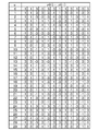
- the relationship between the shift amount ⁇ SFN (i) and the cyclically shifted symbol parameter sequence n ′ cell cs is expressed as shown in FIG.
- the symbol parameter cyclic shift unit 207 calculates the shift amount ⁇ SFN (i) based on Equation 12.
- the shift amount ⁇ SFN (i) is determined based on the relationship between the symbol period number n and the symbol parameter n cell cs (n) represented by Expression 8 and the acquired frame number i. Is done.
- the shift amount ⁇ SFN (i) is an example of a second shift amount.
- Symbol parameter cyclic shift section 207 outputs the cyclically shifted symbol parameter series n ′ cell cs to signal series cyclic shift parameter calculation section 208.
- the signal sequence cyclic shift parameter calculation unit 208 calculates a signal sequence cyclic shift parameter ⁇ (n).
- the signal sequence cyclic shift parameter ⁇ (n) is calculated based on the symbol parameter sequence n cell cs input from the switching unit 206 or the symbol parameter sequence n ′ cell cs input from the symbol parameter cyclic shift unit 207. It is.
- the signal sequence cyclic shift parameter calculation unit 208 calculates the signal sequence cyclic shift parameter ⁇ (n) based on Equation 13.
- the signal sequence cyclic shift parameter calculation unit 208 calculates the parameter n (p) cs (n) based on Equation 14.
- n ′ p (n s ) is a parameter determined based on the PUCCH resource information. Accordingly, the parameter n ′ p (n s ) is determined for each terminal device 20.
- the relationship between the symbol parameter n cell cs (n) and the signal sequence cyclic shift parameter ⁇ (n) represented by Equation 13 and Equation 14 is an example of a fourth relationship. Further, the relationship between the symbol period number n and the signal sequence cyclic shift parameter ⁇ (n) represented by Equation 8, Equation 13, and Equation 14 is an example of a first relationship.
- the signal sequence cyclic shift parameter calculation unit 208 calculates the parameter n (p) cs (n) based on Equation 15.
- the relationship between the symbol period number n and the signal sequence cyclic shift parameter ⁇ (n) expressed by Equation 8, Equation 11 to Equation 13, and Equation 15 is an example of a second relationship.
- the signal sequence cyclic shift parameter calculation unit 208 outputs the calculated signal sequence cyclic shift parameter ⁇ (n) to the DM-RS generation unit 209 and the PUCCH generation unit 210, respectively.
- the DM-RS generation unit 209 includes a signal sequence cyclic shift parameter ⁇ (n) associated with a symbol period allocated to transmission of a DM-RS to be generated, of the input signal sequence cyclic shift parameter ⁇ (n). ) To generate the DM-RS.
- the PUCCH generation unit 210 is based on a signal sequence cyclic shift parameter ⁇ (n) associated with a symbol period allocated to transmission of a PUCCH signal scheduled to be generated among the input signal sequence cyclic shift parameters ⁇ (n). To generate the PUCCH signal.
- the DM-RS generated based on the signal sequence cyclic shift parameter ⁇ (n) calculated based on Expression 14 is an example of a signal sequence that is cyclically shifted without being based on the frame number.
- the DM-RS generated based on the signal sequence cyclic shift parameter ⁇ (n) calculated based on Equation 15 is an example of a signal sequence that is cyclically shifted based on the frame number.
- the symbol parameter n cell cs (n) generated by the symbol parameter generation unit 205 is used to calculate the signal sequence cyclic shift parameter ⁇ (n) for the symbol period number n. It is done.
- each terminal apparatus 20 calculates the signal sequence cyclic shift parameter ⁇ (n) using the symbol parameter n cell cs (n) common between radio frames for the same symbol period number n.
- the setting information represents performing symbol parameter cyclic shift
- the calculation of the signal sequence cyclic shift parameters for symbol period number n ⁇ (n) the symbol parameter was allowed to cyclic shift by the signal sequence cyclic shift parameter calculating unit 208 n 'cell cs (n) is used.
- the symbol parameter n ′ cell cs (n) used to calculate the signal sequence cyclic shift parameter ⁇ (n) is the symbol parameter n cell cs ⁇ (n ⁇ SFN (i)) mod N symb in the radio frame with frame number i. ⁇ .
- the symbol parameter n ′ cell cs (n) used for calculating the signal sequence cyclic shift parameter ⁇ (n) is the symbol parameter n cell cs ⁇ (n ⁇ ⁇ SFN (i + 1)) mod in the radio frame with frame number i + 1. N sym ⁇ .
- the symbol parameter n ′ cell cs (n) used for calculating the signal sequence cyclic shift parameter ⁇ (n) for the symbol period number n includes the radio frame with the frame number i, the radio frame with the frame number i + 1, Vary between.
- each terminal device 20 calculates the signal sequence cyclic shift parameter ⁇ (n) using the symbol parameter n ′ cell cs (n) that differs between radio frames for the same symbol period number n.
- the shift amount ⁇ SFN (i) has different values between cells for the same frame number i, as expressed in Expression 8 and Expression 12.
- the extent to which the DM-RSs transmitted by the first and second terminal devices 20 interfere with each other is likely to change with changes in the radio frame.
- the symbol parameter cyclic shift unit 207, the signal sequence cyclic shift parameter calculation unit 208, the DM-RS generation unit 209, the channel multiplexing unit 212, the transmission RF unit 213, and the transmission antenna 214 are examples of transmission units.
- the number of reception antennas 201 included in the terminal device 20 may be two or more. Further, the number of transmission antennas 214 included in the terminal device 20 may be two or more. Further, the terminal device 20 may include a shared antenna that functions as each of the reception antenna 201 and the transmission antenna 214 instead of the reception antenna 201 and the transmission antenna 214.
- the reception RF unit 202 and the transmission RF unit 213 may be realized using an LSI (Large Scale Integration).
- the LSI may be a programmable logic circuit device (for example, PLD or FPGA).
- PLD is an abbreviation for Programmable Logic Device.
- FPGA is an abbreviation for Field-Programmable Gate Array.
- the units 203 to 212 included in the terminal device 20 may be realized using a processing device and a storage device.
- the processing device may be a CPU (Central Processing Unit) or a DSP (Digital Signal Processor).
- the terminal device 30 has the same configuration as the terminal device 20 except that the terminal device 30 does not have a function of executing symbol parameter cyclic shift.
- the base station apparatus 10 includes a PUCCH resource allocation unit 101, a PDSCH generation unit 102, a CSI-RS generation unit 103, a channel multiplexing unit 104, a transmission RF unit 105, A transmission antenna 106.
- the base station apparatus 10 includes a symbol parameter generation unit 107, a switching unit 108, a symbol parameter cyclic shift unit 109, and a signal sequence cyclic shift parameter calculation unit 110.
- the base station apparatus 10 includes a reception antenna 111, a reception RF unit 112, a channel estimation unit 114, a frequency deviation estimation unit 115, a PUCCH demodulation unit 116, and a PUSCH demodulation unit 117.
- the PUCCH resource allocation unit 101 acquires terminal information.
- the terminal information includes a terminal identifier for identifying the terminal device 20 or 30, and information indicating whether the terminal device 20 or 30 can execute the symbol parameter cyclic shift.
- the terminal information is transmitted from the terminal device 20 or 30 to the base station device 10.
- the base station apparatus 10 may receive terminal information from an apparatus different from the terminal apparatuses 20 and 30 included in the wireless communication system 1.
- the PUCCH resource allocation unit 101 determines setting information and PUCCH resource information based on the acquired terminal information.
- Setting information indicating that symbol parameter cyclic shift is executed may be determined for the terminal device 20 that can execute symbol parameter cyclic shift.
- Setting information indicating that the symbol parameter cyclic shift is not executed is determined for the terminal device 30 that cannot execute the symbol parameter cyclic shift.
- the terminal device 20 for which the setting information indicating that the symbol parameter cyclic shift is executed may be represented as an execution terminal device.
- the terminal device 20 or 30 for which setting information indicating that symbol parameter cyclic shift is not performed may be represented as a non-execution terminal device.
- the PUCCH resource allocation unit 101 determines different PUCCH resource information for the execution terminal device 20 and the non-execution terminal device 20 or 30. Thereby, the PUCCH resource allocation unit 101 allocates different radio resources to DM-RS and PUCCH signal transmission by the execution terminal device 20 and the non-execution terminal device 20 or 30, respectively.
- PUCCH resource allocation unit 101 is an example of an allocation unit.
- PUCCH resource allocation section 101 outputs the determined PUCCH resource information and setting information to PDSCH generation section 102, switching section 108, signal sequence cyclic shift parameter calculation section 110, channel estimation section 114, and PUCCH demodulation section 116, respectively. To do.
- the PDSCH generating unit 102 generates a data signal transmitted via the PDSCH based on the PUCCH resource information and setting information input from the PUCCH resource allocating unit 101 and user data, and the generated data signal is used as a channel.
- the data is output to the multiplexing unit 104.
- user data is transmitted from information transmitted from a terminal device 20 or 30 different from the terminal device 20 or 30 to which the data signal is transmitted, or from a device different from the terminal devices 20 and 30 included in the wireless communication system 1.
- Information is transmitted from information transmitted from a terminal device 20 or 30 different from the terminal device 20 or 30 to which the data signal is transmitted, or from a device different from the terminal devices 20 and 30 included in the wireless communication system 1.
- CSI-RS generating section 103 generates CSI-RS and outputs the generated CSI-RS to channel multiplexing section 104.
- Channel multiplexing section 104 multiplexes signals input from PDSCH generation section 102 and CSI-RS generation section 103 and outputs the multiplexed signals to transmission RF section 105.
- the transmission RF unit 105 executes transmission RF processing for converting the BB signal input from the channel multiplexing unit 104 into a radio signal.
- the transmission RF unit 105 transmits a radio signal via the transmission antenna 106.
- the symbol parameter generation unit 107 functions in the same manner as the symbol parameter generation unit 205 except that the cell identifier held by the base station apparatus 10 is used.
- the switching unit 108 functions in the same manner as the switching unit 206 except that the setting information input from the PUCCH resource allocation unit 101 is used.
- the symbol parameter cyclic shift unit 109 functions in the same manner as the symbol parameter cyclic shift unit 207 except that the frame number held by the base station apparatus 10 is used.
- the symbol parameter cyclic shift unit 109 is an example of an acquisition unit.
- the signal sequence cyclic shift parameter calculation unit 110 uses the signal sequence cyclic shift parameter calculation unit 208, except that the PUCCH resource information input from the PUCCH resource allocation unit 101 is used and the output destination of the parameter ⁇ (n). Works in the same way.
- Signal sequence cyclic shift parameter calculation section 110 outputs signal sequence cyclic shift parameter ⁇ (n) to channel estimation section 114 and PUCCH demodulation section 116, respectively.
- the reception RF unit 112 performs reception RF processing for converting a radio signal received via the reception antenna 111 into a BB signal.
- Reception RF section 112 outputs the BB signal to channel estimation section 114, PUCCH demodulation section 116, and PUSCH demodulation section 117.
- the PUCCH demodulation unit 116 transmits via the PUCCH based on the input PUCCH resource information, the input signal sequence cyclic shift parameter ⁇ (n), and a channel estimation value and a frequency deviation estimation value, which will be described later. Demodulate the processed signal.
- the information obtained by demodulation includes CQI.
- the PUSCH demodulation unit 117 performs demodulation on a signal transmitted via the PUSCH among BB signals input from the reception RF unit 112 based on a frequency deviation estimation value described later.
- the information obtained by demodulation includes user data.
- the channel estimation unit 114 Based on the signal sequence cyclic shift parameter ⁇ (n) input from the signal sequence cyclic shift parameter calculation unit 110, the channel estimation unit 114 performs DM-RS (in other words, a replica signal) in the same manner as the DM-RS generation unit 209. ) Is generated.
- DM-RS in other words, a replica signal
- the channel estimation unit 114 is based on the generated replica signal and the signal transmitted using the radio resource allocated to the DM-RS transmission out of the BB signal input from the reception RF unit 112. Channel estimation.
- the signal used for channel estimation is a signal received in a radio frame having the frame number used for generating the replica signal.
- channel estimation is estimation of the state of a communication channel.
- the result of channel estimation may be expressed as a channel estimate.
- Channel estimation section 114 outputs the channel estimation value to each of frequency deviation estimation section 115 and PUCCH demodulation section 116.
- the frequency deviation estimation unit 115 estimates a frequency difference (in other words, a frequency deviation) between the base station device 10 and the terminal device 20 or 30 based on the channel estimation value input from the channel estimation unit 114.
- the frequency deviation may be expressed as a frequency difference.
- the result of the frequency deviation estimation may be expressed as a frequency deviation estimated value.
- Frequency deviation estimation section 115 outputs the frequency deviation estimation value to each of PUCCH demodulation section 116 and PUSCH demodulation section 117.
- the frequency deviation estimation unit 115 performs complex conjugate processing on the channel estimation value in one of the two symbol periods for each slot.
- h a, b (f) represents the channel estimation value for the f-th RE among the REs included in the slot with the slot number a and included in the symbol period with the symbol number b.
- f represents each integer that is greater than or equal to 0 and smaller than N RB sc .
- the channel estimation value in one of the two symbol periods in slot # 0 is represented by h 0,1 (0),..., H 0,1 (11).
- the channel estimate in one of the two symbol periods in slot # 1 is represented by h 1,1 (0),..., H 1,1 (11).
- the frequency deviation estimation unit 115 performs correlation calculation processing between the channel estimation value in the other of the two symbol periods and the channel estimation value after execution of the complex conjugate processing for each slot. .
- the channel estimation value in the other of the two symbol periods in slot # 0 is represented by h 0,5 (0),..., H 0,5 (11).
- the channel estimation value in the other of the two symbol periods in slot # 1 is represented by h 1,5 (0),..., H 1,5 (11).
- the frequency deviation estimation unit 115 performs an intra-frame averaging process on the result of the correlation calculation process for each of the two consecutive slots for each subframe.
- the intraframe averaging process includes a process of averaging the results of the correlation calculation process for each of the two slots.
- the intraframe average processing may include processing for averaging the results of the correlation calculation processing among the subcarriers.
- the frequency deviation estimation unit 115 performs an inter-frame averaging process on the result of the intra-frame averaging process for each of the plurality of subframes.
- the interframe averaging process includes a process of averaging the results of the intraframe averaging process for each of the plurality of subframes.
- the average may be a forgetting average.
- the forgetting average is expressed by Equation 16.
- ⁇ represents a forgetting factor.
- the forgetting factor ⁇ represents a real number larger than 0 and smaller than 1.
- R represents the result of the intraframe averaging process for a certain subframe.
- R ave represents the result of averaging process between frames.
- the frequency deviation estimator 115 updates the inter-frame average process result R ave based on Equation 16 every time the result of the intra-frame average process for the subframe is acquired.
- the average in the inter-frame averaging process may be a weighted average or an arithmetic average.
- the frequency deviation estimation unit 115 estimates the frequency deviation based on the result of the interframe averaging process.
- the frequency deviation estimation unit 115 holds the relationship between the value corresponding to the result of the inter-frame averaging process and the frequency deviation in advance, and holds the relationship and the result of the inter-frame averaging process. Based on this, the frequency deviation is estimated.
- Symbol parameter cyclic shift section 109 signal sequence cyclic shift parameter calculation section 110, DM-RS demodulation section 113, channel estimation section 114, and frequency deviation estimation section 115 are examples of estimation sections.
- the number of reception antennas 111 included in the base station apparatus 10 may be two or more.
- the number of transmission antennas 106 provided in the base station apparatus 10 may be two or more.
- the base station apparatus 10 may include a shared antenna that functions as each of the reception antenna 111 and the transmission antenna 106 instead of the reception antenna 111 and the transmission antenna 106.
- the reception RF unit 112 and the transmission RF unit 105 may be realized using an LSI.
- the units 101 to 103, 107 to 110, and 113 to 117 included in the base station device 10 may be realized using a processing device and a storage device.
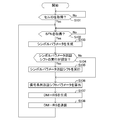
- the terminal device 20 when acquiring the SFN, the terminal device 20 makes a "Yes" determination, based on the acquired cell ID, and generates a symbol parameter n cell cs (n) for each of a plurality of symbol periods included in the radio frame (Step S103 in FIG. 10).
- the terminal device 20 determines whether or not the setting information represents performing symbol parameter cyclic shift (step S104 in FIG. 10).
- the setting information represents that symbol parameter cyclic shift is executed. Therefore, the terminal device 20 determines “Yes”, and executes a symbol parameter cyclic shift on the generated symbol parameter n cell cs (n) based on the acquired SFN (step S105 in FIG. 10).
- the terminal device 20 calculates the signal sequence cyclic shift parameter ⁇ (n) based on the symbol parameter n ′ cell cs (n) after execution of the symbol parameter cyclic shift (step S106 in FIG. 10).
- the terminal device 20 generates a DM-RS based on the calculated signal sequence cyclic shift parameter ⁇ (n) (step S107 in FIG. 10). Then, the terminal device 20 transmits the generated DM-RS in a radio frame having the acquired SFN (step S108 in FIG. 10). Thereafter, the terminal device 20 returns to step S102 in FIG. 10 and repeatedly executes the processing from step S102 to step S108. Note that the process of step S103 may be executed before the process of step S102. In addition, when the process of step S103 is repeatedly executed and the generated symbol parameter n cell cs (n) does not change, the process of step S103 may not be executed.
- the terminal apparatus 20 determines “No” in step S104, and does not execute the symbol parameter cyclic shift, and proceeds to step S106 in FIG. move on. In this case, the terminal device 20 calculates the signal sequence cyclic shift parameter ⁇ (n) based on the symbol parameter n cell cs (n) generated in step S103 (step S106 in FIG. 10).
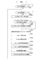
- the base station apparatus 10 executes the processing from step S201 to step S207 similar to the processing from step S101 to step S107 in FIG. 10.
- the base station apparatus 10 performs channel estimation based on the generated DM-RS (step S208 in FIG. 11).
- the base station apparatus 10 executes a correlation calculation process based on the channel estimation value, and executes an intra-frame averaging process for the result of the correlation calculation process (step S209 in FIG. 11).
- the base station apparatus 10 performs the inter-frame average process with respect to the result of the intra-frame average process (step S210 of FIG. 11).
- the base station apparatus 10 estimates the frequency deviation based on the result of the interframe averaging process (step S211 in FIG. 11). Then, the base station apparatus 10 performs demodulation with respect to the signal transmitted via PUCCH and PUSCH based on the frequency deviation estimated value (step S212 in FIG. 11). Thereafter, the base station apparatus 10 returns to step S202 in FIG. 11 and repeatedly executes the processing from step S202 to step S212.
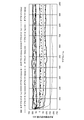
- FIG. 12 shows the change of the frequency deviation estimation value with respect to the subframe when the symbol parameter cyclic shift is not executed.
- the forgetting factor ⁇ is 0.9.
- the DM-RS and PUCCH used for PUCCH demodulation are allocated to radio resources at a period of 10 subframes. In other words, DM-RS and PUCCH used for demodulation of PUCCH are allocated to one subframe in one radio frame (having a time length of 10 ms in this example).
- the offset is the time difference between the head subframe in one radio frame and the subframe to which DM-RS is assigned in cell # 0 or cell # 1.
- the error of the frequency deviation estimated value tends to increase with respect to a specific offset.
- FIG. 13 shows a change C20 with respect to the subframe of the frequency deviation estimated value when the symbol parameter cyclic shift is executed.
- the first comparative example represents a change C21 with respect to the subframe of the frequency deviation estimated value when no interference wave exists.
- the second comparative example represents a change C22 with respect to the subframe of the frequency deviation estimated value when the symbol parameter cyclic shift is not performed. As shown in FIG. 13, the symbol parameter cyclic shift is executed, whereby the error of the frequency deviation estimated value can be suppressed.
- the terminal device 20 acquires the frame number of the radio frame. Furthermore, the terminal device 20 transmits a second signal sequence obtained by cyclically shifting the first signal sequence by the first shift amount based on the acquired frame number in a radio frame having the acquired frame number.
- the first shift amount can be changed based on the frame number. Therefore, the second signal sequence to be transmitted can be changed for each radio frame. As a result, it is possible to suppress the state in which the reception quality of the second signal sequence is excessively low from continuing. Therefore, the reception quality of the second signal sequence can be improved.
- the first shift amount is determined based on the second relationship and the identification information that identifies the period in which the second signal sequence is transmitted in the radio frame.
- the second relationship is a relationship in which the first relationship between the identification information for identifying each of the plurality of periods included in the radio frame and the shift amount is cyclically shifted by the second shift amount based on the frame number. is there.
- the first shift amount can be appropriately changed based on the frame number by appropriately changing the second shift amount based on the frame number.
- the first relationship includes a third relationship between the identification information and the parameter and a fourth relationship between the parameter and the shift amount. Further, the second shift amount is determined based on the frame number and the third relationship.
- the terminal device determines the second shift amount using a relationship different from the third relationship
- the terminal device must hold the relationship.
- the terminal device 20 does not have to hold a relationship different from the third relationship in order to determine the second shift amount. Therefore, the storage area used by the terminal device 20 can be reduced.
- the first relationship is determined based on an identifier that identifies a wireless area in which the second signal sequence is transmitted.
- the second signal sequences transmitted in parallel in the plurality of radio areas interfere with each other.
- the degree can be different for each radio frame. As a result, it is possible to suppress the state in which the reception quality of the second signal sequence is excessively low from continuing. Therefore, the reception quality of the second signal sequence can be improved.
- the base station apparatus 10 acquires the frame number of the radio frame. Furthermore, the base station apparatus 10 has received the second signal sequence obtained by cyclically shifting the first signal sequence by the first shift amount based on the acquired frame number and the radio frame having the acquired frame number. And channel estimation for a radio frame based on the signal.
- the first shift amount can be changed based on the frame number. Therefore, even if the cycle in which the second signal sequence is transmitted is a cycle obtained by multiplying the time length of the radio frame by a natural number, the second signal sequence to be transmitted can be changed for each radio frame. it can. As a result, it is possible to suppress the state in which the reception quality of the second signal sequence is excessively low from continuing. Therefore, the reception quality of the second signal sequence can be improved. As a result, the accuracy of channel estimation can be improved.
- the base station apparatus 10 uses different radio resources for transmission of signal sequences by the terminal apparatus 20 that performs symbol parameter cyclic shift and the terminal apparatus 20 or 30 that does not perform symbol parameter cyclic shift. Assigned to each.
- the signal sequence cyclic shift parameter ⁇ used to generate the signal sequence that is cyclically shifted based on the frame number and the signal sequence that is cyclically shifted not based on the frame number may be different from each other, It may be the same. Therefore, the signal sequence that is cyclically shifted based on the frame number and the signal sequence that is cyclically shifted not based on the frame number may not be orthogonal to each other.
- the two signal sequences when the two signal sequences are transmitted using the same radio resource, the two signal sequences may interfere with each other.
- the signal sequence that is cyclically shifted based on the frame number and the signal sequence that is cyclically shifted not based on the frame number are transmitted using different radio resources. The Therefore, the two signal sequences can be prevented from interfering with each other.
- the base station apparatus 10 includes a terminal apparatus 20 and a base station apparatus 10 that transmit a second signal sequence based on the result of channel estimation performed on each of a plurality of radio frames. Estimate the frequency difference between.
- Each of base station apparatus 10 and terminal apparatus 20 may cyclically shift symbol parameter series n cell cs based on Expression 17 instead of Expression 11.
- ⁇ represents an integer other than 0.
- each of the base station device 10 and the terminal device 20 may use the shift amount ⁇ SFN (i) instead of the shift amount ⁇ SFN (i) as the second shift amount.
- each of the base station apparatus 10 and the terminal apparatus 20 is configured to switch between a state in which symbol parameter cyclic shift is performed and a state in which symbol parameter cyclic shift is not performed.
- the terminal device 20 may be configured to have only a state in which symbol parameter cyclic shift is executed.
- the symbol parameter cyclic shift is performed on a signal transmitted from the terminal device 20 to the base station device 10 (in other words, an uplink signal).
- the object on which the symbol parameter cyclic shift is performed may be a signal (in other words, a downlink signal) transmitted from the base station apparatus 10 to the terminal apparatus 20.
- the object on which the symbol parameter cyclic shift is executed is DM-RS.
- the target on which the symbol parameter cyclic shift is executed may be a reference signal different from that of the DM-RS.
- the target on which the symbol parameter cyclic shift is executed may be a reference signal used for demodulation of a data signal, or may be a reference signal used for demodulation of both a data signal and a control signal.
- the object on which the symbol parameter cyclic shift is performed may be a signal different from the reference signal.
- radio communication system 10 base station apparatus 101 PUCCH resource allocation unit 102 PDSCH generation unit 103 CSI-RS generation unit 104 channel multiplexing unit 105 transmission RF unit 106 transmission antenna 107 symbol parameter generation unit 108 switching unit 109 symbol parameter cyclic shift unit 110 signal Sequence cyclic shift parameter calculation unit 111 Reception antenna 112 Reception RF unit 114 Channel estimation unit 115 Frequency deviation estimation unit 116 PUCCH demodulation unit 117 PUSCH demodulation unit 20 Terminal device 201 Reception antenna 202 Reception RF unit 203 PDSCH demodulation unit 204 CQI calculation unit 205 Symbol Parameter generation unit 206 Switching unit 207 Symbol parameter cyclic shift unit 208 Signal sequence cyclic shift parameter calculation unit 209 DM-RS generation unit 210 PUCCH raw Part 211 PUSCH generation unit 212 channel multiplexing unit 213 transmission RF unit 214 transmitting antenna 30 terminal NW network
Abstract
送信装置(20)は、無線により信号を送信する。送信装置(20)は、取得部(207)と送信部(207,208,209,212,213,214)とを備える。取得部(207)は、無線フレームのフレーム番号を取得する。送信部(207,208,209,212,213,214)は、上記取得されたフレーム番号に基づく第1のシフト量だけ第1の信号系列を巡回シフトさせた第2の信号系列を、上記取得されたフレーム番号を有する上記無線フレームにて送信する。
Description
本発明は、送信装置、受信装置、無線通信システム、及び、処理方法に関する。
無線により通信を行なう、送信装置及び受信装置を備える無線通信システムが知られている(例えば、非特許文献1を参照)。送信装置は、所定の方式に従って生成した信号系列を送信する。受信装置は、上記方式に従って生成した信号系列と、受信した信号と、に基づいてチャネル推定を行なう。上記方式においては、無線フレームに含まれる複数の期間の中から、第2の信号系列が送信される期間を識別する識別情報に基づいてシフト量が決定され、決定されたシフト量だけ第1の信号系列が巡回シフトさせられることにより第2の信号系列が生成される。
3GPP TS 36.211 V12.5.0、"Technical Specification Group Radio Access Network; Evolved Universal Terrestrial Radio Access (E-UTRA); Physical channels and modulation (Release 12)"、[online]、2015年3月、[平成27年6月15日検索]、インターネット〈URL:http://www.3gpp.org/ftp/Specs/archive/36_series/36.211/36211-c50.zip〉
ところで、第2の信号系列が送信される周期が、無線フレームの時間長を自然数倍した周期であることがある。この場合、第2の信号系列が送信される複数の無線フレームのそれぞれにて、第2の信号系列が送信される期間を識別する識別情報は、同一の情報である。従って、この場合、第2の信号系列が送信される複数の無線フレームのそれぞれにて、同一の信号系列が第2の信号系列として送信される。その結果、例えば、干渉波の存在によって第2の信号系列の受信品質が過度に低い状態が継続することがある。
一つの側面として、本発明の目的の一つは、信号系列の受信品質を高めることにある。
一つの側面では、送信装置は、無線により信号を送信する。
更に、この送信装置は、取得部と送信部とを備える。
上記取得部は、無線フレームのフレーム番号を取得する。
上記送信部は、上記取得されたフレーム番号に基づく第1のシフト量だけ第1の信号系列を巡回シフトさせた第2の信号系列を、上記取得されたフレーム番号を有する上記無線フレームにて送信する。
更に、この送信装置は、取得部と送信部とを備える。
上記取得部は、無線フレームのフレーム番号を取得する。
上記送信部は、上記取得されたフレーム番号に基づく第1のシフト量だけ第1の信号系列を巡回シフトさせた第2の信号系列を、上記取得されたフレーム番号を有する上記無線フレームにて送信する。
また、受信装置は、無線により信号を受信する。
更に、この受信装置は、取得部と推定部とを備える。
上記取得部は、無線フレームのフレーム番号を取得する。
上記推定部は、第2の信号系列と、上記取得されたフレーム番号を有する上記無線フレームにて受信された信号と、に基づいて、上記無線フレームに対するチャネル推定を行なう。上記第2の信号系列は、上記取得されたフレーム番号に基づく第1のシフト量だけ第1の信号系列を巡回シフトさせた信号系列である。
更に、この受信装置は、取得部と推定部とを備える。
上記取得部は、無線フレームのフレーム番号を取得する。
上記推定部は、第2の信号系列と、上記取得されたフレーム番号を有する上記無線フレームにて受信された信号と、に基づいて、上記無線フレームに対するチャネル推定を行なう。上記第2の信号系列は、上記取得されたフレーム番号に基づく第1のシフト量だけ第1の信号系列を巡回シフトさせた信号系列である。
信号系列の受信品質を高める。
以下、図面を参照して実施形態を説明する。ただし、以下に説明される実施形態は例示である。従って、以下に明示しない種々の変形や技術が実施形態に適用されることは排除されない。なお、以下の実施形態で用いる図面において、同一の符号を付した部分は、変更又は変形が明示されない限り、同一若しくは同様の部分を表す。
<第1実施形態>
(構成)
例えば、図1に表されるように、第1実施形態の無線通信システム1は、複数の基地局装置10と、複数の端末装置20と、複数の端末装置30と、を備える。無線通信システム1が備える基地局装置10の数は、1であってもよい。無線通信システム1が備える端末装置20の数は、1であってもよい。無線通信システム1が備える端末装置30の数は、1であってもよい。また、無線通信システム1は、端末装置30を備えなくてもよい。
(構成)
例えば、図1に表されるように、第1実施形態の無線通信システム1は、複数の基地局装置10と、複数の端末装置20と、複数の端末装置30と、を備える。無線通信システム1が備える基地局装置10の数は、1であってもよい。無線通信システム1が備える端末装置20の数は、1であってもよい。無線通信システム1が備える端末装置30の数は、1であってもよい。また、無線通信システム1は、端末装置30を備えなくてもよい。
無線通信システム1は、所定の通信方式に従って通信を行なう。本例では、通信方式は、LTE方式である。LTEは、Long Term Evolutionの略記である。なお、通信方式は、LTE方式と異なる方式(例えば、LTE-Advanced等の方式)であってもよい。
基地局装置10は、セルを形成する。なお、基地局装置10は、複数のセルを形成してもよい。セルは、無線エリアの一例である。無線エリアは、カバレッジ・エリア、又は、通信エリアと表されてもよい。例えば、セルは、マクロセル、マイクロセル、ナノセル、ピコセル、フェムトセル、ホームセル、スモールセル、又は、セクタセル等である。
基地局装置10は、当該基地局装置10が形成するセル内に位置する端末装置20及び30と無線により通信する。
本例では、基地局装置10は、当該基地局装置10が形成するセルにおいて無線リソースを提供する。本例では、無線リソースは、時間及び周波数により識別される。
本例では、基地局装置10は、当該基地局装置10が形成するセルにおいて無線リソースを提供する。本例では、無線リソースは、時間及び周波数により識別される。
OFDMにおける1つのサブキャリアの、1つのOFDMシンボルの時間に対応する無線リソースは、リソースエレメント(RE;Resource Element)と表されてよい。OFDMは、Orthogonal Frequency-Division Multiplexingの略記である。
換言すると、無線リソースは、時間及び周波数の組み合わせが互いに異なる複数のREを含む。本例では、時間軸に沿って連続する7個のREに対応する期間は、スロットと呼ばれる。また、時間軸に沿って連続する2つのスロットは、1つのサブフレームを形成する。更に、時間軸に沿って連続する10個のサブフレームは、1つの無線フレームを形成する。
本例では、時間軸において1つのスロットに含まれるREのうちの、周波数軸に沿って連続する12個のサブキャリアに対応するREは、リソースブロック(RB;Resource Block)と呼ばれる。従って、本例では、1つのRBは、84(=12×7)個のREからなる。
基地局装置10は、当該基地局装置10が形成するセル内に位置する端末装置20及び30と、当該セルにおいて提供している無線リソースを用いることにより通信を行なう。
基地局装置10は、基地局、eNB(Evolved Node B)、無線装置、又は、無線通信装置と表されてもよい。基地局装置10は、受信装置の一例である。
基地局装置10は、基地局、eNB(Evolved Node B)、無線装置、又は、無線通信装置と表されてもよい。基地局装置10は、受信装置の一例である。
本例では、基地局装置10は、通信可能に通信網(例えば、コアネットワーク)NWに接続されている。基地局装置10と通信網NWとの間のインタフェースは、S1インタフェースと表されてもよい。また、基地局装置10間のインタフェースは、X2インタフェースと表されてもよい。
無線通信システム1のうちの基地局装置10よりも通信網NW(即ち、上位)側の部分は、EPCと表されてよい。EPCは、Evolved Packet Coreの略記である。無線通信システム1のうちの基地局装置10により形成される部分は、E-UTRANと表されてよい。E-UTRANは、Evolved Universal Terrestrial Radio Access Networkの略記である。
端末装置20又は30は、当該端末装置20又は30が位置するセルにおいて提供されている無線リソースを用いて、当該セルを形成する基地局装置10と無線により通信する。なお、端末装置20又は30は、無線端末、無線機器、又は、ユーザ端末(UE;User Equipment)と表されてよい。端末装置20又は30は、送信装置の一例である。
(構成;端末装置)
次に、端末装置20の構成について説明する。
例えば、図2に表されるように、端末装置20は、受信アンテナ201と、受信RF部202と、PDSCH復調部203と、CQI算出部204と、を備える。RFは、Radio Frequencyの略記である。PDSCHは、Physical Downlink Shared Channelの略記である。CQIは、Channel Quality Indicatorの略記である。
次に、端末装置20の構成について説明する。
例えば、図2に表されるように、端末装置20は、受信アンテナ201と、受信RF部202と、PDSCH復調部203と、CQI算出部204と、を備える。RFは、Radio Frequencyの略記である。PDSCHは、Physical Downlink Shared Channelの略記である。CQIは、Channel Quality Indicatorの略記である。
更に、例えば、端末装置20は、シンボルパラメータ生成部205と、切替部206と、シンボルパラメータ巡回シフト部207と、信号系列巡回シフトパラメータ算出部208と、を備える。
加えて、例えば、端末装置20は、DM-RS生成部209と、PUCCH生成部210と、PUSCH生成部211と、チャネル多重部212と、送信RF部213と、送信アンテナ214と、を備える。DM-RSは、Demodulation Reference Signalの略記である。PUCCHは、Physical Uplink Control Channelの略記である。PUSCHは、Physical Uplink Shared Channelの略記である。
PDSCH及びPUSCHのそれぞれは、データ信号の送信に用いられる通信チャネルの一例である。PUCCHは、制御信号の送信に用いられる通信チャネルの一例である。
受信RF部202は、受信アンテナ201を介して受信した無線信号をベースバンド信号(換言すると、BB信号)に変換する受信RF処理を実行する。例えば、受信RF処理は、無線周波数から基底周波数への変換(換言すると、ダウンコンバージョン)と、アナログ信号からデジタル信号への変換と、を含む。受信RF部202は、BB信号をPDSCH復調部203及びCQI算出部204のそれぞれへ出力する。
PDSCH復調部203は、受信RF部202から入力されたBB信号のうちの、PDSCHに割り当てられた無線リソースを用いて送信された信号に対する復調を実行する。PDSCH復調部203は、復調によって得られた情報を、切替部206、信号系列巡回シフトパラメータ算出部208、DM-RS生成部209、及び、PUCCH生成部210のそれぞれへ出力する。
本例では、復調によって得られた情報は、PUCCHリソース情報と、後述する設定情報と、を含む。本例では、PUCCHリソース情報は、基地局装置10と端末装置20との間の通信においてPUCCHに割り当てられる無線リソースと関連付けられた情報である。PUCCHリソース情報は、PUCCHリソースインデックスと表されてもよい。
CQI算出部204は、受信RF部202から入力されたBB信号に基づいてCQIを算出する。例えば、CQIは、CSI-RSに基づいて算出される。CSI-RSは、Channel State Information Reference Signalの略記である。CQIは、通信チャネルの受信品質を表す情報の一例である。CQI算出部204は、算出したCQIをPUCCH生成部210へ出力する。
シンボルパラメータ生成部205、切替部206、シンボルパラメータ巡回シフト部207、及び、信号系列巡回シフトパラメータ算出部208については後述する。なお、後述するように、信号系列巡回シフトパラメータ算出部208は、信号系列巡回シフトパラメータαを算出し、算出した信号系列巡回シフトパラメータαをDM-RS生成部209及びPUCCH生成部210のそれぞれへ出力する。
DM-RS生成部209は、信号系列巡回シフトパラメータ算出部208から入力された信号系列巡回シフトパラメータαに基づいてDM-RSを生成する。DM-RSは、後述するように、PUCCHを介して送信される制御信号の復調に用いられる参照信号である。DM-RS生成部209は、生成したDM-RSをチャネル多重部212へ出力する。
本例では、DM-RS生成部209は、数式1に基づいて、DM-RSとして送信される信号系列r(α)
u,ν(q)を生成する。qは、0以上であり、且つ、MRS
scよりも小さい各整数を表す。MRS
scは、DM-RSに含まれる信号の数を表す。DM-RSに含まれるMRS
sc個の信号は、MRS
sc個のREを用いてそれぞれ送信される。本例では、MRS
scは、1つのRBに含まれるサブキャリアの数に等しい。jは、虚数単位を表す。

本例では、rbase
u,ν(q)は、ベース系列と表される。DM-RS生成部209は、数式2に基づいて、ベース系列rbase
u,ν(q)を生成する。

φ(q)は、例えば、図3に表されるように、パラメータuと関連付けて予め定められている。DM-RS生成部209は、パラメータuを、数式3乃至数式5に基づいて算出する。


本例では、DM-RS生成部209は、パラメータnRS
IDとして、セルを識別する識別子(換言すると、セル識別子)を用いる。セル識別子は、セルIDと表されてよい。DM-RS生成部209は、端末装置20が位置するセルを識別するセル識別子を取得する。例えば、セル識別子は、基地局装置10から端末装置20へ送信される。また、セル識別子は、基地局装置10から端末装置20へ送信された情報に基づいて端末装置20により取得されてもよい。また、DM-RS生成部209は、パラメータnRS
IDとして、無線通信システム1によって設定された値を用いてもよい。
nsは、スロット番号を表す。スロット番号は、各無線フレームにおいて、スロットを識別するための情報である。本例では、スロット番号は、0から開始し、且つ、無線フレームにおいて時間軸に沿って時間が進む方向にてスロット毎に1ずつ増加する。
cは、0及び1の2つの値から選択された値の疑似ランダム系列を表す。本例では、疑似ランダム系列は、Gold系列である。なお、疑似ランダム系列は、Gold系列と異なる系列であってよい。本例では、DM-RS生成部209は、疑似ランダム系列c(x)を、数式6により表される初期化パラメータcinitを用いて初期化する。初期化パラメータcinitは、シードと表されてもよい。従って、本例では、疑似ランダム系列c(x)は、パラメータnRS
ID(本例では、セル識別子)に基づいて決定される。

換言すると、本例では、数式1に表されるように、DM-RS生成部209は、ベース系列rbase
u,ν(q)を、周波数領域において信号系列巡回シフトパラメータαだけ位相回転させる。本例では、周波数領域における位相回転は、時間領域における巡回シフトに対応する。従って、信号系列巡回シフトパラメータαは、時間領域における巡回シフトのシフト量に対応する。ベース系列rbase
u,ν(q)は、第1の信号系列の一例である。信号系列r(α)
u,ν(q)は、第2の信号系列の一例である。信号系列巡回シフトパラメータαは、第1のシフト量の一例である。なお、巡回シフトは、循環シフトと表されてもよい。
PUCCH生成部210は、CQI算出部204から入力されたCQIと、信号系列巡回シフトパラメータ算出部208から入力された信号系列巡回シフトパラメータαと、に基づいて、PUCCHを介して送信される制御信号を生成する。PUCCHを介して送信される制御信号は、PUCCH信号と表されてよい。
本例では、PUCCH生成部210は、信号系列巡回シフトパラメータαに基づいて、CQIを表す信号を周波数領域において位相回転させることにより、PUCCH信号を生成する。なお、通信チャネルを介した送信は、通信チャネルに割り当てられた無線リソースを用いた送信と表されてもよい。PUCCH生成部210は、生成した制御信号をチャネル多重部212へ出力する。
PUSCH生成部211は、ユーザデータに基づいて、PUSCHを介して送信されるデータ信号を生成し、生成したデータ信号をチャネル多重部212へ出力する。例えば、ユーザデータは、端末装置20のユーザによって入力された情報である。
チャネル多重部212は、DM-RS生成部209、PUCCH生成部210、及び、PUSCH生成部211から入力された信号を多重し、多重された信号を送信RF部213へ出力する。本例では、信号の多重は、PUCCH信号及びDM-RSの生成に用いられたフレーム番号を有する無線フレームにて、当該PUCCH信号及び当該DM-RSが送信されるように行なわれる。
本例では、PUCCH信号及びDM-RSの送信に対する無線リソースの割り当ては、所定のフォーマットに従って行なわれる。フォーマットは、PUCCH format 2と表されてよい。
例えば、PUCCH信号及びDM-RSの送信は、所定の送信周期(本例では、無線フレームの時間長を自然数倍した周期)毎に、1つのサブフレームに割り当てられる。更に、例えば、図4に表されるように、PUCCH信号及びDM-RSの送信は、システム帯域幅に含まれる複数のRBのうちの、周波数軸に沿った方向における両端部のRB901~908に割り当てられる。
更に、例えば、図4に表されるように、1つのRBにおいて、2つのシンボル期間(本例では、ST#1及びST#5)のそれぞれにDM-RSが割り当てられる。シンボル期間は、1つのREに対応する期間である。更に、例えば、図4に表されるように、1つのRBにおいて、残余の5つのシンボル期間(本例では、ST#0、ST#2~ST#4、及び、ST#6)のそれぞれにPUCCH信号が割り当てられる。
本例では、後述するように、信号系列巡回シフトパラメータαは、端末装置20毎に決定されるパラメータに基づいて算出される。また、異なる複数の信号系列巡回シフトパラメータαに基づいてそれぞれ位相回転させられた複数の信号は、互いに直交する。
従って、本例では、PUCCH信号及びDM-RSは、複数の端末装置20のそれぞれから送信されることにより、符号多重された信号として基地局装置10により受信される。例えば、図4に表されるように、第1乃至第3の端末装置20からそれぞれ送信された信号S-UE#0乃至#2は、符号多重された信号として基地局装置10により受信される。
更に、例えば、PUCCH信号及びDM-RSの送信は、PUCCHリソース情報n(2,p)
PUCCHに関連付けられたRBに割り当てられる。本例では、図4に表されるように、PUCCH信号及びDM-RSの送信に割り当てられるRBは、パラメータmと関連付けて予め定められる。本例では、連続する2つのスロットにおいて、同一のパラメータmと関連付けられるRBは、異なる周波数を有する。換言すると、PUCCH信号及びDM-RSの送信に割り当てられる無線リソースには、周波数ホッピングが適用される。
本例では、パラメータmは、数式7により表される。NRB
scは、1つのRBに含まれるサブキャリアの数を表す。

送信RF部213は、チャネル多重部212から入力されたBB信号を無線信号に変換する送信RF処理を実行する。例えば、送信RF処理は、デジタル信号からアナログ信号への変換と、基底周波数から無線周波数への変換(換言すると、アップコンバージョン)と、を含む。送信RF部213は、無線信号を送信アンテナ214を介して送信する。
ここで、シンボルパラメータ生成部205、切替部206、シンボルパラメータ巡回シフト部207、及び、信号系列巡回シフトパラメータ算出部208について説明を加える。
シンボルパラメータ生成部205は、端末装置20が位置するセルを識別するセル識別子を取得する。例えば、セル識別子は、基地局装置10から端末装置20へ送信される。また、セル識別子は、基地局装置10から端末装置20へ送信された情報に基づいて端末装置20により取得されてもよい。
シンボルパラメータ生成部205は、数式8に基づいて、無線フレームに含まれる複数のシンボル期間のそれぞれに対するシンボルパラメータncell cs(n)を生成する。

シンボルパラメータ生成部205は、数式8に基づいて、無線フレームに含まれる複数のシンボル期間のそれぞれに対するシンボルパラメータncell cs(n)を生成する。
nは、シンボル期間番号を表す。シンボル期間番号nは、各無線フレームにおいて、シンボル期間を識別するための情報である。本例では、シンボル期間番号は、0から開始し、且つ、無線フレームにおいて時間軸に沿って時間が進む方向にてシンボル期間毎に1ずつ増加する。シンボル期間番号nは、無線フレームに含まれる複数の期間のそれぞれを識別する識別情報の一例である。数式8により表される、シンボル期間番号nと、シンボルパラメータncell
cs(n)と、の関係は、第3の関係の一例である。
従って、シンボル期間番号nは、0以上であり、且つ、Nsymbよりも小さい各整数を表す。Nsymbは、1つの無線フレームに含まれるシンボル期間の数(換言すると、シンボル期間数)を表す。シンボル期間数Nsymbは、数式9により表される。NUL
symbは、1つのスロットに含まれるシンボル期間の数を表す。Nframe
slotは、1つの無線フレームに含まれるスロットの数を表す。本例では、シンボル期間数Nsymbは、140である。

無線フレームに含まれる複数のシンボル期間のそれぞれに対して生成されたシンボルパラメータncell
cs(0),…,ncell
cs(Nsymb-1)は、シンボルパラメータ系列ncell
csと表されてよい。
本例では、シンボルパラメータ生成部205は、DM-RS生成部209と同様に、取得したセル識別子と数式6とに基づいて、疑似ランダム系列c(x)を初期化する。従って、本例では、シンボルパラメータncell cs(n)は、端末装置20が位置するセルを識別するセル識別子に基づいて決定される。なお、シンボルパラメータ生成部205は、疑似ランダム系列c(x)をDM-RS生成部209と共用してもよい。
本例では、シンボルパラメータ生成部205は、DM-RS生成部209と同様に、取得したセル識別子と数式6とに基づいて、疑似ランダム系列c(x)を初期化する。従って、本例では、シンボルパラメータncell cs(n)は、端末装置20が位置するセルを識別するセル識別子に基づいて決定される。なお、シンボルパラメータ生成部205は、疑似ランダム系列c(x)をDM-RS生成部209と共用してもよい。
なお、シンボル期間番号nは、数式10により表されてもよい。lは、シンボル番号を表す。シンボル番号は、各スロットにおいて、シンボル期間を識別するための情報である。本例では、シンボル番号は、0から開始し、且つ、スロットにおいて時間軸に沿って時間が進む方向にてシンボル期間毎に1ずつ増加する。

シンボルパラメータ生成部205は、生成したシンボルパラメータ系列ncell
csを切替部206へ出力する。
切替部206は、入力された設定情報に基づいて、シンボルパラメータ巡回シフト部207及び信号系列巡回シフトパラメータ算出部208のうちの一方へ、シンボルパラメータ生成部205から入力されたシンボルパラメータ系列ncell csを出力する。本例では、設定情報は、後述するシンボルパラメータ巡回シフトを実行するか否かを表す。例えば、設定情報は、基地局装置10から端末装置20へ送信されてよい。
切替部206は、入力された設定情報に基づいて、シンボルパラメータ巡回シフト部207及び信号系列巡回シフトパラメータ算出部208のうちの一方へ、シンボルパラメータ生成部205から入力されたシンボルパラメータ系列ncell csを出力する。本例では、設定情報は、後述するシンボルパラメータ巡回シフトを実行するか否かを表す。例えば、設定情報は、基地局装置10から端末装置20へ送信されてよい。
切替部206は、設定情報が、シンボルパラメータ巡回シフトを実行することを表す場合、シンボルパラメータ巡回シフト部207へ、シンボルパラメータ系列ncell
csを出力する。切替部206は、設定情報が、シンボルパラメータ巡回シフトを実行しないことを表す場合、信号系列巡回シフトパラメータ算出部208へ、シンボルパラメータ系列ncell
csを出力する。
シンボルパラメータ巡回シフト部207は、無線フレームのフレーム番号を取得する。フレーム番号は、SFN(System Frame Number)と表されてもよい。例えば、フレーム番号は、基地局装置10から端末装置20へ送信される。また、フレーム番号は、基地局装置10から端末装置20へ送信された情報に基づいて端末装置20により取得されてもよい。シンボルパラメータ巡回シフト部207は、取得部の一例である。
シンボルパラメータ巡回シフト部207は、取得したフレーム番号iに基づいて、切替部206から入力されたシンボルパラメータ系列ncell
csをシフト量ΔSFN(i)だけ巡回シフトさせる。本例では、iは、0から所定の最大番号までの各整数を表す。最大番号は、例えば、1023である。なお、シフト量は、ΔSFN(i) mod Nsymbであると捉えられてもよい。また、本例では、演算子modにより算出される剰余は、正の数である。なお、シンボルパラメータ系列ncell
csの巡回シフトは、シンボルパラメータ巡回シフトと表されてよい。

本例では、シフト量ΔSFN(i)と、巡回シフトさせられたシンボルパラメータ系列n’cell
csと、の関係は、図5のように表される。
本例では、シンボルパラメータ巡回シフト部207は、数式12に基づいてシフト量ΔSFN(i)を算出する。換言すると、シフト量ΔSFN(i)は、数式8により表される、シンボル期間番号nと、シンボルパラメータncell cs(n)と、の関係と、取得したフレーム番号iと、に基づいて決定される。シフト量ΔSFN(i)は、第2のシフト量の一例である。

本例では、シンボルパラメータ巡回シフト部207は、数式12に基づいてシフト量ΔSFN(i)を算出する。換言すると、シフト量ΔSFN(i)は、数式8により表される、シンボル期間番号nと、シンボルパラメータncell cs(n)と、の関係と、取得したフレーム番号iと、に基づいて決定される。シフト量ΔSFN(i)は、第2のシフト量の一例である。
シンボルパラメータ巡回シフト部207は、巡回シフトさせられたシンボルパラメータ系列n’cell
csを信号系列巡回シフトパラメータ算出部208へ出力する。
信号系列巡回シフトパラメータ算出部208は、信号系列巡回シフトパラメータα(n)を算出する。信号系列巡回シフトパラメータα(n)の算出は、切替部206から入力されたシンボルパラメータ系列ncell
cs、又は、シンボルパラメータ巡回シフト部207から入力されたシンボルパラメータ系列n’cell
csに基づいて行なわれる。本例では、信号系列巡回シフトパラメータ算出部208は、数式13に基づいて信号系列巡回シフトパラメータα(n)を算出する。

信号系列巡回シフトパラメータ算出部208は、切替部206からシンボルパラメータ系列ncell
csが入力された場合、数式14に基づいて、パラメータn(p)
cs(n)を算出する。n’p(ns)は、PUCCHリソース情報に基づいて決定されるパラメータである。従って、パラメータn’p(ns)は、端末装置20毎に決定される。数式13及び数式14により表される、シンボルパラメータncell
cs(n)と、信号系列巡回シフトパラメータα(n)と、の関係は、第4の関係の一例である。また、数式8、数式13、及び、数式14により表される、シンボル期間番号nと、信号系列巡回シフトパラメータα(n)と、の関係は、第1の関係の一例である。

信号系列巡回シフトパラメータ算出部208は、シンボルパラメータ巡回シフト部207からシンボルパラメータ系列n’cell
csが入力された場合、数式15に基づいて、パラメータn(p)
cs(n)を算出する。数式8、数式11乃至数式13、及び、数式15により表される、シンボル期間番号nと、信号系列巡回シフトパラメータα(n)と、の関係は、第2の関係の一例である。

信号系列巡回シフトパラメータ算出部208は、算出した信号系列巡回シフトパラメータα(n)をDM-RS生成部209及びPUCCH生成部210のそれぞれへ出力する。
DM-RS生成部209は、入力された信号系列巡回シフトパラメータα(n)のうちの、生成する予定のDM-RSの送信に割り当てられるシンボル期間に関連付けられた信号系列巡回シフトパラメータα(n)に基づいて当該DM-RSを生成する。PUCCH生成部210は、入力された信号系列巡回シフトパラメータα(n)のうちの、生成する予定のPUCCH信号の送信に割り当てられるシンボル期間に関連付けられた信号系列巡回シフトパラメータα(n)に基づいて当該PUCCH信号を生成する。
なお、数式14に基づいて算出された信号系列巡回シフトパラメータα(n)に基づいて生成されたDM-RSは、フレーム番号に基づかずに巡回シフトさせられた信号系列の一例である。また、数式15に基づいて算出された信号系列巡回シフトパラメータα(n)に基づいて生成されたDM-RSは、フレーム番号に基づいて巡回シフトさせられた信号系列の一例である。
ここで、信号系列巡回シフトパラメータ算出部208により出力される信号系列巡回シフトパラメータα(n)について説明を加える。
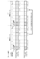
先ず、設定情報が、シンボルパラメータ巡回シフトを実行しないことを表す場合について説明する。この場合、図6に表されるように、シンボル期間番号nに対する信号系列巡回シフトパラメータα(n)の算出には、シンボルパラメータ生成部205により生成されたシンボルパラメータncell
cs(n)が用いられる。
シンボル期間番号nに対する信号系列巡回シフトパラメータα(n)の算出に用いられるシンボルパラメータncell
cs(n)は、フレーム番号iの無線フレームと、フレーム番号i+1の無線フレームと、の間で変化しない。換言すると、各端末装置20は、同一のシンボル期間番号nに対して、無線フレーム間で共通するシンボルパラメータncell
cs(n)を用いて、信号系列巡回シフトパラメータα(n)を算出する。
従って、セル#0及び#1にそれぞれ位置する第1及び第2の端末装置20が、同一のシンボル期間番号nに対する信号系列巡回シフトパラメータα(n)の算出に用いるシンボルパラメータncell
cs(n)の組み合わせは、無線フレーム間で変化しない。その結果、例えば、第1及び第2の端末装置20により送信されるDM-RSが互いに干渉する程度は、無線フレームが変化しても変化しにくい。
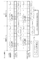
次に、設定情報が、シンボルパラメータ巡回シフトを実行することを表す場合について説明する。この場合、図7に表されるように、シンボル期間番号nに対する信号系列巡回シフトパラメータα(n)の算出には、信号系列巡回シフトパラメータ算出部208により巡回シフトさせられたシンボルパラメータn’cell
cs(n)が用いられる。
信号系列巡回シフトパラメータα(n)の算出に用いられるシンボルパラメータn’cell
cs(n)は、フレーム番号iの無線フレームにおいてシンボルパラメータncell
cs{(n-ΔSFN(i)) mod Nsymb}である。また、信号系列巡回シフトパラメータα(n)の算出に用いられるシンボルパラメータn’cell
cs(n)は、フレーム番号i+1の無線フレームにおいてシンボルパラメータncell
cs{(n-ΔSFN(i+1)) mod Nsymb}である。
このように、シンボル期間番号nに対する信号系列巡回シフトパラメータα(n)の算出に用いられるシンボルパラメータn’cell
cs(n)は、フレーム番号iの無線フレームと、フレーム番号i+1の無線フレームと、の間で変化する。換言すると、各端末装置20は、同一のシンボル期間番号nに対して、無線フレーム間で異なるシンボルパラメータn’cell
cs(n)を用いて、信号系列巡回シフトパラメータα(n)を算出する。
更に、本例では、シフト量ΔSFN(i)は、数式8及び数式12に表されるように、同一のフレーム番号iに対して、セル間で異なる値を有する。
従って、セル#0及び#1にそれぞれ位置する第1及び第2の端末装置20が、同一のシンボル期間番号nに対する信号系列巡回シフトパラメータα(n)の算出に用いるシンボルパラメータncell
cs(n)の組み合わせは、無線フレーム間で変化する。その結果、例えば、第1及び第2の端末装置20により送信されるDM-RSが互いに干渉する程度は、無線フレームの変化に伴って変化しやすい。
シンボルパラメータ巡回シフト部207、信号系列巡回シフトパラメータ算出部208、DM-RS生成部209、チャネル多重部212、送信RF部213、及び、送信アンテナ214は、送信部の一例である。
なお、端末装置20が備える受信アンテナ201の数は、2以上であってもよい。また、端末装置20が備える送信アンテナ214の数は、2以上であってもよい。また、端末装置20は、受信アンテナ201及び送信アンテナ214に代えて、受信アンテナ201及び送信アンテナ214のそれぞれとして機能する共用アンテナを備えてもよい。
受信RF部202及び送信RF部213は、LSI(Large Scale Integration)を用いて実現されてよい。LSIは、プログラム可能な論理回路装置(例えば、PLD、又は、FPGA)であってもよい。PLDは、Programmable Logic Deviceの略記である。FPGAは、Field-Programmable Gate Arrayの略記である。
端末装置20が備える各部203~212は、処理装置及び記憶装置を用いて実現されてよい。処理装置は、CPU(Central Processing Unit)、又は、DSP(Digital Signal Processor)であってよい。
なお、端末装置30は、シンボルパラメータ巡回シフトを実行する機能を有しない点を除いて、端末装置20と同様の構成を有する。
(構成;基地局装置)
次に、基地局装置10の構成について説明する。
例えば、図8に表されるように、基地局装置10は、PUCCHリソース割当部101と、PDSCH生成部102と、CSI-RS生成部103と、チャネル多重部104と、送信RF部105と、送信アンテナ106と、を備える。
次に、基地局装置10の構成について説明する。
例えば、図8に表されるように、基地局装置10は、PUCCHリソース割当部101と、PDSCH生成部102と、CSI-RS生成部103と、チャネル多重部104と、送信RF部105と、送信アンテナ106と、を備える。
更に、例えば、基地局装置10は、シンボルパラメータ生成部107と、切替部108と、シンボルパラメータ巡回シフト部109と、信号系列巡回シフトパラメータ算出部110と、を備える。
加えて、例えば、基地局装置10は、受信アンテナ111と、受信RF部112と、チャネル推定部114と、周波数偏差推定部115と、PUCCH復調部116と、PUSCH復調部117と、を備える。
PUCCHリソース割当部101は、端末情報を取得する。本例では、端末情報は、端末装置20又は30を識別する端末識別子と、端末装置20又は30がシンボルパラメータ巡回シフトを実行可能か否かを表す情報と、を含む。例えば、端末情報は、端末装置20又は30から基地局装置10へ送信される。また、基地局装置10は、無線通信システム1に含まれる端末装置20及び30と異なる装置から端末情報を受信してもよい。
PUCCHリソース割当部101は、取得した端末情報に基づいて、設定情報及びPUCCHリソース情報を決定する。シンボルパラメータ巡回シフトを実行可能である端末装置20に対して、シンボルパラメータ巡回シフトを実行することを表す設定情報が決定されてよい。シンボルパラメータ巡回シフトを実行不能である端末装置30に対して、シンボルパラメータ巡回シフトを実行しないことを表す設定情報が決定される。
シンボルパラメータ巡回シフトを実行することを表す設定情報が決定された端末装置20は、実行端末装置と表されてよい。シンボルパラメータ巡回シフトを実行しないことを表す設定情報が決定された端末装置20又は30は、不実行端末装置と表されてよい。
本例では、PUCCHリソース割当部101は、実行端末装置20及び不実行端末装置20又は30に対して、互いに異なるPUCCHリソース情報を決定する。これにより、PUCCHリソース割当部101は、実行端末装置20及び不実行端末装置20又は30による、DM-RS及びPUCCH信号の送信に、互いに異なる無線リソースをそれぞれ割り当てる。PUCCHリソース割当部101は、割当部の一例である。
PUCCHリソース割当部101は、決定したPUCCHリソース情報及び設定情報を、PDSCH生成部102、切替部108、信号系列巡回シフトパラメータ算出部110、チャネル推定部114、及び、PUCCH復調部116のそれぞれへ出力する。
PDSCH生成部102は、PUCCHリソース割当部101から入力されたPUCCHリソース情報及び設定情報と、ユーザデータと、に基づいて、PDSCHを介して送信されるデータ信号を生成し、生成したデータ信号をチャネル多重部104へ出力する。例えば、ユーザデータは、データ信号の送信先の端末装置20又は30と異なる端末装置20又は30から送信された情報、又は、無線通信システム1に含まれる端末装置20及び30と異なる装置から送信された情報である。
CSI-RS生成部103は、CSI-RSを生成し、生成したCSI-RSをチャネル多重部104へ出力する。
チャネル多重部104は、PDSCH生成部102、及び、CSI-RS生成部103から入力された信号を多重し、多重された信号を送信RF部105へ出力する。
送信RF部105は、チャネル多重部104から入力されたBB信号を無線信号に変換する送信RF処理を実行する。送信RF部105は、無線信号を送信アンテナ106を介して送信する。
チャネル多重部104は、PDSCH生成部102、及び、CSI-RS生成部103から入力された信号を多重し、多重された信号を送信RF部105へ出力する。
送信RF部105は、チャネル多重部104から入力されたBB信号を無線信号に変換する送信RF処理を実行する。送信RF部105は、無線信号を送信アンテナ106を介して送信する。
シンボルパラメータ生成部107は、基地局装置10が保持しているセル識別子を用いる点を除いて、シンボルパラメータ生成部205と同様に機能する。
切替部108は、PUCCHリソース割当部101から入力された設定情報を用いる点を除いて、切替部206と同様に機能する。
シンボルパラメータ巡回シフト部109は、基地局装置10が保持しているフレーム番号を用いる点を除いて、シンボルパラメータ巡回シフト部207と同様に機能する。シンボルパラメータ巡回シフト部109は、取得部の一例である。
切替部108は、PUCCHリソース割当部101から入力された設定情報を用いる点を除いて、切替部206と同様に機能する。
シンボルパラメータ巡回シフト部109は、基地局装置10が保持しているフレーム番号を用いる点を除いて、シンボルパラメータ巡回シフト部207と同様に機能する。シンボルパラメータ巡回シフト部109は、取得部の一例である。
信号系列巡回シフトパラメータ算出部110は、PUCCHリソース割当部101から入力されたPUCCHリソース情報を用いる点と、パラメータα(n)の出力先と、を除いて、信号系列巡回シフトパラメータ算出部208と同様に機能する。信号系列巡回シフトパラメータ算出部110は、信号系列巡回シフトパラメータα(n)を、チャネル推定部114及びPUCCH復調部116のそれぞれへ出力する。
受信RF部112は、受信アンテナ111を介して受信した無線信号をBB信号に変換する受信RF処理を実行する。受信RF部112は、BB信号を、チャネル推定部114、PUCCH復調部116、及び、PUSCH復調部117のそれぞれへ出力する。
PUCCH復調部116は、入力されたPUCCHリソース情報と、入力された信号系列巡回シフトパラメータα(n)と、後述する、チャネル推定値及び周波数偏差推定値と、に基づいて、PUCCHを介して送信された信号に対する復調を実行する。本例では、復調によって得られた情報は、CQIを含む。
PUSCH復調部117は、後述する周波数偏差推定値に基づいて、受信RF部112から入力されたBB信号のうちの、PUSCHを介して送信された信号に対する復調を実行する。本例では、復調によって得られた情報は、ユーザデータを含む。
チャネル推定部114は、信号系列巡回シフトパラメータ算出部110から入力された信号系列巡回シフトパラメータα(n)に基づいて、DM-RS生成部209と同様に、DM-RS(換言すると、レプリカ信号)を生成する。
更に、チャネル推定部114は、生成したレプリカ信号と、受信RF部112から入力されたBB信号のうちの、DM-RSの送信に割り当てられた無線リソースを用いて送信された信号と、に基づいてチャネル推定を行なう。本例では、チャネル推定に用いられる信号は、レプリカ信号の生成に用いられたフレーム番号を有する無線フレームにて受信された信号である。
例えば、チャネル推定は、通信チャネルの状態の推定である。チャネル推定の結果は、チャネル推定値と表されてよい。チャネル推定部114は、チャネル推定値を周波数偏差推定部115及びPUCCH復調部116のそれぞれへ出力する。
周波数偏差推定部115は、チャネル推定部114から入力されたチャネル推定値に基づいて、基地局装置10と端末装置20又は30との間の周波数の差(換言すると、周波数偏差)を推定する。周波数偏差は、周波数差と表されてもよい。周波数偏差の推定の結果は、周波数偏差推定値と表されてよい。周波数偏差推定部115は、周波数偏差推定値をPUCCH復調部116及びPUSCH復調部117のそれぞれへ出力する。
本例では、図9に表されるように、周波数偏差推定部115は、各スロットに対して、2つのシンボル期間のうちの一方におけるチャネル推定値に対する複素共役処理を行なう。本例では、ha,b(f)は、スロット番号aのスロットに含まれ、且つ、シンボル番号bのシンボル期間に含まれるREのうちのf番目のREに対するチャネル推定値を表す。本例では、fは、0以上であり、且つ、NRB
scよりも小さい各整数を表す。
本例では、スロット#0における2つのシンボル期間のうちの一方におけるチャネル推定値は、h0,1(0),…,h0,1(11)により表される。同様に、スロット#1における2つのシンボル期間のうちの一方におけるチャネル推定値は、h1,1(0),…,h1,1(11)により表される。
更に、周波数偏差推定部115は、各スロットに対して、2つのシンボル期間のうちの他方におけるチャネル推定値と、複素共役処理の実行後のチャネル推定値と、の間で、相関演算処理を行なう。
本例では、スロット#0における2つのシンボル期間のうちの他方におけるチャネル推定値は、h0,5(0),…,h0,5(11)により表される。同様に、スロット#1における2つのシンボル期間のうちの他方におけるチャネル推定値は、h1,5(0),…,h1,5(11)により表される。
加えて、周波数偏差推定部115は、各サブフレームに対して、連続する2つのスロットのそれぞれに対する相関演算処理の結果に対するフレーム内平均処理を行なう。例えば、フレーム内平均処理は、2つのスロットのそれぞれに対する相関演算処理の結果を平均する処理を含む。また、フレーム内平均処理は、相関演算処理の結果をサブキャリア間で平均する処理を含んでいてもよい。
更に、周波数偏差推定部115は、複数のサブフレームのそれぞれに対するフレーム内平均処理の結果に対してフレーム間平均処理を行なう。例えば、フレーム間平均処理は、複数のサブフレームのそれぞれに対するフレーム内平均処理の結果を平均する処理を含む。例えば、平均は、忘却平均であってよい。
例えば、忘却平均は、数式16により表される。γは、忘却係数を表す。本例では、忘却係数γは、0よりも大きく且つ1よりも小さい実数を表す。Rは、あるサブフレームに対するフレーム内平均処理の結果を表す。Raveは、フレーム間平均処理の結果を表す。周波数偏差推定部115は、サブフレームに対するフレーム内平均処理の結果が取得される毎に、数式16に基づいて、フレーム間平均処理の結果Raveを更新する。

なお、フレーム間平均処理における平均は、加重平均、又は、相加平均等であってもよい。
周波数偏差推定部115は、フレーム間平均処理の結果に基づいて周波数偏差を推定する。本例では、周波数偏差推定部115は、フレーム間平均処理の結果に対応する値と、周波数偏差と、の関係を予め保持し、保持している関係と、フレーム間平均処理の結果と、に基づいて周波数偏差を推定する。
シンボルパラメータ巡回シフト部109、信号系列巡回シフトパラメータ算出部110、DM-RS復調部113、チャネル推定部114、及び、周波数偏差推定部115は、推定部の一例である。
なお、基地局装置10が備える受信アンテナ111の数は、2以上であってもよい。また、基地局装置10が備える送信アンテナ106の数は、2以上であってもよい。また、基地局装置10は、受信アンテナ111及び送信アンテナ106に代えて、受信アンテナ111及び送信アンテナ106のそれぞれとして機能する共用アンテナを備えてもよい。
受信RF部112及び送信RF部105は、LSIを用いて実現されてよい。基地局装置10が備える各部101~103、107~110、及び、113~117は、処理装置及び記憶装置を用いて実現されてよい。
(動作)
端末装置20の動作の一例について説明する。端末装置20が、シンボルパラメータ巡回シフトを実行することを表す設定情報を受信した場合を想定する。
図10に表されるように、端末装置20は、セルIDを取得するまで待機する(図10のステップS101の「No」ルート)。そして、セルIDを取得すると、端末装置20は、「Yes」と判定し、SFNを取得するまで待機する(図10のステップS102の「No」ルート)。
端末装置20の動作の一例について説明する。端末装置20が、シンボルパラメータ巡回シフトを実行することを表す設定情報を受信した場合を想定する。
図10に表されるように、端末装置20は、セルIDを取得するまで待機する(図10のステップS101の「No」ルート)。そして、セルIDを取得すると、端末装置20は、「Yes」と判定し、SFNを取得するまで待機する(図10のステップS102の「No」ルート)。
次いで、SFNを取得すると、端末装置20は、「Yes」と判定し、取得したセルIDに基づいて、無線フレームに含まれる複数のシンボル期間のそれぞれに対するシンボルパラメータncell
cs(n)を生成する(図10のステップS103)。
次いで、端末装置20は、設定情報が、シンボルパラメータ巡回シフトを実行することを表すか否かを判定する(図10のステップS104)。
本例では、設定情報が、シンボルパラメータ巡回シフトを実行することを表す。従って、端末装置20は、「Yes」と判定し、取得したSFNに基づいて、生成したシンボルパラメータncell cs(n)に対してシンボルパラメータ巡回シフトを実行する(図10のステップS105)。
本例では、設定情報が、シンボルパラメータ巡回シフトを実行することを表す。従って、端末装置20は、「Yes」と判定し、取得したSFNに基づいて、生成したシンボルパラメータncell cs(n)に対してシンボルパラメータ巡回シフトを実行する(図10のステップS105)。
そして、端末装置20は、シンボルパラメータ巡回シフトの実行後のシンボルパラメータn’cell
cs(n)に基づいて、信号系列巡回シフトパラメータα(n)を算出する(図10のステップS106)。
次いで、端末装置20は、算出した信号系列巡回シフトパラメータα(n)に基づいて、DM-RSを生成する(図10のステップS107)。そして、端末装置20は、生成したDM-RSを、取得したSFNを有する無線フレームにて送信する(図10のステップS108)。
その後、端末装置20は、図10のステップS102へ戻り、ステップS102からステップS108までの処理を繰り返し実行する。
なお、ステップS103の処理は、ステップS102の処理の前に実行されてもよい。また、ステップS103の処理が繰り返し実行される場合において、生成されるシンボルパラメータncell cs(n)が変化しないとき、ステップS103の処理は、実行されなくてもよい。
その後、端末装置20は、図10のステップS102へ戻り、ステップS102からステップS108までの処理を繰り返し実行する。
なお、ステップS103の処理は、ステップS102の処理の前に実行されてもよい。また、ステップS103の処理が繰り返し実行される場合において、生成されるシンボルパラメータncell cs(n)が変化しないとき、ステップS103の処理は、実行されなくてもよい。
なお、設定情報が、シンボルパラメータ巡回シフトを実行しないことを表す場合、端末装置20は、ステップS104にて「No」と判定し、シンボルパラメータ巡回シフトを実行せずに、図10のステップS106へ進む。この場合、端末装置20は、ステップS103にて生成したシンボルパラメータncell
cs(n)に基づいて、信号系列巡回シフトパラメータα(n)を算出する(図10のステップS106)。
次に、基地局装置10の動作の一例について説明する。
図11に表されるように、基地局装置10は、図10のステップS101からステップS107までの処理と同様の、ステップS201からステップS207までの処理を実行する。
図11に表されるように、基地局装置10は、図10のステップS101からステップS107までの処理と同様の、ステップS201からステップS207までの処理を実行する。
そして、基地局装置10は、生成したDM-RSに基づいてチャネル推定を実行する(図11のステップS208)。次いで、基地局装置10は、チャネル推定値に基づいて相関演算処理を実行し、相関演算処理の結果に対するフレーム内平均処理を実行する(図11のステップS209)。そして、基地局装置10は、フレーム内平均処理の結果に対するフレーム間平均処理を実行する(図11のステップS210)。
次いで、基地局装置10は、フレーム間平均処理の結果に基づいて周波数偏差を推定する(図11のステップS211)。その後、基地局装置10は、周波数偏差推定値に基づいて、PUCCH及びPUSCHを介して送信された信号に対する復調を実行する(図11のステップS212)。
その後、基地局装置10は、図11のステップS202へ戻り、ステップS202からステップS212までの処理を繰り返し実行する。
その後、基地局装置10は、図11のステップS202へ戻り、ステップS202からステップS212までの処理を繰り返し実行する。
図12は、シンボルパラメータ巡回シフトが実行されない場合における、周波数偏差推定値のサブフレームに対する変化を表す。本例では、忘却係数γは、0.9である。また、本例では、PUCCHの復調に用いられるDM-RSとPUCCHとは、10個のサブフレームからなる周期にて無線リソースに割り当てられる。換言すると、PUCCHの復調に用いられるDM-RSとPUCCHとは、1個の(本例では、10msの時間長を有する)無線フレームのうちの、1個のサブフレームに割り当てられる。
本例では、オフセットは、1個の無線フレームにおける先頭のサブフレームと、セル#0又はセル#1においてDM-RSが割り当てられたサブフレームと、の時間の差である。図12に表されるように、シンボルパラメータ巡回シフトを実行しない場合、特定のオフセットに対して、周波数偏差推定値の誤差が大きくなりやすい。
図13は、シンボルパラメータ巡回シフトが実行された場合における、周波数偏差推定値のサブフレームに対する変化C20を表す。第1の比較例は、干渉波が存在しない場合における、周波数偏差推定値のサブフレームに対する変化C21を表す。第2の比較例は、シンボルパラメータ巡回シフトが実行されない場合における、周波数偏差推定値のサブフレームに対する変化C22を表す。図13に表されるように、シンボルパラメータ巡回シフトが実行されることにより、周波数偏差推定値の誤差を抑制できる。
以上、説明したように、第1実施形態の端末装置20は、無線フレームのフレーム番号を取得する。更に、端末装置20は、取得したフレーム番号に基づく第1のシフト量だけ第1の信号系列を巡回シフトさせた第2の信号系列を、取得したフレーム番号を有する無線フレームにて送信する。
これによれば、フレーム番号に基づいて第1のシフト量を変化させることができる。従って、送信される第2の信号系列を無線フレーム毎に変化させることができる。この結果、第2の信号系列の受信品質が過度に低い状態が継続することを抑制できる。従って、第2の信号系列の受信品質を高めることができる。
更に、第1実施形態の端末装置20において、第1のシフト量は、第2の関係と、第2の信号系列が送信される期間を無線フレームにおいて識別する識別情報と、に基づいて決定される。第2の関係は、無線フレームに含まれる複数の期間のそれぞれを識別する識別情報と、シフト量と、の第1の関係を、フレーム番号に基づく第2のシフト量だけ巡回シフトさせた関係である。
これによれば、第2のシフト量をフレーム番号に基づいて適切に変化させることにより、第1のシフト量をフレーム番号に基づいて適切に変化させることができる。
更に、第1実施形態の端末装置20において、第1の関係は、識別情報とパラメータとの第3の関係と、パラメータとシフト量との第4の関係と、を含む。更に、第2のシフト量は、フレーム番号と、第3の関係と、に基づいて決定される。
ところで、端末装置が第3の関係と異なる関係を用いて第2のシフト量を決定する場合、端末装置は、当該関係を保持しなければならない。これに対し、端末装置20によれば、端末装置20は、第2のシフト量を決定するために、第3の関係と異なる関係を保持しなくてよい。従って、端末装置20が使用する記憶領域を低減できる。
更に、第1実施形態の端末装置20において、第1の関係は、第2の信号系列が送信される無線エリアを識別する識別子に基づいて決定される。
これによれば、複数の無線エリアにおいて並列に送信される無線フレームのフレーム番号が同一である場合であっても、複数の無線エリアにて並列に送信される第2の信号系列が互いに干渉する程度を無線フレーム毎に異ならせることができる。この結果、第2の信号系列の受信品質が過度に低い状態が継続することを抑制できる。従って、第2の信号系列の受信品質を高めることができる。
また、第1実施形態の基地局装置10は、無線フレームのフレーム番号を取得する。更に、基地局装置10は、取得したフレーム番号に基づく第1のシフト量だけ第1の信号系列を巡回シフトさせた第2の信号系列と、取得したフレーム番号を有する無線フレームにて受信された信号と、に基づいて、無線フレームに対するチャネル推定を行なう。
これによれば、フレーム番号に基づいて第1のシフト量を変化させることができる。従って、第2の信号系列が送信される周期が、無線フレームの時間長を自然数倍した周期である場合であっても、送信される第2の信号系列を無線フレーム毎に変化させることができる。この結果、第2の信号系列の受信品質が過度に低い状態が継続することを抑制できる。従って、第2の信号系列の受信品質を高めることができる。その結果、チャネル推定の精度を高めることができる。
更に、第1実施形態の基地局装置10は、シンボルパラメータ巡回シフトを実行する端末装置20と、シンボルパラメータ巡回シフトを実行しない端末装置20又は30と、による信号系列の送信に、互いに異なる無線リソースをそれぞれ割り当てる。
フレーム番号に基づいて巡回シフトさせられた信号系列と、フレーム番号に基づかずに巡回シフトさせられた信号系列と、の生成に用いられた信号系列巡回シフトパラメータαは、互いに異なることもあれば、同一であることもある。従って、フレーム番号に基づいて巡回シフトさせられた信号系列と、フレーム番号に基づかずに巡回シフトさせられた信号系列と、は互いに直交しないことがある。
このため、同一の無線リソースにて上記2つの信号系列が送信された場合、上記2つの信号系列が互いに干渉することがある。これに対し、基地局装置10によれば、フレーム番号に基づいて巡回シフトさせられた信号系列と、フレーム番号に基づかずに巡回シフトさせられた信号系列と、は互いに異なる無線リソースにて送信される。従って、上記2つの信号系列が互いに干渉することを抑制できる。
更に、第1実施形態の基地局装置10は、複数の無線フレームのそれぞれに対して実行されたチャネル推定の結果に基づいて、第2の信号系列を送信する端末装置20と基地局装置10との間の周波数の差を推定する。
これによれば、ある無線フレームに対するチャネル推定の精度が過度に低い場合であっても、当該チャネル推定の結果が、周波数の差の推定精度に及ぼす影響を抑制できる。従って、周波数の差の推定精度を高めることができる。
なお、基地局装置10及び端末装置20のそれぞれは、数式11に代えて、数式17に基づいて、シンボルパラメータ系列ncell
csを巡回シフトさせてもよい。例えば、κは、0以外の整数を表す。換言すると、基地局装置10及び端末装置20のそれぞれは、第2のシフト量として、シフト量ΔSFN(i)に代えて、シフト量κΔSFN(i)を用いてもよい。

また、本例では、基地局装置10及び端末装置20のそれぞれは、シンボルパラメータ巡回シフトを実行する状態と、シンボルパラメータ巡回シフトを実行しない状態と、に切り替わるように構成される。ところで、端末装置20は、シンボルパラメータ巡回シフトを実行する状態のみを有するように構成されていてもよい。
また、本例では、シンボルパラメータ巡回シフトが実行される対象は、端末装置20から基地局装置10へ送信される信号(換言すると、上りリンクの信号)である。ところで、シンボルパラメータ巡回シフトが実行される対象は、基地局装置10から端末装置20へ送信される信号(換言すると、下りリンクの信号)であってもよい。
また、本例では、シンボルパラメータ巡回シフトが実行される対象は、DM-RSである。ところで、シンボルパラメータ巡回シフトが実行される対象は、DM-RSと異なる参照信号であってもよい。
例えば、シンボルパラメータ巡回シフトが実行される対象は、データ信号の復調に用いられる参照信号であってもよく、データ信号及び制御信号の両方の復調に用いられる参照信号であってもよい。また、シンボルパラメータ巡回シフトが実行される対象は、参照信号と異なる信号であってもよい。
1 無線通信システム
10 基地局装置
101 PUCCHリソース割当部
102 PDSCH生成部
103 CSI-RS生成部
104 チャネル多重部
105 送信RF部
106 送信アンテナ
107 シンボルパラメータ生成部
108 切替部
109 シンボルパラメータ巡回シフト部
110 信号系列巡回シフトパラメータ算出部
111 受信アンテナ
112 受信RF部
114 チャネル推定部
115 周波数偏差推定部
116 PUCCH復調部
117 PUSCH復調部
20 端末装置
201 受信アンテナ
202 受信RF部
203 PDSCH復調部
204 CQI算出部
205 シンボルパラメータ生成部
206 切替部
207 シンボルパラメータ巡回シフト部
208 信号系列巡回シフトパラメータ算出部
209 DM-RS生成部
210 PUCCH生成部
211 PUSCH生成部
212 チャネル多重部
213 送信RF部
214 送信アンテナ
30 端末装置
NW 通信網
Claims (16)
- 無線により信号を送信する送信装置であって、
無線フレームのフレーム番号を取得する取得部と、
前記取得されたフレーム番号に基づく第1のシフト量だけ第1の信号系列を巡回シフトさせた第2の信号系列を、前記取得されたフレーム番号を有する前記無線フレームにて送信する送信部と、
を備える、送信装置。 - 請求項1に記載の送信装置であって、
前記第1のシフト量は、無線フレームに含まれる複数の期間のそれぞれを識別する識別情報と、シフト量と、の第1の関係を、前記フレーム番号に基づく第2のシフト量だけ巡回シフトさせた第2の関係と、前記第2の信号系列が送信される期間を前記無線フレームにおいて識別する識別情報と、に基づいて決定される、送信装置。 - 請求項2に記載の送信装置であって、
前記第1の関係は、前記識別情報とパラメータとの第3の関係と、前記パラメータと前記シフト量との第4の関係と、を含み、
前記第2のシフト量は、前記フレーム番号と、前記第3の関係と、に基づいて決定される、送信装置。 - 請求項1乃至請求項3のいずれか一項に記載の送信装置であって、
前記第1の関係は、前記第2の信号系列が送信される無線エリアを識別する識別子に基づいて決定される、送信装置。 - 請求項1乃至請求項4のいずれか一項に記載の送信装置であって、
前記送信部は、前記第2の信号系列を、データ信号及び制御信号の一方又は両方の復調に用いられる参照信号として送信する、送信装置。 - 無線により信号を受信する受信装置であって、
無線フレームのフレーム番号を取得する取得部と、
前記取得されたフレーム番号に基づく第1のシフト量だけ第1の信号系列を巡回シフトさせた第2の信号系列と、前記取得されたフレーム番号を有する前記無線フレームにて受信された信号と、に基づいて、前記無線フレームに対するチャネル推定を行なう推定部と、
を備える、受信装置。 - 請求項6に記載の受信装置であって、
前記第1のシフト量は、無線フレームに含まれる複数の期間のそれぞれを識別する識別情報と、シフト量と、の第1の関係を、前記フレーム番号に基づく第2のシフト量だけ巡回シフトさせた第2の関係と、前記第2の信号系列が送信される期間を前記無線フレームにおいて識別する識別情報と、に基づいて決定される、受信装置。 - 請求項7に記載の受信装置であって、
前記第1の関係は、前記識別情報とパラメータとの第3の関係と、前記パラメータと前記シフト量との第4の関係と、を含み、
前記第2のシフト量は、前記フレーム番号と、前記第3の関係と、に基づいて決定される、受信装置。 - 請求項6乃至請求項8のいずれか一項に記載の受信装置であって、
前記フレーム番号に基づいて巡回シフトさせられた信号系列を送信する第1の送信装置と、前記フレーム番号に基づかずに巡回シフトさせられた信号系列を送信する第2の送信装置と、による前記信号系列の送信に、互いに異なる無線リソースをそれぞれ割り当てる割当部を備える、受信装置。 - 請求項6乃至請求項9のいずれか一項に記載の受信装置であって、
前記推定部は、複数の無線フレームのそれぞれに対して実行された前記チャネル推定の結果に基づいて、前記第2の信号系列を送信する送信装置と前記受信装置との間の周波数の差を推定する、受信装置。 - 無線フレームのフレーム番号に基づく第1のシフト量だけ第1の信号系列を巡回シフトさせた第2の信号系列を、前記無線フレームにて送信する送信装置と、
前記第2の信号系列と、前記無線フレームにて受信された信号と、に基づいて、前記無線フレームに対するチャネル推定を行なう受信装置と、
を備える、無線通信システム。 - 請求項11に記載の無線通信システムであって、
前記第1のシフト量は、無線フレームに含まれる複数の期間のそれぞれを識別する識別情報と、シフト量と、の第1の関係を、前記フレーム番号に基づく第2のシフト量だけ巡回シフトさせた第2の関係と、前記第2の信号系列が送信される期間を前記無線フレームにおいて識別する識別情報と、に基づいて決定される、無線通信システム。 - 請求項12に記載の無線通信システムであって、
前記第1の関係は、前記識別情報とパラメータとの第3の関係と、前記パラメータと前記シフト量との第4の関係と、を含み、
前記第2のシフト量は、前記フレーム番号と、前記第3の関係と、に基づいて決定される、無線通信システム。 - 無線により信号を送信する送信装置の処理方法であって、
無線フレームのフレーム番号を取得し、
前記取得されたフレーム番号に基づく第1のシフト量だけ第1の信号系列を巡回シフトさせた第2の信号系列を、前記取得されたフレーム番号を有する前記無線フレームにて送信する、処理方法。 - 請求項14に記載の処理方法であって、
前記第1のシフト量は、無線フレームに含まれる複数の期間のそれぞれを識別する識別情報と、シフト量と、の第1の関係を、前記フレーム番号に基づく第2のシフト量だけ巡回シフトさせた第2の関係と、前記第2の信号系列が送信される期間を前記無線フレームにおいて識別する識別情報と、に基づいて決定される、処理方法。 - 請求項15に記載の処理方法であって、
前記第1の関係は、前記識別情報とパラメータとの第3の関係と、前記パラメータと前記シフト量との第4の関係と、を含み、
前記第2のシフト量は、前記フレーム番号と、前記第3の関係と、に基づいて決定される、処理方法。
Priority Applications (1)
| Application Number | Priority Date | Filing Date | Title |
|---|---|---|---|
| PCT/JP2015/070654 WO2017013728A1 (ja) | 2015-07-21 | 2015-07-21 | 送信装置、受信装置、無線通信システム、及び、処理方法 |
Applications Claiming Priority (1)
| Application Number | Priority Date | Filing Date | Title |
|---|---|---|---|
| PCT/JP2015/070654 WO2017013728A1 (ja) | 2015-07-21 | 2015-07-21 | 送信装置、受信装置、無線通信システム、及び、処理方法 |
Publications (1)
| Publication Number | Publication Date |
|---|---|
| WO2017013728A1 true WO2017013728A1 (ja) | 2017-01-26 |
Family
ID=57834086
Family Applications (1)
| Application Number | Title | Priority Date | Filing Date |
|---|---|---|---|
| PCT/JP2015/070654 WO2017013728A1 (ja) | 2015-07-21 | 2015-07-21 | 送信装置、受信装置、無線通信システム、及び、処理方法 |
Country Status (1)
| Country | Link |
|---|---|
| WO (1) | WO2017013728A1 (ja) |
Citations (3)
| Publication number | Priority date | Publication date | Assignee | Title |
|---|---|---|---|---|
| JP2009535936A (ja) * | 2006-04-27 | 2009-10-01 | テキサス インスツルメンツ インコーポレイテッド | 無線通信システムにおいて基準信号を割り当てるための方法及び装置 |
| JP2013517675A (ja) * | 2010-01-18 | 2013-05-16 | テレフオンアクチーボラゲット エル エム エリクソン(パブル) | 無線基地局及びユーザ装置、並びにそれらにおける方法 |
| JP2013522948A (ja) * | 2010-03-11 | 2013-06-13 | エルジー エレクトロニクス インコーポレイティド | 制御チャネルの割当方法及びそのための装置 |
-
2015
- 2015-07-21 WO PCT/JP2015/070654 patent/WO2017013728A1/ja active Application Filing
Patent Citations (3)
| Publication number | Priority date | Publication date | Assignee | Title |
|---|---|---|---|---|
| JP2009535936A (ja) * | 2006-04-27 | 2009-10-01 | テキサス インスツルメンツ インコーポレイテッド | 無線通信システムにおいて基準信号を割り当てるための方法及び装置 |
| JP2013517675A (ja) * | 2010-01-18 | 2013-05-16 | テレフオンアクチーボラゲット エル エム エリクソン(パブル) | 無線基地局及びユーザ装置、並びにそれらにおける方法 |
| JP2013522948A (ja) * | 2010-03-11 | 2013-06-13 | エルジー エレクトロニクス インコーポレイティド | 制御チャネルの割当方法及びそのための装置 |
Similar Documents
| Publication | Publication Date | Title |
|---|---|---|
| US11916705B2 (en) | Reference signal transmission method, apparatus, and system | |
| JP6078078B2 (ja) | 無線・ネットワークにおける基準信号生成の初期設定 | |
| JP6095778B2 (ja) | チャネル推定のための地理的に同一なアンテナポート | |
| CN106797649B (zh) | 与灵活的csi配置和关联反馈有关的系统和方法 | |
| JP4808260B2 (ja) | 無線通信方法及び基地局並びにユーザ端末 | |
| KR101427072B1 (ko) | 다중 노드 시스템에서 상향링크 기준 신호 전송 방법 및 그 방법을 이용하는 단말 | |
| JP5684237B2 (ja) | 基地局装置、移動局装置及び参照信号送信方法 | |
| US9048912B2 (en) | Mobile terminal apparatus, radio base station apparatus and communication control method | |
| JP5437310B2 (ja) | 無線基地局装置、移動端末装置、無線通信方法及び無線通信システム | |
| JP6081080B2 (ja) | 無線通信システム、基地局装置、ユーザ端末、及び無線通信方法 | |
| CN112491769B (zh) | 上行参考信号 | |
| JP5893999B2 (ja) | 無線通信システム、基地局装置、ユーザ端末、及び無線通信方法 | |
| JP5970061B2 (ja) | 端末装置、無線送信方法、基地局装置およびチャネル推定方法 | |
| JP2011518461A (ja) | 通信システムにおける隣接セル品質測定 | |
| WO2011098037A1 (zh) | 一种生成参考信号的方法、基站及终端 | |
| KR20120135293A (ko) | 업링크 사운딩 참조 신호를 전송하는 방법, 채널을 추정하는 방법, 이동 단말, 기지국 및 무선 통신 시스템 | |
| JP2017063490A (ja) | 通信装置、参照信号受信方法及び集積回路 | |
| JP2015207816A (ja) | 受信装置、受信方法、及び、無線通信システム | |
| JP6296167B2 (ja) | 通信システムおよび通信方法 | |
| JP2023011872A (ja) | ユーザ機器、及び基地局 | |
| WO2017013728A1 (ja) | 送信装置、受信装置、無線通信システム、及び、処理方法 | |
| JP2015103848A (ja) | 基地局、無線通信システム、及び、無線リソースの割り当て制御方法 | |
| JP2016039381A (ja) | 受信装置、受信方法、及び、無線通信システム | |
| JP5397427B2 (ja) | 無線通信方法及び無線通信システム並びにユーザ端末 | |
| JP6398612B2 (ja) | 基地局及びセル選択方法 |
Legal Events
| Date | Code | Title | Description |
|---|---|---|---|
| 121 | Ep: the epo has been informed by wipo that ep was designated in this application |
Ref document number: 15898888 Country of ref document: EP Kind code of ref document: A1 |
|
| NENP | Non-entry into the national phase |
Ref country code: DE |
|
| 122 | Ep: pct application non-entry in european phase |
Ref document number: 15898888 Country of ref document: EP Kind code of ref document: A1 |
|
| NENP | Non-entry into the national phase |
Ref country code: JP |