WO2017010477A1 - Terminal utilisateur, station de base sans fil et procédé de communication sans fil - Google Patents
Terminal utilisateur, station de base sans fil et procédé de communication sans fil Download PDFInfo
- Publication number
- WO2017010477A1 WO2017010477A1 PCT/JP2016/070531 JP2016070531W WO2017010477A1 WO 2017010477 A1 WO2017010477 A1 WO 2017010477A1 JP 2016070531 W JP2016070531 W JP 2016070531W WO 2017010477 A1 WO2017010477 A1 WO 2017010477A1
- Authority
- WO
- WIPO (PCT)
- Prior art keywords
- transmission
- tbs
- dci
- reception
- control unit
- Prior art date
Links
Images


Classifications
-
- H—ELECTRICITY
- H04—ELECTRIC COMMUNICATION TECHNIQUE
- H04W—WIRELESS COMMUNICATION NETWORKS
- H04W72/00—Local resource management
- H04W72/20—Control channels or signalling for resource management
- H04W72/23—Control channels or signalling for resource management in the downlink direction of a wireless link, i.e. towards a terminal
-
- H—ELECTRICITY
- H04—ELECTRIC COMMUNICATION TECHNIQUE
- H04L—TRANSMISSION OF DIGITAL INFORMATION, e.g. TELEGRAPHIC COMMUNICATION
- H04L1/00—Arrangements for detecting or preventing errors in the information received
- H04L1/0001—Systems modifying transmission characteristics according to link quality, e.g. power backoff
- H04L1/0002—Systems modifying transmission characteristics according to link quality, e.g. power backoff by adapting the transmission rate
- H04L1/0003—Systems modifying transmission characteristics according to link quality, e.g. power backoff by adapting the transmission rate by switching between different modulation schemes
-
- H—ELECTRICITY
- H04—ELECTRIC COMMUNICATION TECHNIQUE
- H04L—TRANSMISSION OF DIGITAL INFORMATION, e.g. TELEGRAPHIC COMMUNICATION
- H04L1/00—Arrangements for detecting or preventing errors in the information received
- H04L1/12—Arrangements for detecting or preventing errors in the information received by using return channel
- H04L1/16—Arrangements for detecting or preventing errors in the information received by using return channel in which the return channel carries supervisory signals, e.g. repetition request signals
- H04L1/18—Automatic repetition systems, e.g. Van Duuren systems
- H04L1/1812—Hybrid protocols; Hybrid automatic repeat request [HARQ]
- H04L1/1819—Hybrid protocols; Hybrid automatic repeat request [HARQ] with retransmission of additional or different redundancy
-
- H—ELECTRICITY
- H04—ELECTRIC COMMUNICATION TECHNIQUE
- H04L—TRANSMISSION OF DIGITAL INFORMATION, e.g. TELEGRAPHIC COMMUNICATION
- H04L1/00—Arrangements for detecting or preventing errors in the information received
- H04L1/12—Arrangements for detecting or preventing errors in the information received by using return channel
- H04L1/16—Arrangements for detecting or preventing errors in the information received by using return channel in which the return channel carries supervisory signals, e.g. repetition request signals
- H04L1/18—Automatic repetition systems, e.g. Van Duuren systems
- H04L1/1822—Automatic repetition systems, e.g. Van Duuren systems involving configuration of automatic repeat request [ARQ] with parallel processes
-
- H—ELECTRICITY
- H04—ELECTRIC COMMUNICATION TECHNIQUE
- H04L—TRANSMISSION OF DIGITAL INFORMATION, e.g. TELEGRAPHIC COMMUNICATION
- H04L1/00—Arrangements for detecting or preventing errors in the information received
- H04L1/12—Arrangements for detecting or preventing errors in the information received by using return channel
- H04L1/16—Arrangements for detecting or preventing errors in the information received by using return channel in which the return channel carries supervisory signals, e.g. repetition request signals
- H04L1/18—Automatic repetition systems, e.g. Van Duuren systems
- H04L1/1829—Arrangements specially adapted for the receiver end
- H04L1/1854—Scheduling and prioritising arrangements
-
- H—ELECTRICITY
- H04—ELECTRIC COMMUNICATION TECHNIQUE
- H04L—TRANSMISSION OF DIGITAL INFORMATION, e.g. TELEGRAPHIC COMMUNICATION
- H04L1/00—Arrangements for detecting or preventing errors in the information received
- H04L1/12—Arrangements for detecting or preventing errors in the information received by using return channel
- H04L1/16—Arrangements for detecting or preventing errors in the information received by using return channel in which the return channel carries supervisory signals, e.g. repetition request signals
- H04L1/18—Automatic repetition systems, e.g. Van Duuren systems
- H04L1/1867—Arrangements specially adapted for the transmitter end
- H04L1/1887—Scheduling and prioritising arrangements
-
- H—ELECTRICITY
- H04—ELECTRIC COMMUNICATION TECHNIQUE
- H04L—TRANSMISSION OF DIGITAL INFORMATION, e.g. TELEGRAPHIC COMMUNICATION
- H04L5/00—Arrangements affording multiple use of the transmission path
- H04L5/0001—Arrangements for dividing the transmission path
- H04L5/0003—Two-dimensional division
- H04L5/0005—Time-frequency
- H04L5/0007—Time-frequency the frequencies being orthogonal, e.g. OFDM(A), DMT
- H04L5/001—Time-frequency the frequencies being orthogonal, e.g. OFDM(A), DMT the frequencies being arranged in component carriers
-
- H—ELECTRICITY
- H04—ELECTRIC COMMUNICATION TECHNIQUE
- H04L—TRANSMISSION OF DIGITAL INFORMATION, e.g. TELEGRAPHIC COMMUNICATION
- H04L5/00—Arrangements affording multiple use of the transmission path
- H04L5/003—Arrangements for allocating sub-channels of the transmission path
- H04L5/0053—Allocation of signaling, i.e. of overhead other than pilot signals
- H04L5/0055—Physical resource allocation for ACK/NACK
-
- H—ELECTRICITY
- H04—ELECTRIC COMMUNICATION TECHNIQUE
- H04L—TRANSMISSION OF DIGITAL INFORMATION, e.g. TELEGRAPHIC COMMUNICATION
- H04L5/00—Arrangements affording multiple use of the transmission path
- H04L5/003—Arrangements for allocating sub-channels of the transmission path
- H04L5/0078—Timing of allocation
- H04L5/0082—Timing of allocation at predetermined intervals
-
- H—ELECTRICITY
- H04—ELECTRIC COMMUNICATION TECHNIQUE
- H04W—WIRELESS COMMUNICATION NETWORKS
- H04W52/00—Power management, e.g. TPC [Transmission Power Control], power saving or power classes
- H04W52/04—TPC
- H04W52/30—TPC using constraints in the total amount of available transmission power
- H04W52/36—TPC using constraints in the total amount of available transmission power with a discrete range or set of values, e.g. step size, ramping or offsets
- H04W52/365—Power headroom reporting
-
- H—ELECTRICITY
- H04—ELECTRIC COMMUNICATION TECHNIQUE
- H04W—WIRELESS COMMUNICATION NETWORKS
- H04W72/00—Local resource management
- H04W72/04—Wireless resource allocation
-
- H—ELECTRICITY
- H04—ELECTRIC COMMUNICATION TECHNIQUE
- H04W—WIRELESS COMMUNICATION NETWORKS
- H04W72/00—Local resource management
- H04W72/04—Wireless resource allocation
- H04W72/044—Wireless resource allocation based on the type of the allocated resource
-
- H—ELECTRICITY
- H04—ELECTRIC COMMUNICATION TECHNIQUE
- H04W—WIRELESS COMMUNICATION NETWORKS
- H04W72/00—Local resource management
- H04W72/12—Wireless traffic scheduling
- H04W72/1263—Mapping of traffic onto schedule, e.g. scheduled allocation or multiplexing of flows
- H04W72/1268—Mapping of traffic onto schedule, e.g. scheduled allocation or multiplexing of flows of uplink data flows
-
- H—ELECTRICITY
- H04—ELECTRIC COMMUNICATION TECHNIQUE
- H04W—WIRELESS COMMUNICATION NETWORKS
- H04W80/00—Wireless network protocols or protocol adaptations to wireless operation
- H04W80/08—Upper layer protocols
Definitions
- the present invention relates to a user terminal, a radio base station, and a radio communication method in a next-generation mobile communication system.
- LTE Long Term Evolution
- Non-Patent Document 1 a successor system of LTE (for example, called LTE-A (LTE-Advanced), FRA (Future Radio Access), etc.) is also being studied.
- LTE-A LTE-Advanced
- FRA Full Radio Access
- LTE / LTE-A introduces a technology called Link Adaptation (LA) that can change the data modulation method, coding rate, TB (Transport Block) size, etc., depending on the channel quality. .
- LA Link Adaptation
- E-UTRA Evolved Universal Terrestrial Radio Access
- E-UTRAN Evolved Universal Terrestrial Radio Access Network
- MBB Mobile Broadband
- Massive connectivity Massive connectivity
- MBB requires high frequency utilization efficiency
- large-scale connectivity requires the ability to accommodate a large amount of simple hardware (terminals), and mission critical demands high reliability and ultra-low delay performance of radio links.
- IoT Internet of Things
- the present invention has been made in view of such a point, and provides a user terminal, a radio base station, and a radio communication method capable of appropriately performing communication even when a plurality of services are applied.
- a radio base station provides a radio communication method capable of appropriately performing communication even when a plurality of services are applied.
- a user terminal includes a receiving unit that receives downlink control information (DCI) related to transmission and / or reception of a transport block (TB), and based on the DCI.
- DCI downlink control information
- a control unit that controls transmission and / or reception of a plurality of TBs in the same CC (Component Carrier), the same layer, and the same TTI (Transmission Time Interval).
- CC Component Carrier
- TTI Transmission Time Interval
- communication can be appropriately performed even when a plurality of services are applied.
- FIG. 2A is a diagram illustrating an example of resource allocation of a plurality of TBs in the method 1 of the first embodiment
- FIG. 2B is another example of resource allocation of a plurality of TBs in the method 1 of the first embodiment
- FIG. 3A is a diagram illustrating an example of resource allocation of a plurality of TBs in the method 2 of the first embodiment
- FIG. 3B is another example of resource allocation of a plurality of TBs in the method 2 of the first embodiment.
- FIG. FIG. 4A is a diagram illustrating an example of resource allocation of a plurality of TBs in the second embodiment
- FIG. 4B is a diagram illustrating another example of resource allocation of a plurality of TBs in the second embodiment.
- FIG. 5A is a diagram illustrating an example of downlink HARQ feedback resources in the third embodiment
- FIG. 5B is a diagram illustrating another example of downlink HARQ feedback resources in the third embodiment.
- 6A is a diagram illustrating an example of A / N multiplexing of downlink HARQ feedback in the third embodiment
- FIG. 6B illustrates another example of A / N multiplexing of downlink HARQ feedback in the third embodiment.
- FIG. It is a figure which shows an example of the PHICH resource of the uplink HARQ feedback in 4th Embodiment.
- FIG. 8A is a diagram illustrating an example of a configuration of DCI in the fourth embodiment
- FIG. 8B is a diagram illustrating another example of a configuration of DCI in the fourth embodiment
- FIG. 9A is a diagram illustrating an example of the configuration of DCI in the fifth embodiment
- FIG. 9B is a diagram illustrating another example of the configuration of DCI in the fifth embodiment.
- an eNB (evolved Node B) schedules data transmission / reception with respect to a UE (User Equipment). Data transmission / reception is performed in units of TB via PUSCH (Physical Uplink Shared Channel) / PDSCH (Physical Downlink Shared Channel).
- PUSCH Physical Uplink Shared Channel
- PDSCH Physical Downlink Shared Channel
- LA In the existing LTE system (Rel. 10-12), only one type of setting (1 TB or 1 CW (Code Word)) can be used per 1 TTI (Transmission Time Interval). More precisely, in an existing LTE system, only one type of LA setting per 1 TTI (1 subframe) per layer of 1CC (Component Carrier) (data transmitted by 1 antenna or 1 antenna port) Not applicable.
- 1CC Component Carrier
- LA that maximizes frequency utilization efficiency is desirable on the assumption that the influence of channel errors is reduced by retransmission control (for example, HARQ (Hybrid Automatic Repeat reQuest)).
- retransmission control for example, HARQ (Hybrid Automatic Repeat reQuest)
- delay minimization is required, so the lowest MCS (Modulation and Coding Scheme) and / or TB size can be achieved while maintaining the prescribed data rate to further reduce the probability of HARQ retransmission.
- LA is preferred.
- a plurality of services with different requirements include a plurality of services of the same type (for example, a plurality of MBBs). It's okay.
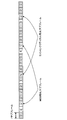
- FIG. 1 is a diagram illustrating an example of providing different services for each subframe in TDD.
- a subframe configuration of a predetermined period (20 subframes) in a wireless communication system that provides MBB and mission critical is shown.
- FIG. 1 shows an example of a TDD configuration (TDD Config. 2) including two UL subframes out of 10 subframes.
- TDD Config. 2 For example, consider a case where the UL of subframe # 2 in each radio frame is for MBB and the UL of subframe # 7 is for mission critical. Thus, if the UL subframe allocation is divided between MBB and mission critical, the UL throughputs of both services are reduced to 50%.
- the throughput is not important, so the deterioration of service quality is not obvious.
- the throughput is important, so the deterioration of service quality becomes a problem.
- the present inventors have conceived to allow a predetermined UE to transmit and receive a plurality of TBs in 1 TTI. And the control method of UE / eNB for implement
- a plurality of TBs are described as being allocated (transmitted and / or received) in the same CC (cell), the same layer, and the same TTI, but the application of the present invention is not limited to this.
- the present invention is applicable even if at least one of CC, layer, and TTI is different.
- the eNB assigns a plurality of TBs allocated to the same TTI to a plurality of L1 / L2 control signals (for example, DCI (Downlink Control Information) including information (scheduling information) corresponding to different TBs. Scheduling)).
- the plurality of DCIs may be configured in different DCI formats, or may be configured in the same DCI format.
- the plurality of DCIs may be called, for example, UL grant (uplink grant), DL assignment (downlink assignment), and the like.
- the UE schedules multiple TBs received in the same layer of the same CC, blindly detects multiple DCIs, and controls transmission / reception processing of multiple TBs based on the detected multiple DCIs.
- the UE determines a TB to which each DCI is related by using an identifier (for example, RNTI (Radio Network Temporary Identifier)), a payload size (bit length, TB size), a predetermined field, or a combination thereof. be able to.
- RNTI Radio Network Temporary Identifier
- a plurality of DCIs may be masked with different (different) RNTIs for each TB.
- the RNTI may be an RNTI (for example, C-RNTI (Cell RNTI)) used in an existing LTE system, or may be a newly defined RNTI, for example, a TB-RNTI (Transport It may also be called Block Radio Network Temporary Identifier.
- the UE attempts multiple DCI format detections with the same payload size but different RNTIs, and if not configured, a single RNTI Attempt to detect DCI format masked with
- the plurality of RNTIs may have different lengths, for example, the first RNTI may be 16 bits long and the second RNTI may be 24 bits long.
- the UE may report the number of RNTI bits that it supports (available) in advance to the base station as terminal capability information (UE capability).
- the plurality of DCIs may have different (different) payload sizes for each TB.
- each DCI format can be detected by trial of blind detection with each payload size, it is not necessary to use two RNTIs that have only a finite number. For this reason, more UEs can be scheduled.
- the UE attempts to detect multiple DCI formats with different payload lengths masked with the same RNTI if detection of multiple DCI formats with different payloads is configured, and assumes a single payload if not configured Then, DCI format detection is attempted.
- the plurality of DCIs may include a field indicating TB to be scheduled.
- a field indicating TB to be scheduled In this case, if each DCI format has the same payload size, an increase in the number of blind detection trials can be suppressed. Furthermore, if the same RNTI is assigned to each DCI format, it is not necessary to use only two RNTIs.
- information indicating which TB corresponds to each value of a specific bit field included in DCI may be notified to the UE in advance by higher layer signaling or the like.
- the UE performs a blind detection trial of DCI assuming a specific payload size, and confirms the value of the specific bit field for the DCI that has been successfully descrambled by CRC (Cyclic Redundancy Check). Then, TB data corresponding to a preset value of the bit field is transmitted / received.
- each TB's MAC CE Medium Access Control Control Element
- TB # 0 from the smaller TB payload. This can be realized by assigning numbers in ascending order of TB # 1,. If (1), the UE can appropriately identify which DCI corresponds to which TB when decoding is completed. If it is (2), it is possible to identify which DCI corresponds to which TB without consuming the data payload because it is specified by MAC CE. In (3), the overhead for notifying the correspondence between DCI and TB can be made zero.
- the field indicating the TB to be scheduled may be a new bit field that is not defined in the conventional LTE / LTE-A system, or may be an existing bit field.
- a CIF Carrier Indicator Field
- a specific value of CIF for example, “01” may be a value indicating TB1
- another value for example, “10” may be a value indicating TB2. Note that fields other than CIF may be read and used.
- the UE may be notified in advance by higher layer signaling (for example, RRC signaling, broadcast information, etc.) that a plurality of TBs are transmitted and / or received in the same layer of the same CC of the same TTI. You may recognize (for example, you may judge by notification of another information).
- higher layer signaling for example, RRC signaling, broadcast information, etc.
- the UE may be notified in advance of higher layer signaling (for example, RRC signaling, broadcast information, etc.) of settings necessary for transmitting and / or receiving a plurality of TBs in the same layer of the same CC of the same TTI. It may be recognized in advance (for example, it may be determined by notification of other information).
- the necessary setting may be, for example, information on the correspondence between RNTI and TB, information on the correspondence between payload size and TB, information on the correspondence between fields included in DCI and TB, and the like. .
- LA is applied to each TB, and resource (for example, PRB (Physical Resource Block)) allocation is performed separately.
- resource for example, PRB (Physical Resource Block)
- the first embodiment is further classified into two.
- the resource mapping rule refers to a rule for determining parameters (TTI length, number of subcarriers, number of PRBs, etc.) used for resource allocation, for example.
- the same (or similar) resource mapping rule as that of the existing LTE is applied to all TBs.
- all TBs like existing LTE, have a minimum of 1 PRB in DwPTS (Downlink Pilot Time Slot) included in 1 ms TTI (DL subframe) and / or 1 ms TTI (special subframe) It is mapped (scheduled) as a unit.
- DwPTS Downlink Pilot Time Slot
- Each TB is demodulated based on a reference signal such as CRS (Cell-specific Reference Signal) or DMRS (DeModulation Reference Signal). Note that which reference signal is used can be determined based on a transmission mode.
- CRS Cell-specific Reference Signal
- DMRS DeModulation Reference Signal
- Priority may be defined for each TB.
- the UE and / or the eNB may perform control so that the higher priority TB is transmitted and / or received with priority (for example, as it is). Further, the lower priority TB may be controlled to drop, puncture or rate match.
- the priority of the TB may be defined (determined) according to the higher layer setting information of each TB, or may be set separately by higher layer signaling.
- a bearer type for example, a bearer for voice communication or a bearer for data communication
- a service type provided by the TB for example, MBB, IoT
- the service type may be referred to as a TB type.
- the above-mentioned predetermined condition for applying drop, puncture or rate matching may be, for example, a condition regarding TB resource, transmission power, size, etc., and may be any of the following: (1) Both TBs If resource (PRB) allocations overlap, (2) the total transmission power allocated to both TBs exceeds the maximum allowable transmission power of the CC, (3) the total TB size of both TBs is the UE's When the soft buffer capacity is exceeded.
- the predetermined conditions are not limited to these.
- FIG. 2 is a diagram illustrating an example of resource allocation of a plurality of TBs in the method 1 of the first embodiment.
- FIG. 2 shows an example in which some resource allocations of TB1 and TB2 having a lower priority than TB1 overlap in a certain TTI.
- Each TB may be configured with an arbitrary subband width (for example, an arbitrary number of PRBs), and each TB may have a different subband width or the same subband width.
- a case where a low priority TB2 is dropped (FIG. 2A) and a case where a low priority TB2 is punctured or rate matched (FIG. 2B) are: Each is shown.
- the UE determines whether or not the scheduling results of a plurality of TBs overlap, and in the case of overlap, the UE additionally processes a TB having a low priority. In the case of FIG. 2A (drop), transmission or reception of a low priority TB is stopped. In the case of FIG.
- a resource mapping rule different from the existing LTE is applied to at least one TB. That is, a different resource mapping rule may be used for each TB.
- a TB to which a resource mapping rule different from that of existing LTE is applied may be demodulated based on CRS or DMRS as in the case of existing LTE, or demodulated based on a signal different from these reference signals. Also good. Note that which signal to use can be determined based on, for example, the transmission mode.
- mapping that increases the amount of data resources is applied to a TB for large capacity and / or high speed communication, and an RS (reference signal) resource is applied to a TB for low delay and / or high reliability.
- RS reference signal
- a rule that applies mapping that increases the amount of data may be adopted. Further, in this rule, the length of the data transmission section (TTI) for a predetermined TB may be different from the existing LTE TTI.
- the UE and / or eNB gives priority to the higher priority TB under a predetermined condition (for example, as it is). You may control to transmit. In this case, the lower priority TB may be controlled to drop, puncture, or rate match.
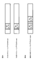
- FIG. 3 is a diagram illustrating an example of resource allocation of a plurality of TBs in the method 2 according to the first embodiment.
- TB1 has a TTI shorter than TB2, but the same example as FIG. 2 is shown except for this point.
- FIG. 3A when resource allocation of a plurality of TBs overlaps, there is a case where TB2 having a low priority is dropped (FIG. 3A) and a case where TB2 having a low priority is punctured or rate matched (FIG. 3B). Each is shown.
- the TTI When using a resource mapping rule with a different data transmission interval (TTI) length, for example, for a large capacity and / or high-speed communication TB, the TTI is increased to increase the amount of resources, and a low delay and / or high reliability TB is used. In this case, the delay of demodulation and decoding can be shortened by shortening the TTI. Furthermore, if the priority of the large capacity TB is set lower and the lower one is punctured or rate matched, the impact on the low delay TB when puncturing or rate matching occurs can be suppressed to a low level. .
- TTI data transmission interval
- information for example, TTI length, number of subcarriers, etc.
- the UE may update the resource mapping rule of a predetermined TB based on the information.
- a PUSCH / PDSCH in 1 TTI that is separately allocated to a plurality of UEs in a conventional LTE system can be assigned to one UE. It can be controlled to transmit and receive. Thereby, a plurality of services can be provided simultaneously with appropriate communication quality.
- ⁇ Second Embodiment Scheduling a plurality of TBs with one DCI>
- the eNB schedules a plurality of TBs allocated to the same TTI with one DCI including a plurality of pieces of information corresponding to different TBs. That is, the DCI includes scheduling information for each TB.
- the UE blindly detects one DCI that schedules a plurality of TBs received in the same layer of the same CC, and controls transmission / reception processing of the plurality of TBs based on the detected one DCI.
- the same resource mapping rule may be applied to a plurality of TBs, or different resource mapping rules may be applied.
- a predetermined TB may be mapped in a form embedded in a resource of another TB.
- a resource of a predetermined TB may be mapped so as to be sandwiched on another TB resource on the frequency and / or time axis, or distributed to another TB resource on the frequency and / or time axis. May be mapped.
- a resource of a predetermined TB may be mapped so as to protrude from a resource of another TB.
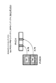
- FIG. 4 is a diagram illustrating an example of resource allocation of a plurality of TBs in the second embodiment.
- the resource of TB2 is mapped to be embedded on the resource of TB1 on the time axis in the same subband as the resource of TB1.
- resource mapping for TB1 having a large resource is instructed by DCI for scheduling TB1 and TB2. Further, the DCI is notified of information indicating which range of resources for TB1 is mapped to TB2.
- the DCI may include information on the start symbol position of the resource for TB2, the start PRB index, the bandwidth of the resource for TB2, and the like.
- information about LA may be different, and information about LA of each TB may be included in DCI.
- the information related to the LA of one TB may be composed of difference information based on information related to the other LA.
- the resource of TB2 may protrude from the resource region of TB1 (for example, the time and / or frequency region). Furthermore, the resource of TB2 may be smaller than the resource region (eg, time and / or frequency region) of TB1.
- the second embodiment by scheduling a plurality of TBs with one DCI, it is possible to simultaneously provide a plurality of services with appropriate communication quality while suppressing the complexity of blind detection.
- Downlink HARQ> As described in the first and second embodiments described above, the present inventors separately perform scheduling for the same TTI when different LAs are performed for a plurality of TBs. It was found that it is desirable to perform HARQ control. Downlink HARQ control will be described in a third embodiment, and uplink HARQ control will be described in a fourth embodiment described later.
- the third embodiment relates to downlink HARQ control. Specifically, in the third embodiment, the UE generates respective HARQ-ACK (Acknowledgement) bits for reception of PDSCH corresponding to a plurality of TBs, and uses an uplink channel (for example, PUCCH / PUSCH). provide feedback.
- HARQ-ACK Acknowledgement
- the UE may perform feedback based on the HARQ-ACK feedback method for multiple ranks when MIMO (Multi Input Multi Output) is applied in the existing LTE system.
- MIMO Multi Input Multi Output
- QPSK Quadrature Phase Shift Keying
- the UE may perform feedback based on the HARQ-ACK feedback method for multiple CCs when carrier aggregation (CA) is applied in the existing LTE system.
- CA carrier aggregation
- the UE transmits HARQ-ACK of each TB to PUCCH format 1b + channel selection, PUCCH format 3, Rel. 13 Transmit in the new PUCCH format specified by CA or PUSCH.
- the new PUCCH format is a PUCCH format with a large number of bits that can be transmitted, and may be called PUCCH format 4, large-capacity PUCCH format, extended PUCCH format, new format, or the like.
- the new PUCCH format is configured to be able to store HARQ-ACK having a predetermined number of bits (for example, 128 bits) or more at maximum.
- FIG. 5 is a diagram illustrating an example of resources for downlink HARQ feedback in the third embodiment.
- 5A and 5B show a case where downlink HARQ feedback is performed on PUCCH and a case where PUSCH is performed on PUSCH, respectively.
- two TBs (TB1, TB2) are scheduled by one or two DCIs (DL assignments).
- the A / N (ACK / NACK) of TB1 and the A / N of TB2 are transmitted using any of the PUCCH formats described above.
- the A / N of TB1 and the A / N of TB2 are transmitted using resources separately designated by the UL grant.
- there is one uplink TB and a PUSCH that transmits a plurality of A / Ns is specified by one UL grant.
- TPC Transmit Power Control
- TPC field TPC command bits included in each DCI can be used as follows. : (1) TPC command bits included in DCI for assigning specific TB of PCell (Primary Cell) are used for power control of PUCCH, (2) TPC commands included in DCI for assigning TB other than specific TB of PCell The bit is interpreted and used as an ARI (ACK / NACK Resource Indicator) in the same manner as the TPC command bit included in the DCI for assigning the TB of the SCell (Secondary Cell).
- ARI ACK / NACK Resource Indicator
- a TPC command bit (TPC field) included in the DCI may be used as a TPC command of PUCCH.
- the PUCCH resource may be determined based on information (ARI) separately included in the DCI, or may be determined based on information separately notified by higher layer signaling.
- the UE can multiplex UCI (Uplink Control Information) such as HARQ-ACK, SR (Scheduling Request), CSI (Channel State Information), etc. into multiple TBs. It is also possible to multiplex only one TB. This will be described with reference to FIG.
- FIG. 6 is a diagram illustrating an example of A / N multiplexing of downlink HARQ feedback in the third embodiment.
- FIG. 6 shows an example of HARQ feedback using PUSCH similar to FIG. 5B, but there are also two upstream TBs, and a plurality of PUSCHs are scheduled by one or a plurality of UL grants. The point is different.
- both the A / N of TB1 and the A / N of TB2 are included in each PUSCH corresponding to a plurality of TBs and transmitted.
- UCI when UCI is multiplexed on a plurality of TBs, for example, it can be multiplexed on two sequences with different LA, so that a diversity effect can be obtained.
- both the A / N of TB1 and the A / N of TB2 are included in the PUSCH corresponding to one TB (TB2 in FIG. 6B) and transmitted.
- the quality of the uplink signal (for example, the quality of mission critical data) can be maintained. It should be noted that to which TB the UCI is multiplexed can be determined according to a predetermined rule, and may be determined according to the priority of the TB as shown in the first embodiment, for example.
- the fourth embodiment relates to uplink HARQ control. Specifically, in the fourth embodiment, the eNB performs a physical hybrid-ARQ indicator channel (PHICH) or a physical downlink control channel (PDCCH) / EPDCCH (enhanced PDCCH) for uplink data transmitted from each UE on the TB. ) Instruct the retransmission / new data transmission of each TB.
- PHICH physical hybrid-ARQ indicator channel
- PDCCH physical downlink control channel
- EPDCCH enhanced PDCCH
- the UE may receive the HARQ-ACK bit for each TB by PHICH.
- the PHICH resource is determined by the data allocation resource (and the DMRS sequence index), as shown in the second embodiment, the allocation of a predetermined TB resource embedded in another TB resource has been performed. In this case, PHICH resources will collide between both TBs.
- the PHICH resource that receives the HARQ-ACK bit of a predetermined TB may be calculated by adding a predetermined offset to the conventional PHICH resource calculation formula.
- FIG. 7 is a diagram illustrating an example of a PHICH resource for uplink HARQ feedback in the fourth embodiment.
- FIG. 7 shows an example in which the eNB transmits two HARQ-ACKs with PHICH resources for the PUSCHs of two TBs (TB1, TB2).
- the PHICH resource (index) is obtained by a function of the TB index in addition to the PUCSH PRB number (index) and DMRS index.
- the TB index is a number unique to each TB. For example, TB1 is ‘1’ and TB2 is ‘2’.
- Information on the TB index of a predetermined TB may be notified by DCI instructing scheduling of the TB or may be notified by higher layer signaling.
- the UE may receive a retransmission / new data instruction for each TB on the PDCCH / EPDCCH.
- FIG. 8 is a diagram illustrating an example of a configuration of DCI in the fourth embodiment.
- each DCI when a plurality of DCIs allocate different TBs, each DCI includes an NDI (New Data Indicator) indicating whether the corresponding TB allocation is retransmission data or new data. May be.
- the DCI (UL grant) for scheduling TB1 includes the NDI for the PUSCH of TB1
- the DCI (UL grant) for scheduling TB2 includes the NDI for the PUSCH of TB2.
- the DCI when a plurality of TBs are allocated by one DCI, the DCI includes NDIs indicating whether the TB allocation is retransmission data or new data by the number of the plurality of TBs. May be. That is, different bit fields included in DCI indicate NDIs of different TBs.
- the DCI that schedules TB1 and TB2 includes the NDI for the PUSCH of TB1 and the NDI for the PUSCH of TB2.
- HARQ feedback is not limited to the above-described transmission of PHICH and PDCCH / EPDCCH, and both may be used.
- uplink HARQ control of each TB can be appropriately performed even when a plurality of TBs are transmitted and received in a predetermined period.
- the fifth embodiment relates to uplink TPC control. Specifically, in the fifth embodiment, the eNB notifies the TPC command of each TB for the PUSCH that the UE transmits on each TB, and the UE performs transmission power control of each TB on the corresponding TPC command. To implement.
- FIG. 9 is a diagram showing an example of the configuration of DCI in the fifth embodiment.
- each DCI may include a TPC command bit for the corresponding TB assignment.
- the UE performs transmission power control using a TPC command included in each DCI.
- DCI (UL grant) for scheduling TB1 includes a TPC for the PUSCH of TB1
- DCI (UL grant) for scheduling TB2 includes a TPC for the PUSCH of TB2.
- the DCI may include the TPC for the TB allocation by the number of the plurality of TBs. That is, different bit fields included in DCI indicate TPCs of different TBs.
- the DCI that schedules TB1 and TB2 includes the TPC for the PUSCH of TB1 and the TPC for the PUSCH of TB2.
- the UE may obtain a PHR (Power Headroom Report) to be notified to the eNB based on one TB or may be obtained based on two or more TBs. It may be obtained in consideration of all TBs. Since the eNB knows all the TB allocations, it may be sufficient to calculate based on one TB.
- PHR Power Headroom Report
- the TB used for calculating the PHR may be selected based on, for example, any of the following or a combination thereof: (1) the size of the TB, (2) the size of the transmission power, and (3) the TB type. .
- (1) since a large size TB is likely to have a larger transmission power, the surplus power can be accurately grasped by obtaining the PHR from the large size TB.
- (2) the surplus power can be accurately grasped by obtaining the PHR with the TB having a large transmission power.
- quality assurance becomes easy by obtaining PHR in TB (for example, mission critical) where quality assurance is more important.
- the uplink TPC of each TB can be appropriately controlled even when a plurality of TBs are transmitted and received in a predetermined period.
- ⁇ Modification> In each of the above-described embodiments, the configuration in which a plurality of TBs are transmitted and received in 1 TTI (1 subframe) as the predetermined period is shown, but the application of the present invention is not limited to this.
- the present invention is applied even when a period shorter than 1 TTI (short TTI) in an existing LTE system is used as a TTI or a period longer than 1 TTI (super subframe) is used as a TTI.
- a plurality of TBs may be transmitted / received in a shorter / longer period than the existing TTI (subframe).
- the number of TB transmitted / received in a predetermined period may be 2 or more arbitrary numbers.
- a data channel for example, PDSCH / PUSCH
- a control channel for example, PDCCH / EPDCCH
- DCI that schedules the TB.
- Shorte subframe scheduling may be assigned to different subframes (cross subframe scheduling).
- a plurality of DCIs that schedule a TB may be detected with the same TTI or may be detected with different TTIs.
- the LA applied on the upstream and downstream may be the same or different.
- an MBB LA and an IoT LA may be set in two downstream TBs, or an MBB LA and an IoT LA may be set in the upstream TB, or the MBB A LA for mission may be set, or a LA for mission critical may be set.
- the UE may notify the eNB of terminal capability information (UE capability) indicating that a plurality of TBs can be transmitted and / or received by the same CC, the same layer, and the same TTI.
- UE capability terminal capability information
- eNB is good also as a structure which implements the control which concerns on the above-mentioned embodiment with respect to the user terminal which has notified the said terminal capability information.
- wireless communication system Wireless communication system
- the wireless communication method according to each of the above-described embodiments (including modifications) of the present invention is applied.
- wireless communication method which concerns on each said embodiment may be applied independently, respectively, and may be applied in combination.
- FIG. 10 is a diagram illustrating an example of a schematic configuration of a wireless communication system according to an embodiment of the present invention.
- carrier aggregation (CA) and / or dual connectivity (DC) in which a plurality of basic frequency blocks (component carriers) each having a system bandwidth (for example, 20 MHz) of the LTE system as one unit are applied.
- the wireless communication system 1 may be referred to as SUPER 3G, LTE-A (LTE-Advanced), IMT-Advanced, 4G, 5G, FRA (Future Radio Access), or the like.
- a radio communication system 1 shown in FIG. 10 includes a radio base station 11 that forms a macro cell C1 having a relatively wide coverage, and a radio base station 12 (12a) that is arranged in the macro cell C1 and forms a small cell C2 that is narrower than the macro cell C1. -12c). Moreover, the user terminal 20 is arrange
- the user terminal 20 can be connected to both the radio base station 11 and the radio base station 12. It is assumed that the user terminal 20 uses the macro cell C1 and the small cell C2 simultaneously by CA or DC. Moreover, the user terminal 20 may apply CA or DC using a plurality of cells (CC) (for example, 5 or less CCs, 6 or more CCs).
- CC cells
- Communication between the user terminal 20 and the radio base station 11 can be performed using a carrier having a relatively low frequency band (for example, 2 GHz) and a narrow bandwidth (referred to as an existing carrier or a legacy carrier).
- a carrier having a relatively high frequency band for example, 3.5 GHz, 5 GHz, etc.
- the same carrier may be used.
- the configuration of the frequency band used by each radio base station is not limited to this.
- a wired connection for example, an optical fiber compliant with CPRI (Common Public Radio Interface), an X2 interface, etc.
- a wireless connection It can be set as the structure to do.
- the radio base station 11 and each radio base station 12 are connected to the higher station apparatus 30 and connected to the core network 40 via the higher station apparatus 30.
- the upper station device 30 includes, for example, an access gateway device, a radio network controller (RNC), a mobility management entity (MME), and the like, but is not limited thereto.
- RNC radio network controller
- MME mobility management entity
- Each radio base station 12 may be connected to the higher station apparatus 30 via the radio base station 11.
- the radio base station 11 is a radio base station having a relatively wide coverage, and may be called a macro base station, an aggregation node, an eNB (eNodeB), a transmission / reception point, or the like.
- the radio base station 12 is a radio base station having local coverage, and includes a small base station, a micro base station, a pico base station, a femto base station, a HeNB (Home eNodeB), an RRH (Remote Radio Head), and transmission / reception. It may be called a point.
- the radio base stations 11 and 12 are not distinguished, they are collectively referred to as a radio base station 10.
- Each user terminal 20 is a terminal compatible with various communication methods such as LTE and LTE-A, and may include not only a mobile communication terminal but also a fixed communication terminal.
- OFDMA orthogonal frequency division multiple access
- SC-FDMA single carrier-frequency division multiple access
- OFDMA is a multi-carrier transmission scheme that performs communication by dividing a frequency band into a plurality of narrow frequency bands (subcarriers) and mapping data to each subcarrier.
- SC-FDMA is a single-carrier transmission scheme that reduces interference between terminals by dividing the system bandwidth into bands consisting of one or continuous resource blocks for each terminal and using a plurality of terminals with mutually different bands. is there.
- the uplink and downlink radio access methods are not limited to these combinations.
- downlink channels include a downlink shared channel (PDSCH) shared by each user terminal 20, a broadcast channel (PBCH: Physical Broadcast Channel), a downlink L1 / L2 control channel, and the like. Used. User data, higher layer control information, SIB (System Information Block), etc. are transmitted by PDSCH. Also, MIB (Master Information Block) is transmitted by PBCH.
- PDSCH downlink shared channel
- PBCH Physical Broadcast Channel
- SIB System Information Block
- MIB Master Information Block
- Downlink L1 / L2 control channels include PDCCH (Physical Downlink Control Channel), EPDCCH (Enhanced Physical Downlink Control Channel), PCFICH (Physical Control Format Indicator Channel), PHICH (Physical Hybrid-ARQ Indicator Channel), and the like.
- Downlink control information (DCI: Downlink Control Information) including scheduling information of PDSCH and PUSCH is transmitted by PDCCH.
- the number of OFDM symbols used for PDCCH is transmitted by PCFICH.
- the HAICH transmission confirmation signal (ACK / NACK) for PUSCH is transmitted by PHICH.
- EPDCCH is frequency-division multiplexed with PDSCH (downlink shared data channel), and is used for transmission of DCI and the like in the same manner as PDCCH.
- an uplink shared channel (PUSCH) shared by each user terminal 20, an uplink control channel (PUCCH: Physical Uplink Control Channel), a random access channel (PRACH: Physical Random Access Channel) is used.
- PUSCH uplink shared channel
- PUCCH Physical Uplink Control Channel
- PRACH Physical Random Access Channel
- User data and higher layer control information are transmitted by PUSCH.
- downlink radio quality information CQI: Channel Quality Indicator
- ACK / NACK delivery confirmation signal
- a random access preamble for establishing connection with a cell is transmitted by the PRACH.
- a cell-specific reference signal CRS
- CSI-RS channel state information reference signal
- DMRS Demodulation Reference Signal
- a measurement reference signal SRS: Sounding Reference Signal
- a demodulation reference signal DMRS: DeModulation Reference Signal
- the DMRS may be referred to as a user terminal specific reference signal (UE-specific Reference Signal). Further, the transmitted reference signal is not limited to these.
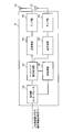
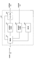
- FIG. 11 is a diagram illustrating an example of the overall configuration of a radio base station according to an embodiment of the present invention.
- the radio base station 10 includes a plurality of transmission / reception antennas 101, an amplifier unit 102, a transmission / reception unit 103, a baseband signal processing unit 104, a call processing unit 105, and a transmission path interface 106.
- the transmission / reception antenna 101, the amplifier unit 102, and the transmission / reception unit 103 may each be configured to include one or more.
- User data transmitted from the radio base station 10 to the user terminal 20 via the downlink is input from the higher station apparatus 30 to the baseband signal processing unit 104 via the transmission path interface 106.
- PDCP Packet Data Convergence Protocol
- RLC Radio Link Control
- MAC Medium Access
- Retransmission control for example, HARQ (Hybrid Automatic Repeat reQuest) transmission processing
- HARQ Hybrid Automatic Repeat reQuest
- the downlink control signal is also subjected to transmission processing such as channel coding and inverse fast Fourier transform, and is transferred to the transmission / reception unit 103.
- the transmission / reception unit 103 converts the baseband signal output by precoding for each antenna from the baseband signal processing unit 104 to a radio frequency band and transmits the converted signal.
- the radio frequency signal frequency-converted by the transmission / reception unit 103 is amplified by the amplifier unit 102 and transmitted from the transmission / reception antenna 101.
- the transmission / reception unit 103 can be configured by a transmitter / receiver, a transmission / reception circuit, or a transmission / reception device which is described based on common recognition in the technical field according to the present invention.
- the transmission / reception part 103 may be comprised as an integral transmission / reception part, and may be comprised from a transmission part and a receiving part.
- the radio frequency signal received by the transmission / reception antenna 101 is amplified by the amplifier unit 102.
- the transmission / reception unit 103 receives the uplink signal amplified by the amplifier unit 102.
- the transmission / reception unit 103 converts the frequency of the received signal into a baseband signal and outputs it to the baseband signal processing unit 104.
- the baseband signal processing unit 104 performs fast Fourier transform (FFT) processing, inverse discrete Fourier transform (IDFT: Inverse Discrete Fourier Transform) processing, and error correction on user data included in the input upstream signal.
- FFT fast Fourier transform
- IDFT inverse discrete Fourier transform
- Decoding, MAC retransmission control reception processing, RLC layer and PDCP layer reception processing are performed and transferred to the upper station apparatus 30 via the transmission path interface 106.
- the call processing unit 105 performs call processing such as communication channel setting and release, state management of the radio base station 10, and radio resource management.
- the transmission path interface 106 transmits and receives signals to and from the higher station apparatus 30 via a predetermined interface.
- the transmission path interface 106 transmits / receives signals (backhaul signaling) to / from other radio base stations 10 via an interface between base stations (for example, an optical fiber compliant with CPRI (Common Public Radio Interface), X2 interface). May be.
- CPRI Common Public Radio Interface
- X2 interface May be.
- the transmission / reception unit 103 transmits DCI related to transmission and / or reception of a plurality of TBs to the user terminal 20.
- the plurality of TBs correspond to, for example, TBs assigned to the same CC, the same layer, and the same TTI.
- the transmission / reception unit 103 may transmit a plurality of DCIs including information corresponding to different TBs as DCI, or may transmit one DCI including a plurality of information corresponding to different TBs. Good.
- the transmission / reception unit 103 may transmit instruction information (DL assignment) for reception of a downlink shared channel (PDSCH) corresponding to a plurality of TBs. Moreover, the transmission / reception part 103 may transmit the instruction
- the transmission / reception unit 103 may transmit a plurality of TBs (PDSCH) assigned by the above-described DCI. Further, the transmission / reception unit 103 may transmit HARQ-ACK for a plurality of TBs (PUSCH) allocated by DCI.
- PDSCH a plurality of TBs assigned by the above-described DCI.
- PUSCH a plurality of TBs allocated by DCI.
- the transmission / reception unit 103 may transmit a notification that a plurality of TBs are transmitted and / or received in a predetermined CC, layer, and subframe. Furthermore, you may transmit the setting information required for the said transmission and / or reception.
- the transmission / reception unit 103 includes information on priority of a predetermined TB, information on resource mapping rules of the predetermined TB (for example, TTI length, number of subcarriers, etc.), PUCCH resource for the predetermined TB (for example, PUCCH resource for HARQ) Information regarding the information, information regarding the TB index of a predetermined TB, and the like may be notified.
- information on resource mapping rules of the predetermined TB for example, TTI length, number of subcarriers, etc.
- PUCCH resource for the predetermined TB for example, PUCCH resource for HARQ
- the transmission / reception unit 103 receives a plurality of TBs transmitted from the user terminal 20 based on the above-described DCI.
- the transmission / reception unit 103 may receive HARQ-ACK for a plurality of TBs (PDSCHs) transmitted based on DCI.
- the transmission / reception unit 103 may receive the PHR.
- FIG. 12 is a diagram illustrating an example of a functional configuration of a radio base station according to an embodiment of the present invention. Note that FIG. 12 mainly shows functional blocks of characteristic portions in the present embodiment, and the wireless base station 10 also has other functional blocks necessary for wireless communication. As illustrated in FIG. 12, the baseband signal processing unit 104 includes at least a control unit (scheduler) 301, a transmission signal generation unit 302, a mapping unit 303, a reception signal processing unit 304, and a measurement unit 305. ing.
- the baseband signal processing unit 104 includes at least a control unit (scheduler) 301, a transmission signal generation unit 302, a mapping unit 303, a reception signal processing unit 304, and a measurement unit 305. ing.
- the control unit (scheduler) 301 controls the entire radio base station 10.
- the control part 301 can be comprised from the controller, the control circuit, or control apparatus demonstrated based on the common recognition in the technical field which concerns on this invention.
- the control unit 301 controls signal generation by the transmission signal generation unit 302 and signal allocation by the mapping unit 303, for example.
- the control unit 301 also controls signal reception processing by the reception signal processing unit 304 and signal measurement by the measurement unit 305.
- the control unit 301 controls scheduling (for example, resource allocation) of system information, a downlink data signal transmitted on the PDSCH, and a downlink control signal transmitted on the PDCCH and / or EPDCCH. It also controls scheduling of synchronization signals (PSS (Primary Synchronization Signal) / SSS (Secondary Synchronization Signal)) and downlink reference signals such as CRS, CSI-RS, and DMRS.
- PSS Primary Synchronization Signal
- SSS Secondary Synchronization Signal
- the control unit 301 also transmits an uplink data signal transmitted on the PUSCH, an uplink control signal transmitted on the PUCCH and / or PUSCH (for example, a delivery confirmation signal (HARQ-ACK)), a random access preamble transmitted on the PRACH, Controls scheduling of uplink reference signals and the like.
- an uplink data signal transmitted on the PUSCH for example, an uplink control signal transmitted on the PUCCH and / or PUSCH (for example, a delivery confirmation signal (HARQ-ACK)), a random access preamble transmitted on the PRACH, Controls scheduling of uplink reference signals and the like.
- HARQ-ACK delivery confirmation signal
- the control unit 301 controls to transmit and / or receive a plurality of TBs having at least one of CC, layer, and TTI.
- the plurality of TBs may be a plurality of TBs in which at least two of CC, layer, and TTI are the same, or may be a plurality of TBs in which all of CC, layer, and TTI are the same.
- the control unit 301 may apply the same resource mapping rule to a plurality of TBs, or may apply different resource mapping rules.
- control unit 301 may perform control so that a higher priority TB is preferentially allocated (for example, maintaining resources and / or transmission power). Further, the control unit 301 may perform control such that a lower priority TB is dropped, punctured, or rate matched.
- the control unit 301 controls scheduling of PDSCH / PUSCH corresponding to a plurality of TBs, and indicates instruction information (DCI) for instructing radio resources used in each PDSCH / PUSCH by a predetermined user terminal 20 using PDCCH / EPDCCH.
- the transmission signal generation unit 302 and the mapping unit 303 are controlled so as to transmit to each other.
- the control unit 301 controls the received signal processing unit 304 to monitor PUSCH resources corresponding to a plurality of TBs notified by DCI.
- the control unit 301 may control to transmit a plurality of DCIs including information corresponding to different TBs as the DCI (first embodiment), or may include a plurality of information corresponding to different TBs. You may control to transmit one DCI (2nd Embodiment).
- the control unit 301 may control a plurality of DCIs to be masked with different (different) RNTIs, may be controlled to have different (different) payload sizes, or may be a scheduling target. You may control to include the field which shows TB.
- control unit 301 may control HARQ processing of a plurality of TBs for each TB (third and fourth embodiments). For example, the control unit 301 manages the HARQ process of each TB separately.
- the control unit 301 determines whether or not the downlink data needs to be retransmitted for the predetermined TB, and if necessary, retransmits the data. Control is performed to perform processing (third embodiment). Further, the control unit 301 may perform control so that uplink data retransmission / new data instruction for each TB is transmitted by either PHICH or PDCCH / EPDCCH (fourth embodiment).
- control unit 301 controls the uplink transmission power of a plurality of TBs for each TB (fifth embodiment). For example, the control unit 301 performs control so that TPC commands for each TB are generated separately and included in the scheduling DCI and notified to the user terminal 20.
- the control unit 301 when the PHR is input from the reception signal processing unit 304, the control unit 301 performs power control of each TB based on the PHR. For example, the control unit 301 determines that the PHR is calculated based on one TB, obtains excess transmission power of a predetermined user terminal 20 from the PHR, and performs the same TTI as the TB and / or the TB. You may control the uplink transmission power of the other TB transmitted in the.
- control unit 301 notifies that a plurality of TBs are transmitted and / or received in a predetermined CC, layer, and subframe, setting information necessary for the transmission and / or reception, information on the priority of the predetermined TB, Information about resource mapping rules for a given TB, information about PUCCH resources for a given TB, information about a TB index for a given TB, etc. using higher layer signaling (for example, RRC signaling), DCI or a combination thereof, etc. You may control to notify the terminal 20.
- higher layer signaling for example, RRC signaling
- the transmission signal generation unit 302 generates a downlink signal (downlink control signal, downlink data signal, downlink reference signal, etc.) based on an instruction from the control unit 301, and outputs it to the mapping unit 303.
- the transmission signal generation unit 302 can be configured by a signal generator, a signal generation circuit, or a signal generation device described based on common recognition in the technical field according to the present invention.
- the transmission signal generation unit 302 generates, for example, a DL assignment that notifies downlink signal allocation information and a UL grant that notifies uplink signal allocation information based on an instruction from the control unit 301.
- the downlink data signal is subjected to coding processing and modulation processing according to a coding rate, a modulation scheme, and the like determined based on channel state information (CSI: Channel State Information) from each user terminal 20.
- CSI Channel State Information
- the mapping unit 303 maps the downlink signal generated by the transmission signal generation unit 302 to a predetermined radio resource based on an instruction from the control unit 301, and outputs it to the transmission / reception unit 103.
- the mapping unit 303 can be configured by a mapper, a mapping circuit, or a mapping device described based on common recognition in the technical field according to the present invention.
- the reception signal processing unit 304 performs reception processing (for example, demapping, demodulation, decoding, etc.) on the reception signal input from the transmission / reception unit 103.
- the received signal is, for example, an uplink signal (uplink control signal, uplink data signal, uplink reference signal, etc.) transmitted from the user terminal 20.
- the reception signal processing unit 304 can be configured by a signal processor, a signal processing circuit, or a signal processing device described based on common recognition in the technical field according to the present invention.
- the reception signal processing unit 304 outputs the information decoded by the reception processing to the control unit 301. For example, when receiving PUCCH including HARQ-ACK, HARQ-ACK is output to control section 301.
- the reception signal processing unit 304 outputs the reception signal and the signal after reception processing to the measurement unit 305.
- the measurement unit 305 performs measurement on the received signal.
- the measurement part 305 can be comprised from the measuring device, measurement circuit, or measurement apparatus demonstrated based on common recognition in the technical field which concerns on this invention.
- the measurement unit 305 may measure, for example, received power (for example, RSRP (Reference Signal Received Power)), reception quality (for example, RSRQ (Reference Signal Received Quality)), channel state, and the like of the received signal.
- the measurement result may be output to the control unit 301.
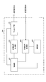
- FIG. 13 is a diagram illustrating an example of the overall configuration of a user terminal according to an embodiment of the present invention.
- the user terminal 20 includes a plurality of transmission / reception antennas 201, an amplifier unit 202, a transmission / reception unit 203, a baseband signal processing unit 204, and an application unit 205.
- the transmission / reception antenna 201, the amplifier unit 202, and the transmission / reception unit 203 may each be configured to include one or more.
- the radio frequency signal received by the transmission / reception antenna 201 is amplified by the amplifier unit 202.
- the transmission / reception unit 203 receives the downlink signal amplified by the amplifier unit 202.
- the transmission / reception unit 203 converts the frequency of the received signal into a baseband signal and outputs it to the baseband signal processing unit 204.
- the transmission / reception unit 203 can be configured by a transmitter / receiver, a transmission / reception circuit, or a transmission / reception device described based on common recognition in the technical field according to the present invention.
- the transmission / reception unit 203 may be configured as an integral transmission / reception unit, or may be configured from a transmission unit and a reception unit.
- the baseband signal processing unit 204 performs FFT processing, error correction decoding, retransmission control reception processing, and the like on the input baseband signal.
- the downlink user data is transferred to the application unit 205.
- the application unit 205 performs processing related to layers higher than the physical layer and the MAC layer.
- broadcast information in the downlink data is also transferred to the application unit 205.
- uplink user data is input from the application unit 205 to the baseband signal processing unit 204.
- the baseband signal processing unit 204 performs transmission / reception by performing retransmission control transmission processing (for example, HARQ transmission processing), channel coding, precoding, discrete Fourier transform (DFT) processing, IFFT processing, and the like. Is transferred to the unit 203.
- the transmission / reception unit 203 converts the baseband signal output from the baseband signal processing unit 204 into a radio frequency band and transmits it.
- the radio frequency signal frequency-converted by the transmission / reception unit 203 is amplified by the amplifier unit 202 and transmitted from the transmission / reception antenna 201.
- the transmission / reception unit 203 transmits a plurality of TBs to the radio base station 10.
- the transmission / reception unit 203 may transmit HARQ-ACK for a plurality of TBs (PDSCHs) transmitted based on DCI.
- the transmission / reception unit 203 may transmit PHR.
- the transmission / reception unit 203 receives DCI related to transmission and / or reception of a plurality of TBs from the radio base station 10.
- the transmission / reception unit 203 may receive a plurality of DCIs including information corresponding to different TBs as DCI, or may receive a single DCI including a plurality of information corresponding to different TBs. Good.
- the transmission / reception unit 203 may receive instruction information (DL assignment) for reception of a downlink shared channel (PDSCH) corresponding to a plurality of TBs. Further, the transmission / reception unit 203 may receive instruction information (UL grant) for transmission of an uplink shared channel (PUSCH) corresponding to a plurality of TBs. That is, the transmission / reception unit 203 can receive one or a plurality of DCIs for scheduling a plurality of PDSCH / PUSCHs assigned to the same CC, the same layer, and the same TTI.
- DL assignment for reception of a downlink shared channel (PDSCH) corresponding to a plurality of TBs.
- UL grant for transmission of an uplink shared channel (PUSCH) corresponding to a plurality of TBs. That is, the transmission / reception unit 203 can receive one or a plurality of DCIs for scheduling a plurality of PDSCH / PUSCHs assigned to the same CC, the same layer, and the same TTI.
- the transmission / reception unit 203 may receive a plurality of TBs (PDSCH). Further, the transmission / reception unit 103 may receive HARQ-ACK for a plurality of TBs (PUSCH).
- PDSCH a plurality of TBs
- PUSCH HARQ-ACK for a plurality of TBs
- the transmission / reception unit 203 may receive a notification that a plurality of TBs are transmitted and / or received in a predetermined CC, layer, and subframe. Furthermore, you may receive the setting information required for the said transmission and / or reception.
- the transmission / reception unit 203 may receive information on the priority of a predetermined TB, information on a resource mapping rule of a predetermined TB, information on a PUCCH resource for the predetermined TB, information on a TB index of the predetermined TB, and the like.
- FIG. 14 is a diagram illustrating an example of a functional configuration of a user terminal according to an embodiment of the present invention.
- FIG. 14 mainly shows functional blocks of characteristic portions in the present embodiment, and the user terminal 20 also has other functional blocks necessary for wireless communication.
- the baseband signal processing unit 204 included in the user terminal 20 includes a control unit 401, a transmission signal generation unit 402, a mapping unit 403, a reception signal processing unit 404, and a measurement unit 405. At least.
- the control unit 401 controls the entire user terminal 20.
- the control unit 401 can be composed of a controller, a control circuit, or a control device described based on common recognition in the technical field according to the present invention.
- the control unit 401 controls, for example, signal generation by the transmission signal generation unit 402 and signal allocation by the mapping unit 403.
- the control unit 401 controls signal reception processing by the reception signal processing unit 404 and signal measurement by the measurement unit 405.
- the control unit 401 obtains, from the received signal processing unit 404, a downlink control signal (a signal transmitted by PDCCH / EPDCCH) and a downlink data signal (a signal transmitted by PDSCH) transmitted from the radio base station 10.
- the control unit 401 generates an uplink control signal (for example, an acknowledgment signal (HARQ-ACK)) or an uplink data signal based on a downlink control signal, a result of determining whether retransmission control is necessary for the downlink data signal, or the like.
- HARQ-ACK acknowledgment signal
- the control unit 401 controls transmission and / or reception of a plurality of TBs having at least one of CC, layer, and TTI based on the DCI acquired from the reception signal processing unit 404.
- the plurality of TBs may be a plurality of TBs in which at least two of CC, layer, and TTI are the same, or may be a plurality of TBs in which all of CC, layer, and TTI are the same.
- the control unit 401 may apply the same resource mapping rule to a plurality of TBs, or may apply different resource mapping rules.
- control unit 401 may perform control so that a higher priority TB is preferentially allocated (for example, maintaining resources and / or transmission power). Further, the control unit 401 may perform control such that a lower priority TB is dropped, punctured, or rate matched.
- the control unit 401 controls the reception signal processing unit 404 so as to decode a plurality of DCIs (DCI formats). Note that the control unit 401 may determine a TB to be scheduled based on a predetermined field included in the DCI.
- control unit 401 acquires from the reception signal processing unit 404 a notification that a plurality of TBs are transmitted and / or received in a predetermined CC, layer, and subframe, and setting information necessary for the transmission and / or reception. In such a case, it may be determined based on these that the processing of at least one embodiment described above is performed.
- control unit 401 may control HARQ processing of a plurality of TBs for each TB (third and fourth embodiments). For example, the control unit 401 manages the HARQ process of each TB separately. The control unit 401 performs control so that HARQ-ACK is generated for each TB and fed back using PUCCH / PUSCH (third embodiment). In addition, when receiving the uplink data retransmission / new data instruction for the predetermined TB from the reception signal processing unit 404, the control unit 401 may control the uplink data retransmission processing for the predetermined TB (fourth process). Embodiment).
- control unit 401 controls the uplink transmission power of a plurality of TBs for each TB (fifth embodiment). For example, the control unit 401 may acquire TPC commands for each TB separately from the reception signal processing unit 404 and apply transmission power control for each TB.
- control unit 401 may calculate the PHR reported to the radio base station 10 based on one TB, two or more TBs, or all TBs.
- the control unit 401 can determine the TB used for calculating the PHR based on at least one of the size of the TB size, the size of the transmission power of the TB, or the TB type.
- control unit 401 obtains information on the priority of a predetermined TB, information on a resource mapping rule of a predetermined TB, information on a PUCCH resource for the predetermined TB, and the like from the received signal processing unit 404, You may control to update and use.
- the transmission signal generation unit 402 generates an uplink signal (uplink control signal, uplink data signal, uplink reference signal, etc.) based on an instruction from the control unit 401 and outputs the uplink signal to the mapping unit 403.
- the transmission signal generation unit 402 can be configured by a signal generator, a signal generation circuit, or a signal generation device described based on common recognition in the technical field according to the present invention.
- the transmission signal generation unit 402 generates an uplink control signal related to a delivery confirmation signal (HARQ-ACK) or channel state information (CSI) based on an instruction from the control unit 401, for example.
- the transmission signal generation unit 402 generates an uplink data signal based on an instruction from the control unit 401.
- the transmission signal generation unit 402 is instructed by the control unit 401 to generate an uplink data signal when the UL grant is included in the downlink control signal notified from the radio base station 10.
- the mapping unit 403 maps the uplink signal generated by the transmission signal generation unit 402 to a radio resource based on an instruction from the control unit 401, and outputs the radio signal to the transmission / reception unit 203.
- the mapping unit 403 can be configured by a mapper, a mapping circuit, or a mapping device described based on common recognition in the technical field according to the present invention.
- the reception signal processing unit 404 performs reception processing (for example, demapping, demodulation, decoding, etc.) on the reception signal input from the transmission / reception unit 203.
- the received signal is, for example, a downlink signal (downlink control signal, downlink data signal, downlink reference signal, etc.) transmitted from the radio base station 10.
- the reception signal processing unit 404 can be configured by a signal processor, a signal processing circuit, or a signal processing device described based on common recognition in the technical field according to the present invention. Further, the reception signal processing unit 404 can constitute a reception unit according to the present invention.
- the received signal processing unit 404 performs blind decoding on DCI (DCI format) for scheduling one or more TBs based on an instruction from the control unit 401.
- the received signal processing unit 404 may decode the DCI by performing a demasking process with a predetermined RNTI, or may decode the DCI assuming a predetermined payload size.
- the reception signal processing unit 404 outputs the information decoded by the reception processing to the control unit 401.
- the reception signal processing unit 404 outputs broadcast information, system information, RRC signaling, DCI, and the like to the control unit 401, for example.
- the reception signal processing unit 404 outputs the reception signal and the signal after reception processing to the measurement unit 405.
- the measurement unit 405 performs measurement on the received signal.
- the measurement part 405 can be comprised from the measuring device, measurement circuit, or measurement apparatus demonstrated based on common recognition in the technical field which concerns on this invention.
- the measurement unit 405 may measure, for example, the received power (for example, RSRP), reception quality (for example, RSRQ), channel state, and the like of the received signal.
- the measurement result may be output to the control unit 401.
- each functional block is realized by one physically coupled device, or may be realized by two or more physically separated devices connected by wire or wirelessly and by a plurality of these devices. Good.
- the radio base station 10 and the user terminal 20 are realized using hardware such as ASIC (Application Specific Integrated Circuit), PLD (Programmable Logic Device), and FPGA (Field Programmable Gate Array). May be.
- the radio base station 10 and the user terminal 20 are each a computer device including a processor (CPU: Central Processing Unit), a communication interface for network connection, a memory, and a computer-readable storage medium holding a program. It may be realized. That is, the radio base station, user terminal, and the like according to an embodiment of the present invention may function as a computer that performs processing of the radio communication method according to the present invention.
- Computer-readable recording media include, for example, flexible disks, magneto-optical disks, ROM (Read Only Memory), EPROM (Erasable Programmable ROM), CD-ROM (Compact Disc-ROM), RAM (Random Access Memory), A storage medium such as a hard disk.
- the program may be transmitted from a network via a telecommunication line.
- the radio base station 10 and the user terminal 20 may include an input device such as an input key and an output device such as a display.
- the functional configurations of the radio base station 10 and the user terminal 20 may be realized by the hardware described above, may be realized by a software module executed by a processor, or may be realized by a combination of both.
- the processor controls the entire user terminal by operating an operating system. Further, the processor reads programs, software modules and data from the storage medium into the memory, and executes various processes according to these.
- the program may be a program that causes a computer to execute the operations described in the above embodiments.
- the control unit 401 of the user terminal 20 may be realized by a control program stored in a memory and operated by a processor, and may be realized similarly for other functional blocks.
- software, instructions, etc. may be transmitted / received via a transmission medium.
- software may use websites, servers, or other devices using wired technology such as coaxial cable, fiber optic cable, twisted pair and digital subscriber line (DSL) and / or wireless technology such as infrared, wireless and microwave.
- wired technology such as coaxial cable, fiber optic cable, twisted pair and digital subscriber line (DSL) and / or wireless technology such as infrared, wireless and microwave.
- DSL digital subscriber line
- wireless technology such as infrared, wireless and microwave.
- the channel and / or symbol may be a signal (signaling).
- the signal may be a message.
- the component carrier (CC) may be called a carrier frequency, a cell, or the like.
- information, parameters, and the like described in this specification may be represented by absolute values, may be represented by relative values from a predetermined value, or may be represented by other corresponding information.
- the radio resource may be indicated by an index.
- notification of predetermined information is not limited to explicitly performed, but is performed implicitly (for example, by not performing notification of the predetermined information). May be.
- notification of information is not limited to the aspect / embodiment described in this specification, and may be performed by other methods.
- notification of information includes physical layer signaling (for example, DCI (Downlink Control Information), UCI (Uplink Control Information)), upper layer signaling (for example, RRC (Radio Resource Control) signaling, MAC (Medium Access Control) signaling), It may be implemented by broadcast information (MIB (Master Information Block), SIB (System Information Block)), other signals, or a combination thereof.
- the RRC signaling may be referred to as an RRC message, and may be, for example, an RRC connection setup (RRCConnectionSetup) message, an RRC connection reconfiguration (RRCConnectionReconfiguration) message, or the like.
- Each aspect / embodiment described in this specification includes LTE (Long Term Evolution), LTE-A (LTE-Advanced), SUPER 3G, IMT-Advanced, 4G, 5G, FRA (Future Radio Access), CDMA2000, UMB (Ultra Mobile Broadband), IEEE 802.11 (Wi-Fi), IEEE 802.16 (WiMAX), IEEE 802.20, UWB (Ultra-WideBand), Bluetooth (registered trademark), and other appropriate systems
- LTE Long Term Evolution
- LTE-A LTE-Advanced
- SUPER 3G IMT-Advanced
- 4G 5G
- FRA Full Radio Access
- CDMA2000 Code Division Multiple Access 2000
- UMB User Mobile Broadband
- IEEE 802.11 Wi-Fi
- IEEE 802.16 WiMAX
- IEEE 802.20 UWB (Ultra-WideBand)
- Bluetooth registered trademark
Abstract
Priority Applications (7)
| Application Number | Priority Date | Filing Date | Title |
|---|---|---|---|
| EP21183439.5A EP3910844A1 (fr) | 2015-07-15 | 2016-07-12 | Terminal utilisateur, station de base radio et procédé de communication radio |
| JP2017528686A JP6721587B2 (ja) | 2015-07-15 | 2016-07-12 | 端末及び無線通信方法 |
| CN201680041445.1A CN107852718A (zh) | 2015-07-15 | 2016-07-12 | 用户终端、无线基站以及无线通信方法 |
| EP16824457.2A EP3297367A4 (fr) | 2015-07-15 | 2016-07-12 | Terminal utilisateur, station de base sans fil et procédé de communication sans fil |
| US15/741,947 US20180199314A1 (en) | 2015-07-15 | 2016-07-12 | User terminal, radio base station, and radio communication method |
| AU2016292598A AU2016292598A1 (en) | 2015-07-15 | 2016-07-12 | User terminal, wireless base station and wireless communication method |
| US17/206,966 US20210212039A1 (en) | 2015-07-15 | 2021-03-19 | Terminal, base station, radio communication method, and system |
Applications Claiming Priority (2)
| Application Number | Priority Date | Filing Date | Title |
|---|---|---|---|
| JP2015141243 | 2015-07-15 | ||
| JP2015-141243 | 2015-07-15 |
Related Child Applications (2)
| Application Number | Title | Priority Date | Filing Date |
|---|---|---|---|
| US15/741,947 A-371-Of-International US20180199314A1 (en) | 2015-07-15 | 2016-07-12 | User terminal, radio base station, and radio communication method |
| US16/531,743 Continuation US20190357244A1 (en) | 2015-07-15 | 2019-08-05 | User terminal, radio base station, and radio communication method |
Publications (1)
| Publication Number | Publication Date |
|---|---|
| WO2017010477A1 true WO2017010477A1 (fr) | 2017-01-19 |
Family
ID=57757400
Family Applications (1)
| Application Number | Title | Priority Date | Filing Date |
|---|---|---|---|
| PCT/JP2016/070531 WO2017010477A1 (fr) | 2015-07-15 | 2016-07-12 | Terminal utilisateur, station de base sans fil et procédé de communication sans fil |
Country Status (6)
| Country | Link |
|---|---|
| US (3) | US20180199314A1 (fr) |
| EP (2) | EP3910844A1 (fr) |
| JP (2) | JP6721587B2 (fr) |
| CN (1) | CN107852718A (fr) |
| AU (1) | AU2016292598A1 (fr) |
| WO (1) | WO2017010477A1 (fr) |
Cited By (13)
| Publication number | Priority date | Publication date | Assignee | Title |
|---|---|---|---|---|
| WO2018222104A1 (fr) * | 2017-05-30 | 2018-12-06 | Telefonaktiebolaget Lm Ericsson (Publ) | Préemption d'intervalle sensible à un ou plusieurs blocs de code |
| WO2019148324A1 (fr) * | 2018-01-30 | 2019-08-08 | 华为技术有限公司 | Procédé et dispositif de transmission d'informations |
| WO2019157972A1 (fr) * | 2018-02-13 | 2019-08-22 | Mediatek Singapore Pte. Ltd. | Procédé et appareil de réduction de surdébit de liaison montante dans des communications mobiles |
| CN110999104A (zh) * | 2017-07-28 | 2020-04-10 | 株式会社Ntt都科摩 | 发送装置、接收装置以及无线通信方法 |
| JP2020511893A (ja) * | 2017-03-24 | 2020-04-16 | チャイナ アカデミー オブ テレコミュニケーションズ テクノロジー | QoS処理方法および機器 |
| JP2020519197A (ja) * | 2017-05-05 | 2020-06-25 | 華為技術有限公司Huawei Technologies Co.,Ltd. | データフィードバック方法および関連デバイス |
| EP3695559A4 (fr) * | 2017-11-16 | 2020-12-09 | Samsung Electronics Co., Ltd. | Procédé de traitement d'informations de commande de liaison montante et terminal |
| JP2021515996A (ja) * | 2018-01-12 | 2021-06-24 | オッポ広東移動通信有限公司Guangdong Oppo Mobile Telecommunications Corp., Ltd. | データ伝送方法及び装置 |
| JP2022009070A (ja) * | 2017-05-12 | 2022-01-14 | エルジー エレクトロニクス インコーポレイティド | 無線通信システムにおいて送信電力制御のための方法及びそのための装置 |
| JP2022506298A (ja) * | 2018-11-02 | 2022-01-17 | 中▲興▼通▲訊▼股▲ふぇん▼有限公司 | ダウンリンク制御情報を伝送するための方法および装置 |
| JP2022534467A (ja) * | 2019-03-28 | 2022-08-01 | パナソニック インテレクチュアル プロパティ コーポレーション オブ アメリカ | 通信装置、通信方法及び集積回路 |
| US11932282B2 (en) | 2021-08-04 | 2024-03-19 | Zoox, Inc. | Vehicle trajectory control using a tree search |
| JP7476900B2 (ja) | 2019-01-18 | 2024-05-01 | ソニーグループ株式会社 | 通信デバイス、インフラストラクチャ機器、および方法 |
Families Citing this family (31)
| Publication number | Priority date | Publication date | Assignee | Title |
|---|---|---|---|---|
| WO2017026871A1 (fr) * | 2015-08-13 | 2017-02-16 | 엘지전자 주식회사 | Procédé de transmission d'informations de commande de liaison montante d'un terminal dans un système de communication sans fil et dispositif utilisant le procédé |
| CN107950065B (zh) | 2015-08-25 | 2022-05-24 | Idac控股公司 | 无线系统中的成帧、调度和同步 |
| KR102180344B1 (ko) * | 2015-09-30 | 2020-11-19 | 노키아 테크놀로지스 오와이 | 짧은 물리적 업링크 공유 채널 배치 |
| US10985966B2 (en) * | 2016-08-09 | 2021-04-20 | Panasonic Intellectual Property Corporation Of America | Terminal and communication method |
| WO2018087154A1 (fr) * | 2016-11-08 | 2018-05-17 | Telefonaktiebolaget Lm Ericsson (Publ) | Optimisation du traitement de canaux logiques pour blocs de transport multiples |
| CN112887074B (zh) * | 2017-03-24 | 2023-06-09 | Oppo广东移动通信有限公司 | 信息发送方法、装置、终端、接入网设备及系统 |
| US10958379B2 (en) * | 2017-05-12 | 2021-03-23 | Qualcomm Incorporated | Mapping of channel encoded bits to symbol for retransmission |
| US11005602B2 (en) * | 2017-10-02 | 2021-05-11 | Mediatek Inc. | HARQ buffer size design for communication systems |
| CN110034864B (zh) * | 2018-01-12 | 2021-01-15 | 华为技术有限公司 | 一种信息发送方法、接收方法和装置 |
| CN112134668B (zh) * | 2018-02-09 | 2021-08-13 | 华为技术有限公司 | 一种传输控制方法、终端设备及网络设备 |
| US10951366B2 (en) * | 2018-02-16 | 2021-03-16 | Qualcomm Incorporated | Uplink transmission collision management |
| US11737081B2 (en) | 2018-05-11 | 2023-08-22 | Electronics And Telecommunications Research Institute | Method for transmitting and receiving signals for ultra reliable low latency communication |
| US11902023B2 (en) | 2018-06-26 | 2024-02-13 | Telefonaktiebolaget Lm Ericsson (Publ) | Methods for retransmission in the presence of dynamic rate matching indications |
| CN110784925B (zh) * | 2018-07-31 | 2022-10-18 | 华为技术有限公司 | 通信方法及装置 |
| CN110830210B (zh) * | 2018-08-10 | 2022-08-19 | 中兴通讯股份有限公司 | 一种下行控制信息传输方法及装置 |
| EP3648391B1 (fr) * | 2018-09-19 | 2021-08-04 | Guangdong Oppo Mobile Telecommunications Corp., Ltd. | Procédé et dispositif de transmission d'informations |
| CN110971368B (zh) * | 2018-09-28 | 2021-10-22 | 华为技术有限公司 | 一种信息传输方法以及信息传输装置 |
| MX2021009683A (es) | 2019-02-15 | 2021-09-10 | Fg innovation co ltd | Metodo y aparato para reconocer solicitud de recuperacion de falla de haz de celda secundaria (scell). |
| WO2020167056A1 (fr) * | 2019-02-15 | 2020-08-20 | 엘지전자 주식회사 | Procédé de transmission/réception de signal de liaison descendante pour planifier de multiples blocs de transport, et dispositif associé |
| EP3902342A4 (fr) * | 2019-02-15 | 2022-01-19 | Huawei Technologies Co., Ltd. | Procédé, appareil et système de planification de données |
| WO2020192741A1 (fr) * | 2019-03-28 | 2020-10-01 | FG Innovation Company Limited | Procédé et appareil à commande de transmission de rétroaction harq et réception multi-pdsch |
| EP3923662B1 (fr) * | 2019-03-29 | 2023-03-08 | LG Electronics Inc. | Procédé et dispositif permettant de transmettre/recevoir un signal sans fil dans un système de communication sans fil |
| CN111885737B (zh) * | 2019-05-03 | 2022-12-06 | 华为技术有限公司 | 随机接入的方法和装置 |
| CN110212944B (zh) * | 2019-06-06 | 2024-04-09 | 浙江八达电子仪表有限公司 | 一种i型集中器路由通讯模块批量检测装置及其检测方法 |
| US20220046658A1 (en) * | 2020-08-07 | 2022-02-10 | Qualcomm Incorporated | Priority based decision for configured transmission cancellation by dynamic grant |
| WO2022082489A1 (fr) * | 2020-10-21 | 2022-04-28 | 华为技术有限公司 | Procédé de mappage de ressources et appareil de communication |
| WO2023060384A1 (fr) * | 2021-10-11 | 2023-04-20 | Zte Corporation | Procédés, dispositifs et systèmes de mise en correspondance de multiples blocs de transport dans un domaine fréquentiel |
| US20230300823A1 (en) * | 2022-03-21 | 2023-09-21 | Qualcomm Incorporated | Multiplexing uplink control information (uci) on an uplink data transmission having multiple transport blocks |
| US20230336285A1 (en) * | 2022-04-18 | 2023-10-19 | Samsung Electronics Co., Ltd. | Pucch transmissions with multicast harq-ack information |
| WO2023211092A1 (fr) * | 2022-04-27 | 2023-11-02 | Samsung Electronics Co., Ltd. | Appareil et procédé mis en œuvre par celui-ci dans un système de communication sans fil |
| WO2023207765A1 (fr) * | 2022-04-29 | 2023-11-02 | Mediatek Inc. | Procédé et appareil de planification de transmission en liaison montante et liaison descendante à cellules multiples avec des informations de commande de liaison descendante à deux segments |
Citations (1)
| Publication number | Priority date | Publication date | Assignee | Title |
|---|---|---|---|---|
| WO2014031998A1 (fr) * | 2012-08-23 | 2014-02-27 | Interdigital Patent Holdings, Inc. | Fourniture de ressources de couches physiques à des sites de services différents |
Family Cites Families (13)
| Publication number | Priority date | Publication date | Assignee | Title |
|---|---|---|---|---|
| KR101240374B1 (ko) * | 2006-02-03 | 2013-03-07 | 인터디지탈 테크날러지 코포레이션 | 전송 시간 간격마다 다중 하이브리드 자동 재송 요구를 지원하는 방법 및 시스템 |
| US9344259B2 (en) * | 2007-06-20 | 2016-05-17 | Google Technology Holdings LLC | Control channel provisioning and signaling |
| US8284732B2 (en) * | 2009-02-03 | 2012-10-09 | Motorola Mobility Llc | Method and apparatus for transport block signaling in a wireless communication system |
| EP2244515A1 (fr) * | 2009-04-23 | 2010-10-27 | Panasonic Corporation | Procédure de priorisation de canal logique pour générer plusieurs blocs de transport de liaison montante |
| WO2011041623A1 (fr) * | 2009-10-01 | 2011-04-07 | Interdigital Patent Holdings, Inc. | Transmission de données de commande en liaison montante |
| CN102469587B (zh) * | 2010-11-03 | 2015-08-12 | 中兴通讯股份有限公司 | 一种指示ue配置上行发射模式的方法及系统 |
| US9007888B2 (en) * | 2010-11-08 | 2015-04-14 | Qualcomm Incorporated | System and method for uplink multiple input multiple output transmission |
| US9923684B2 (en) * | 2013-01-09 | 2018-03-20 | Samsung Electronics Co., Ltd. | Methods to support inter-eNodeB CoMP |
| JP6598764B2 (ja) * | 2013-04-09 | 2019-10-30 | エルジー エレクトロニクス インコーポレイティド | 無線接続システムにおいてチャネル状態情報送信方法及び装置 |
| US9420576B2 (en) * | 2013-04-23 | 2016-08-16 | Qualcomm Incorporated | PDSCH transmission schemes with compact downlink control information (DCI) format in new carrier type (NCT) in LTE |
| JP2015141243A (ja) | 2014-01-27 | 2015-08-03 | オリンパス株式会社 | レーザ走査型顕微鏡 |
| WO2017000307A1 (fr) * | 2015-07-02 | 2017-01-05 | Nokia Solutions And Networks Oy | Procédé, appareil, et système |
| WO2018001113A1 (fr) * | 2016-06-29 | 2018-01-04 | 华为技术有限公司 | Procédé, appareil et système de communication |
-
2016
- 2016-07-12 EP EP21183439.5A patent/EP3910844A1/fr active Pending
- 2016-07-12 AU AU2016292598A patent/AU2016292598A1/en not_active Abandoned
- 2016-07-12 US US15/741,947 patent/US20180199314A1/en not_active Abandoned
- 2016-07-12 EP EP16824457.2A patent/EP3297367A4/fr not_active Withdrawn
- 2016-07-12 JP JP2017528686A patent/JP6721587B2/ja active Active
- 2016-07-12 WO PCT/JP2016/070531 patent/WO2017010477A1/fr active Application Filing
- 2016-07-12 CN CN201680041445.1A patent/CN107852718A/zh active Pending
-
2019
- 2019-08-05 US US16/531,743 patent/US20190357244A1/en not_active Abandoned
-
2020
- 2020-06-18 JP JP2020104946A patent/JP6950047B2/ja active Active
-
2021
- 2021-03-19 US US17/206,966 patent/US20210212039A1/en not_active Abandoned
Patent Citations (1)
| Publication number | Priority date | Publication date | Assignee | Title |
|---|---|---|---|---|
| WO2014031998A1 (fr) * | 2012-08-23 | 2014-02-27 | Interdigital Patent Holdings, Inc. | Fourniture de ressources de couches physiques à des sites de services différents |
Cited By (22)
| Publication number | Priority date | Publication date | Assignee | Title |
|---|---|---|---|---|
| JP2020511893A (ja) * | 2017-03-24 | 2020-04-16 | チャイナ アカデミー オブ テレコミュニケーションズ テクノロジー | QoS処理方法および機器 |
| JP2020519197A (ja) * | 2017-05-05 | 2020-06-25 | 華為技術有限公司Huawei Technologies Co.,Ltd. | データフィードバック方法および関連デバイス |
| JP7350034B2 (ja) | 2017-05-12 | 2023-09-25 | エルジー エレクトロニクス インコーポレイティド | 無線通信システムにおいて送信電力制御のための方法及びそのための装置 |
| JP2022009070A (ja) * | 2017-05-12 | 2022-01-14 | エルジー エレクトロニクス インコーポレイティド | 無線通信システムにおいて送信電力制御のための方法及びそのための装置 |
| US11071126B2 (en) | 2017-05-30 | 2021-07-20 | Telefonaktiebolaget Lm Ericsson (Publ) | Code block aware slot preemption |
| WO2018222104A1 (fr) * | 2017-05-30 | 2018-12-06 | Telefonaktiebolaget Lm Ericsson (Publ) | Préemption d'intervalle sensible à un ou plusieurs blocs de code |
| CN110999104A (zh) * | 2017-07-28 | 2020-04-10 | 株式会社Ntt都科摩 | 发送装置、接收装置以及无线通信方法 |
| CN110999104B (zh) * | 2017-07-28 | 2022-05-17 | 株式会社Ntt都科摩 | 发送装置、接收装置以及无线通信方法 |
| US11595973B2 (en) | 2017-11-16 | 2023-02-28 | Samsung Electronics Co., Ltd. | Method for processing uplink control information and terminal |
| EP3695559A4 (fr) * | 2017-11-16 | 2020-12-09 | Samsung Electronics Co., Ltd. | Procédé de traitement d'informations de commande de liaison montante et terminal |
| JP7307075B2 (ja) | 2018-01-12 | 2023-07-11 | オッポ広東移動通信有限公司 | データ伝送方法及び装置 |
| JP2021515996A (ja) * | 2018-01-12 | 2021-06-24 | オッポ広東移動通信有限公司Guangdong Oppo Mobile Telecommunications Corp., Ltd. | データ伝送方法及び装置 |
| CN111566961B (zh) * | 2018-01-30 | 2022-05-06 | 华为技术有限公司 | 一种信息传输方法及设备 |
| CN111566961A (zh) * | 2018-01-30 | 2020-08-21 | 华为技术有限公司 | 一种信息传输方法及设备 |
| WO2019148324A1 (fr) * | 2018-01-30 | 2019-08-08 | 华为技术有限公司 | Procédé et dispositif de transmission d'informations |
| WO2019157972A1 (fr) * | 2018-02-13 | 2019-08-22 | Mediatek Singapore Pte. Ltd. | Procédé et appareil de réduction de surdébit de liaison montante dans des communications mobiles |
| US10855403B2 (en) | 2018-02-13 | 2020-12-01 | Mediatek Singapore Pte. Ltd. | Method and apparatus for reducing uplink overhead in mobile communications |
| JP2022506298A (ja) * | 2018-11-02 | 2022-01-17 | 中▲興▼通▲訊▼股▲ふぇん▼有限公司 | ダウンリンク制御情報を伝送するための方法および装置 |
| JP7246474B2 (ja) | 2018-11-02 | 2023-03-27 | 中興通訊股▲ふん▼有限公司 | ダウンリンク制御情報を伝送するための方法および装置 |
| JP7476900B2 (ja) | 2019-01-18 | 2024-05-01 | ソニーグループ株式会社 | 通信デバイス、インフラストラクチャ機器、および方法 |
| JP2022534467A (ja) * | 2019-03-28 | 2022-08-01 | パナソニック インテレクチュアル プロパティ コーポレーション オブ アメリカ | 通信装置、通信方法及び集積回路 |
| US11932282B2 (en) | 2021-08-04 | 2024-03-19 | Zoox, Inc. | Vehicle trajectory control using a tree search |
Also Published As
| Publication number | Publication date |
|---|---|
| CN107852718A (zh) | 2018-03-27 |
| US20180199314A1 (en) | 2018-07-12 |
| EP3297367A4 (fr) | 2019-01-23 |
| US20190357244A1 (en) | 2019-11-21 |
| US20210212039A1 (en) | 2021-07-08 |
| JP6950047B2 (ja) | 2021-10-13 |
| JP6721587B2 (ja) | 2020-07-15 |
| EP3297367A1 (fr) | 2018-03-21 |
| AU2016292598A1 (en) | 2017-12-21 |
| EP3910844A1 (fr) | 2021-11-17 |
| JP2020162154A (ja) | 2020-10-01 |
| JPWO2017010477A1 (ja) | 2018-05-24 |
Similar Documents
| Publication | Publication Date | Title |
|---|---|---|
| JP6950047B2 (ja) | 端末、無線通信方法、基地局及びシステム | |
| JP6081531B2 (ja) | ユーザ端末、無線基地局及び無線通信方法 | |
| JP6291088B2 (ja) | ユーザ端末、無線基地局及び無線通信方法 | |
| JP6100829B2 (ja) | ユーザ端末、無線基地局及び無線通信方法 | |
| WO2016159230A1 (fr) | Terminal utilisateur, station de base sans fil et procédé de communication sans fil | |
| CN107710813B (zh) | 用户终端、无线基站及无线通信方法 | |
| WO2017033839A1 (fr) | Terminal utilisateur, station de base sans fil et procédé de communication sans fil | |
| US10667287B2 (en) | User terminal, radio base station and radio communication method | |
| US10524238B2 (en) | User terminal, radio base station and radio communication method | |
| WO2016208680A1 (fr) | Terminal d'utilisateur, station de base sans fil et procédé de communication sans fil | |
| US10638502B2 (en) | User terminal, radio base station and radio communication method | |
| WO2016182047A1 (fr) | Terminal utilisateur, station de base sans fil, et procédé de communication sans fil | |
| JP6326160B2 (ja) | ユーザ端末、無線基地局及び無線通信方法 | |
| WO2017038531A1 (fr) | Terminal utilisateur, station de base radio et unité de communication radio | |
| WO2017051717A1 (fr) | Terminal d'utilisateur, station de base sans fil et procédé de communication sans fil | |
| WO2017038672A1 (fr) | Terminal utilisateur, station de base sans fil et procédé de communication sans fil | |
| JP2018137801A (ja) | ユーザ端末及び基地局 |
Legal Events
| Date | Code | Title | Description |
|---|---|---|---|
| 121 | Ep: the epo has been informed by wipo that ep was designated in this application |
Ref document number: 16824457 Country of ref document: EP Kind code of ref document: A1 |
|
| WWE | Wipo information: entry into national phase |
Ref document number: 2016824457 Country of ref document: EP |
|
| ENP | Entry into the national phase |
Ref document number: 2016292598 Country of ref document: AU Date of ref document: 20160712 Kind code of ref document: A |
|
| ENP | Entry into the national phase |
Ref document number: 2017528686 Country of ref document: JP Kind code of ref document: A |
|
| NENP | Non-entry into the national phase |
Ref country code: DE |