WO2016208680A1 - Terminal d'utilisateur, station de base sans fil et procédé de communication sans fil - Google Patents
Terminal d'utilisateur, station de base sans fil et procédé de communication sans fil Download PDFInfo
- Publication number
- WO2016208680A1 WO2016208680A1 PCT/JP2016/068702 JP2016068702W WO2016208680A1 WO 2016208680 A1 WO2016208680 A1 WO 2016208680A1 JP 2016068702 W JP2016068702 W JP 2016068702W WO 2016208680 A1 WO2016208680 A1 WO 2016208680A1
- Authority
- WO
- WIPO (PCT)
- Prior art keywords
- user terminal
- transmission power
- pucch format
- format
- control channel
- Prior art date
Links
Images


Classifications
-
- H—ELECTRICITY
- H04—ELECTRIC COMMUNICATION TECHNIQUE
- H04W—WIRELESS COMMUNICATION NETWORKS
- H04W72/00—Local resource management
- H04W72/20—Control channels or signalling for resource management
- H04W72/21—Control channels or signalling for resource management in the uplink direction of a wireless link, i.e. towards the network
-
- H—ELECTRICITY
- H04—ELECTRIC COMMUNICATION TECHNIQUE
- H04L—TRANSMISSION OF DIGITAL INFORMATION, e.g. TELEGRAPHIC COMMUNICATION
- H04L69/00—Network arrangements, protocols or services independent of the application payload and not provided for in the other groups of this subclass
- H04L69/30—Definitions, standards or architectural aspects of layered protocol stacks
- H04L69/32—Architecture of open systems interconnection [OSI] 7-layer type protocol stacks, e.g. the interfaces between the data link level and the physical level
- H04L69/322—Intralayer communication protocols among peer entities or protocol data unit [PDU] definitions
- H04L69/324—Intralayer communication protocols among peer entities or protocol data unit [PDU] definitions in the data link layer [OSI layer 2], e.g. HDLC
-
- H—ELECTRICITY
- H04—ELECTRIC COMMUNICATION TECHNIQUE
- H04W—WIRELESS COMMUNICATION NETWORKS
- H04W52/00—Power management, e.g. TPC [Transmission Power Control], power saving or power classes
- H04W52/04—TPC
- H04W52/06—TPC algorithms
- H04W52/14—Separate analysis of uplink or downlink
- H04W52/146—Uplink power control
-
- H—ELECTRICITY
- H04—ELECTRIC COMMUNICATION TECHNIQUE
- H04W—WIRELESS COMMUNICATION NETWORKS
- H04W52/00—Power management, e.g. TPC [Transmission Power Control], power saving or power classes
- H04W52/04—TPC
- H04W52/18—TPC being performed according to specific parameters
-
- H—ELECTRICITY
- H04—ELECTRIC COMMUNICATION TECHNIQUE
- H04W—WIRELESS COMMUNICATION NETWORKS
- H04W52/00—Power management, e.g. TPC [Transmission Power Control], power saving or power classes
- H04W52/04—TPC
- H04W52/30—TPC using constraints in the total amount of available transmission power
- H04W52/32—TPC of broadcast or control channels
- H04W52/325—Power control of control or pilot channels
-
- H—ELECTRICITY
- H04—ELECTRIC COMMUNICATION TECHNIQUE
- H04W—WIRELESS COMMUNICATION NETWORKS
- H04W72/00—Local resource management
- H04W72/04—Wireless resource allocation
- H04W72/044—Wireless resource allocation based on the type of the allocated resource
- H04W72/0473—Wireless resource allocation based on the type of the allocated resource the resource being transmission power
Definitions
- the present invention relates to a user terminal, a radio base station, and a radio communication method in a next-generation mobile communication system.
- LTE Long Term Evolution
- Non-Patent Document 1 LTE Advanced (also referred to as LTE Rel.10, 11 or 12) has been specified for the purpose of further broadening and speeding up from LTE (also referred to as LTE Rel.8) and is also referred to as a successor system (LTE Rel.13, etc.). ) Is also being considered.
- LTE Rel The system bandwidth of 10/11 is LTE Rel. It includes at least one component carrier (CC: Component Carrier) having eight system bands as one unit. In this manner, collecting a plurality of component carriers to increase the bandwidth is called carrier aggregation (CA).
- CC Component Carrier
- CA carrier aggregation
- LTE Rel In LTE of 8 to 12, the specification was performed on the assumption that exclusive operation is performed in a frequency band licensed by a business operator, that is, a license band. For example, 800 MHz, 2 GHz, or 1.7 GHz is used as the license band.
- Rel. 13 operation in a license-free frequency band, that is, an unlicensed band is also considered as a target.
- the unlicensed band for example, the same 2.4 GHz or 5 GHz band as Wi-Fi is used.
- Rel. 13 LTE considers carrier aggregation (LAA: License-Assisted Access) between licensed and unlicensed bands, but dual connectivity and unlicensed band standalone may also be considered in the future. There is.
- LAA License-Assisted Access
- E-UTRA Evolved Universal Terrestrial Radio Access
- E-UTRAN Evolved Universal Terrestrial Radio Access Network
- LTE Rel In 10-12 carrier aggregation, the number of component carriers (CC) that can be set per user terminal is limited to a maximum of five. LTE Rel. In carrier aggregation after 13th, in order to realize further band expansion, it has been studied to expand the number of CCs that can be set per user terminal to 6 or more.
- the acknowledgment information (HARQ-ACK) for the downlink signal of each CC is transmitted on the uplink control channel (PUCCH: Physical Uplink Control Channel).
- PUCCH Physical Uplink Control Channel
- a user terminal transmits the said delivery confirmation information using the existing PUCCH format (for example, PUCCH format 1a / 1b / 3 etc.) on the assumption of 5CC or less.
- the existing PUCCH format is not suitable when transmitting acknowledgment information of a large number of CCs, such as when the number of CCs is expanded to 6 or more. Therefore, introduction of a PUCCH format (hereinafter referred to as a new PUCCH format) suitable for the case where the number of CCs is expanded to 6 or more has been studied.
- a new PUCCH format suitable for the case where the number of CCs is expanded to 6 or more has been studied.
- the new PUCCH format is introduced, there is a possibility that the transmission power of the uplink control channel cannot be appropriately controlled.
- the present invention has been made in view of such points, and a user who can appropriately control the transmission power of the uplink control channel when the number of component carriers (CC) that can be set per user terminal is expanded from the existing system. It is an object to provide a terminal, a radio base station, and a radio communication method.
- One aspect of the user terminal of the present invention includes a transmission unit that transmits an uplink control channel, and a control unit that controls transmission power of the uplink control channel, and the control unit sets the format of the uplink control channel.
- the transmission power of the uplink control channel is controlled based on at least one of the number of resource blocks to be configured and a payload including a cyclic redundancy check (CRC) bit in the format.
- CRC cyclic redundancy check
- transmission power control of the uplink control channel can be appropriately performed.
- 3A and 3B are diagrams illustrating a first configuration example of the new PUCCH format.
- 4A and 4B are diagrams illustrating a second configuration example of the new PUCCH format.
- 5A and 5B are diagrams illustrating a third configuration example of the new PUCCH format.
- 6A and 6B are diagrams illustrating a fourth configuration example of the new PUCCH format.
- 7A and 7B are explanatory diagrams of an example of PUCCH transmission power control according to the first aspect.
- 8A and 8B are explanatory diagrams of another example of PUCCH transmission power control according to the first aspect.
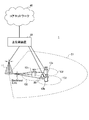
- FIG. 1 is an explanatory diagram of carrier aggregation (CA).
- CA carrier aggregation
- LTE Rel LTE Rel.
- CA carrier aggregation
- CC # 1 to CC # 5 component carriers
- CC component carriers
- UE User Equipment
- LTE Rel With 13 carrier aggregations, it is considered to bundle more than 6 CCs to further expand the bandwidth. That is, LTE Rel. In 13 carrier aggregation, it is considered to expand the number of CCs (cells) that can be set per user terminal to 6 or more (CA enhancement). For example, as shown in FIG. 1, when 32 CCs (CC # 1 to CC # 32) are bundled, a maximum band of 640 MHz can be secured.
- LAA License-Assisted Access
- the transmission method for example, format and transmission power
- LTE Rel. 10-12 the existing system
- the user terminal transmits uplink control information (UCI) using an uplink control channel (PUCCH: Physical plink Control Channel).
- UCI includes acknowledgment information (HARQ-ACK: Hybrid Automatic Repeat request-ACK) for downlink shared channel (PDSCH) of each CC and channel state information (CSI: Channel State) indicating the channel state.
- HARQ-ACK Hybrid Automatic Repeat request-ACK
- CSI Channel State
- SR Scheduling Request
- PUCCH formats 1 / 1a / 1b, 2 / 2a / 2b and 3 are supported as PUCCH formats (hereinafter referred to as PUCCH formats).
- PUCCH format 1 is used for transmission of SR.
- 1b / 3 based on PUCCH format 1a / 1b / channel selection is used for transmission of HARQ-ACK of 5 CC or less.
- PUCCH format 2 / 2a / 2b is used for transmission of CSI of a specific CC.
- the PUCCH format 2a / 2b may be used for transmission of HARQ-ACK in addition to CSI of a specific CC.
- PUCCH format 3 may be used for transmission of SR and / or CSI in addition to HARQ-ACK.
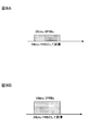
- FIG. 2 is a diagram illustrating a configuration example of PUCCH format 3 having a maximum payload among existing PUCCH formats.
- PUCCH format 3 UCI (for example, up to 5 CC HARQ-ACK) of up to 10 bits in FDD and up to 22 bits in TDD can be transmitted.
- PUCCH format 3 includes two demodulation reference signals (DMRS: DeModulation Reference Signal) and five SC-FDMA (Single Carrier Frequency Division Multiple Access) symbols per slot. The same bit string is mapped to each SC-FDMA symbol of each slot, and is multiplied by a spreading code (orthogonal code, also called OCC: Orthogonal Cover Code) in order to multiplex a plurality of user terminals.
- DMRS DeModulation Reference Signal
- SC-FDMA Single Carrier Frequency Division Multiple Access
- cyclic shifts also referred to as cyclic shifts or CSs
- CSs cyclic shifts
- orthogonal codes and cyclic shifts it is possible to code division multiplex (CDM) up to five PUCCH formats 3 on the same resource (PRB).
- CDM code division multiplex
- HARQ bit sequences can be orthogonally multiplexed using different spreading codes (OCC) for each user terminal
- DMRSs can be orthogonally multiplexed using different CS sequences for each user terminal.
- the PUCCH format 3 cannot transmit UCI for all scheduled CCs due to a lack of payload. Is assumed.
- a PUCCH format capable of transmitting 64 bits is required.
- PUCCH capable of transmitting 128 bits (when spatial bundling is applied) or 256 bits Formatting is required.
- a PUCCH (hereinafter referred to as a new PUCCH format) having a larger number of bits (payload, capacity) that can be transmitted than the existing PUCCH format so that UCI (for example, HARQ-ACK) of 6 CC or more can be transmitted. It is being considered.
- the transmission power of PUCCH is controlled based on the PUCCH format and the amount of information (payload) transmitted in the PUCCH format. Specifically, PUCCH transmission power P PUCCH (i) in subframe i is controlled based on Equation (1).
- P CMAX, c (i) is the maximum transmission power in subframe i of serving cell (also referred to as CC, cell, etc.) c.
- P 0_PUCCH is a parameter (offset) notified by an upper layer.
- PL c is a path loss of the user terminal in the serving cell c.
- h (n CQI , n HARQ , n SR ) (hereinafter also simply referred to as “h”) is a value (offset) depending on the PUCCH format.
- n CQI is the number of bits of CQI.
- n HARQ is the number of bits of HARQ-ACK.
- n SR is the number of bits of the SR field for making a scheduling request. It can be said that h is an offset based on the payload of the PUCCH format.
- h 0.
- h (n HARQ ⁇ 1) / 2.
- CP normal cyclic prefix
- h (n HARQ + n SR ⁇ 1) / 3.
- h (n HARQ + n SR ⁇ 1) / 2.
- h (n HARQ + n SR + n CQI ⁇ 1) / 3.
- h (n HARQ + n SR + n CQI ⁇ 1) / 2.
- ⁇ F_PUCCH (F) is a parameter (offset) based on the PUCCH format, and is notified by the higher layer.
- ⁇ TxD (F ′) is a parameter (offset) based on the presence / absence of transmission diversity (transmission at two antenna ports), and is notified by the upper layer.
- g (i) is a cumulative value of the TPC command.
- the present inventors have conceived of controlling the transmission power of the PUCCH in consideration of the configuration of the new PUCCH format when the number of CCs that can be set per user terminal is expanded to 6 or more.
- the CC may also be called a cell, a serving cell, or the like.
- the new PUCCH format is a transmission format in which the number of bits (payload, capacity) that can be transmitted is larger than that of the existing PUCCH format.
- the new PUCCH format may be called PUCCH format 4, large-capacity PUCCH format, extended PUCCH format, new format, or the like.
- the maximum number of bits that can be transmitted is 128 bits or more
- the number of transmission bits including HARQ-ACK and / or SR is a predetermined value (for example, 23 bits) or more.
- a cyclic redundancy check (CRC) is added to the HARQ-ACK transmission
- the number of transmission bits including HARQ-ACK and / or SR is greater than or equal to a predetermined value (for example, 23 bits).
- TBCC Transmission-Biting Convolutional Coding
- the number (type) of the new PUCCH format may be plural or one.
- the number of bits (payload) that can be transmitted such as the first new PUCCH format capable of transmitting 6CC HARQ-ACK and the second new PUCCH format capable of transmitting HARQ-ACK up to 32CC.
- a plurality of new PUCCH formats may be defined.
- a single new PUCCH format may be defined to prevent control complexity.
- the position and number of DMRSs arranged in the new PUCCH format may be the same as or different from those in PUCCH format 3. If the number of DMRSs arranged in the new PUCCH format is increased, channel estimation can be performed with high accuracy even in a low SINR environment or a high-speed moving environment. On the other hand, when the number of DMRSs is reduced, the payload (the number of bits that can be transmitted) can be increased, so that a higher coding gain can be easily obtained.
- FIG. 3 is a diagram showing a first configuration example (DMRS position and number) of the new PUCCH format.
- DMRSs may be arranged in the second and sixth SC-FDMA symbols (time symbols) of each slot, as in PUCCH format 3 (see FIG. 2).
- DMRS may be arranged in the fourth SC-FDM symbol of each slot.
- the position of the DMRS in the new PUCCH format is not limited to the positions shown in FIGS. 3A and 3B, and may be any SC-FDMA symbol in each slot.
- the number of DMRSs in the new PUCCH format is not limited to the number shown in FIGS. 3A and 3B (2 or 1 per slot), and may be 3 or more per slot.
- the number of frequency resources (also referred to as physical resource blocks (PRB), resource blocks, etc., hereinafter referred to as PRB) used in the new PUCCH format may be the same as PUCCH format 3 or larger than PUCCH format 3. May be. If the number of PRBs used in the new PUCCH format is increased, the payload per PRB is reduced, so that the coding gain can be increased while the overhead is increased.
- PRB physical resource blocks
- FIG. 4 is a diagram showing a second configuration example (number of PRBs) of the new PUCCH format.
- the new PUCCH format as in PUCCH format 3 (see FIG. 2), 1 PRB per slot may be used, and frequency hopping may be applied between slots.
- a plurality of PRBs (3 PRBs in FIG. 4) may be used per slot, and frequency hopping may be applied between the slots.
- the number of PRBs used in the new PUCCH format is not limited to the numbers shown in FIGS. 4A and 4B, and may be 2 PRBs per slot or 4 PRBs or more. 4A and 4B, frequency hopping is applied between slots, but the frequency hopping may not be applied. Further, the position and number of DMRSs are not limited to those shown in FIGS. 4A and 4B.
- a plurality of user terminals may be code division multiplexed (CDM), frequency division multiplexed (FDM), and / or time division multiplexed (TDM).
- CDM code division multiplexed
- FDM frequency division multiplexed
- TDM time division multiplexed
- a plurality of user terminals can be accommodated in the same PRB, but the payload per user terminal becomes small and it is difficult to obtain a coding gain.
- FIG. 5 is a diagram illustrating a third configuration example of the new PUCCH format (a method for multiplexing a plurality of user terminals).
- a plurality of user terminals may be code division multiplexed.
- UCIs of a plurality of user terminals are orthogonally multiplexed using different spreading codes (OCC) for each user terminal, and different cyclic shifts are applied to each user terminal.
- OCC spreading codes
- DMRS of a plurality of user terminals may be orthogonally multiplexed.
- a plurality of user terminals may be frequency division multiplexed. Specifically, UCI and DMRS of a plurality of user terminals may be mapped to different PRBs.
- the multiplexing method of a plurality of user terminals in the new PUCCH format is not limited to the multiplexing method shown in FIGS. 4A and 4B.
- a plurality of user terminals may be time division multiplexed, or time division multiplexed and frequency division multiplexed.
- a plurality of user terminals may be space-division multiplexed.
- the spreading factor (orthogonal code length) used in the new PUCCH format may be the same as that of PUCCH format 3 or may be reduced as compared with PUCCH format 3.
- the spreading factor used in the new PUCCH format is reduced, the payload (number of bits that can be transmitted) per user terminal increases, while the number of user terminals that can be multiplexed decreases.
- FIG. 6 is a diagram showing a fourth configuration example (spreading factor) of the new PUCCH format.
- the new PUCCH format as in PUCCH format 3, the same bit string is mapped to each SC-FDMA symbol excluding DMRS, and each user terminal is multiplexed to multiplex a plurality of user terminals. Different spreading codes may be multiplied.
- a different bit string may be mapped to each SC-FDMA symbol excluding DMRS by setting the spreading factor to 1, for example.
- the bit sequence length that can be transmitted is five times that of FIG. 6A, but the number of user terminals that can be multiplexed is limited to one.
- the modulation method used in the new PUCCH format may be BPSK (Binary Phase Shift Keying) or QPSK (Quadrature Phase Shift Keying) used in the existing PUCCH format, or a multi-value of 16 QAM (Quadrature Amplitude Modulation) or more.
- a modulation method may be used.
- a reference signal other than DMRS for example, SRS: Sounding Reference Signal
- SRS Sounding Reference Signal
- the user terminal in which uplink carrier aggregation is set may be set to the conventional PUCCH format or the new PUCCH format in each of two or more CCs.
- two or more cell groups (CG) including each CC in which the PUCCH format is set are set in the user terminal, and HARQ-ACK feedback control is performed in each PUCCH format for each CG.
- the user terminal performs the multiplication of the number of PRBs (number of resource blocks) constituting the PUCCH format, the compensation coefficient set smaller than 1 and the path loss, and the CRC in the PUCCH format.
- the transmission power of PUCCH is controlled based on at least one of a payload including bits and a payload not including CRC bits in the PUCCH format.
- transmission power control based on the number of PRBs (first mode), transmission power control based on the multiplication result of a compensation coefficient set smaller than 1 and a path loss (second mode), based on the presence or absence of CRC bits
- first mode transmission power control based on the number of PRBs
- second mode transmission power control based on the multiplication result of a compensation coefficient set smaller than 1
- second mode transmission power control based on the presence or absence of CRC bits
- the transmission power control (third aspect) will be described in detail. Note that the transmission power control according to the first to third aspects may be used alone, or may be used in combination of at least two.
- the transmission power control according to the present embodiment is not limited to the first to third aspects.
- the transmission power of the PUCCH includes the configuration of the above-described new PUCCH format (for example, the location and number of DMRS (FIG. 3), the number of PRBs (FIG. 4), and a multiplexing scheme of a plurality of user terminals (FIG. 5).
- Various control may be performed based on the presence / absence of CRC bits, the position and number of SRS, the spreading factor (FIG. 6), the modulation scheme, the mapping order of information bit sequences to radio resources, and the like.
- formulas (2) to (5) described later are merely examples, and parameters may be added / deleted / changed.
- the calculation of the power headroom is also performed on the assumption of the corresponding transmission power control. That is, when the user terminal applies transmission power control according to the present embodiment, the maximum power in subframe i of serving cell (also referred to as CC, cell, etc.) c is used for calculation of power headroom to be reported to the radio base station. A value obtained by subtracting the transmission power calculated based on the transmission power control according to the present embodiment from the transmission power P CMAX, c (i) can be reported as a power headroom to the radio base station.
- Power Headroom is surplus transmission power of the user terminal.
- the surplus transmission power may be calculated based on the maximum transmission power and the PUSCH transmission power (for example, by subtracting the PUSCH transmission power from the maximum transmission power) (type 1), or the maximum transmission power and PUSCH.
- the transmission power of PUCCH for example, by subtracting the transmission power of PUSCH and PUCCH from the maximum transmission power
- the surplus transmission power of the user terminal can be calculated using the transmission power of PUCCH controlled by the transmission power control according to the present embodiment.
- the user terminal may control the transmission power of the PUCCH based on the number of PRBs so that the transmission power per PRB is constant.
- the user terminal may control the transmission power of the PUCCH based on an offset that increases (may be proportional) according to the number of PRBs.
- the user terminal may control the transmission power of the PUCCH based on the payload per PRB calculated based on the number of PRBs.
- the user terminal controls the transmission power P PUCCH (i) of PUCCH in subframe i based on Equation (2).
- M PUCCH, c (i) is the number of PRBs constituting the PUCCH format in subframe i.
- M PUCCH, c (i) is 1, and in the new PUCCH format, M PUCCH, c (i) is 1 or more.
- h (n CQI , n HARQ , n SR ) / M PUCCH, c (i) is considered as a transmission power offset (parameter) depending on the payload per PRB.
- the transmission power (transmission energy) in the case of 20 bits per 1 PRB (FIG. 8B) is controlled to be larger than that in the case of 10 bits per 1 PRB (FIG. 8A). Is done.
- control is performed such that the transmission power is increased when the number of PRBs is small.
- the required received SINR that satisfies a predetermined error rate depends on the payload per received PRB number (or bandwidth).
- the transmission power of the PUCCH is controlled using an offset (for example, (h (n CQI , n HARQ , n SR ) / M PUCCH, c (i)) that increases with an increase in the payload per number of PRBs.
- the user terminal may control the PUCCH transmission power P PUCCH (i) in subframe i based on Equation (3).
- n CQI is the number of bits of CQI.
- n HARQ is the number of bits of HARQ-ACK.
- n SR is the number of bits of the SR field (hereinafter abbreviated as SR) for making a scheduling request, and is generally composed of 1 bit (in the case of PUCCH format 3, the user terminal determines whether there is an uplink scheduling request) In response, the SR bit is transmitted as 1 or 0).
- M PUCCH, c (i) is the same as the above formula (2), and P CMAX, c (i), P 0_PUCCH , PL c , ⁇ F_PUCCH (F), ⁇ TxD (F ′), g ( Since i) is the same as the above formula (1), description thereof is omitted.
- the number of CQI bits per PRB (for example, n CQI / M PUCCH, c (i)), HARQ-ACK per PRB is used as an offset that increases with an increase in payload per PRB.
- the function h based on the number of bits (for example, n HARQ / M PUCCH, c (i)) and the SR per PRB (for example, n SR / M PUCCH, c (i)) is used.
- the offset h can be more appropriately expressed as a function of the payload per PRB, so the payload per PRB Therefore, it is possible to more appropriately set a transmission power offset that conforms to the required SINR corresponding to the.
- the transmission power offset is expressed as h (n CQI , n HARQ , n SR , MPUCC, c (i)), and as a function of the PRB number of CQI, HARQ, SR payload and PUCCH, as a more general notation Also good.
- the user terminal can determine the number of PRBs constituting the PUCCH format based on notification information by higher layer signaling and / or downlink control information (DCI) transmitted by the downlink control channel (PDCCH or EPDCCH). May be determined.
- DCI downlink control information
- the notification information (control information) by the higher layer signaling includes, for example, the number of CCs set in the user terminal, the maximum number of MIMO (Multiple Input and Multiple Output) layers per CC (transmission mode (TM)), At least one UL-DL configuration (configuration of uplink subframe and downlink subframe in TDD) per CC may be included.
- MIMO Multiple Input and Multiple Output
- TDD transmission mode
- the DCI includes the total number of CCs scheduled in the user terminal (TDAI: Total Downlink Assignment Indicator), the cumulative number of scheduled CCs (ADAI: Accumulated Downlink Assignment Indicator), the user terminal. May include at least one of bitmaps indicating CCs to be scheduled among the CCs set in. Note that these pieces of information may be included in DCI for scheduling PDSCH.
- the user terminal determines a payload based on notification information by higher layer signaling or / and the DCI, and determines the number of PRBs constituting the new PUCCH format based on the determined payload. May be.
- the number of PRBs constituting the PUCCH format may be notified directly to the user terminal by higher layer signaling.
- the PRB number is quasi-statically fixed regardless of the dynamically changed payload.
- the new PUCCH format is configured with a plurality of PRBs.
- a performance improvement effect can be expected.
- ⁇ Second aspect> In the second mode, transmission power control based on a multiplication result of a compensation coefficient set smaller than 1 and a path loss will be described.
- the new PUCCH format is configured to perform frequency division multiplexing and / or time division multiplexing of a plurality of user terminals (see FIG. 5B), as in the case of code division multiplexing of a plurality of user terminals (see FIG. 5A), Intersymbol interference (in-cell perspective problem) due to the difference in reception quality at the radio base station between user terminals does not occur.
- the compensation coefficient (hereinafter referred to as path loss compensation coefficient) ⁇ multiplied by the path loss PL c is fixed to 1, and the reception quality (target received power) at the radio base station is made constant. There is no need to make it.
- the transmission power of PUCCH is controlled based on the multiplication result.
- the path loss compensation coefficient ⁇ when the path loss compensation coefficient ⁇ is fixed to 1, the reception quality (target received power) at the radio base station is constant regardless of the magnitude of the path loss (that is, the distance from the cell center). .
- the path loss compensation coefficient ⁇ when the path loss compensation coefficient ⁇ is set to be smaller than 1, a user terminal with a smaller path loss (closer to the cell center) has a higher transmission power and better reception quality at the radio base station.
- the transmission power can be increased as the path loss is smaller. Since the user terminal with a smaller path loss (closer to the center of the cell) is more likely to perform downlink scheduling, the above control can improve the throughput of user terminals with good reception quality and improve best effort. be able to.
- the user terminal may control the transmission power P PUCCH (i) of PUCCH in subframe i based on equation (4).
- ⁇ is a path loss compensation coefficient, and 0 ⁇ ⁇ ⁇ 1.
- ⁇ 1 in the existing PUCCH format and ⁇ ⁇ 1 in the new PUCCH format.
- P CMAX, c (i) P 0 — PUCCH , PL c , h (n CQI , n HARQ , n SR ), ⁇ F — PUCCH (F), ⁇ TxD (F ′), g (i) Since this is the same as 1), the description is omitted.
- the value of the path loss compensation coefficient ⁇ smaller than 1 may be notified to the user terminal by higher layer signaling.
- the value of the path loss compensation coefficient ⁇ of each new PUCCH format may be notified to the user terminal by higher layer signaling. In this case, the value of the path loss compensation coefficient ⁇ may be different for each new PUCCH format.
- a plurality of path loss compensation coefficient ⁇ values that differ depending on the payload (size of information bit sequence) included in one new PUCCH format may be notified to the user terminal by higher layer signaling.
- the transmission power of the PUCCH using the PUCCH format is controlled based on the multiplication result of the path loss compensation coefficient ⁇ and the path loss set to be smaller than 1, so that the path loss becomes smaller.
- the transmission power increases. As a result, the throughput of the user terminal with good reception quality can be improved, and the best effort can be enhanced.
- an error in the information bit can be easily detected in the radio base station by adding a CRC bit to the information bit.
- a radio base station detects a CRC error in the CQI, it can prevent scheduling based on erroneous CQI information by regarding this as invalid information.
- a radio base station detects a CRC error in HARQ-ACK, it can avoid missing a retransmission request from the terminal by regarding all the HARQ-ACK bits included as NACK.
- the number of information bits to which CRC bits are added is not limited to 23 or more bits. That is, the predetermined number may be any of 1-22, or may be 24 or more.
- the error detection by the CRC bit can prevent the radio base station from erroneously detecting the NACK transmitted from the user terminal as an ACK (NACK-to-ACK error), and thus the probability that the retransmission request from the user terminal is missed.
- NACK-to-ACK error the probability that the retransmission request from the user terminal is missed. The effect of improving throughput can be expected.
- a user terminal controls the transmission power of PUCCH based on the payload containing a CRC bit, or based on the payload which does not contain a CRC bit.
- the user terminal transmits PUCCH transmission power based on a payload including the information bits and the CRC bits. May be controlled. Since it is possible to set appropriate transmission power according to the actual payload by using the payload including the CRC bits, it is easy to achieve the required SINR in the radio base station.
- the user terminal may control the transmission power P PUCCH (i) of PUCCH in subframe i based on equation (5).
- h (n CQI , n HARQ , n SR , n CRC ) is an offset based on the payload including the CRC bits.
- n CQI is the number of bits of CQI.
- n HARQ is the number of bits of HARQ-ACK.
- n SR is the number of bits in the SR field for making a scheduling request, and is generally composed of 1 bit (in the case of PUCCH format 3, the terminal sets the SR bit according to the presence or absence of an uplink scheduling request to 1 or Send as 0).
- the n CRC is the number of CRC bits added to information bits including at least one of HARQ-ACK, CQI, and SR.
- the number of CRC bits may be a fixed value such as 8 bits or 16 bits, for example.
- h (n CQI , n HARQ , n SR , n CRC ) may consider the weight of CRC bits for information bits (at least one of CQI, HARQ-ACK, SR). .
- the value of h (n CQI , n HARQ , n SR , n CRC ) may be defined similarly to h (n CQI , n HARQ , n SR ) in Expression (1).
- P CMAX, c (i), P 0_PUCCH , PL c , ⁇ F_PUCCH (F), ⁇ TxD (F ′), and g (i) are the same as the above formula (1), and thus the description thereof is omitted. .
- the user terminal may control the transmission power of PUCCH based on a payload that does not include CRC bits. Based on a payload that does not include a CRC bit, it is possible to set an appropriate transmission power according to an increase or decrease in information bits without being affected by the CRC bit.
- the user terminal can transmit the PUCCH transmission power P PUCCH in subframe i based on the above equation (1).
- (I) may be controlled.
- FIG. 10 is a diagram showing the relationship between payload and transmission power when a fixed-length CRC bit is added to 22 or more HARQ-ACK bits in the new PUCCH format.
- A when an offset based on a payload including a CRC is used (A), transmission power for a fixed-length CRC bit is added with 22 bits as a boundary.
- B when an offset based on a payload that does not include a CRC is used (B), transmission power increases according to the number of HARQ-ACK bits.
- the PUCCH format is A transmission power suitable for a case where a CRC bit is added to a predetermined number of information bits or more can be set.
- wireless communication system Wireless communication system
- the radio communication method according to each aspect of the present invention is applied.
- wireless communication method which concerns on each said aspect may be applied independently, respectively, and may be applied in combination.
- FIG. 11 is a diagram illustrating an example of a schematic configuration of a wireless communication system according to an embodiment of the present invention.
- carrier aggregation (CA) and / or dual connectivity (DC) in which a plurality of basic frequency blocks (component carriers) each having a system bandwidth (for example, 20 MHz) of the LTE system as one unit are applied.
- the wireless communication system 1 may be referred to as SUPER 3G, LTE-A (LTE-Advanced), IMT-Advanced, 4G, 5G, FRA (Future Radio Access), or the like.
- a radio communication system 1 shown in FIG. 11 includes a radio base station 11 that forms a macro cell C1, and radio base stations 12a to 12c that are arranged in the macro cell C1 and form a small cell C2 narrower than the macro cell C1. . Moreover, the user terminal 20 is arrange
- the user terminal 20 can be connected to both the radio base station 11 and the radio base station 12. It is assumed that the user terminal 20 uses the macro cell C1 and the small cell C2 that use different frequencies simultaneously by CA or DC. In addition, the user terminal 20 can apply CA or DC using a plurality of cells (CC) (for example, six or more CCs).
- CC cells
- Communication between the user terminal 20 and the radio base station 11 can be performed using a carrier having a relatively low frequency band (for example, 2 GHz) and a narrow bandwidth (referred to as an existing carrier or a legacy carrier).
- a carrier having a relatively high frequency band for example, 3.5 GHz, 5 GHz, etc.
- the same carrier may be used.
- the configuration of the frequency band used by each radio base station is not limited to this.
- a wired connection for example, an optical fiber compliant with CPRI (Common Public Radio Interface), an X2 interface, etc.
- a wireless connection It can be set as the structure to do.
- the radio base station 11 and each radio base station 12 are connected to the higher station apparatus 30 and connected to the core network 40 via the higher station apparatus 30.
- the upper station device 30 includes, for example, an access gateway device, a radio network controller (RNC), a mobility management entity (MME), and the like, but is not limited thereto.
- RNC radio network controller
- MME mobility management entity
- Each radio base station 12 may be connected to the higher station apparatus 30 via the radio base station 11.
- the radio base station 11 is a radio base station having a relatively wide coverage, and may be called a macro base station, an aggregation node, an eNB (eNodeB), a transmission / reception point, or the like.
- the radio base station 12 is a radio base station having local coverage, and includes a small base station, a micro base station, a pico base station, a femto base station, a HeNB (Home eNodeB), an RRH (Remote Radio Head), and transmission / reception. It may be called a point.
- the radio base stations 11 and 12 are not distinguished, they are collectively referred to as a radio base station 10.
- Each user terminal 20 is a terminal compatible with various communication methods such as LTE and LTE-A, and may include not only a mobile communication terminal but also a fixed communication terminal.
- OFDMA orthogonal frequency division multiple access
- SC-FDMA single carrier-frequency division multiple access
- OFDMA is a multi-carrier transmission scheme that performs communication by dividing a frequency band into a plurality of narrow frequency bands (subcarriers) and mapping data to each subcarrier.
- SC-FDMA is a single-carrier transmission scheme that reduces interference between terminals by dividing the system bandwidth into bands consisting of one or continuous resource blocks for each terminal and using a plurality of terminals with mutually different bands. is there.
- the uplink and downlink radio access methods are not limited to these combinations.
- downlink channels include a downlink shared channel (PDSCH) shared by each user terminal 20, a broadcast channel (PBCH: Physical Broadcast Channel), a downlink L1 / L2 control channel, and the like. Used. User data, higher layer control information, SIB (System Information Block), etc. are transmitted by PDSCH. Also, MIB (Master Information Block) is transmitted by PBCH.
- PDSCH downlink shared channel
- PBCH Physical Broadcast Channel
- SIB System Information Block
- MIB Master Information Block
- Downlink L1 / L2 control channels include downlink control channels (PDCCH (Physical Downlink Control Channel), EPDCCH (Enhanced Physical Downlink Control Channel)), PCFICH (Physical Control Format Indicator Channel), PHICH (Physical Hybrid-ARQ Indicator Channel), etc. Including. Downlink control information (DCI: Downlink Control Information) including scheduling information of PDSCH and PUSCH is transmitted by PDCCH. The number of OFDM symbols used for PDCCH is transmitted by PCFICH. The HAICH transmission confirmation information (ACK / NACK) for PUSCH is transmitted by PHICH.
- EPDCCH is frequency-division multiplexed with PDSCH (downlink shared data channel), and is used for transmission of DCI and the like in the same manner as PDCCH.
- an uplink shared channel (PUSCH: Physical Uplink Shared Channel), an uplink control channel (PUCCH: Physical Uplink Control Channel), and a random access channel (PRACH) shared by each user terminal 20 are used. Physical Random Access Channel) is used.
- PUSCH Physical Uplink Shared Channel
- PUCCH Physical Uplink Control Channel
- PRACH random access channel
- User data and higher layer control information are transmitted by the PUSCH.
- Uplink control information including at least one of delivery confirmation information (ACK / NACK) and radio quality information (CQI) is transmitted by PUSCH or PUCCH.
- a random access preamble for establishing connection with a cell is transmitted by the PRACH.
- FIG. 12 is a diagram illustrating an example of the overall configuration of a radio base station according to an embodiment of the present invention.
- the radio base station 10 includes a plurality of transmission / reception antennas 101, an amplifier unit 102, a transmission / reception unit 103, a baseband signal processing unit 104, a call processing unit 105, and a transmission path interface 106.
- each of the transmission / reception antenna 101, the amplifier unit 102, and the transmission / reception unit 103 may be configured to include one or more.
- User data transmitted from the radio base station 10 to the user terminal 20 via the downlink is input from the higher station apparatus 30 to the baseband signal processing unit 104 via the transmission path interface 106.
- PDCP Packet Data Convergence Protocol
- RLC Radio Link Control
- MAC Medium Access Control
- HARQ Hybrid Automatic Repeat reQuest
- the downlink control signal is also subjected to transmission processing such as channel coding and inverse fast Fourier transform, and is transferred to the transmission / reception unit 103.
- the transmission / reception unit 103 converts the baseband signal output by precoding for each antenna from the baseband signal processing unit 104 to a radio frequency band and transmits the converted signal.
- the radio frequency signal frequency-converted by the transmission / reception unit 103 is amplified by the amplifier unit 102 and transmitted from the transmission / reception antenna 101.
- the transmitter / receiver, the transmission / reception circuit, or the transmission / reception device can be configured based on common recognition in the technical field according to the present invention.
- the transmission / reception part 103 may be comprised as an integral transmission / reception part, and may be comprised from a transmission part and a receiving part.
- the radio frequency signal received by the transmission / reception antenna 101 is amplified by the amplifier unit 102.
- the transmission / reception unit 103 receives the uplink signal amplified by the amplifier unit 102.
- the transmission / reception unit 103 converts the frequency of the received signal into a baseband signal and outputs it to the baseband signal processing unit 104.
- the baseband signal processing unit 104 performs fast Fourier transform (FFT) processing, inverse discrete Fourier transform (IDFT: Inverse Discrete Fourier Transform) processing, and error correction on user data included in the input upstream signal.
- FFT fast Fourier transform
- IDFT inverse discrete Fourier transform
- Decoding, MAC retransmission control reception processing, RLC layer and PDCP layer reception processing are performed and transferred to the upper station apparatus 30 via the transmission path interface 106.
- the call processing unit 105 performs call processing such as communication channel setting and release, state management of the radio base station 10, and radio resource management.
- the transmission path interface 106 transmits and receives signals to and from the higher station apparatus 30 via a predetermined interface.
- the transmission path interface 106 transmits and receives (backhaul signaling) signals to and from the adjacent radio base station 10 via an interface between base stations (for example, an optical fiber compliant with CPRI (Common Public Radio Interface), X2 interface). Also good.
- CPRI Common Public Radio Interface
- X2 interface also good.
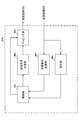
- FIG. 13 is a diagram illustrating an example of a functional configuration of the radio base station according to the present embodiment.
- FIG. 13 mainly shows functional blocks of characteristic portions in the present embodiment, and the radio base station 10 also has other functional blocks necessary for radio communication.
- the baseband signal processing unit 104 includes a control unit 301, a transmission signal generation unit 302, a mapping unit 303, and a reception signal processing unit 304.
- the control unit 301 controls the entire radio base station 10.
- the control unit 301 controls, for example, downlink signal generation by the transmission signal generation unit 302, signal mapping by the mapping unit 303, and signal reception processing by the reception signal processing unit 304.
- control unit 301 controls transmission of downlink user data (for example, modulation scheme, coding rate, resource allocation (scheduling), etc.) based on channel state information (CSI) reported from the user terminal 20. Control).
- downlink user data for example, modulation scheme, coding rate, resource allocation (scheduling), etc.
- CSI channel state information
- control unit 301 controls mapping of downlink control information (DCI) including resource allocation information (DL / UL grant) for downlink / uplink user data to the downlink control channel (PDCCH and / or EPDCCH). Further, the control unit 301 controls mapping of downlink reference signals such as CRS (Cell-specific Reference Signal) and CSI-RS (Channel State Information Reference Signal).
- DCI downlink control information
- DL / UL grant resource allocation information
- DL / UL grant resource allocation information
- CSI-RS Channel State Information Reference Signal
- control unit 301 controls carrier aggregation (CA) of the user terminal 20. Specifically, the control unit 301 determines CA application / change in the number of CCs based on CSI reported from the user terminal 20 and the like, and generates a transmission signal so as to generate information indicating the application / change.
- the unit 302 may be controlled. Note that the information indicating the application / change may be included in control information that is signaled by higher layers.
- control unit 301 may control the maximum number of MIMO per CC (transmission mode (TM)) and the UL / DL configuration per CC in TDD.
- the maximum MIMO number and UL / DL configuration may be included in control information (notification information) notified to the user terminal 20 by higher layer signaling.
- control unit 301 includes the total number of CCs scheduled for the CCs set for the user terminal 20 (TDAI), the cumulative number of CCs to be scheduled (ADAI), and the CCs set for the user terminal 20. At least one of bitmaps indicating CCs to be scheduled may be determined. Note that these pieces of information may be included in DCI for scheduling PDSCH.
- control unit 301 controls parameters used for PUCCH transmission power control (closed loop control, open loop control). Specifically, the control unit 301 determines an increase / decrease value of the transmission power control (TPC) command based on the reception quality of the uplink signal from the user terminal 20.
- the TPC command may be included in DCI transmitted to the user terminal 20 by PDCCH.
- the control unit 301 also includes a parameter based on target received power in the radio base station (for example, P 0_PUCCH ), a parameter based on the PUCCH format (for example, ⁇ F_PUCCH (F)), and a parameter based on the presence / absence of transmission diversity (for example, , ⁇ TxD (F ′)) is determined.
- P 0_PUCCH target received power in the radio base station
- F ⁇ F_PUCCH
- F a parameter based on the presence / absence of transmission diversity for example, ⁇ TxD (F ′)
- control unit 301 may determine the number of PRBs constituting the PUCCH format (first mode). The number of PRBs may be included in control information (notification information) notified to the user terminal 20 by higher layer signaling.
- control unit 301 may determine the path loss guarantee coefficient ⁇ (second mode).
- the path loss guarantee coefficient ⁇ may be included in control information (notification information) notified to the user terminal 20 by higher layer signaling.
- the control unit 301 may change whether or not the path loss guarantee coefficient ⁇ is set to be smaller than 1 according to the PUCCH format.
- the control unit 301 may determine the path loss guarantee coefficient ⁇ to be smaller than 1 in the case of the new PUCCH format, and may determine the path loss guarantee coefficient ⁇ to be 1 in the case of the existing PUCCH format.
- control unit 301 may determine the path loss guarantee coefficient ⁇ to be smaller than 1 when the new PUCCH format is configured to frequency multiplex or / and time multiplex multiple user terminals 20. In addition, when a plurality of new PUCCH formats are set, the control unit 301 may determine a different path loss guarantee coefficient ⁇ for each new PUCCH format. In addition, when a single new PUCCH format is composed of a plurality of different payloads, the control unit 301 may determine a different path loss guarantee coefficient ⁇ depending on the payload of the new PUCCH format.
- the control unit 301 can be configured by a controller, a control circuit, or a control device described based on common recognition in the technical field according to the present invention.
- the transmission signal generation unit 302 generates a downlink signal (including a downlink data signal and a downlink control signal) based on an instruction from the control unit 301 and outputs it to the mapping unit 303. Specifically, the transmission signal generation unit 302 generates a downlink data signal (PDSCH) including notification information (control information) by the above-described higher layer signaling and user data, and outputs it to the mapping unit 303. Also, the transmission signal generation unit 302 generates a downlink control signal (PDCCH) including the above-described DCI, and outputs the downlink control signal (PDCCH) to the mapping unit 303. Also, the transmission signal generation unit 302 generates downlink reference signals such as CRS and CSI-RS, and outputs them to the mapping unit 303.
- PDSCH downlink data signal
- PDCCH downlink control signal
- the transmission signal generation unit 302 generates downlink reference signals such as CRS and CSI-RS, and outputs them to the mapping unit 303.
- the transmission signal generation unit 302 can be a signal generator, a signal generation circuit, or a signal generation device described based on common recognition in the technical field according to the present invention.
- the mapping unit 303 maps the downlink signal generated by the transmission signal generation unit 302 to a predetermined radio resource based on an instruction from the control unit 301, and outputs it to the transmission / reception unit 103.
- the mapping unit 303 can be a mapper, a mapping circuit, or a mapping device described based on common recognition in the technical field according to the present invention.
- the reception signal processing unit 304 performs reception processing (for example, demapping, demodulation, decoding, etc.) on the uplink signal transmitted from the user terminal 20.
- the processing result is output to the control unit 301.
- the reception signal processing unit 304 detects the PUCCH format and performs reception processing of UCI (at least one of HARQ-ACK, CQI, and SR).
- the reception signal processing unit 304 may be composed of a signal processor, a signal processing circuit or a signal processing device, and a measuring device, a measurement circuit or a measuring device which are described based on common recognition in the technical field according to the present invention. it can.
- FIG. 14 is a diagram illustrating an example of an overall configuration of a user terminal according to an embodiment of the present invention.
- the user terminal 20 includes a plurality of transmission / reception antennas 201 for MIMO transmission, an amplifier unit 202, a transmission / reception unit 203, a baseband signal processing unit 204, and an application unit 205.
- the radio frequency signals received by the plurality of transmission / reception antennas 201 are each amplified by the amplifier unit 202.
- Each transmitting / receiving unit 203 receives the downlink signal amplified by the amplifier unit 202.
- the transmission / reception unit 203 converts the frequency of the received signal into a baseband signal and outputs it to the baseband signal processing unit 204.
- the baseband signal processing unit 204 performs FFT processing, error correction decoding, retransmission control reception processing, and the like on the input baseband signal.
- the downlink user data is transferred to the application unit 205.
- the application unit 205 performs processing related to layers higher than the physical layer and the MAC layer.
- broadcast information in the downlink data is also transferred to the application unit 205.
- uplink user data is input from the application unit 205 to the baseband signal processing unit 204.
- the baseband signal processing unit 204 performs retransmission control transmission processing (for example, HARQ transmission processing), channel coding, precoding, discrete Fourier transform (DFT) processing, IFFT processing, and the like.
- the data is transferred to the transmission / reception unit 203.
- the transmission / reception unit 203 converts the baseband signal output from the baseband signal processing unit 204 into a radio frequency band and transmits it.
- the radio frequency signal frequency-converted by the transmission / reception unit 203 is amplified by the amplifier unit 202 and transmitted from the transmission / reception antenna 201.
- the transmission / reception unit 203 can be a transmitter / receiver, a transmission / reception circuit, or a transmission / reception device described based on common recognition in the technical field according to the present invention. Further, the transmission / reception unit 203 may be configured as an integral transmission / reception unit, or may be configured from a transmission unit and a reception unit.
- FIG. 15 is a diagram illustrating an example of a functional configuration of the user terminal according to the present embodiment. Note that FIG. 15 mainly shows functional blocks of characteristic portions in the present embodiment, and the user terminal 20 also has other functional blocks necessary for wireless communication. As illustrated in FIG. 15, the baseband signal processing unit 204 included in the user terminal 20 includes a control unit 401, a transmission signal generation unit 402, a mapping unit 403, a reception signal processing unit 404, and a measurement unit 405. I have.
- the control unit 401 controls the entire user terminal 20.
- the control unit 401 controls, for example, signal generation by the transmission signal generation unit 402, signal mapping by the mapping unit 403, and signal reception processing by the reception signal processing unit 404.
- the control unit 401 controls the PUCCH format applied to the transmission of UCI (at least one of HARQ-ACK, CQI, and SR). Specifically, the control unit 401 determines whether to apply a new PUCCH format or an existing PUCCH format according to the number of CCs set for the user terminal 20 or the number of CCs scheduled for the user terminal 20. Also good. Further, when a plurality of new PUCCH formats are provided, the control unit 401 may determine a new PUCCH format to be applied according to the UCI payload.
- control unit 401 determines the number of PRBs constituting the PUCCH format (first mode), the multiplication result (second mode) of the path loss compensation coefficient ⁇ and path loss set to be smaller than 1, and the PUCCH format.
- the transmission power of the PUCCH is controlled based on at least one of the payload including the CRC bits (third aspect) and the payload not including the CRC bits in the PUCCH format (third aspect).
- the control unit 401 controls the transmission power of the PUCCH based on the number of PRBs so that the transmission power per PRB is constant. Also good.
- the control unit 401 may control the transmission power of the PUCCH based on the payload per PRB calculated based on the number of PRBs. For example, the control unit 401 may control the transmission power of the PUCCH using the above formula (2) or the formula (3).
- the number of PRBs constituting the PUCCH may be notified to the user terminal 20 by higher layer signaling.
- the control unit 401 may notify information by higher layer signaling (for example, the number of CCs set in the user terminal 20, the maximum number of MIMO layers per CC (TM), the UL / DL configuration per CC) or / and DCI (
- the number of PRBs constituting the PUCCH format may be determined based on the TDAI, ADIA, and bitmap).
- the control unit 401 may determine a payload based on the control information and / or DCI that is signaled by the higher layer, and may determine the number of PRBs based on the payload.
- the path loss compensation coefficient (compensation coefficient) set to be smaller than 1
- the transmission power of PUCCH is controlled.
- the control unit 401 may control the transmission power of the PUCCH using the above equation (4).
- the path loss guarantee coefficient ⁇ may be notified to the user terminal 20 by higher layer signaling.
- the control unit 401 determines the PUCCH based on the payload including the information bits and the CRC bits.
- the transmission power may be controlled.
- the control unit 401 may control the transmission power of the PUCCH using the above equation (5).
- the offset based on the payload may be set in consideration of the weight of the CRC bits with respect to the information bits.
- the user terminal controls the transmission power of the PUCCH based on a payload not including the CRC bits. May be.
- the control unit 401 may control the transmission power of the PUCCH using the above equation (1).
- control unit 401 also includes a configuration of a new PUCCH format (for example, the location and number of DMRS (FIG. 3), the number of PRBs (FIG. 4), a multiplexing scheme of a plurality of user terminals (FIG. 5), CRC
- the transmission power may be controlled variously based on the presence / absence of bits, the position and number of SRS, the spreading factor (FIG. 6), the modulation scheme, the order of mapping information bit sequences to radio resources, and the like.
- the control part 401 may calculate surplus transmission power (PH: Power Headroom) based on the transmission power and maximum transmission power of PUCCH controlled as mentioned above. The calculated surplus transmission power may be transmitted to the radio base station 10 (PHR: Power Headroom Report).
- PHR Power Headroom Report
- the control unit 401 can be configured by a controller, a control circuit, or a control device described based on common recognition in the technical field according to the present invention.
- the transmission signal generation unit 402 generates an uplink signal (including an uplink data signal and an uplink control signal) based on an instruction from the control unit 401 and outputs the uplink signal to the mapping unit 403. For example, the transmission signal generation unit 402 generates an uplink control signal (PUCCH) including UCI (at least one of HARQ-ACK, CQI, and SR).
- PUCCH uplink control signal
- the transmission signal generation unit 402 can be a signal generator, a signal generation circuit, or a signal generation device described based on common recognition in the technical field according to the present invention.
- the mapping unit 403 Based on an instruction from the control unit 401, the mapping unit 403 maps the uplink signal (uplink control signal and / or uplink data signal) generated by the transmission signal generation unit 402 to a radio resource and outputs the radio resource to the transmission / reception unit 203. To do.
- the mapping unit 403 may be a mapper, a mapping circuit, or a mapping device described based on common recognition in the technical field according to the present invention.
- the reception signal processing unit 404 performs reception processing (for example, demapping, demodulation, decoding, etc.) on downlink signals (including downlink control signals and downlink data signals).
- the reception signal processing unit 404 outputs information received from the radio base station 10 to the control unit 401.
- the received signal processing unit 404 outputs, for example, broadcast information, system information, control information by higher layer signaling such as RRC signaling, DCI, and the like to the control unit 401.
- the received signal processing unit 404 can be configured by a signal processor, a signal processing circuit, or a signal processing device described based on common recognition in the technical field according to the present invention. Further, the reception signal processing unit 404 can constitute a reception unit according to the present invention.
- the measurement unit 405 measures the channel state based on a reference signal (for example, CSI-RS) from the radio base station 10 and outputs the measurement result to the control unit 401. Note that the channel state measurement may be performed for each CC.
- a reference signal for example, CSI-RS
- the measuring unit 405 can be composed of a signal processor, a signal processing circuit or a signal processing device, and a measuring device, a measurement circuit or a measuring device which are explained based on common recognition in the technical field according to the present invention.
- each functional block is realized by one physically coupled device, or may be realized by two or more physically separated devices connected by wire or wirelessly and by a plurality of these devices. Good.
- the radio base station 10 and the user terminal 20 are realized using hardware such as ASIC (Application Specific Integrated Circuit), PLD (Programmable Logic Device), and FPGA (Field Programmable Gate Array). May be.
- the radio base station 10 and the user terminal 20 are each a computer device including a processor (CPU: Central Processing Unit), a communication interface for network connection, a memory, and a computer-readable storage medium holding a program. It may be realized. That is, the radio base station, user terminal, and the like according to an embodiment of the present invention may function as a computer that performs processing of the radio communication method according to the present invention.
- Computer-readable recording media include, for example, flexible disks, magneto-optical disks, ROM (Read Only Memory), EPROM (Erasable Programmable ROM), CD-ROM (Compact Disc-ROM), RAM (Random Access Memory), A storage medium such as a hard disk.
- the program may be transmitted from a network via a telecommunication line.
- the radio base station 10 and the user terminal 20 may include an input device such as an input key and an output device such as a display.
- the functional configurations of the radio base station 10 and the user terminal 20 may be realized by the hardware described above, may be realized by a software module executed by a processor, or may be realized by a combination of both.
- the processor controls the entire user terminal by operating an operating system. Further, the processor reads programs, software modules and data from the storage medium into the memory, and executes various processes according to these.
- the program may be a program that causes a computer to execute the operations described in the above embodiments.
- the control unit 401 of the user terminal 20 may be realized by a control program stored in a memory and operated by a processor, and may be realized similarly for other functional blocks.
- software, instructions, etc. may be transmitted / received via a transmission medium.
- software may use websites, servers, or other devices using wired technology such as coaxial cable, fiber optic cable, twisted pair and digital subscriber line (DSL) and / or wireless technology such as infrared, wireless and microwave.
- wired technology such as coaxial cable, fiber optic cable, twisted pair and digital subscriber line (DSL) and / or wireless technology such as infrared, wireless and microwave.
- DSL digital subscriber line
- wireless technology such as infrared, wireless and microwave.
- the channel and / or symbol may be a signal (signaling).
- the signal may be a message.
- the component carrier (CC) may be called a carrier frequency, a cell, or the like.
- information, parameters, and the like described in this specification may be represented by absolute values, may be represented by relative values from a predetermined value, or may be represented by other corresponding information.
- the radio resource may be indicated by an index.
- notification of predetermined information is not limited to explicitly performed, but is performed implicitly (for example, by not performing notification of the predetermined information). May be.
- notification of information is not limited to the aspect / embodiment described in this specification, and may be performed by other methods.
- notification of information includes physical layer signaling (for example, DCI (Downlink Control Information), UCI (Uplink Control Information)), upper layer signaling (for example, RRC (Radio Resource Control) signaling, MAC (Medium Access Control) signaling), It may be implemented by broadcast information (MIB (Master Information Block), SIB (System Information Block)), other signals, or a combination thereof.
- the RRC signaling may be referred to as an RRC message, and may be, for example, an RRC connection setup (RRCConnectionSetup) message, an RRC connection reconfiguration (RRCConnectionReconfiguration) message, or the like.
- Each aspect / embodiment described in this specification includes LTE (Long Term Evolution), LTE-A (LTE-Advanced), SUPER 3G, IMT-Advanced, 4G, 5G, FRA (Future Radio Access), CDMA2000, UMB (Ultra Mobile Broadband), IEEE 802.11 (Wi-Fi), IEEE 802.16 (WiMAX), IEEE 802.20, UWB (Ultra-WideBand), Bluetooth (registered trademark), and other appropriate systems
- LTE Long Term Evolution
- LTE-A LTE-Advanced
- SUPER 3G IMT-Advanced
- 4G 5G
- FRA Full Radio Access
- CDMA2000 Code Division Multiple Access 2000
- UMB User Mobile Broadband
- IEEE 802.11 Wi-Fi
- IEEE 802.16 WiMAX
- IEEE 802.20 UWB (Ultra-WideBand)
- Bluetooth registered trademark
Landscapes
- Engineering & Computer Science (AREA)
- Computer Networks & Wireless Communication (AREA)
- Signal Processing (AREA)
- Computer Security & Cryptography (AREA)
- Mobile Radio Communication Systems (AREA)
Abstract
Le problème décrit par la présente invention est de pouvoir effectuer de façon appropriée une commande de puissance d'émission d'un canal de commande de liaison montante lorsque le nombre de porteuses constituantes (CC) qui peut être défini pour chaque terminal d'utilisateur dépasse celui d'un système existant. L'invention concerne donc un terminal d'utilisateur caractérisé en ce qu'il comporte une unité d'émission qui émet un canal de commande de liaison montante, et une unité de commande qui commande la puissance d'émission du canal de commande de liaison montante, l'unité de commande commandant la puissance d'émission du canal de commande de liaison montante sur la base du nombre de blocs de ressource constituant le format du canal de commande de liaison montante, et/ou sur la base de données utiles comprenant un bit de vérification de redondance cyclique (CRC) dans ledit format.
Priority Applications (4)
| Application Number | Priority Date | Filing Date | Title |
|---|---|---|---|
| CN201680037167.2A CN107710837B (zh) | 2015-06-24 | 2016-06-23 | 用户终端、无线基站以及无线通信方法 |
| EP16814449.1A EP3306989B1 (fr) | 2015-06-24 | 2016-06-23 | Terminal d'utilisateur, station de base sans fil et procédé de communication sans fil |
| RU2018101488A RU2707175C2 (ru) | 2015-06-24 | 2016-06-23 | Терминал пользователя, базовая радиостанция и способ радиосвязи |
| US15/738,837 US20180184418A1 (en) | 2015-06-24 | 2016-06-23 | User terminal, radio base station and radio communication method |
Applications Claiming Priority (2)
| Application Number | Priority Date | Filing Date | Title |
|---|---|---|---|
| JP2015-126997 | 2015-06-24 | ||
| JP2015126997A JP6019182B1 (ja) | 2015-06-24 | 2015-06-24 | ユーザ端末、無線基地局及び無線通信方法 |
Publications (1)
| Publication Number | Publication Date |
|---|---|
| WO2016208680A1 true WO2016208680A1 (fr) | 2016-12-29 |
Family
ID=57216804
Family Applications (1)
| Application Number | Title | Priority Date | Filing Date |
|---|---|---|---|
| PCT/JP2016/068702 WO2016208680A1 (fr) | 2015-06-24 | 2016-06-23 | Terminal d'utilisateur, station de base sans fil et procédé de communication sans fil |
Country Status (7)
| Country | Link |
|---|---|
| US (1) | US20180184418A1 (fr) |
| EP (1) | EP3306989B1 (fr) |
| JP (1) | JP6019182B1 (fr) |
| CN (2) | CN107710837B (fr) |
| PT (1) | PT3306989T (fr) |
| RU (1) | RU2707175C2 (fr) |
| WO (1) | WO2016208680A1 (fr) |
Cited By (6)
| Publication number | Priority date | Publication date | Assignee | Title |
|---|---|---|---|---|
| JP2018516482A (ja) * | 2015-04-06 | 2018-06-21 | サムスン エレクトロニクス カンパニー リミテッド | アップリンク制御チャンネルに対する送信電力制御 |
| CN110198206A (zh) * | 2018-02-24 | 2019-09-03 | 华为技术有限公司 | 发送上行控制信道的方法和装置 |
| JP2021036699A (ja) * | 2015-01-28 | 2021-03-04 | インターデイジタル パテント ホールディングス インコーポレイテッド | 多数のキャリアを用いて動作するためのアップリンクフィードバック方法 |
| EP3657712A4 (fr) * | 2017-07-21 | 2021-05-05 | Ntt Docomo, Inc. | Terminal d'utilisateur, et procédé de communications sans fil |
| US11362759B2 (en) | 2015-04-06 | 2022-06-14 | Samsung Electronics Co., Ltd. | Transmission power control for an uplink control channel |
| US11902032B2 (en) | 2018-08-07 | 2024-02-13 | Interdigital Patent Holdings, Inc. | Methods and apparatus for HARQ enhancement |
Families Citing this family (9)
| Publication number | Priority date | Publication date | Assignee | Title |
|---|---|---|---|---|
| EP3667975B1 (fr) * | 2015-05-14 | 2021-08-04 | LG Electronics Inc. | Procédé de rapport d'informations d'état de canal et dispositif l'utilisant |
| JP6019182B1 (ja) * | 2015-06-24 | 2016-11-02 | 株式会社Nttドコモ | ユーザ端末、無線基地局及び無線通信方法 |
| EP3335340B1 (fr) * | 2015-08-14 | 2024-03-27 | Apple Inc. | Procédés de rétroaction de cqi et de mesures de rrm avec répartition dynamique de puissance entre scells multiples à laa pour transmission dl uniquement |
| EP3579466B1 (fr) | 2017-01-15 | 2021-09-22 | LG Electronics Inc. | Procédé de transmission de signal harq-ack dans un système de communication sans fil, et appareil associé |
| EP3667961A4 (fr) * | 2017-08-08 | 2020-11-04 | Panasonic Intellectual Property Corporation of America | Terminal et procédé de communication |
| WO2019031085A1 (fr) | 2017-08-09 | 2019-02-14 | ソニー株式会社 | Dispositif de communication, et procédé de communication |
| JP2019087965A (ja) * | 2017-11-10 | 2019-06-06 | シャープ株式会社 | 端末装置、基地局装置、および、通信方法 |
| EP3826379A4 (fr) * | 2018-07-20 | 2022-03-23 | NTT DoCoMo, Inc. | Station de base et équipement utilisateur |
| KR20210035901A (ko) * | 2018-08-09 | 2021-04-01 | 프라운호퍼-게젤샤프트 추르 푀르데룽 데어 안제반텐 포르슝 에 파우 | Urllc 서비스를 위한 낮은 레이턴시 harq 프로토콜 |
Citations (1)
| Publication number | Priority date | Publication date | Assignee | Title |
|---|---|---|---|---|
| WO2014091527A1 (fr) * | 2012-12-14 | 2014-06-19 | 富士通株式会社 | Dispositif de communication sans fil, système de communication sans fil, et procédé de communication sans fil |
Family Cites Families (22)
| Publication number | Priority date | Publication date | Assignee | Title |
|---|---|---|---|---|
| EP2198659B1 (fr) * | 2007-10-09 | 2015-06-03 | Telefonaktiebolaget LM Ericsson (publ) | Procédé de réglage de la puissance sur une liaison montante dans un système de réseau de télécommunications qui prend en charge des commandes tpc communes et séparées |
| EP2383920B1 (fr) * | 2007-12-20 | 2014-07-30 | Optis Wireless Technology, LLC | Signalisation de canal de contrôle utilisant un champ de signalisation commun pour le format de transport et la version de redondance |
| US8982801B2 (en) * | 2009-02-09 | 2015-03-17 | Interdigital Patent Holdings, Inc. | Apparatus and method for uplink power control for a wireless transmitter/receiver unit utilizing multiple carriers |
| WO2011078631A2 (fr) * | 2009-12-27 | 2011-06-30 | 엘지전자 주식회사 | Procédé et appareil pour commander la puissance de transmission de liaison montante dans un système de communication sans fil à porteuses multiples |
| WO2011082531A1 (fr) * | 2010-01-08 | 2011-07-14 | Nokia Siemens Networks Oy | Charge de données utiles d'informations de contrôle sur la liaison descendante ayant un certain format, compatible amont et supportant la programmation croisée |
| EP2343934A1 (fr) * | 2010-01-11 | 2011-07-13 | Panasonic Corporation | Signalisation du contrôle de la puissance de transmission pour systèmes de communication utilisant l'agrégation de porteuses |
| KR101328213B1 (ko) * | 2010-02-12 | 2013-11-14 | 엘지전자 주식회사 | 무선 통신 시스템에서 데이터 전송 방법 및 장치 |
| US9144040B2 (en) * | 2010-04-01 | 2015-09-22 | Futurewei Technologies, Inc. | System and method for uplink multi-antenna power control in a communications system |
| US8965442B2 (en) * | 2010-05-07 | 2015-02-24 | Qualcomm Incorporated | Uplink power control in aggregated carrier communication systems |
| WO2011145890A2 (fr) * | 2010-05-20 | 2011-11-24 | 엘지전자 주식회사 | Procédé de commande de puissance de liaison montante et équipement utilisateur |
| US8958370B2 (en) * | 2010-08-10 | 2015-02-17 | Lg Electronics Inc. | Method and apparatus for controlling transmission power in wireless communication system |
| KR101919780B1 (ko) * | 2011-03-03 | 2018-11-19 | 엘지전자 주식회사 | 무선 통신 시스템에서 확인응답 정보를 전송하는 방법 및 장치 |
| WO2013061716A1 (fr) * | 2011-10-27 | 2013-05-02 | シャープ株式会社 | Dispositif de station mobile, système de communication, procédé de communication et circuit intégré |
| JP2013118567A (ja) * | 2011-12-05 | 2013-06-13 | Ntt Docomo Inc | 無線基地局装置、無線通信システム及び無線通信方法 |
| KR101690396B1 (ko) * | 2012-01-27 | 2016-12-27 | 엘지전자 주식회사 | 무선 통신 시스템에서 상향링크 제어 정보 전송 방법 및 장치 |
| US9565640B2 (en) * | 2013-04-19 | 2017-02-07 | Lg Electronics Inc. | Power control method and apparatus in wireless access system |
| CN104349443B (zh) * | 2013-08-09 | 2019-02-12 | 电信科学技术研究院 | 一种上行功率控制方法和装置 |
| US9949275B2 (en) * | 2013-10-01 | 2018-04-17 | Qualcomm Incorporated | Physical uplink control management in LTE/LTE-A systems with unlicensed spectrum |
| US9985742B2 (en) * | 2015-04-06 | 2018-05-29 | Samsung Electronics Co., Ltd. | Transmission power control for an uplink control channel |
| WO2016179806A1 (fr) * | 2015-05-13 | 2016-11-17 | 华为技术有限公司 | Terminal, station de base et procédé de commande de puissance |
| CN106257856B (zh) * | 2015-06-19 | 2021-02-02 | 北京三星通信技术研究有限公司 | 一种传输上行控制信息的方法 |
| JP6019182B1 (ja) * | 2015-06-24 | 2016-11-02 | 株式会社Nttドコモ | ユーザ端末、無線基地局及び無線通信方法 |
-
2015
- 2015-06-24 JP JP2015126997A patent/JP6019182B1/ja active Active
-
2016
- 2016-06-23 EP EP16814449.1A patent/EP3306989B1/fr active Active
- 2016-06-23 CN CN201680037167.2A patent/CN107710837B/zh active Active
- 2016-06-23 PT PT168144491T patent/PT3306989T/pt unknown
- 2016-06-23 WO PCT/JP2016/068702 patent/WO2016208680A1/fr active Application Filing
- 2016-06-23 US US15/738,837 patent/US20180184418A1/en not_active Abandoned
- 2016-06-23 RU RU2018101488A patent/RU2707175C2/ru active
- 2016-06-23 CN CN202110532886.4A patent/CN113382463A/zh active Pending
Patent Citations (1)
| Publication number | Priority date | Publication date | Assignee | Title |
|---|---|---|---|---|
| WO2014091527A1 (fr) * | 2012-12-14 | 2014-06-19 | 富士通株式会社 | Dispositif de communication sans fil, système de communication sans fil, et procédé de communication sans fil |
Non-Patent Citations (4)
| Title |
|---|
| NTT DOCOMO, INC: "Discussion on the new PUCCH format for up to 32 CCs", 3GPP TSG-RAN WG1 #81 RL-153194, 16 May 2015 (2015-05-16), XP050974009 * |
| NTT DOCOMO, INC: "WF in another new PUCCH format including CDM", 3GPP TSG-RAN WG1 #82B R1-156125, 7 October 2015 (2015-10-07), XP051044626 * |
| NTT DOCOMO, INC: "WF on PUSCH-like new PUCCH format", 3GPP TSG-RAN WG1 #82B RL-156124, 7 October 2015 (2015-10-07), XP051045076 * |
| See also references of EP3306989A4 * |
Cited By (10)
| Publication number | Priority date | Publication date | Assignee | Title |
|---|---|---|---|---|
| JP2021036699A (ja) * | 2015-01-28 | 2021-03-04 | インターデイジタル パテント ホールディングス インコーポレイテッド | 多数のキャリアを用いて動作するためのアップリンクフィードバック方法 |
| JP7072033B2 (ja) | 2015-01-28 | 2022-05-19 | インターデイジタル パテント ホールディングス インコーポレイテッド | 多数のキャリアを用いて動作するためのアップリンクフィードバック方法 |
| US11791968B2 (en) | 2015-01-28 | 2023-10-17 | Interdigital Patent Holdings, Inc. | Uplink feedback methods for operating with a large number of carriers |
| JP2018516482A (ja) * | 2015-04-06 | 2018-06-21 | サムスン エレクトロニクス カンパニー リミテッド | アップリンク制御チャンネルに対する送信電力制御 |
| US11362759B2 (en) | 2015-04-06 | 2022-06-14 | Samsung Electronics Co., Ltd. | Transmission power control for an uplink control channel |
| EP3657712A4 (fr) * | 2017-07-21 | 2021-05-05 | Ntt Docomo, Inc. | Terminal d'utilisateur, et procédé de communications sans fil |
| CN110198206A (zh) * | 2018-02-24 | 2019-09-03 | 华为技术有限公司 | 发送上行控制信道的方法和装置 |
| CN110198206B (zh) * | 2018-02-24 | 2021-01-15 | 华为技术有限公司 | 发送上行控制信道的方法和装置 |
| US11405871B2 (en) | 2018-02-24 | 2022-08-02 | Huawei Technologies Co., Ltd. | Uplink control channel sending method and apparatus |
| US11902032B2 (en) | 2018-08-07 | 2024-02-13 | Interdigital Patent Holdings, Inc. | Methods and apparatus for HARQ enhancement |
Also Published As
| Publication number | Publication date |
|---|---|
| RU2707175C2 (ru) | 2019-11-25 |
| CN107710837A (zh) | 2018-02-16 |
| CN113382463A (zh) | 2021-09-10 |
| EP3306989B1 (fr) | 2020-03-25 |
| CN107710837B (zh) | 2021-06-04 |
| PT3306989T (pt) | 2020-04-24 |
| US20180184418A1 (en) | 2018-06-28 |
| JP2017011588A (ja) | 2017-01-12 |
| EP3306989A4 (fr) | 2018-06-20 |
| EP3306989A1 (fr) | 2018-04-11 |
| RU2018101488A (ru) | 2019-07-25 |
| RU2018101488A3 (fr) | 2019-09-18 |
| JP6019182B1 (ja) | 2016-11-02 |
Similar Documents
| Publication | Publication Date | Title |
|---|---|---|
| JP6950047B2 (ja) | 端末、無線通信方法、基地局及びシステム | |
| JP6462751B2 (ja) | ユーザ端末、無線基地局及び無線通信方法 | |
| JP6019182B1 (ja) | ユーザ端末、無線基地局及び無線通信方法 | |
| JP6100829B2 (ja) | ユーザ端末、無線基地局及び無線通信方法 | |
| JP6637513B2 (ja) | ユーザ端末及び無線通信方法 | |
| JP6081531B2 (ja) | ユーザ端末、無線基地局及び無線通信方法 | |
| US11418301B2 (en) | User terminal and radio communication method | |
| US10568040B2 (en) | Terminal and radio communication method | |
| WO2016121913A1 (fr) | Terminal d'utilisateur, station de base sans fil et procédé de communication sans fil | |
| JP6326160B2 (ja) | ユーザ端末、無線基地局及び無線通信方法 | |
| WO2016121914A1 (fr) | Terminal d'utilisateur, station de base sans fil et procédé de communication sans fil | |
| WO2017038674A1 (fr) | Terminal utilisateur, station de base sans fil et procédé de communication sans fil | |
| WO2017038672A1 (fr) | Terminal utilisateur, station de base sans fil et procédé de communication sans fil | |
| JP6517978B2 (ja) | ユーザ端末及び基地局 |
Legal Events
| Date | Code | Title | Description |
|---|---|---|---|
| 121 | Ep: the epo has been informed by wipo that ep was designated in this application |
Ref document number: 16814449 Country of ref document: EP Kind code of ref document: A1 |
|
| WWE | Wipo information: entry into national phase |
Ref document number: 15738837 Country of ref document: US |
|
| NENP | Non-entry into the national phase |
Ref country code: DE |
|
| WWE | Wipo information: entry into national phase |
Ref document number: 2016814449 Country of ref document: EP |
|
| WWE | Wipo information: entry into national phase |
Ref document number: 2018101488 Country of ref document: RU |