WO2017010204A1 - Forging method for inner joint member of constant-velocity universal joint - Google Patents
Forging method for inner joint member of constant-velocity universal joint Download PDFInfo
- Publication number
- WO2017010204A1 WO2017010204A1 PCT/JP2016/067374 JP2016067374W WO2017010204A1 WO 2017010204 A1 WO2017010204 A1 WO 2017010204A1 JP 2016067374 W JP2016067374 W JP 2016067374W WO 2017010204 A1 WO2017010204 A1 WO 2017010204A1
- Authority
- WO
- WIPO (PCT)
- Prior art keywords
- joint member
- axial direction
- track groove
- inner joint
- forging
- Prior art date
Links
Images


Classifications
-
- B—PERFORMING OPERATIONS; TRANSPORTING
- B21—MECHANICAL METAL-WORKING WITHOUT ESSENTIALLY REMOVING MATERIAL; PUNCHING METAL
- B21J—FORGING; HAMMERING; PRESSING METAL; RIVETING; FORGE FURNACES
- B21J5/00—Methods for forging, hammering, or pressing; Special equipment or accessories therefor
- B21J5/02—Die forging; Trimming by making use of special dies ; Punching during forging
-
- B—PERFORMING OPERATIONS; TRANSPORTING
- B21—MECHANICAL METAL-WORKING WITHOUT ESSENTIALLY REMOVING MATERIAL; PUNCHING METAL
- B21J—FORGING; HAMMERING; PRESSING METAL; RIVETING; FORGE FURNACES
- B21J5/00—Methods for forging, hammering, or pressing; Special equipment or accessories therefor
- B21J5/06—Methods for forging, hammering, or pressing; Special equipment or accessories therefor for performing particular operations
- B21J5/10—Piercing billets
-
- B—PERFORMING OPERATIONS; TRANSPORTING
- B21—MECHANICAL METAL-WORKING WITHOUT ESSENTIALLY REMOVING MATERIAL; PUNCHING METAL
- B21K—MAKING FORGED OR PRESSED METAL PRODUCTS, e.g. HORSE-SHOES, RIVETS, BOLTS OR WHEELS
- B21K1/00—Making machine elements
- B21K1/04—Making machine elements ball-races or sliding bearing races
-
- B—PERFORMING OPERATIONS; TRANSPORTING
- B21—MECHANICAL METAL-WORKING WITHOUT ESSENTIALLY REMOVING MATERIAL; PUNCHING METAL
- B21K—MAKING FORGED OR PRESSED METAL PRODUCTS, e.g. HORSE-SHOES, RIVETS, BOLTS OR WHEELS
- B21K1/00—Making machine elements
- B21K1/14—Making machine elements fittings
-
- F—MECHANICAL ENGINEERING; LIGHTING; HEATING; WEAPONS; BLASTING
- F16—ENGINEERING ELEMENTS AND UNITS; GENERAL MEASURES FOR PRODUCING AND MAINTAINING EFFECTIVE FUNCTIONING OF MACHINES OR INSTALLATIONS; THERMAL INSULATION IN GENERAL
- F16D—COUPLINGS FOR TRANSMITTING ROTATION; CLUTCHES; BRAKES
- F16D3/00—Yielding couplings, i.e. with means permitting movement between the connected parts during the drive
- F16D3/16—Universal joints in which flexibility is produced by means of pivots or sliding or rolling connecting parts
- F16D3/20—Universal joints in which flexibility is produced by means of pivots or sliding or rolling connecting parts one coupling part entering a sleeve of the other coupling part and connected thereto by sliding or rolling members
- F16D3/22—Universal joints in which flexibility is produced by means of pivots or sliding or rolling connecting parts one coupling part entering a sleeve of the other coupling part and connected thereto by sliding or rolling members the rolling members being balls, rollers, or the like, guided in grooves or sockets in both coupling parts
- F16D3/223—Universal joints in which flexibility is produced by means of pivots or sliding or rolling connecting parts one coupling part entering a sleeve of the other coupling part and connected thereto by sliding or rolling members the rolling members being balls, rollers, or the like, guided in grooves or sockets in both coupling parts the rolling members being guided in grooves in both coupling parts
- F16D3/224—Universal joints in which flexibility is produced by means of pivots or sliding or rolling connecting parts one coupling part entering a sleeve of the other coupling part and connected thereto by sliding or rolling members the rolling members being balls, rollers, or the like, guided in grooves or sockets in both coupling parts the rolling members being guided in grooves in both coupling parts the groove centre-lines in each coupling part lying on a sphere
Definitions
- the present invention relates to a method for forging an inner joint member of a constant velocity universal joint in which the groove bottom longitudinal section shape of a track groove is a curved shape, a so-called Zepper type constant velocity universal joint.
- the constant velocity universal joint that constitutes the power transmission system of automobiles and various industrial machines connects the two shafts on the drive side and the driven side so that torque can be transmitted, and transmits rotational torque at a constant speed even if the two shafts have an operating angle. can do.
- Constant velocity universal joints are broadly classified into fixed constant velocity universal joints that allow only angular displacement and sliding constant velocity universal joints that allow both angular displacement and axial displacement.
- a sliding type constant velocity universal joint is used on the differential side (inboard side), and a fixed type constant velocity universal joint is used on the drive wheel side (outboard side).
- the Rzeppa constant velocity universal joint has an outer joint member in which a plurality of track grooves having a curved groove bottom longitudinal section shape are formed along the axial direction on a spherical inner peripheral surface, and a groove bottom vertical sectional shape on a spherical outer peripheral surface.
- An inner joint member in which a plurality of curved track grooves are formed along the axial direction so as to face the track grooves of the outer joint member, a torque transmission ball incorporated between the opposed track grooves, and the torque transmission It comprises a cage that holds the ball and is guided by the spherical inner peripheral surface of the outer joint member and the spherical outer peripheral surface of the inner joint member.
- the Rzeppa constant velocity universal joint belongs to the fixed type constant velocity universal joint that allows only the angular displacement described above.
- the material (columnar billet) 60a shown in FIG. 12a is formed in a primary forming step to form a curved track groove 61a in approximately half of the outer peripheral portion in the axial direction, and the other half in the axial direction is linear.
- the track groove 61b is formed. Holes 62a and 62b are formed on both sides in the axial direction, leaving the bottom wall 63 on the inner periphery.
- both ends of the raw material 60b in the axial direction are reversed, and a linear track groove 61b, which is substantially half of the raw material 60b, is formed into a curved track groove 61c by a secondary forming step as shown in FIG. 12c.
- the base material 60c provided with the curved track groove 61 is obtained.
- a bottom wall 63 is punched out to form a hole 62c by a hole punching process, and a forged product is completed (see Patent Document 1).
- the outer peripheral surface of the product is a spherical surface
- the curved track groove 61 has a groove depth different at both axial ends
- the inner surface is cylindrical.
- An ideal forged product is a spherical surface that is symmetrical in the vertical direction with the outer peripheral surface being centered on the equator surface, and a curved track groove 61 having different groove depths at both axial ends, and the inner peripheral surface has a shape close to the inner diameter of the product. That is.
- the mold (primary molding die) 71 has a molding surface of the upper linear track groove 61b and a lower curved track groove 61a. It has a structure having a molding surface. In this case, it has been found that the distance between the track groove 61a on the lower end surface and the hole 62a is narrow and is difficult to satisfy, and in particular, the groove bottom of the curved track groove 61a on the lower end surface is the most difficult position.
- the bottom wall 63 is punched after the secondary forming step. At this time, the accuracy of the formed curved track groove 61 may be deteriorated. In order to maintain the accuracy of the curved track groove 61, it is necessary to increase the rigidity of the inner diameter portion. From this surface as well, the conventional forging method can forge the hole portion 62a having a large diameter that reduces the allowance for the inner diameter portion. It turned out to be difficult.
- the present invention reduces the surface pressure at the time of molding, reduces the degree of deformation of the mold, enables the formation of a highly accurate track groove, and has a high material yield.
- An object of the present invention is to provide a method for forging an inner joint member of a joint.
- the present inventors have provided a preforming process that bears most of the deformation amount of the primary forming process, and in the primary forming process, a new technique of forming only the track grooves is provided. The idea was made and the present invention was achieved.
- the present invention includes an outer joint member in which a plurality of track grooves having a curved groove bottom longitudinal cross-sectional shape formed along the axial direction on a spherical inner peripheral surface, and a spherical shape.
- a plurality of track grooves having a curved groove bottom vertical cross-sectional shape on the outer peripheral surface are incorporated between the inner joint member formed along the axial direction so as to face the track grooves of the outer joint member, and between the opposed track grooves.
- An inner joint member of a constant velocity universal joint comprising a torque transmission ball and a cage that holds the torque transmission ball and is guided by a spherical inner peripheral surface of the outer joint member and a spherical outer peripheral surface of the inner joint member.
- the forging method is a pre-forming step of forming a shaped material in which holes are formed on both sides in the axial direction, leaving a linear track groove portion on the outer peripheral portion and a bottom wall on the inner peripheral portion from the cylindrical billet.
- a secondary forming step is provided in which both ends are reversed and a curved track groove is formed in substantially the other half in the axial direction.
- Formability and releasability can be appropriately adjusted by making the linear track groove in the preforming step parallel to the axis of the inner joint member or having a slight draft angle.
- the formability can be appropriately adjusted by making both end surfaces in the axial direction of the shaped material formed in the above-mentioned preforming step into flat surfaces or conical surfaces having a slight taper angle.
- the forming step of at least one of the primary forming step and the secondary forming step it is preferable to insert a tool pin into the inner diameter surface of the hole punched by the punching step when forming the curved track groove.
- the curved track groove formed in approximately half of the axial direction of the base material is a track groove on the deeper groove depth side, which is advantageous from the viewpoint of forging processability and accuracy. Become.
- the surface pressure at the time of molding is reduced, the degree of deformation of the mold is reduced, the track groove can be formed with high accuracy, and the inner joint member of the constant velocity universal joint with a high material yield is obtained.
- a forging method can be realized.
- FIG. 6 is a front view of the constant velocity universal joint as viewed from the first CC line.
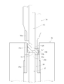
- FIG. 3 is a longitudinal sectional view taken along line EE of FIG. 3B, showing the inner joint member of FIG. 1.
- FIG. 3b is a right side view of the inner joint member of FIG. 3a.
- It is a longitudinal cross-sectional view of a raw material (billet), showing the forging process of the inner joint member of FIGS. 3a and 3b.
- a constant velocity universal joint and an inner joint member incorporating an inner joint member based on a forging method for an inner joint member of a constant velocity universal joint according to an embodiment of the present invention will be described with reference to FIGS.
- a constant velocity universal joint 1 shown in FIGS. 1 and 2 is a Rzeppa type constant velocity universal joint which is a fixed type constant velocity universal joint, and shows an example applied to a drive shaft for an automobile.
- the constant velocity universal joint 1 includes an outer joint member 2, an inner joint member 3, a torque transmission ball 4, and a cage 5.
- Six track grooves 7 are formed on the spherical inner peripheral surface 6 of the outer joint member 2 at equal intervals in the circumferential direction and along the axial direction.
- the groove bottom vertical section of the track groove 7 is formed in a curved shape.
- Track grooves 9 facing the track grooves 7 of the outer joint member 2 are formed on the spherical outer peripheral surface 8 of the inner joint member 3 at equal intervals in the circumferential direction and along the axial direction.
- the groove bottom vertical cross-sectional shape of the track groove 9 is formed in a curved shape.
- a female spline 12 is formed in the inner peripheral hole of the inner joint member 3, is fitted to a male spline 13 formed at the shaft end of the intermediate shaft 10, and is fixed in the axial direction by a retaining ring 14.
- the outer joint member 2 is integrally formed with a shaft portion 15 connected to a wheel bearing device (not shown).
- Grease as a lubricant is sealed inside the constant velocity universal joint 1.
- a bellows-like boot 11 is mounted between the outer joint member 2 of the constant velocity universal joint 1 and the intermediate shaft 10 in order to prevent external leakage of grease and entry of foreign matter from the outside of the joint. It is fastened and fixed by boot bands 16 and 17.
- the centers of curvature of the spherical inner peripheral surface 6 of the outer joint member 2 and the spherical outer peripheral surface 8 of the inner joint member 3 are both formed at the center O of the joint.
- the curvature center A of the curved groove bottom vertical section of the track groove 7 of the outer joint member 2 and the curvature center B of the curved groove bottom vertical section of the track groove 9 of the inner joint member 3 are: It is offset equidistantly in the axial direction with respect to the center O of the joint. For this reason, the track grooves 7 and 9 of the outer joint member 2 and the inner joint member 3 have a wedge shape that expands toward the opening side.
- FIG. 3a and 3b show a single view of the completed state of the inner joint member 3.
- FIG. 3a the center of curvature of the spherical outer peripheral surface 8 of the inner joint member 3 is located at the joint center O, and the center of curvature B of the groove bottom longitudinal section of the curved track groove 9 is offset from the joint center O in the axial direction. is doing.
- a female spline 12 is formed in the inner peripheral hole of the inner joint member 3.
- the notch 23 is for assembling the inner joint member 3 in the pocket 5a (see FIG. 1) of the retainer 5 when the inner joint member 3 is assembled to the retainer 5.
- the inner joint member 3 is made of chromium steel (for example, SCr420), chromium molybdenum steel (for example, SCM420) or the like, and a hardened layer is formed on the surface by heat treatment.
- the material (columnar billet) 30a shown in FIG. 4a is formed with a linear track groove 31 ′ and a spherical outer peripheral surface 34b in the outer peripheral portion, and the inner peripheral portion has a bottom. Holes 32a and 32b are formed on both sides in the axial direction, leaving the wall 33, thereby forming the raw material 30b.
- the columnar billet 30a is obtained by cutting a bar material into a predetermined dimension, and is subjected to annealing and surface lubrication treatment (for example, bondage treatment). Although this embodiment is cold forging, warm forging is also possible.
- the bottom wall 33 of the shaped member 30b is punched out by a hole punching process, and as shown in FIG. 4c, a hole 32c is formed to become the shaped member 30c.
- approximately half of the track groove 31 'of the shaped member 30c is formed into a curved track groove 31a as shown in FIG.
- the curved track groove 31a formed in the primary forming step is approximately half on the deep side of the track groove in consideration of forging processability and accuracy, but is not limited thereto. It may be approximately half of the shallow side.
- FIG. 5 is a longitudinal sectional view showing a forged state in the pre-forming step. The left half from the center axis of the billet or shaped material shows the state before pre-forming, and the right half shows the state after pre-forming.
- the forging die mainly includes a first inner diameter punch 35, a first end face punch 36, a second inner diameter punch 37, a second end face punch 38, and a preforming die 39.
- a convex molding surface 39a corresponding to the cross-sectional shape of the track groove is formed.
- a concave portion 36 a is formed on the outer peripheral surface of the first end surface punch 36, and a concave portion 38 a is formed on the outer peripheral surface of the second end surface punch 38.
- the concave portion 36a of the first end surface punch 36 and the concave portion 38a of the second end surface punch 38 are fitted to the convex molding surface 39a of the preforming die 39, respectively, and the first and second end surface punches 37 and 38 are respectively fitted.
- the end surface shape is a shape along the end surface shape of the shaped member 30b, and the end surface is formed as a flat surface.
- the first inner diameter punch 35 and the second inner diameter punch 37 are formed with curved surfaces that gently recede around the end surfaces, and the outer diameter surface of the tip portion is a cylinder parallel to the axis of the inner joint member (material). It is formed with a surface.
- the end surfaces of the first and second inner diameter punches 35 and 37 and the tip outer diameter surface are connected in a round shape.
- the first inner diameter punch 35, the first end face punch 36, and the second end face punch 38 are movable in the vertical direction in FIG. 5 by a driving device (not shown).
- the second inner diameter punch 37 and the preforming die 39 are fixed in the vertical direction of FIG.
- the cylindrical billet 30a is carried in as shown in the left half of FIG. Subsequently, the first inner diameter punch 35 and the first end face punch 36 advance downward in FIG. 5 to pressurize the billet 30a, and as shown in the right half of FIG.
- the spherical outer peripheral surface 34b and the concave portions 32a and 32b are formed to form the raw material 30b.
- a bottom wall 33 is formed between the recesses 32a and 32b in the base material 30b.
- the track groove 31 ' is formed in a straight line, so that the distance between the recesses 32a, 32b and the groove bottom of the track groove 31' on both axial end surfaces of the shaped member 30b is secured to the groove bottom. It is possible to form the deep recesses 32a and 32b having a large diameter while ensuring material satisfaction. Further, since the spherical outer peripheral surface 34b is molded without being constrained by the preforming die 39, it is possible to reduce the preforming load.
- the punch 36 is retracted upward in FIG.
- the second end face punch 38 advances upward in FIG. 5, and the raw material 30 b is discharged from the preforming die 39.
- FIG. 6 is a longitudinal sectional view showing the hole punching process, the left half from the central axis of the shaped members 30b and 30c shows the state before molding, and the right half shows the state after molding.
- the mold for the hole punching process mainly includes a first end surface retainer 40, a second end surface retainer 41, a punching punch 42, and an outer peripheral surface holding die 43.
- the first end surface retainer 40 and the second end surface retainer 41 are respectively movable in the vertical direction of FIG. 5 by a driving device (not shown).
- the punching punch 42 and the outer peripheral surface holding die 43 are fixed in the vertical direction in FIG.
- the punching punch 42 is provided with a tooth part 42a at the tip, and a tooth part 40a is provided on the inner peripheral part of the first end surface presser 40 corresponding to the tooth part 42a.
- the outer peripheral surface holding die 43 is also formed on the inner peripheral surface with a substantially half of the substantially spherical outer peripheral surface 34b of the shaped member 30b and a holding surface 43a for holding the linear track groove 31.
- the shaped member 30 b is carried onto the punching punch 42, and the first end face retainer 40 advances downward in the drawing and comes into contact with the end face of the shaped member 30 b. Subsequently, as shown in the right half of FIG. 6, the first end surface retainer 40 is advanced, and the bottom wall 33 of the shaped member 30b is punched out to obtain the shaped member 30c in which the hole 32c is formed. Since the linear track groove 31 ′ formed in the base material 30 b is highly rigid, a larger hole 32 c than in the conventional case can be extracted.
- the punched debris is sequentially fed into the inner peripheral hole of the first end surface retainer 40 and discharged to the outside from a release hole (not shown) provided in the middle of the inner peripheral hole. Thereafter, the first end surface retainer 40 is retracted upward in the drawing, the second end surface retainer 41 is advanced in the upward direction in the drawing, and the base material 30c is discharged.
- FIG. 7 is a longitudinal sectional view showing the primary molding process, with the left half from the central axis of the shaped members 30c and 30d showing the state before molding, and the right half showing the state after molding.
- the mold in the primary forming step mainly includes a first end face punch 44, a second end face punch 45, a tool pin 46, and a primary forming die 47.
- a shaped material 30d having substantially half of the axial direction on the inner peripheral surface of the primary forming die 47 having curved track grooves 31a and the other half having straight track grooves 31 ', these track grooves are formed.
- a concave portion 44 a is formed on the outer peripheral surface of the first end surface punch 44, and a concave portion 45 a is formed on the outer peripheral surface of the second end surface punch 45.
- the concave portion 44a of the first end surface punch 44 and the concave portion 45a of the second end surface punch 45 are fitted into the convex forming surface 47a of the die 47, respectively, and the end surfaces of the first and second end surface punches 44, 45 are fitted.
- the shape is a shape along the shape of the end face of the shaped member 30d.
- the tool pin 46 is fitted in the hole 32c of the base material 30c.
- the first end face punch 44 and the second end face punch 45 are movable in the vertical direction in FIG. 7 by a driving device (not shown).
- the tool pin 46 and the primary molding die 47 are fixed in the vertical direction of the drawing.
- the shaped material 30c is carried into the space between the primary forming die 47 and the tool pin 46.
- the first end face punch 44 advances downward in the drawing and abuts against the end face of the shaped member 30c.
- the first end face punch 44 advances, and as shown in the right half of FIG. A substantially half of the shape of the track groove 31 'on the lower side of the figure is formed into a curved track groove 31a, and a shape of the substantially half of the spherical outer peripheral surface 34d is maintained, so that a base material 30d is obtained.
- the spherical outer peripheral surface 34d only maintains a pre-formed spherical surface. For this reason, a spherical outer peripheral surface with a high yield rate is obtained. Further, since the tool pin 46 is inserted into the hole 32c of the shaped member 30c during molding, the inner peripheral shape of the hole 32c can be prevented from being collapsed, so that the machining allowance can be minimized and the track grooves 31a, 31 ′ can be minimized. The molding accuracy can be improved. After the molding, the first end surface punch 44 is retracted upward in the drawing, the second end surface punch 45 is advanced upward in the drawing, and the base material 30d is discharged.
- the curved track groove 31a formed in the primary forming step is approximately half on the deep side of the track groove in consideration of forging processability and accuracy. However, it is not limited to this, and may be approximately half on the shallow side of the track groove.
- FIG. 8 is a longitudinal sectional view showing the secondary forming process, in which the left half from the central axis of the shaped members 30d and 30e shows the state before forming, and the right half shows the state after forming.
- the mold in the secondary molding step is mainly composed of the first end surface punch 48, the second end surface punch 49, the tool pin 46 and the secondary molding die 50, as in the primary molding step.
- a curved and linear convex molding surface in contact therewith. 50a is formed on the inner peripheral surface of the secondary forming die 50.
- a concave portion 48 a is formed on the outer peripheral surface of the first end surface punch 48, and a concave portion 49 a is formed on the outer peripheral surface of the second end surface punch 49.
- the concave portion 48 a of the first end surface punch 48 and the concave portion 49 a of the second end surface punch 49 are fitted into the convex molding surface 50 a of the secondary molding die 50.
- the tool pin 46 is fitted in the hole 32c of the base material 30d.
- the first end face punch 48 and the second end face punch 49 are respectively movable in the vertical direction of FIG. 8 by a driving device (not shown), and the tool pin 46 and the secondary forming die 50 are fixed in the vertical direction of the drawing. ing.
- the shaped material 30d is carried into the space between the secondary forming die 50 and the tool pin 46.
- the first end face punch 48 advances downward in the drawing and abuts against the end face of the raw material 30d, and then the first end face punch 48 advances and the drawing of the raw material 30d as shown in the right half of FIG.
- a substantially half straight track groove 31 ′ on the lower side is formed into a curved track groove 31b and the shape of the spherical outer peripheral surface 34e is maintained, and a forged product 30e is obtained.
- the secondary forming step only the track groove 31 'is formed, and the spherical outer peripheral surface 34e only maintains a pre-formed spherical surface. For this reason, a spherical outer peripheral surface with a high yield rate is obtained.
- the inner peripheral shape of the hole 32c can be prevented from collapsing, so that the machining allowance can be minimized and the molding accuracy of the track groove 31b can be minimized. Can be improved.
- the first end surface punch 48 is retracted upward in the drawing, the second end surface punch 49 is advanced in the upper direction of the drawing, and the forged product 30e is discharged.
- the width surface and the outer diameter surface are turned, and the spline is broached on the inner diameter surface. Thereafter, heat treatment such as carburizing and quenching is performed to grind the spherical outer diameter surface and the track groove, and the inner joint member 3 shown in FIG. 3 is completed.
- a substantially half curved track groove 61a and a spherical outer peripheral surface 64a are formed from the billet in the axial direction, and the remaining substantially half in the axial direction is formed as a straight track groove 61b and a substantially linear outer peripheral surface. 64b.
- the mold (primary molding die) 71 At the time of molding, as described above with reference to FIG. 13, almost the entire outer peripheral surface of the shaped member 60 b is constrained by the mold (primary molding die) 71, becoming close to a hermetically sealed state. It becomes a stress state. For this reason, the deformation
- the mold 71 has a structure having a molding surface of the upper linear track groove 61b and a molding surface of the lower curved track groove 61a, the groove bottom and the hole of the curved track groove 61a on the lower end surface.
- the distance L1 of 62a becomes narrow, the diameter G1 of the hole 62a becomes small, and the depth H1 becomes shallow. For this reason, it is difficult to reduce the allowance for inner diameter.
- the present embodiment has a characteristic configuration in which a pre-molding process that bears most of the deformation amount of the primary molding process is provided, and only the track grooves are molded in the primary molding process.
- a linear track groove 31 ′ and a spherical outer peripheral surface 34 are formed from the billet over the entire length in the axial direction.
- the spherical outer peripheral surface 34 is molded without being constrained by the preforming die 39, so that the preforming load can be reduced. For this reason, there is little deformation of the preforming die 39, and the track groove 31 'can be formed with high accuracy.
- the linear track groove 31 ' is formed from the billet over the entire length in the axial direction, the distance L2 between the groove bottom of the linear track groove 31' on the lower end surface and the hole 32a is increased, and the diameter G2 of the hole 32a is increased. And the depth H2 can be increased. For this reason, the allowance for inner diameter can be reduced.
- the bottom wall 33 of the base material 30b is punched, and then only the track grooves are formed in the primary molding and the secondary molding, so that the molding load can be reduced, the molding die 47, The degree of deformation of 50 can be reduced and the track groove can be formed with high accuracy. Further, only the track grooves are formed in the primary molding and the secondary molding, and the spherical outer peripheral surface is merely maintained in the preformed shape, so that a spherical outer peripheral surface shape with a high yield can be obtained.
- FIG. 10 A conventional forged product is shown on the left half from the central axis of FIG. 10, and a forged product of this embodiment is shown on the right half.
- Both the conventional forged product 60d and the forged product 30e of the present embodiment have the same outer diameter of the spherical outer peripheral surface D, but the spherical outer peripheral surface 64d of the conventional forged product 60d has an axial direction. There is a straight part at the center.
- the spherical outer peripheral surface 34e of the forged product 30e of the present embodiment has almost no linear portion and is formed into a shape close to a spherical surface.
- the diameter Db1 0.94D of the spherical outer peripheral surface 64d of the conventional forged product 60d on the upper side of the drawing
- the diameter Db2 0.88D of the spherical outer peripheral surface 34e of the forged product 30e of the present embodiment.
- the allowance for the spherical outer peripheral surface 34e of the forged product 30e of the present embodiment is significantly smaller than the allowance for the spherical outer peripheral surface 64d of the conventional forged product 60d, and a spherical outer peripheral surface 34e having a high yield rate is obtained. .
- the removal allowance of the hole 32c of the forged product 30e of the present embodiment is significantly smaller than the allowance of the hole 62c of the conventional forged product 60d, and the shape of the inner diameter surface including the hole 32c having a high yield rate. Dimensions are obtained. This is because the track groove 31 is linearly formed in the preforming step, so that the distance between the concave portions 32a, 32b and the groove bottom portion of the track groove 31 ′ on the both end surfaces in the axial direction of the shaped member 30b is secured.
- the linear track groove 31 'of the shaped member 30b is highly rigid, so that This is also because the large hole 32c can be removed.
- the forged product based on the forging method of the present embodiment was able to improve the yield rate by about 6% compared to the forged product based on the conventional forging method. Furthermore, although the specific numerical comparison is omitted, the forming accuracy of the track groove 31 is improved.
- the forging method of the present embodiment has a preforming step added compared to the conventional forging method, but the manufacturing cost is lower than the conventional forging method as a whole, including post-processing, by reducing the machining allowance and improving the yield rate. Can be reduced.
- Table 1 shows the molding loads of the conventional forging method and the forging method of this embodiment.
- Table 1 shows the molding loads of the conventional forging method and the forging method of this embodiment.
- the process with the highest molding load among the primary molding process and the secondary molding process was defined as the reference F1.
- forging was possible with a load of 55% of the total forming load of the conventional forging method.
- the forming load F1 in the primary forming step showed an extremely high load, but in the forging method of the present embodiment, it could be reduced to about 1 ⁇ 2 of the peak load of the conventional forging method.
- a conical surface 37a ′ having a slight draft angle is formed on the outer diameter portion of the second inner diameter punch 37 ′ for forming the hole portion 32a ′ of the base material 30b ′.
- the hole portion 32b ′ is formed.
- a conical surface 35a ′ having a slight taper is formed on the outer diameter portion of the tip of the first inner diameter punch 35 ′.
- the shape of the hole (the shape of the outer diameter surface of the tip of the inner diameter punch) can be a cylindrical surface parallel to the axis of the inner joint member (shape member) as in the above-described embodiment, or can be light as in this modification.
- a conical surface with a draft gradient By using a conical surface with a draft gradient, the moldability and mold release property can be adjusted as appropriate.
- Conical surfaces 36b 'and 38b' having a slight taper angle are formed on the end surfaces of the first end surface punch 36 'and the second end surface punch 38' that pressurize and mold both end surfaces of the raw material 30b '. Is formed. In this case, the end faces of the first end face retainer 40, the end face punches 44, 48 and the second end face retainer 41, the end face punches 45, 49 in the hole punching process, the primary forming process and the secondary forming process remain flat. It is.
- the conical surfaces 36b 'and 38b' having a light taper on the end surfaces of the first end surface punch 36 'and the second end surface punch 38', the formability in the primary molding process and the secondary molding process is improved. . Formability can be improved by making both axial end faces (end faces of the end face retainer) flat surfaces as in the above-described embodiment or conical faces having a slight taper angle as in this modification. It can be adjusted appropriately.
- the convex forming surface 39a ′ of the preforming die 39 ′ for forming the linear track groove 31 ′′ is formed in a tapered shape with a slight draft angle. Thereby, the mold releasability of the base material 30b ′.
- a straight track groove (projection forming surface) is made parallel to the axis of the inner joint member (raw material) as in the above-described embodiment, or a taper shape with a drop gradient as in this modification. By making it, moldability and mold release property can be adjusted as appropriate.
- the inner joint member of the constant velocity universal joint constituting the drive shaft is exemplified, but the present invention can also be applied to the inner joint member of the constant velocity universal joint constituting the propeller shaft.
Abstract
Provided is a forging method for an inner joint member (3) of a constant-velocity universal joint (1) that comprises the following: an outer joint member (2) in which a plurality of track grooves (7), the grooved-bottom vertical cross-section of which has a curved shape, are formed along the axial direction in a spherical inner-circumferential surface (6) of the outer joint member; an inner joint member (3) in which a plurality of track grooves (9), the grooved-bottom vertical cross-section of which has a curved shape, are formed along the axial direction in a spherical outer-circumferential surface (8) of the inner joint member, in opposition to the track grooves (7) of the outer joint member (2); torque transmitting balls (4) which are fit between the opposing track grooves (7, 9); and a retainer (5) in which the torque transmitting balls (4) are retained and which is guided by the spherical inner-circumferential surface (6) of the outer joint member (2) and the spherical outer-circumferential surface (8) of the inner joint member (3). The forging method is characterized by comprising the following: a preliminary molding step for forming, from a cylindrical billet (30a), a semi-finished product (30b, 30b') in which on both sides in the axial direction hole sections (32a, 32b, 32a', 32b') are formed in such a manner that a linear track groove (31', 31") on an outer circumferential section and bottom walls (33, 33') on an inner circumferential section remain; a hole punching step for, following the preliminary molding step, punching the bottom walls (33, 33') of the semi-finished product (30b, 30b'); a primary molding step for, following the hole punching step, forming a curved track groove (31a) in substantially half of the axial direction of the semi-finished product (30c); and a secondary molding step for, following the primary molding step, inverting the axial direction ends of the semi-finished product (30d) and forming a curved track groove (31b) in the remaining substantially-half of the axial direction of such semi-finished product (30d).
Description
この発明は、トラック溝の溝底縦断面形状が曲線状とされた等速自在継手、いわゆる、ツェッパ型等速自在継手の内側継手部材の鍛造方法に関する。
The present invention relates to a method for forging an inner joint member of a constant velocity universal joint in which the groove bottom longitudinal section shape of a track groove is a curved shape, a so-called Zepper type constant velocity universal joint.
自動車や各種産業機械の動力伝達系を構成する等速自在継手は、駆動側と従動側の二軸をトルク伝達可能に連結すると共に、前記二軸が作動角をとっても等速で回転トルクを伝達することができる。等速自在継手は、角度変位のみを許容する固定式等速自在継手と、角度変位および軸方向変位の両方を許容する摺動式等速自在継手とに大別され、例えば、自動車のエンジンから駆動車輪に動力を伝達するドライブシャフトにおいては、デフ側(インボード側)に摺動式等速自在継手が使用され、駆動車輪側(アウトボード側)には固定式等速自在継手が使用される。
The constant velocity universal joint that constitutes the power transmission system of automobiles and various industrial machines connects the two shafts on the drive side and the driven side so that torque can be transmitted, and transmits rotational torque at a constant speed even if the two shafts have an operating angle. can do. Constant velocity universal joints are broadly classified into fixed constant velocity universal joints that allow only angular displacement and sliding constant velocity universal joints that allow both angular displacement and axial displacement. In the drive shaft that transmits power to the drive wheel, a sliding type constant velocity universal joint is used on the differential side (inboard side), and a fixed type constant velocity universal joint is used on the drive wheel side (outboard side). The
ツェッパ型等速自在継手は、球状内周面に溝底縦断面形状が曲線状の複数のトラック溝が軸方向に沿って形成された外側継手部材と、球状外周面に溝底縦断面形状が曲線状の複数のトラック溝が前記外側継手部材のトラック溝に対向して軸方向に沿って形成された内側継手部材と、対向する各トラック溝間に組込まれたトルク伝達ボールと、このトルク伝達ボールを保持し、前記外側継手部材の球状内周面と前記内側継手部材の球状外周面に案内される保持器とからなる。ツェッパ型等速自在継手は、前述した角度変位のみを許容する固定式等速自在継手に属する。
The Rzeppa constant velocity universal joint has an outer joint member in which a plurality of track grooves having a curved groove bottom longitudinal section shape are formed along the axial direction on a spherical inner peripheral surface, and a groove bottom vertical sectional shape on a spherical outer peripheral surface. An inner joint member in which a plurality of curved track grooves are formed along the axial direction so as to face the track grooves of the outer joint member, a torque transmission ball incorporated between the opposed track grooves, and the torque transmission It comprises a cage that holds the ball and is guided by the spherical inner peripheral surface of the outer joint member and the spherical outer peripheral surface of the inner joint member. The Rzeppa constant velocity universal joint belongs to the fixed type constant velocity universal joint that allows only the angular displacement described above.
この等速自在継手の内側継手部材の従来の鍛造方法を図12および図13に示す。図12aに示す素材(円柱状ビレット)60aを一次成形工程により、図12bに示すように、外周部の軸方向の略半分に曲線状トラック溝61aを形成し、軸方向の残り半分を直線状トラック溝61bに成形する。内周部には、底壁63を残して軸方向両側に穴部62a、62bを形成する。その後、素形材60bの軸方向両端を反転させて、二次成形工程により、図12cに示すように、素形材60bの略半分の直線状トラック溝61bを曲線状トラック溝61cに成形し、曲線状トラック溝61を備えた素形材60cを得る。その後、穴抜き工程により、図12dに示すように、底壁63を打ち抜いて穴62cを形成し、鍛造品が完成する(特許文献1参照)。
A conventional forging method for the inner joint member of this constant velocity universal joint is shown in FIGS. The material (columnar billet) 60a shown in FIG. 12a is formed in a primary forming step to form a curved track groove 61a in approximately half of the outer peripheral portion in the axial direction, and the other half in the axial direction is linear. The track groove 61b is formed. Holes 62a and 62b are formed on both sides in the axial direction, leaving the bottom wall 63 on the inner periphery. Thereafter, both ends of the raw material 60b in the axial direction are reversed, and a linear track groove 61b, which is substantially half of the raw material 60b, is formed into a curved track groove 61c by a secondary forming step as shown in FIG. 12c. Then, the base material 60c provided with the curved track groove 61 is obtained. Thereafter, as shown in FIG. 12d, a bottom wall 63 is punched out to form a hole 62c by a hole punching process, and a forged product is completed (see Patent Document 1).
従来の鍛造方法では、図13に示すように、一次成形工程において、上側ポンチ70の下死点時、素形材60bの外周面の一部以外は、ほぼ全面が金型71に拘束され、密閉に近い状態になる。そのために、金型71と素形材60bは高圧となり金型71に悪影響を及ぼす高応力状態となり、同時に、高応力状態のため金型71の変形が大きく、トラック溝61a、61bの成形精度が悪化する。すなわち、金型71の寿命向上および鍛造品の精度向上のために、一次成形の荷重を低減させる必要があることが判明した。
In the conventional forging method, as shown in FIG. 13, in the primary forming step, at the bottom dead center of the upper punch 70, almost the entire surface except for a part of the outer peripheral surface of the shaped member 60b is restrained by the mold 71, It becomes a state close to sealing. Therefore, the mold 71 and the raw material 60b are in a high stress state that has a high pressure and adversely affects the mold 71. At the same time, the deformation of the mold 71 is large due to the high stress state, and the molding accuracy of the track grooves 61a and 61b is high. Getting worse. That is, it has been found that it is necessary to reduce the primary molding load in order to improve the life of the die 71 and the accuracy of the forged product.
一方、鍛造品の材料歩留り率を高めるために、均一な切削代が望ましい。ツェッパ型等速自在継手の内側継手部材の場合では、製品の外周面が球面で、曲線状トラック溝61は軸方向両端で溝深さが異なり、内径面が円筒状である。理想的な鍛造品は、外周面が赤道面を中心とする上下対称な球面、軸方向両端で溝深さが異なる曲線状トラック溝61で、内周面が製品の内径寸法に近い形状を有することである。鍛造完了時に金型から離型させるために、固定式ダイスを用いる従来の鍛造方法では、金型(一次成形ダイス)71は上部の直線状トラック溝61bの成形面と下部の曲線状トラック溝61aの成形面を有する構造となっている。この場合、下端面のトラック溝61aと穴部62aの距離が狭く充足が困難であり、特に下端面の曲線状トラック溝61aの溝底部が最も充足し難い位置であることが判明した。下端面の曲線状トラック溝61aの溝底部を充足させるためには、下側ポンチ72の穴部62aの成形面を小さくし、穴部62aを小さく浅い形状にする必要があり、その結果、一次成形工程の鍛造品の形状は上端部が肥大化した非対称形状にならざるを得ないことが判明した。
On the other hand, a uniform cutting allowance is desirable in order to increase the material yield rate of forged products. In the case of the inner joint member of the Rzeppa constant velocity universal joint, the outer peripheral surface of the product is a spherical surface, the curved track groove 61 has a groove depth different at both axial ends, and the inner surface is cylindrical. An ideal forged product is a spherical surface that is symmetrical in the vertical direction with the outer peripheral surface being centered on the equator surface, and a curved track groove 61 having different groove depths at both axial ends, and the inner peripheral surface has a shape close to the inner diameter of the product. That is. In the conventional forging method using a fixed die in order to release the mold from the mold when the forging is completed, the mold (primary molding die) 71 has a molding surface of the upper linear track groove 61b and a lower curved track groove 61a. It has a structure having a molding surface. In this case, it has been found that the distance between the track groove 61a on the lower end surface and the hole 62a is narrow and is difficult to satisfy, and in particular, the groove bottom of the curved track groove 61a on the lower end surface is the most difficult position. In order to satisfy the groove bottom portion of the curved track groove 61a on the lower end surface, it is necessary to reduce the molding surface of the hole 62a of the lower punch 72 and make the hole 62a small and shallow, and as a result, the primary It became clear that the shape of the forged product in the forming process had to be an asymmetric shape with an enlarged upper end.
さらに、従来の鍛造方法は、前述したように、二次成形工程後に底壁63を打ち抜く。その際、成形された曲線状トラック溝61の精度が悪化する恐れがある。曲線状トラック溝61の精度を維持するために内径部の剛性を高める必要があり、この面からも従来の鍛造方法では内径部の取り代を少なくする直径の大きな穴部62aを鍛造することが困難であることが判明した。
Furthermore, in the conventional forging method, as described above, the bottom wall 63 is punched after the secondary forming step. At this time, the accuracy of the formed curved track groove 61 may be deteriorated. In order to maintain the accuracy of the curved track groove 61, it is necessary to increase the rigidity of the inner diameter portion. From this surface as well, the conventional forging method can forge the hole portion 62a having a large diameter that reduces the allowance for the inner diameter portion. It turned out to be difficult.
上記のような問題に鑑み、本発明は、成形時の面圧を低減して金型の変形程度を軽減し、高精度なトラック溝の成形を可能とし、かつ、材料歩留りが高い等速自在継手の内側継手部材の鍛造方法を提供することを目的とする。
In view of the above problems, the present invention reduces the surface pressure at the time of molding, reduces the degree of deformation of the mold, enables the formation of a highly accurate track groove, and has a high material yield. An object of the present invention is to provide a method for forging an inner joint member of a joint.
本発明者らは、上記の目的を達成するために種々検討した結果、一次成形工程の成形変形量の大半を負担する予備成形工程を設け、一次成形工程ではトラック溝のみを成形するという新たな着想を行い、本発明に至った。
As a result of various studies to achieve the above object, the present inventors have provided a preforming process that bears most of the deformation amount of the primary forming process, and in the primary forming process, a new technique of forming only the track grooves is provided. The idea was made and the present invention was achieved.
前述の目的を達成するための技術的手段として、本発明は、球状内周面に溝底縦断面形状が曲線状の複数のトラック溝が軸方向に沿って形成された外側継手部材と、球状外周面に溝底縦断面形状が曲線状の複数のトラック溝が前記外側継手部材のトラック溝に対向して軸方向に沿って形成された内側継手部材と、対向する各トラック溝間に組込まれたトルク伝達ボールと、このトルク伝達ボールを保持し、前記外側継手部材の球状内周面と前記内側継手部材の球状外周面に案内される保持器とからなる等速自在継手の内側継手部材の鍛造方法において、前記鍛造方法は、円柱状ビレットから、外周部に直線状のトラック溝部と内周部に底壁を残して軸方向両側に穴部を成形した素形材を形成する予備成形工程と、前記素形材の前記底壁を打ち抜く穴抜き工程と、前記穴抜き工程後、前記素形材の軸方向の略半分に曲線状のトラック溝を形成する一次成形工程と、前記一次成形工程の後、前記素形材の軸方向両端を反転させて、軸方向の残り略半分に曲線状のトラック溝を形成する二次成形工程を備えていることを特徴とする。
As technical means for achieving the above-mentioned object, the present invention includes an outer joint member in which a plurality of track grooves having a curved groove bottom longitudinal cross-sectional shape formed along the axial direction on a spherical inner peripheral surface, and a spherical shape. A plurality of track grooves having a curved groove bottom vertical cross-sectional shape on the outer peripheral surface are incorporated between the inner joint member formed along the axial direction so as to face the track grooves of the outer joint member, and between the opposed track grooves. An inner joint member of a constant velocity universal joint comprising a torque transmission ball and a cage that holds the torque transmission ball and is guided by a spherical inner peripheral surface of the outer joint member and a spherical outer peripheral surface of the inner joint member. In the forging method, the forging method is a pre-forming step of forming a shaped material in which holes are formed on both sides in the axial direction, leaving a linear track groove portion on the outer peripheral portion and a bottom wall on the inner peripheral portion from the cylindrical billet. And hitting the bottom wall of the shaped material A punching step for punching, a primary forming step for forming a curved track groove in substantially half of the axial direction of the shaped material after the punching step, and an axial direction of the shaped material after the primary forming step A secondary forming step is provided in which both ends are reversed and a curved track groove is formed in substantially the other half in the axial direction.
上記の構成により、成形時の面圧を低減して金型の変形程度を軽減し、高精度なトラック溝の成形を可能とし、かつ、材料歩留りが高い等速自在継手の内側継手部材の鍛造方法を実現することができる。
With the above configuration, the surface pressure during molding is reduced, the degree of deformation of the mold is reduced, high-precision track groove molding is possible, and the inner joint member of a constant velocity universal joint with high material yield is forged. A method can be realized.
上記の予備成形工程の直線状のトラック溝を、内側継手部材の軸線に平行、あるいは軽度の抜き勾配のあるテーパ状にすることにより、成形性や離型性を適宜調整することができる。
Formability and releasability can be appropriately adjusted by making the linear track groove in the preforming step parallel to the axis of the inner joint member or having a slight draft angle.
上記の予備成形工程で素形材の軸方向両側に形成する穴部を、内側継手部材の軸線に平行な円筒面、あるいは軽度の抜き勾配のある円錐面にすることにより、成形性や離型性を適宜調整することができる。
By forming the holes formed on both sides in the axial direction of the shaped material in the above preforming process into a cylindrical surface parallel to the axis of the inner joint member or a conical surface with a slight draft, moldability and mold release The property can be adjusted as appropriate.
上記の予備成形工程で成形された素形材の軸方向両端面を、平坦面、あるいは軽度のテーパ角を有する円錐面にすることにより、成形性を適宜調整することができる。
The formability can be appropriately adjusted by making both end surfaces in the axial direction of the shaped material formed in the above-mentioned preforming step into flat surfaces or conical surfaces having a slight taper angle.
上記の一次成形工程と二次成形工程の少なくとも一方の成形工程において、曲線状のトラック溝を成形する際に、穴抜き工程により打ち抜いた穴の内径面に工具ピンを挿入することが好ましい。これにより、穴の内周形状の崩れを防止できるので、取り代を極小化でき、トラック溝の成形精度を向上させることができる。
In the forming step of at least one of the primary forming step and the secondary forming step, it is preferable to insert a tool pin into the inner diameter surface of the hole punched by the punching step when forming the curved track groove. Thereby, the collapse of the inner peripheral shape of the hole can be prevented, so that the machining allowance can be minimized and the forming accuracy of the track groove can be improved.
上記の一次成形工程において、素形材の軸方向の略半分に形成する曲線状のトラック溝を溝深さの深い側のトラック溝とすることにより、鍛造加工性や精度などの面から有利となる。
In the primary forming step described above, the curved track groove formed in approximately half of the axial direction of the base material is a track groove on the deeper groove depth side, which is advantageous from the viewpoint of forging processability and accuracy. Become.
本発明によれば、成形時の面圧を低減して金型の変形程度を軽減し、高精度なトラック溝の成形を可能とし、かつ、材料歩留りが高い等速自在継手の内側継手部材の鍛造方法を実現することができる。
According to the present invention, the surface pressure at the time of molding is reduced, the degree of deformation of the mold is reduced, the track groove can be formed with high accuracy, and the inner joint member of the constant velocity universal joint with a high material yield is obtained. A forging method can be realized.
以下に本発明の実施の形態を図面に基づいて説明する。
Embodiments of the present invention will be described below with reference to the drawings.
本発明の一実施形態に係る等速自在継手の内側継手部材の鍛造方法に基づく内側継手部材を組み込んだ等速自在継手および内側継手部材を図1~図3に基づいて説明する。図1および図2に示す等速自在継手1は固定式等速自在継手であるツェッパ型等速自在継手で、自動車用ドライブシャフトに適用した例を示す。
A constant velocity universal joint and an inner joint member incorporating an inner joint member based on a forging method for an inner joint member of a constant velocity universal joint according to an embodiment of the present invention will be described with reference to FIGS. A constant velocity universal joint 1 shown in FIGS. 1 and 2 is a Rzeppa type constant velocity universal joint which is a fixed type constant velocity universal joint, and shows an example applied to a drive shaft for an automobile.
図1および図2に示すように、等速自在継手1は、外側継手部材2、内側継手部材3、トルク伝達ボール4および保持器5からなる。外側継手部材2の球状内周面6には6本のトラック溝7が円周方向等間隔に、かつ軸方向に沿って形成されている。トラック溝7の溝底縦断面形状は曲線状に形成されている。内側継手部材3の球状外周面8には、外側継手部材2のトラック溝7と対向するトラック溝9が円周方向等間隔に、かつ軸方向に沿って形成されている。トラック溝9の溝底縦断面形状は曲線状に形成されている。外側継手部材2のトラック溝7と内側継手部材3のトラック溝9との間にトルクを伝達する6個のボール4が1個ずつ組み込まれている。外側継手部材2の球状内周面6と内側継手部材3の球状外周面8の間に、ボール4をポケット5aに保持する保持器5が配置され、球状内周面6、球状外周面8に案内されている。
1 and 2, the constant velocity universal joint 1 includes an outer joint member 2, an inner joint member 3, a torque transmission ball 4, and a cage 5. Six track grooves 7 are formed on the spherical inner peripheral surface 6 of the outer joint member 2 at equal intervals in the circumferential direction and along the axial direction. The groove bottom vertical section of the track groove 7 is formed in a curved shape. Track grooves 9 facing the track grooves 7 of the outer joint member 2 are formed on the spherical outer peripheral surface 8 of the inner joint member 3 at equal intervals in the circumferential direction and along the axial direction. The groove bottom vertical cross-sectional shape of the track groove 9 is formed in a curved shape. Six balls 4 for transmitting torque are incorporated one by one between the track groove 7 of the outer joint member 2 and the track groove 9 of the inner joint member 3. Between the spherical inner peripheral surface 6 of the outer joint member 2 and the spherical outer peripheral surface 8 of the inner joint member 3, a cage 5 that holds the ball 4 in the pocket 5 a is disposed, and the spherical inner peripheral surface 6 and the spherical outer peripheral surface 8 are arranged. Guided.
トラック溝7、9とボール4は、通常、接触角(30°~45°程度)をもって接触しているので、トラック溝7、9とボール4とは、実際にはトラック溝7、9の溝底より少し離れたトラック溝7、9の側面側の位置で接触している。内側継手部材3の内周孔には雌スプライン12が形成されており、中間シャフト10の軸端に形成された雄スプライン13に嵌合され、止め輪14により軸方向に固定されている。外側継手部材2には、車輪用軸受装置(図示省略)に接続される軸部15が一体に形成されている。
Since the track grooves 7 and 9 and the ball 4 are normally in contact with each other at a contact angle (about 30 ° to 45 °), the track grooves 7 and 9 and the ball 4 are actually grooves of the track grooves 7 and 9. Contact is made at a position on the side surface side of the track grooves 7 and 9 that are slightly apart from the bottom. A female spline 12 is formed in the inner peripheral hole of the inner joint member 3, is fitted to a male spline 13 formed at the shaft end of the intermediate shaft 10, and is fixed in the axial direction by a retaining ring 14. The outer joint member 2 is integrally formed with a shaft portion 15 connected to a wheel bearing device (not shown).
等速自在継手1の内部には潤滑剤としてのグリースが封入されている。グリースの外部漏洩や継手外部からの異物侵入を防止するため、等速自在継手1の外側継手部材2と中間シャフト10との間には、蛇腹状のブーツ11が装着され、ブーツ11の両端はブーツバンド16、17により締め付け固定されている。
Grease as a lubricant is sealed inside the constant velocity universal joint 1. A bellows-like boot 11 is mounted between the outer joint member 2 of the constant velocity universal joint 1 and the intermediate shaft 10 in order to prevent external leakage of grease and entry of foreign matter from the outside of the joint. It is fastened and fixed by boot bands 16 and 17.
外側継手部材2の球状内周面6と内側継手部材3の球状外周面8の曲率中心は、いずれも、継手の中心Oに形成されている。これに対して、外側継手部材2のトラック溝7の曲線状の溝底縦断面の曲率中心Aと、内側継手部材3のトラック溝9の曲線状の溝底縦断面の曲率中心Bとは、継手の中心Oに対して軸方向に等距離オフセットされている。このため、外側継手部材2と内側継手部材3のトラック溝7、9は開口側に向けて拡がる楔状をなしている。このような構成により、継手が作動角をとった場合、外側継手部材2と内側継手部材3の両軸線がなす角度を二等分する平面上にボール4が常に案内され、二軸間で等速に回転トルクが伝達されることになる。
The centers of curvature of the spherical inner peripheral surface 6 of the outer joint member 2 and the spherical outer peripheral surface 8 of the inner joint member 3 are both formed at the center O of the joint. On the other hand, the curvature center A of the curved groove bottom vertical section of the track groove 7 of the outer joint member 2 and the curvature center B of the curved groove bottom vertical section of the track groove 9 of the inner joint member 3 are: It is offset equidistantly in the axial direction with respect to the center O of the joint. For this reason, the track grooves 7 and 9 of the outer joint member 2 and the inner joint member 3 have a wedge shape that expands toward the opening side. With such a configuration, when the joint takes an operating angle, the ball 4 is always guided on a plane that bisects the angle formed by the two axes of the outer joint member 2 and the inner joint member 3, and so on. Rotational torque is transmitted at high speed.
内側継手部材3の完成状態の単体図を図3aおよび図3bに示す。図3aに示すように、内側継手部材3の球状外周面8の曲率中心は継手中心Oに位置し、曲線状トラック溝9の溝底縦断面の曲率中心Bは継手中心Oから軸方向にオフセットしている。内側継手部材3の内周孔には雌スプライン12が形成されている。切欠き部23は、保持器5に内側継手部材3を組み立てる際に、保持器5のポケット5a(図1参照)に内側継手部材3を潜らせて組み立てるためのものである。内側継手部材3は、クロム鋼(例えば、SCr420)やクロムモリブデン鋼(例えば、SCM420)等からなり、表面には熱処理による硬化層が形成されている。
3a and 3b show a single view of the completed state of the inner joint member 3. FIG. 3a, the center of curvature of the spherical outer peripheral surface 8 of the inner joint member 3 is located at the joint center O, and the center of curvature B of the groove bottom longitudinal section of the curved track groove 9 is offset from the joint center O in the axial direction. is doing. A female spline 12 is formed in the inner peripheral hole of the inner joint member 3. The notch 23 is for assembling the inner joint member 3 in the pocket 5a (see FIG. 1) of the retainer 5 when the inner joint member 3 is assembled to the retainer 5. The inner joint member 3 is made of chromium steel (for example, SCr420), chromium molybdenum steel (for example, SCM420) or the like, and a hardened layer is formed on the surface by heat treatment.
次に、本発明の一実施形態に係る等速自在継手の内側継手部材の鍛造方法の概要を図4a~図4eに基づいて説明する。図4aに示す素材(円柱状ビレット)30aを予備成形工程により、図4bに示すように、外周部に直線状のトラック溝31’と球状外周面34bを形成し、内周部には、底壁33を残して軸方向両側に穴部32a、32bを形成し素形材30bとなる。円柱状ビレット30aは、バー材を所定寸法に切断したもの等であり、焼鈍および表面潤滑処理(例えば、ボンデ処理)が施されている。本実施形態は冷間鍛造であるが、温間鍛造も可能である。
Next, an outline of a forging method for the inner joint member of the constant velocity universal joint according to the embodiment of the present invention will be described with reference to FIGS. 4a to 4e. As shown in FIG. 4b, the material (columnar billet) 30a shown in FIG. 4a is formed with a linear track groove 31 ′ and a spherical outer peripheral surface 34b in the outer peripheral portion, and the inner peripheral portion has a bottom. Holes 32a and 32b are formed on both sides in the axial direction, leaving the wall 33, thereby forming the raw material 30b. The columnar billet 30a is obtained by cutting a bar material into a predetermined dimension, and is subjected to annealing and surface lubrication treatment (for example, bondage treatment). Although this embodiment is cold forging, warm forging is also possible.
その後、穴抜き工程により素形材30bの底壁33を打ち抜いて、図4cに示すように、穴32cを形成し素形材30cとなる。続いて、一次成形工程により、素形材30cのトラック溝31’の略半分を、図4dに示すように、曲線状のトラック溝31aに成形し素形材30dとなる。
Thereafter, the bottom wall 33 of the shaped member 30b is punched out by a hole punching process, and as shown in FIG. 4c, a hole 32c is formed to become the shaped member 30c. Subsequently, in the primary forming step, approximately half of the track groove 31 'of the shaped member 30c is formed into a curved track groove 31a as shown in FIG.
素形材30dの軸方向両端を反転させ、素形材30dの残り略半分のトラック溝31’を、図4eに示すように、曲線状のトラック溝31bに成形しトラック溝31を有する鍛造完了品30eとなる。
The both ends in the axial direction of the shaped member 30d are reversed, and the forging process is completed by forming the remaining substantially half of the track groove 31 ′ of the shaped member 30d into a curved track groove 31b as shown in FIG. 4E. Product 30e.
本実施形態では、一次成形工程において成形する曲線状のトラック溝31aは、鍛造加工性や精度などを考慮して、トラック溝の深い側の略半分としたが、これに限られず、トラック溝の浅い側の略半分としてもよい。
In the present embodiment, the curved track groove 31a formed in the primary forming step is approximately half on the deep side of the track groove in consideration of forging processability and accuracy, but is not limited thereto. It may be approximately half of the shallow side.
次に、本実施形態に係る内側継手部材の具体的な鍛造方法を図5~図8に基づいて説明する。本実施形態の鍛造方法は鍛造機としてフォーマー(横型多段式鍛造機)を適用した例を示す。この場合、図5~図8の紙面は水平方向となる。図5は予備成形工程の鍛造状態を示す縦断面図で、ビレットあるいは素形材の中心軸線から左側半分は予備成形前の状態を示し、右側半分は予備成形後の状態を示す。
Next, a specific forging method for the inner joint member according to the present embodiment will be described with reference to FIGS. The forging method of this embodiment shows an example in which a former (horizontal multistage forging machine) is applied as a forging machine. In this case, the planes of FIGS. 5 to 8 are horizontal. FIG. 5 is a longitudinal sectional view showing a forged state in the pre-forming step. The left half from the center axis of the billet or shaped material shows the state before pre-forming, and the right half shows the state after pre-forming.
図5に示すように、鍛造金型は、第1の内径ポンチ35、第1の端面ポンチ36、第2の内径ポンチ37、第2の端面ポンチ38および予備成形ダイス39を主な構成とする。予備成形ダイス39の内周面には、トラック溝の横断面形状に対応する凸状成形面39aが形成されている。第1の端面ポンチ36の外周面には凹状部36aが形成され、第2の端面ポンチ38の外周面には凹状部38aが形成されている。第1の端面ポンチ36の凹状部36aと第2の端面ポンチ38の凹状部38aは、予備成形ダイス39の凸状成形面39aにそれぞれ嵌合し、第1および第2の端面ポンチ37、38の端面形状は素形材30bの端面形状に沿った形状になっており、端面は平坦面に形成されている。
As shown in FIG. 5, the forging die mainly includes a first inner diameter punch 35, a first end face punch 36, a second inner diameter punch 37, a second end face punch 38, and a preforming die 39. . On the inner peripheral surface of the preforming die 39, a convex molding surface 39a corresponding to the cross-sectional shape of the track groove is formed. A concave portion 36 a is formed on the outer peripheral surface of the first end surface punch 36, and a concave portion 38 a is formed on the outer peripheral surface of the second end surface punch 38. The concave portion 36a of the first end surface punch 36 and the concave portion 38a of the second end surface punch 38 are fitted to the convex molding surface 39a of the preforming die 39, respectively, and the first and second end surface punches 37 and 38 are respectively fitted. The end surface shape is a shape along the end surface shape of the shaped member 30b, and the end surface is formed as a flat surface.
第1の内径ポンチ35と第2の内径ポンチ37は、その端面の周囲はなだらかに後退する湾曲面で形成され、先端部外径面は内側継手部材(素形材)の軸線に平行な円筒面で形成されている。第1、第2の内径ポンチ35、37の端面と先端外径面との間はアールで接続した形状となっている。
The first inner diameter punch 35 and the second inner diameter punch 37 are formed with curved surfaces that gently recede around the end surfaces, and the outer diameter surface of the tip portion is a cylinder parallel to the axis of the inner joint member (material). It is formed with a surface. The end surfaces of the first and second inner diameter punches 35 and 37 and the tip outer diameter surface are connected in a round shape.
第1の内径ポンチ35、第1の端面ポンチ36および第2の端面ポンチ38は、駆動装置(図示省略)により図5の上下方向にそれぞれ可動である。第2の内径ポンチ37および予備成形ダイス39は、図5の上下方向に固定されている。
The first inner diameter punch 35, the first end face punch 36, and the second end face punch 38 are movable in the vertical direction in FIG. 5 by a driving device (not shown). The second inner diameter punch 37 and the preforming die 39 are fixed in the vertical direction of FIG.
第1の内径ポンチ35と第1の端面ポンチ36が図5の上方に後退した状態で、図5の左側半分に示すように、円柱状ビレット30aが搬入される。続いて、第1の内径ポンチ35と第1の端面ポンチ36が図5の下方に前進し、ビレット30aを加圧し、図5の右側半分に示すように、直線状のトラック溝31’、略球状外周面34bおよび凹部32a、32bが成形され、素形材30bとなる。素形材30bには凹部32a、32bの間に底壁33が形成される。
In the state where the first inner diameter punch 35 and the first end face punch 36 are retracted upward in FIG. 5, the cylindrical billet 30a is carried in as shown in the left half of FIG. Subsequently, the first inner diameter punch 35 and the first end face punch 36 advance downward in FIG. 5 to pressurize the billet 30a, and as shown in the right half of FIG. The spherical outer peripheral surface 34b and the concave portions 32a and 32b are formed to form the raw material 30b. A bottom wall 33 is formed between the recesses 32a and 32b in the base material 30b.
予備成形工程では、トラック溝31’を直線状に成形するので、素形材30bの軸方向の両端面における凹部32a、32bとトラック溝31’の溝底部との距離を確保し溝底部への材料充足を確保した上で、大きな直径でかつ深い凹部32a、32bを成形することができる。また、球状外周面34bは予備成形ダイス39に拘束することなく成形されるので予備成形の荷重を低減することができる。
In the pre-forming step, the track groove 31 'is formed in a straight line, so that the distance between the recesses 32a, 32b and the groove bottom of the track groove 31' on both axial end surfaces of the shaped member 30b is secured to the groove bottom. It is possible to form the deep recesses 32a and 32b having a large diameter while ensuring material satisfaction. Further, since the spherical outer peripheral surface 34b is molded without being constrained by the preforming die 39, it is possible to reduce the preforming load.
成形後、第1の端面ポンチ36が素形材30bの端面を抑えた状態で、第1の内径ポンチ35が、まず、図5の上方に後退し凹部32bを抜けた時点で第1の端面ポンチ36が図5の上方に後退する。続いて、第2の端面ポンチ38が図5の上方に前進し、素形材30bを予備成形ダイス39から排出する。
After the molding, the first end face when the first inner end punch 35 retreats upward in FIG. 5 and exits the recess 32b in a state in which the first end face punch 36 suppresses the end face of the shaped member 30b. The punch 36 is retracted upward in FIG. Subsequently, the second end face punch 38 advances upward in FIG. 5, and the raw material 30 b is discharged from the preforming die 39.
素形材30bは、次に、底壁33を打ち抜く穴抜き工程に搬送される。図6は穴抜き工程を示す縦断面図で、素形材30b、30cの中心軸線から左側半分は成形前の状態を示し、右側半分は成形後の状態を示す。図6に示すように、穴抜き工程の金型は、第1の端面押え40、第2の端面押え41、打ち抜きポンチ42および外周面保持ダイス43を主な構成とする。第1の端面押え40と第2の端面押え41は、駆動装置(図示省略)により図5の上下方向にそれぞれ可動である。打ち抜きポンチ42および外周面保持ダイス43は図5の上下方向に固定されている。
Next, the raw material 30b is conveyed to a hole punching process in which the bottom wall 33 is punched out. FIG. 6 is a longitudinal sectional view showing the hole punching process, the left half from the central axis of the shaped members 30b and 30c shows the state before molding, and the right half shows the state after molding. As shown in FIG. 6, the mold for the hole punching process mainly includes a first end surface retainer 40, a second end surface retainer 41, a punching punch 42, and an outer peripheral surface holding die 43. The first end surface retainer 40 and the second end surface retainer 41 are respectively movable in the vertical direction of FIG. 5 by a driving device (not shown). The punching punch 42 and the outer peripheral surface holding die 43 are fixed in the vertical direction in FIG.
打ち抜きポンチ42は、先端に歯部42aが設けられており、この歯部42aに対応して、第1の端面押え40の内周部に歯部40aが設けられている。外周面保持ダイス43も内周面には素形材30bの略球状外周面34bの略半分と直線状のトラック溝31を保持する保持面43aが形成されている。
The punching punch 42 is provided with a tooth part 42a at the tip, and a tooth part 40a is provided on the inner peripheral part of the first end surface presser 40 corresponding to the tooth part 42a. The outer peripheral surface holding die 43 is also formed on the inner peripheral surface with a substantially half of the substantially spherical outer peripheral surface 34b of the shaped member 30b and a holding surface 43a for holding the linear track groove 31.
図6の左側半分に示すように、素形材30bが打ち抜きポンチ42の上に搬入され、第1の端面押え40が図面下方へ前進し、素形材30bの端面に当接する。続いて、第1の端面押え40が前進し、図6の右側半分に示すように、素形材30bの底壁33が打ち抜かれ、穴32cが形成された素形材30cが得られる。素形材30bに成形された直線状のトラック溝31’は高剛性であるため、従来よりも大きな穴32cを抜くことができる。打ち抜きカスは第1の端面押え40の内周孔に順次送り込まれ、内周孔の途中に設けられた解放穴(図示省略)から外部に排出される。その後、第1の端面押え40が図面上方に後退し、第2の端面押え41が図面上方に前進し、素形材30cが排出される。
As shown in the left half of FIG. 6, the shaped member 30 b is carried onto the punching punch 42, and the first end face retainer 40 advances downward in the drawing and comes into contact with the end face of the shaped member 30 b. Subsequently, as shown in the right half of FIG. 6, the first end surface retainer 40 is advanced, and the bottom wall 33 of the shaped member 30b is punched out to obtain the shaped member 30c in which the hole 32c is formed. Since the linear track groove 31 ′ formed in the base material 30 b is highly rigid, a larger hole 32 c than in the conventional case can be extracted. The punched debris is sequentially fed into the inner peripheral hole of the first end surface retainer 40 and discharged to the outside from a release hole (not shown) provided in the middle of the inner peripheral hole. Thereafter, the first end surface retainer 40 is retracted upward in the drawing, the second end surface retainer 41 is advanced in the upward direction in the drawing, and the base material 30c is discharged.
素形材30cは、次に、一次成形工程に搬送される。図7は一次成形工程を示す縦断面図で、素形材30c、30dの中心軸線から左側半分は成形前の状態を示し、右側半分は成形後の状態を示す。図7に示すように、一次成形工程の金型は、第1の端面パンチ44、第2の端面パンチ45、工具ピン46および一次成形ダイス47を主な構成とする。
Next, the raw material 30c is conveyed to the primary forming step. FIG. 7 is a longitudinal sectional view showing the primary molding process, with the left half from the central axis of the shaped members 30c and 30d showing the state before molding, and the right half showing the state after molding. As shown in FIG. 7, the mold in the primary forming step mainly includes a first end face punch 44, a second end face punch 45, a tool pin 46, and a primary forming die 47.
一次成形ダイス47の内周面には、軸方向の略半分が曲線状のトラック溝31aで残り略半分が直線状トラック溝31’を有する素形材30dを成形するために、これらのトラック溝31a、31’に対応する凸状成形面47aが形成されている。第1の端面ポンチ44の外周面には凹状部44aが形成され、第2の端面ポンチ45の外周面には凹状部45aが形成されている。第1の端面ポンチ44の凹状部44aと第2の端面ポンチ45の凹状部45aは、ダイス47の凸状成形面47aにそれぞれ嵌合し、第1および第2の端面ポンチ44、45の端面形状は素形材30dの端面形状に沿った形状になっている。工具ピン46は素形材30cの穴32cと嵌合する。
In order to form a shaped material 30d having substantially half of the axial direction on the inner peripheral surface of the primary forming die 47 having curved track grooves 31a and the other half having straight track grooves 31 ', these track grooves are formed. Convex shaped surfaces 47a corresponding to 31a and 31 'are formed. A concave portion 44 a is formed on the outer peripheral surface of the first end surface punch 44, and a concave portion 45 a is formed on the outer peripheral surface of the second end surface punch 45. The concave portion 44a of the first end surface punch 44 and the concave portion 45a of the second end surface punch 45 are fitted into the convex forming surface 47a of the die 47, respectively, and the end surfaces of the first and second end surface punches 44, 45 are fitted. The shape is a shape along the shape of the end face of the shaped member 30d. The tool pin 46 is fitted in the hole 32c of the base material 30c.
第1の端面ポンチ44および第2の端面ポンチ45は、駆動装置(図示省略)により図7の上下方向にそれぞれ可動である。工具ピン46および一次成形ダイス47は、図面上下方向に固定されている。
The first end face punch 44 and the second end face punch 45 are movable in the vertical direction in FIG. 7 by a driving device (not shown). The tool pin 46 and the primary molding die 47 are fixed in the vertical direction of the drawing.
第1の端面ポンチ44が図面上方に後退した状態で、図7の左側半分に示すように、素形材30cが一次成形ダイス47と工具ピン46間の空間に搬入される。第1の端面ポンチ44が図面下方へ前進し、素形材30cの端面に当接し引き続き、第1の端面ポンチ44が前進し、図7の右側半分に示すように、素形材30bの直線状のトラック溝31’の図面下側の略半分が曲線状のトラック溝31aに成形されると共に球状外周面34dの略半分が形状を維持され、素形材30dが得られる。
With the first end punch 44 retracted upward in the drawing, as shown in the left half of FIG. 7, the shaped material 30c is carried into the space between the primary forming die 47 and the tool pin 46. The first end face punch 44 advances downward in the drawing and abuts against the end face of the shaped member 30c. Then, the first end face punch 44 advances, and as shown in the right half of FIG. A substantially half of the shape of the track groove 31 'on the lower side of the figure is formed into a curved track groove 31a, and a shape of the substantially half of the spherical outer peripheral surface 34d is maintained, so that a base material 30d is obtained.
本実施形態では、一次成形工程においてトラック溝31’のみを成形し、球状外周面34dは予備成形された球面を維持するだけとしている。このため、歩留まり率の高い球状外周面が得られる。また、成形の際、素形材30cの穴32cに工具ピン46が挿入されているので、穴32cの内周形状の崩れを防止できるので、取り代を極小化でき、トラック溝31a、31’の成形精度を向上することができる。成形後、第1の端面ポンチ44が図面上方に後退し、第2の端面ポンチ45が図面上方に前進し、素形材30dが排出される。
In the present embodiment, only the track groove 31 'is formed in the primary forming step, and the spherical outer peripheral surface 34d only maintains a pre-formed spherical surface. For this reason, a spherical outer peripheral surface with a high yield rate is obtained. Further, since the tool pin 46 is inserted into the hole 32c of the shaped member 30c during molding, the inner peripheral shape of the hole 32c can be prevented from being collapsed, so that the machining allowance can be minimized and the track grooves 31a, 31 ′ can be minimized. The molding accuracy can be improved. After the molding, the first end surface punch 44 is retracted upward in the drawing, the second end surface punch 45 is advanced upward in the drawing, and the base material 30d is discharged.
図7に示すように、本実施形態では、一次成形工程において成形する曲線状のトラック溝31aを、鍛造加工性や精度などを考慮して、トラック溝の深い側の略半分としたが、これに限られず、トラック溝の浅い側の略半分としてもよい。
As shown in FIG. 7, in the present embodiment, the curved track groove 31a formed in the primary forming step is approximately half on the deep side of the track groove in consideration of forging processability and accuracy. However, it is not limited to this, and may be approximately half on the shallow side of the track groove.
素形材30dは、鍛造の最終工程である二次成形工程に搬送される。図8は二次成形工程を示す縦断面図で、素形材30d、30eの中心軸線から左側半分は成形前の状態を示し、右側半分は成形後の状態を示す。図8に示すように、二次成形工程の金型は、一次成形工程と同様に、第1の端面ポンチ48、第2の端面ポンチ49、工具ピン46および二次成形ダイス50を主な構成とする。
The shaped material 30d is transported to the secondary forming process which is the final process of forging. FIG. 8 is a longitudinal sectional view showing the secondary forming process, in which the left half from the central axis of the shaped members 30d and 30e shows the state before forming, and the right half shows the state after forming. As shown in FIG. 8, the mold in the secondary molding step is mainly composed of the first end surface punch 48, the second end surface punch 49, the tool pin 46 and the secondary molding die 50, as in the primary molding step. And
二次成形ダイス50の内周面には、素形材30dに軸方向の残りの略半分を曲線状のトラック溝31bに成形するために、曲線状とこれに接する直線状の凸状成形面50aが形成されている。第1の端面ポンチ48の外周面には凹状部48aが形成され、第2の端面ポンチ49の外周面には凹状部49aが形成されている。第1の端面ポンチ48の凹状部48aと第2の端面ポンチ49の凹状部49aは、二次成形ダイス50の凸状成形面50aにそれぞれ嵌合している。工具ピン46は素形材30dの穴32cと嵌合する。
On the inner peripheral surface of the secondary forming die 50, in order to form the remaining half in the axial direction on the shaped member 30d into a curved track groove 31b, a curved and linear convex molding surface in contact therewith. 50a is formed. A concave portion 48 a is formed on the outer peripheral surface of the first end surface punch 48, and a concave portion 49 a is formed on the outer peripheral surface of the second end surface punch 49. The concave portion 48 a of the first end surface punch 48 and the concave portion 49 a of the second end surface punch 49 are fitted into the convex molding surface 50 a of the secondary molding die 50. The tool pin 46 is fitted in the hole 32c of the base material 30d.
第1の端面ポンチ48および第2の端面ポンチ49は、駆動装置(図示省略)により図8の上下方向にそれぞれ可動であり、工具ピン46および二次成形ダイス50は、図面上下方向に固定されている。
The first end face punch 48 and the second end face punch 49 are respectively movable in the vertical direction of FIG. 8 by a driving device (not shown), and the tool pin 46 and the secondary forming die 50 are fixed in the vertical direction of the drawing. ing.
第1の端面ポンチ48が図面上方に後退した状態で、図8の左側半分に示すように、素形材30dが二次成形ダイス50と工具ピン46間の空間に搬入される。第1の端面ポンチ48が図面下方へ前進し、素形材30dの端面に当接し引き続き、第1の端面ポンチ48が前進し、図8の右側半分に示すように、素形材30dの図面下側の略半分の直線状のトラック溝31’が曲線状のトラック溝31bに成形されると共に球状外周面34eが形状を維持され、鍛造完了品30eが得られる。
With the first end punch 48 retracted upward in the drawing, as shown in the left half of FIG. 8, the shaped material 30d is carried into the space between the secondary forming die 50 and the tool pin 46. The first end face punch 48 advances downward in the drawing and abuts against the end face of the raw material 30d, and then the first end face punch 48 advances and the drawing of the raw material 30d as shown in the right half of FIG. A substantially half straight track groove 31 ′ on the lower side is formed into a curved track groove 31b and the shape of the spherical outer peripheral surface 34e is maintained, and a forged product 30e is obtained.
二次成形工程においても、トラック溝31’のみを成形し、球状外周面34eは予備成形された球面を維持するだけとしている。このため、歩留まり率の高い球状外周面が得られる。また、成形の際、素形材30dの穴32cに工具ピン46が挿入されているので、穴32cの内周形状の崩れを防止できるので、取り代を極小化でき、トラック溝31bの成形精度を向上することができる。成形後、第1の端面ポンチ48が図面上方に後退し、第2の端面ポンチ49が図面上方に前進し、鍛造完了品30eが排出される。
Also in the secondary forming step, only the track groove 31 'is formed, and the spherical outer peripheral surface 34e only maintains a pre-formed spherical surface. For this reason, a spherical outer peripheral surface with a high yield rate is obtained. In addition, since the tool pin 46 is inserted into the hole 32c of the base material 30d at the time of molding, the inner peripheral shape of the hole 32c can be prevented from collapsing, so that the machining allowance can be minimized and the molding accuracy of the track groove 31b can be minimized. Can be improved. After the molding, the first end surface punch 48 is retracted upward in the drawing, the second end surface punch 49 is advanced in the upper direction of the drawing, and the forged product 30e is discharged.
鍛造完了品30eは、幅面および外径面を旋削し、内径面にスプラインをブローチ加工する。その後、浸炭焼入れ等の熱処理を行い、球状外径面およびトラック溝を研削して、図3に示す内側継手部材3が完成する。
For the forged product 30e, the width surface and the outer diameter surface are turned, and the spline is broached on the inner diameter surface. Thereafter, heat treatment such as carburizing and quenching is performed to grind the spherical outer diameter surface and the track groove, and the inner joint member 3 shown in FIG. 3 is completed.
以上説明した本実施形態の鍛造方法と従来の鍛造方法の作用効果の違いを図9および図10に基づいて説明する。まず、本実施形態の鍛造方法の予備成形と従来の一次成形の作用効果の違いを図9に基づいて説明する。図9の中心軸線から左側半分に従来の鍛造方法の一次成形後の素形材60bを示し、右側半分に本実施形態の鍛造方法の予備成形後の素形材30bを示す。
Differences in the effects of the forging method of the present embodiment described above and the conventional forging method will be described with reference to FIGS. 9 and 10. First, the difference in effect between the pre-forming of the forging method of the present embodiment and the conventional primary forming will be described with reference to FIG. The shape material 60b after the primary forming of the conventional forging method is shown on the left half from the central axis of FIG. 9, and the shape material 30b after the pre-forming of the forging method of the present embodiment is shown on the right half.
従来の一次成形では、ビレットから軸方向の略半分の曲線状のトラック溝61aと球状外周面64aを成形し、軸方向の残りの略半分を直線状のトラック溝61bと略直線状の外周面64bに形成する。成形の際、図13で前述したように、素形材60bの外周面のほぼ全面が金型(一次成形ダイス)71に拘束され、密閉に近い状態になり、金型71に悪影響を及ぼす高応力状態となる。このため、金型71の変形が大きく、トラック溝61a、61bの成形精度が悪化する。
In the conventional primary molding, a substantially half curved track groove 61a and a spherical outer peripheral surface 64a are formed from the billet in the axial direction, and the remaining substantially half in the axial direction is formed as a straight track groove 61b and a substantially linear outer peripheral surface. 64b. At the time of molding, as described above with reference to FIG. 13, almost the entire outer peripheral surface of the shaped member 60 b is constrained by the mold (primary molding die) 71, becoming close to a hermetically sealed state. It becomes a stress state. For this reason, the deformation | transformation of the metal mold | die 71 is large and the shaping | molding precision of the track grooves 61a and 61b deteriorates.
また、金型71は、上側の直線状トラック溝61bの成形面と下側の曲線状トラック溝61aの成形面を有する構造となるので、下端面の曲線状トラック溝61aの溝底と穴部62aの距離L1が狭くなり、穴部62aの直径G1は小さく、かつ深さH1は浅くなる。このため、内径取り代を少なくすることが困難である。
Further, since the mold 71 has a structure having a molding surface of the upper linear track groove 61b and a molding surface of the lower curved track groove 61a, the groove bottom and the hole of the curved track groove 61a on the lower end surface. The distance L1 of 62a becomes narrow, the diameter G1 of the hole 62a becomes small, and the depth H1 becomes shallow. For this reason, it is difficult to reduce the allowance for inner diameter.
従来の一次成形に対して、本実施形態では、一次成形工程の成形変形量の大半を負担する予備成形工程を設け、一次成形工程ではトラック溝のみを成形することを特徴的な構成とする。予備成形では、ビレットから軸方向全長にわたって直線状のトラック溝31’と球状外周面34を形成する。成形の際、図5で前述したように、球状外周面34は予備成形ダイス39に拘束することなく成形されるので予備成形の荷重を低減することができる。このため、予備成形ダイス39の変形が少なく、トラック溝31’を高精度に成形できる。
In contrast to the conventional primary molding, the present embodiment has a characteristic configuration in which a pre-molding process that bears most of the deformation amount of the primary molding process is provided, and only the track grooves are molded in the primary molding process. In the preliminary molding, a linear track groove 31 ′ and a spherical outer peripheral surface 34 are formed from the billet over the entire length in the axial direction. At the time of molding, as described above with reference to FIG. 5, the spherical outer peripheral surface 34 is molded without being constrained by the preforming die 39, so that the preforming load can be reduced. For this reason, there is little deformation of the preforming die 39, and the track groove 31 'can be formed with high accuracy.
また、ビレットから軸方向全長にわたって直線状のトラック溝31’を形成するので、下端面の直線状のトラック溝31’の溝底と穴部32aの距離L2が広くなり、穴部32aの直径G2を大きく、かつ深さH2を深くすることができる。このため、内径取り代を少なくすることができる。本実施形態では、予備成形後、素形材30bの底壁33の穴抜きを行い、その後、一次成形および二次成形ではトラック溝のみを成形するので、成形荷重を軽減でき、成形ダイス47、50の変形程度を軽減し、トラック溝を高精度に成形できる。また、一次成形および二次成形ではトラック溝のみを成形し、球状外周面は予備成形の形状を維持するだけとしたので、歩留まり率の高い球状外周面形状が得られる。
Further, since the linear track groove 31 'is formed from the billet over the entire length in the axial direction, the distance L2 between the groove bottom of the linear track groove 31' on the lower end surface and the hole 32a is increased, and the diameter G2 of the hole 32a is increased. And the depth H2 can be increased. For this reason, the allowance for inner diameter can be reduced. In the present embodiment, after preforming, the bottom wall 33 of the base material 30b is punched, and then only the track grooves are formed in the primary molding and the secondary molding, so that the molding load can be reduced, the molding die 47, The degree of deformation of 50 can be reduced and the track groove can be formed with high accuracy. Further, only the track grooves are formed in the primary molding and the secondary molding, and the spherical outer peripheral surface is merely maintained in the preformed shape, so that a spherical outer peripheral surface shape with a high yield can be obtained.
次に、本実施形態の鍛造方法による鍛造完了品と従来の鍛造方法による鍛造完了品の作用効果の違いを図10に基づいて説明する。図10の中心軸線から左側半分に従来の鍛造完了品を示し、右側半分に本実施形態の鍛造完了品を示す。
Next, the difference in operation effect between the forged product by the forging method of the present embodiment and the forged product by the conventional forging method will be described with reference to FIG. A conventional forged product is shown on the left half from the central axis of FIG. 10, and a forged product of this embodiment is shown on the right half.
従来の鍛造完了品60dと本実施形態の鍛造完了品30eは、いずれも、球状外周面の外径はDで同じであるが、従来の鍛造完了品60dの球状外周面64dは、軸方向の中央部分に直線状の部分がある。これに対して、本実施形態の鍛造完了品30eの球状外周面34eには直線状の部分が殆どなく球面に近い形状に成形される。そのため、図面下側の端面における従来の鍛造完了品60dの球状外周面64dの直径Da1は、本実施形態の鍛造完了品30eの球状外周面34eの直径Da2より大きく、Da1=0.95D、Da2=0.91Dとなった。同様に、図面上側の従来の鍛造完了品60dの球状外周面64dの直径Db1=0.94D、本実施形態の鍛造完了品30eの球状外周面34eの直径Db2=0.88Dとなった。したがって、本実施形態の鍛造完了品30eの球状外周面34eの取り代は、従来の鍛造完了品60dの球状外周面64dの取り代より大幅に小さく、歩留まり率の高い球状外周面34eが得られる。
Both the conventional forged product 60d and the forged product 30e of the present embodiment have the same outer diameter of the spherical outer peripheral surface D, but the spherical outer peripheral surface 64d of the conventional forged product 60d has an axial direction. There is a straight part at the center. In contrast, the spherical outer peripheral surface 34e of the forged product 30e of the present embodiment has almost no linear portion and is formed into a shape close to a spherical surface. Therefore, the diameter Da1 of the spherical outer peripheral surface 64d of the conventional forged product 60d on the lower end surface of the drawing is larger than the diameter Da2 of the spherical outer peripheral surface 34e of the forged product 30e of the present embodiment, and Da1 = 0.95D, Da2. = 0.91D. Similarly, the diameter Db1 = 0.94D of the spherical outer peripheral surface 64d of the conventional forged product 60d on the upper side of the drawing, and the diameter Db2 = 0.88D of the spherical outer peripheral surface 34e of the forged product 30e of the present embodiment. Accordingly, the allowance for the spherical outer peripheral surface 34e of the forged product 30e of the present embodiment is significantly smaller than the allowance for the spherical outer peripheral surface 64d of the conventional forged product 60d, and a spherical outer peripheral surface 34e having a high yield rate is obtained. .
次に、従来の鍛造完了品60dの穴62cの直径d1と本実施形態の鍛造完了品30eの穴32cの直径d2を比較すると、d2=1.12d1となった。このように、本実施形態の鍛造完了品30eの穴32cの取り代は、従来の鍛造完了品60dの穴62cの取り代より大幅に小さく、歩留まり率の高い穴32cを含む内径面の形状・寸法が得られる。これは、予備成形工程で、トラック溝31を直線状に成形するので、素形材30bの軸方向の両端面における凹部32a、32bとトラック溝31’の溝底部との距離を確保し溝底部への材料充足を確保した上で、大きな直径でかつ深い凹部32a、32bを成形することができることに加えて、素形材30bの直線状のトラック溝31’が高剛性であるため、従来よりも大きな穴32cを抜くことができることも起因している。本実施形態の鍛造方法に基づく鍛造完了品は、従来の鍛造方法に基づく鍛造完了品より歩留まり率を約6%向上させることができた。さらに、具体的な数値比較は省略するが、トラック溝31の成形精度も向上した。
Next, when the diameter d1 of the hole 62c of the conventional forged product 60d is compared with the diameter d2 of the hole 32c of the forged product 30e of the present embodiment, d2 = 1.12d1. Thus, the removal allowance of the hole 32c of the forged product 30e of the present embodiment is significantly smaller than the allowance of the hole 62c of the conventional forged product 60d, and the shape of the inner diameter surface including the hole 32c having a high yield rate. Dimensions are obtained. This is because the track groove 31 is linearly formed in the preforming step, so that the distance between the concave portions 32a, 32b and the groove bottom portion of the track groove 31 ′ on the both end surfaces in the axial direction of the shaped member 30b is secured. In addition to being able to mold the deep recesses 32a and 32b with a large diameter while ensuring material satisfaction, the linear track groove 31 'of the shaped member 30b is highly rigid, so that This is also because the large hole 32c can be removed. The forged product based on the forging method of the present embodiment was able to improve the yield rate by about 6% compared to the forged product based on the conventional forging method. Furthermore, although the specific numerical comparison is omitted, the forming accuracy of the track groove 31 is improved.
本実施形態の鍛造方法は、従来の鍛造方法に比べ、予備成形工程を追加されるが、取り代の削減、歩留り率の向上により、後加工を含めた全体として、従来の鍛造方法より製造コストを削減することができる。
The forging method of the present embodiment has a preforming step added compared to the conventional forging method, but the manufacturing cost is lower than the conventional forging method as a whole, including post-processing, by reducing the machining allowance and improving the yield rate. Can be reduced.
従来の鍛造方法と本実施形態の鍛造方法の成形荷重について表1に比較して示す。

表1において、一次成形工程と二次成形工程のうちで成形荷重が1番高い工程を基準のF1とした。表1に示すように、本実施形態の鍛造方法では、従来の鍛造方法の成形荷重の合計の55%の荷重で鍛造可能となった。従来の鍛造方法では、一次成形工程の成形荷重F1が極端に高い荷重を示したが、本実施形態の鍛造方法では、従来の鍛造方法のピーク荷重の1/2程度に低減できた。
Table 1 shows the molding loads of the conventional forging method and the forging method of this embodiment.
In Table 1, the process with the highest molding load among the primary molding process and the secondary molding process was defined as the reference F1. As shown in Table 1, in the forging method of this embodiment, forging was possible with a load of 55% of the total forming load of the conventional forging method. In the conventional forging method, the forming load F1 in the primary forming step showed an extremely high load, but in the forging method of the present embodiment, it could be reduced to about ½ of the peak load of the conventional forging method.
次に、予備成形工程の変形例を図11に基づいて説明する。本変形例では、鍛造金型のうち、第1の内径ポンチ35’、第2の内径ポンチ37’のそれぞれの先端外径部の形状、および第1の端面ポンチ36’、第2の端面ポンチ38’のそれぞれの端面の形状、および直線状のトラック溝31”を成形する予備成形ダイス39’の凸状成形面39a’の形状が、前述した実施形態の予備成形工程の鍛造金型と異なる。その他の構成は前述した実施形態と同様であるので、同じ機能を有する部位にはダッシュを追加した同一符号とし、本変形例の異なる点のみ説明する。
Next, a modification of the preforming process will be described with reference to FIG. In this modification, of the forging die, the shapes of the outer end portions of the first inner diameter punch 35 ′ and the second inner diameter punch 37 ′, and the first end surface punch 36 ′ and the second end surface punch, respectively. The shape of each end face of 38 ′ and the shape of the convex forming surface 39a ′ of the preforming die 39 ′ for forming the linear track groove 31 ″ are different from the forging die in the preforming step of the above-described embodiment. Since other configurations are the same as those of the above-described embodiment, parts having the same function are denoted by the same reference numerals with a dash added, and only different points of this modification will be described.
素形材30b’の穴部32a’を成形する第2の内径ポンチ37’の先端外径部には軽度の抜け勾配のある円錐面37a’が形成され、同様に、孔部32b’を成形する第1の内径ポンチ35’の先端外径部には軽度のテーパを有する円錐面35a’が形成されている。これにより、第1、第2の内径ポンチ35’、37’の成形性が向上すると共に第1、第2の内径ポンチ35’、37’の後退時に穴部32a’、32b’から抜けやすくなり、離型性が向上する。穴部の形状(内径ポンチの先端外径面の形状)を、前述した実施形態のように内側継手部材(素形材)の軸線に平行な円筒面にしたり、本変形例のように軽度の抜け勾配のある円錐面にすることにより、成形性や離型性を適宜調整することができる。
A conical surface 37a ′ having a slight draft angle is formed on the outer diameter portion of the second inner diameter punch 37 ′ for forming the hole portion 32a ′ of the base material 30b ′. Similarly, the hole portion 32b ′ is formed. A conical surface 35a ′ having a slight taper is formed on the outer diameter portion of the tip of the first inner diameter punch 35 ′. As a result, the moldability of the first and second inner diameter punches 35 ′ and 37 ′ is improved, and the first and second inner diameter punches 35 ′ and 37 ′ are easily removed from the holes 32a ′ and 32b ′. , Releasability is improved. The shape of the hole (the shape of the outer diameter surface of the tip of the inner diameter punch) can be a cylindrical surface parallel to the axis of the inner joint member (shape member) as in the above-described embodiment, or can be light as in this modification. By using a conical surface with a draft gradient, the moldability and mold release property can be adjusted as appropriate.
素形材30b’の両端面を加圧、成形する第1の端面ポンチ36’、第2の端面ポンチ38’のそれぞれの端面には、軽度のテーパ角を有する円錐面36b’、38b’が形成されている。この場合、穴抜き工程、一次成形工程および二次成形工程の第1の端面押え40、端面ポンチ44、48および第2の端面押え41、端面ポンチ45、49のそれぞれの端面は平坦面のままである。第1の端面ポンチ36’、第2の端面ポンチ38’の端面に軽度のテーパを有する円錐面36b’、38b’を形成することにより、一次成形工程および二次成形工程における成形性が向上する。素形材の軸方向両端面(端面押えの端面)を、前述した実施形態のように平坦面にしたり、本変形例のように軽度のテーパ角を有する円錐面にすることにより、成形性を適宜調整することができる。
Conical surfaces 36b 'and 38b' having a slight taper angle are formed on the end surfaces of the first end surface punch 36 'and the second end surface punch 38' that pressurize and mold both end surfaces of the raw material 30b '. Is formed. In this case, the end faces of the first end face retainer 40, the end face punches 44, 48 and the second end face retainer 41, the end face punches 45, 49 in the hole punching process, the primary forming process and the secondary forming process remain flat. It is. By forming the conical surfaces 36b 'and 38b' having a light taper on the end surfaces of the first end surface punch 36 'and the second end surface punch 38', the formability in the primary molding process and the secondary molding process is improved. . Formability can be improved by making both axial end faces (end faces of the end face retainer) flat surfaces as in the above-described embodiment or conical faces having a slight taper angle as in this modification. It can be adjusted appropriately.
直線状のトラック溝31”を成形する予備成形ダイス39’の凸状成形面39a’は、軽度の抜け勾配のあるテーパ状に形成されている。これにより、素形材30b’の離型性が向上する。直線状のトラック溝(凸部成形面)を前述した実施形態のように内側継手部材(素形材)の軸線に平行にしたり、本変形例のように抜け勾配のあるテーパ状にすることにより、成形性や離型性を適宜調整することができる。
The convex forming surface 39a ′ of the preforming die 39 ′ for forming the linear track groove 31 ″ is formed in a tapered shape with a slight draft angle. Thereby, the mold releasability of the base material 30b ′. A straight track groove (projection forming surface) is made parallel to the axis of the inner joint member (raw material) as in the above-described embodiment, or a taper shape with a drop gradient as in this modification. By making it, moldability and mold release property can be adjusted as appropriate.
その他の構成や作用効果は、前述した実施形態と同様であるので、前述した内容をすべて準用し、重複した説明を省略する。
Other configurations and operational effects are the same as those of the above-described embodiment, and thus all the above-mentioned contents are applied mutatis mutandis and redundant description is omitted.
以上、実施形態では、ドライブシャフトを構成する等速自在継手の内側継手部材を例示したが、本発明は、プロペラシャフトを構成する等速自在継手の内側継手部材にも適用することができる。
As described above, in the embodiment, the inner joint member of the constant velocity universal joint constituting the drive shaft is exemplified, but the present invention can also be applied to the inner joint member of the constant velocity universal joint constituting the propeller shaft.
本発明は前述した実施形態に何ら限定されるものではなく、本発明の要旨を逸脱しない範囲内において、さらに種々の形態で実施し得ることは勿論のことであり、本発明の範囲は、請求の範囲によって示され、さらに請求の範囲に記載の均等の意味、および範囲内のすべての変更を含む。
The present invention is not limited to the above-described embodiments, and can of course be implemented in various forms without departing from the gist of the present invention. The equivalent meanings recited in the claims, and all modifications within the scope.
1 等速自在継手
2 外側継手部材
3 内側継手部材
4 トルク伝達部材(ボール)
5 保持器
7 トラック溝
9 トラック溝
10 中間シャフト
30a 素材(円柱状ビレット)
30b 素形材
30c 素形材
30d 素形材
30e 鍛造完了品
31 トラック溝
31’、31” 直線状トラック溝
31a 曲線状のトラック溝
31b 曲線状のトラック溝
32a、32a’ 穴部
32b、32b’ 穴部
33、33’ 底壁
34b、34b’ 球状外周面
34c、34d 球状外周面
34e 球状外周面
35、35’ 第1の内径ポンチ
36、36’ 第1の端面ポンチ
44、48 第1の端面ポンチ
37、37’ 第2の内径ポンチ
38、38’ 第2の端面ポンチ
45、49 第2の端面ポンチ
39、39’ 予備成形ダイス
40 第1の端面押え
41 第2の端面押え
42 打ち抜きポンチ
43 外周面保持ダイス
46 工具ピン
47 一次成形ダイス
50 二次成形ダイス
DESCRIPTION OFSYMBOLS 1 Constant velocity universal joint 2 Outer joint member 3 Inner joint member 4 Torque transmission member (ball)
5Cage 7 Track groove 9 Track groove 10 Intermediate shaft 30a Material (cylindrical billet)
30b Shapedmaterial 30c Shaped material 30d Shaped material 30e Forged product 31 Track groove 31 ', 31 "Linear track groove 31a Curved track groove 31b Curved track groove 32a, 32a' Hole 32b, 32b ' Hole 33, 33 ' Bottom wall 34b, 34b' Spherical outer peripheral surface 34c, 34d Spherical outer peripheral surface 34e Spherical outer peripheral surface 35, 35 'First inner diameter punch 36, 36' First end surface punch 44, 48 First end surface Punches 37, 37 ′ Second inner diameter punches 38, 38 ′ Second end face punches 45, 49 Second end face punches 39, 39 ′ Pre-formed dies 40 First end face retainer 41 Second end face retainer 42 Punching punch 43 Outer peripheral surface holding die 46 Tool pin 47 Primary forming die 50 Secondary forming die
2 外側継手部材
3 内側継手部材
4 トルク伝達部材(ボール)
5 保持器
7 トラック溝
9 トラック溝
10 中間シャフト
30a 素材(円柱状ビレット)
30b 素形材
30c 素形材
30d 素形材
30e 鍛造完了品
31 トラック溝
31’、31” 直線状トラック溝
31a 曲線状のトラック溝
31b 曲線状のトラック溝
32a、32a’ 穴部
32b、32b’ 穴部
33、33’ 底壁
34b、34b’ 球状外周面
34c、34d 球状外周面
34e 球状外周面
35、35’ 第1の内径ポンチ
36、36’ 第1の端面ポンチ
44、48 第1の端面ポンチ
37、37’ 第2の内径ポンチ
38、38’ 第2の端面ポンチ
45、49 第2の端面ポンチ
39、39’ 予備成形ダイス
40 第1の端面押え
41 第2の端面押え
42 打ち抜きポンチ
43 外周面保持ダイス
46 工具ピン
47 一次成形ダイス
50 二次成形ダイス
DESCRIPTION OF
5
30b Shaped
Claims (6)
- 球状内周面に溝底縦断面形状が曲線状の複数のトラック溝が軸方向に沿って形成された外側継手部材と、球状外周面に溝底縦断面形状が曲線状の複数のトラック溝が前記外側継手部材のトラック溝に対向して軸方向に沿って形成された内側継手部材と、対向する各トラック溝間に組込まれたトルク伝達ボールと、このトルク伝達ボールを保持し、前記外側継手部材の球状内周面と前記内側継手部材の球状外周面に案内される保持器とからなる等速自在継手の内側継手部材の鍛造方法において、
前記鍛造方法は、円筒状ビレットから、外周部に直線状のトラック溝部と内周部に底壁を残して軸方向両側に穴部を成形した素形材を形成する予備成形工程と、
前記予備成形工程の後、前記素形材の前記底壁を打ち抜く穴抜き工程と、
前記穴抜き工程の後、前記素形材の軸方向の略半分に曲線状のトラック溝を形成する一次成形工程と、
前記一次成形工程の後、前記素形材の軸方向両端を反転させて、軸方向の残り略半分に曲線状のトラック溝を形成する二次成形工程を備えていることを特徴とする等速自在継手の内側継手部材の鍛造方法。 An outer joint member in which a plurality of track grooves having a curved groove bottom vertical cross-sectional shape are formed along the axial direction on the spherical inner peripheral surface, and a plurality of track grooves having a groove bottom vertical cross-sectional shape curved on the spherical outer peripheral surface. An inner joint member formed along the axial direction so as to face the track grooves of the outer joint member, a torque transmission ball incorporated between the opposed track grooves, and holding the torque transmission ball, the outer joint In the forging method of the inner joint member of the constant velocity universal joint comprising the spherical inner peripheral surface of the member and the cage guided by the spherical outer peripheral surface of the inner joint member,
The forging method is a preforming step of forming a shaped material in which holes are formed on both sides in the axial direction, leaving a linear track groove portion on the outer peripheral portion and a bottom wall on the inner peripheral portion from the cylindrical billet,
After the preforming step, a punching step of punching out the bottom wall of the shaped material,
After the hole punching step, a primary forming step of forming a curved track groove in substantially half of the axial direction of the raw material;
After the primary forming step, it is equipped with a secondary forming step in which both ends in the axial direction of the shaped material are reversed and a curved track groove is formed in substantially the other half in the axial direction. A method for forging the inner joint member of the universal joint. - 前記予備成形工程の直線状のトラック溝は、内側継手部材の軸線に平行、あるいは軽度の抜け勾配のあるテーパ状であることを特徴とする請求項1に記載の等速自在継手の内側継手部材の鍛造方法。 2. The inner joint member of a constant velocity universal joint according to claim 1, wherein the linear track groove in the preforming step has a taper shape parallel to the axis of the inner joint member or having a slight escape gradient. Forging method.
- 前記予備成形工程で素形材の軸方向両側に形成する穴部は、内側継手部材の軸線に平行な円筒面、あるいは軽度の抜け勾配のある円錐面であることを特徴とする請求項1又は請求項2に記載の等速自在継手の内側継手部材の鍛造方法。 The holes formed on both sides in the axial direction of the preform in the preforming step are cylindrical surfaces parallel to the axis of the inner joint member, or conical surfaces having a slight draft angle. The forging method of the inner joint member of the constant velocity universal joint according to claim 2.
- 前記予備成形工程で成形された前記素形材の軸方向両端面が平坦面、あるいは軽度のテーパ角を有する円錐面であることを特徴とする請求項1~3いずれか一項に記載の等速自在継手の内側継手部材の鍛造方法。 The axially opposite end faces of the shaped material formed in the preforming step are flat surfaces or conical surfaces having a slight taper angle, etc. A method for forging the inner joint member of the quick universal joint.
- 前記一次成形工程と前記二次成形工程の少なくとも一方の成形工程において、前記曲線状のトラック溝を成形する際に、前記穴抜き工程により打ち抜いた穴の内径面に工具ピンを挿入することを特徴とする請求項1~4のいずれか一項に記載の等速自在継手の内側継手部材の鍛造方法。 In at least one of the primary forming step and the secondary forming step, when forming the curved track groove, a tool pin is inserted into the inner diameter surface of the hole punched by the punching step. The method for forging the inner joint member of the constant velocity universal joint according to any one of claims 1 to 4.
- 前記一次成形工程において、前記素形材の軸方向の略半分に形成する曲線状のトラック溝が溝深さの深い側のトラック溝であることを特徴とする請求項1~5のいずれか一項に記載の等速自在継手の内側継手部材の鍛造方法。 6. The curved track groove formed in substantially half of the axial direction of the base material in the primary forming step is a track groove on a deeper side of the groove depth. A method for forging an inner joint member of the constant velocity universal joint according to Item.
Applications Claiming Priority (2)
| Application Number | Priority Date | Filing Date | Title |
|---|---|---|---|
| JP2015-138622 | 2015-07-10 | ||
| JP2015138622A JP2017018984A (en) | 2015-07-10 | 2015-07-10 | Forging method of inside joint member of constant velocity universal joint |
Publications (1)
| Publication Number | Publication Date |
|---|---|
| WO2017010204A1 true WO2017010204A1 (en) | 2017-01-19 |
Family
ID=57756884
Family Applications (1)
| Application Number | Title | Priority Date | Filing Date |
|---|---|---|---|
| PCT/JP2016/067374 WO2017010204A1 (en) | 2015-07-10 | 2016-06-10 | Forging method for inner joint member of constant-velocity universal joint |
Country Status (2)
| Country | Link |
|---|---|
| JP (1) | JP2017018984A (en) |
| WO (1) | WO2017010204A1 (en) |
Cited By (1)
| Publication number | Priority date | Publication date | Assignee | Title |
|---|---|---|---|---|
| CN114799029A (en) * | 2022-03-31 | 2022-07-29 | 上海电机学院 | Closed multidirectional die forging forming die and forming method for VL-shaped ball cage cylindrical shell |
Citations (5)
| Publication number | Priority date | Publication date | Assignee | Title |
|---|---|---|---|---|
| JPS4873362A (en) * | 1972-01-05 | 1973-10-03 | ||
| JPS62110831A (en) * | 1985-11-08 | 1987-05-21 | Honda Motor Co Ltd | Forming method for inner wheel of uniform joint |
| JP2002089583A (en) * | 2000-09-13 | 2002-03-27 | Ntn Corp | Constant-velocity universal joint and method of manufacturing inner ring thereof |
| JP2002224788A (en) * | 2001-02-01 | 2002-08-13 | Toyota Motor Corp | Method for forging inner race of constant-velocity universal joint |
| JP2010517784A (en) * | 2007-02-12 | 2010-05-27 | ジーケーエヌ シンター メタルズ、エル・エル・シー | Metal powder forging, manufacturing apparatus and manufacturing method thereof |
-
2015
- 2015-07-10 JP JP2015138622A patent/JP2017018984A/en active Pending
-
2016
- 2016-06-10 WO PCT/JP2016/067374 patent/WO2017010204A1/en active Application Filing
Patent Citations (5)
| Publication number | Priority date | Publication date | Assignee | Title |
|---|---|---|---|---|
| JPS4873362A (en) * | 1972-01-05 | 1973-10-03 | ||
| JPS62110831A (en) * | 1985-11-08 | 1987-05-21 | Honda Motor Co Ltd | Forming method for inner wheel of uniform joint |
| JP2002089583A (en) * | 2000-09-13 | 2002-03-27 | Ntn Corp | Constant-velocity universal joint and method of manufacturing inner ring thereof |
| JP2002224788A (en) * | 2001-02-01 | 2002-08-13 | Toyota Motor Corp | Method for forging inner race of constant-velocity universal joint |
| JP2010517784A (en) * | 2007-02-12 | 2010-05-27 | ジーケーエヌ シンター メタルズ、エル・エル・シー | Metal powder forging, manufacturing apparatus and manufacturing method thereof |
Cited By (1)
| Publication number | Priority date | Publication date | Assignee | Title |
|---|---|---|---|---|
| CN114799029A (en) * | 2022-03-31 | 2022-07-29 | 上海电机学院 | Closed multidirectional die forging forming die and forming method for VL-shaped ball cage cylindrical shell |
Also Published As
| Publication number | Publication date |
|---|---|
| JP2017018984A (en) | 2017-01-26 |
Similar Documents
| Publication | Publication Date | Title |
|---|---|---|
| EP2000688B1 (en) | Method for producing a forged inner ring for constant velocity universal joint and manufacturing apparatus therefor | |
| JP5394078B2 (en) | Outer joint member of fixed type constant velocity universal joint | |
| US10514070B2 (en) | Method for manufacturing outer joint member for constant velocity universal joint, shaft member and outer joint member | |
| JP6552848B2 (en) | Closed forging method of trunnion for universal joint and trunnion for universal joint | |
| WO2017010204A1 (en) | Forging method for inner joint member of constant-velocity universal joint | |
| WO2011125491A1 (en) | Constant velocity universal joint | |
| JP5502228B2 (en) | Outer joint member of fixed type constant velocity universal joint | |
| JP5566769B2 (en) | Fixed constant velocity universal joint | |
| WO2013137256A1 (en) | Method for producing outer joint member for constant-velocity universal joint, and outer joint member | |
| JP5921918B2 (en) | Method for manufacturing outer joint member for constant velocity universal joint | |
| US10247250B2 (en) | Fixed type constant velocity universal joint | |
| JP2014226691A (en) | Manufacturing method of outside joint member for constant velocity universal joint, and intermediate forged product processed to outside joint member | |
| JP2012072865A (en) | Fixed constant velocity universal joint | |
| JP6096051B2 (en) | Manufacturing method of outer joint member for constant velocity universal joint, intermediate forged product and final forged product processed into outer joint member | |
| JP2011231792A (en) | Sliding constant velocity universal joint, and ironing process method of outer joint member thereof | |
| JP5670084B2 (en) | Constant velocity universal joint | |
| WO2017061208A1 (en) | Outer joint member for constant-velocity universal joint | |
| JP2017051960A (en) | Forging method of inside joint member of constant velocity universal joint | |
| JP5912694B2 (en) | Method for manufacturing outer joint member for constant velocity universal joint | |
| JP5784423B2 (en) | Fixed constant velocity universal joint | |
| EP2564950A2 (en) | Outer joint member for constant velocity universal joint and method for manufacturing the same | |
| JP2008188633A (en) | Apparatus and method for manufacturing outer member for constant velocity universal joint | |
| JP2010001951A (en) | Outer member for constant velocity universal joint, and method of manufacturing thereof |
Legal Events
| Date | Code | Title | Description |
|---|---|---|---|
| 121 | Ep: the epo has been informed by wipo that ep was designated in this application |
Ref document number: 16824184 Country of ref document: EP Kind code of ref document: A1 |
|
| NENP | Non-entry into the national phase |
Ref country code: DE |
|
| 122 | Ep: pct application non-entry in european phase |
Ref document number: 16824184 Country of ref document: EP Kind code of ref document: A1 |