WO2017006578A1 - 超音波画像生成システム - Google Patents
超音波画像生成システム Download PDFInfo
- Publication number
- WO2017006578A1 WO2017006578A1 PCT/JP2016/056093 JP2016056093W WO2017006578A1 WO 2017006578 A1 WO2017006578 A1 WO 2017006578A1 JP 2016056093 W JP2016056093 W JP 2016056093W WO 2017006578 A1 WO2017006578 A1 WO 2017006578A1
- Authority
- WO
- WIPO (PCT)
- Prior art keywords
- unit
- ultrasonic
- ultrasonic image
- signal
- power
- Prior art date
- Legal status (The legal status is an assumption and is not a legal conclusion. Google has not performed a legal analysis and makes no representation as to the accuracy of the status listed.)
- Ceased
Links
Images

Classifications
-
- A—HUMAN NECESSITIES
- A61—MEDICAL OR VETERINARY SCIENCE; HYGIENE
- A61B—DIAGNOSIS; SURGERY; IDENTIFICATION
- A61B8/00—Diagnosis using ultrasonic, sonic or infrasonic waves
- A61B8/52—Devices using data or image processing specially adapted for diagnosis using ultrasonic, sonic or infrasonic waves
- A61B8/5207—Devices using data or image processing specially adapted for diagnosis using ultrasonic, sonic or infrasonic waves involving processing of raw data to produce diagnostic data, e.g. for generating an image
-
- A—HUMAN NECESSITIES
- A61—MEDICAL OR VETERINARY SCIENCE; HYGIENE
- A61B—DIAGNOSIS; SURGERY; IDENTIFICATION
- A61B8/00—Diagnosis using ultrasonic, sonic or infrasonic waves
- A61B8/44—Constructional features of the ultrasonic, sonic or infrasonic diagnostic device
- A61B8/4444—Constructional features of the ultrasonic, sonic or infrasonic diagnostic device related to the probe
- A61B8/4472—Wireless probes
-
- A—HUMAN NECESSITIES
- A61—MEDICAL OR VETERINARY SCIENCE; HYGIENE
- A61B—DIAGNOSIS; SURGERY; IDENTIFICATION
- A61B8/00—Diagnosis using ultrasonic, sonic or infrasonic waves
- A61B8/46—Ultrasonic, sonic or infrasonic diagnostic devices with special arrangements for interfacing with the operator or the patient
- A61B8/461—Displaying means of special interest
- A61B8/462—Displaying means of special interest characterised by constructional features of the display
-
- A—HUMAN NECESSITIES
- A61—MEDICAL OR VETERINARY SCIENCE; HYGIENE
- A61B—DIAGNOSIS; SURGERY; IDENTIFICATION
- A61B8/00—Diagnosis using ultrasonic, sonic or infrasonic waves
- A61B8/54—Control of the diagnostic device
Definitions
- the present invention relates to an ultrasonic image generation system.
- a general ultrasonic image generation system includes a main body portion and an ultrasonic transducer (hereinafter referred to as an ultrasonic portion) connected to the main body portion with a cable.
- the main body unit generates a drive signal for the ultrasonic unit, and transmits the generated drive signal to the ultrasonic unit via a cable.
- the ultrasonic unit outputs an ultrasonic wave according to the drive signal, captures the reflected ultrasonic wave, generates a reflected ultrasonic signal, and transmits it to the main body unit.
- the main body unit processes the received reflected ultrasonic signal to generate an ultrasonic image and displays it on the display.
- the main body repeats generation of a drive signal necessary for generating an ultrasonic image for one screen, and accordingly, generation of an ultrasonic image signal for one screen is repeated, and an ultrasonic image is displayed in real time.
- the observer observes an ultrasonic image that changes in real time, and performs an operation of instructing stop (hold) of the image update when observing in detail. Accordingly, the displayed ultrasound image is maintained without being updated, and the observer observes the fixed ultrasound image in detail, performs necessary measurements, etc. For example, it instructs to store the ultrasonic image in the storage device. When update of the ultrasonic image is instructed in a state where the update of the ultrasonic image is stopped, the update of the ultrasonic image is resumed.
- the ultrasonic image generation system is expected to be a mobile device, and downsizing, cost reduction, operability improvement, and the like are desired. Therefore, the part related to the ultrasonic signal drive signal generation and reflected ultrasonic signal processing in the main unit is made into a small probe according to the ultrasonic part, and the probe is equipped with a wireless communication function to display the ultrasonic image It has been proposed to connect to a display unit that performs wireless communication. As a result, the probe becomes a wireless probe, the operability is improved, and if a general-purpose communication terminal having a display function is used as a display unit, an ultrasonic image generation system can be realized at a low cost.
- the ultrasonic image generation system includes an ultrasonic unit that transmits and receives an ultrasonic signal, a drive control / signal processing unit, and a display unit.
- the drive control / signal processing unit generates a drive signal to be supplied to the ultrasonic unit and repeats a process of generating an ultrasonic image signal by processing a reception signal of the ultrasonic unit.
- the display unit repeatedly displays the ultrasonic image based on the ultrasonic image signal, stops updating the display image in response to the stop signal input, and restarts updating the display image in response to the start signal input.
- the drive control / signal processing unit stops at least a part of the operation in response to the stop signal input, and restarts the stopped operation in response to the start signal input.
- the ultrasonic image generation system of the embodiment has low power consumption.
- FIG. 1 is a block diagram illustrating a configuration of an ultrasonic image generation system according to an embodiment.
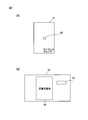
- FIG. 2 is a diagram illustrating a configuration for a user to perform an operation input in the ultrasonic image generation system of the embodiment, where (A) is a switch arrangement on the wireless probe side, and (B) is a display example on the tablet side. Indicates.
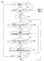
- FIG. 3 is an operation flowchart of the ultrasonic image generation system according to the embodiment.
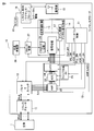
- FIG. 4 is a diagram illustrating the configuration of the ultrasonic image generation system according to the embodiment of FIG. 1 in more detail, and illustrates a block that is turned off in a measurement stop (idle) state.
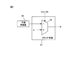
- FIG. 5 is a diagram illustrating a configuration of the clock control unit.
- FIG. 6 is a diagram illustrating a table of combinations of blocks to be powered down.
- FIG. 1 is a block diagram illustrating a configuration of an ultrasonic image generation system according to an embodiment.
- the ultrasound image generation system of the embodiment includes a wireless probe 10 and a tablet 30.
- the wireless probe 10 is held by a user of the ultrasonic image generation system, is brought into contact with the surface of the living body 1 that is a measurement target, and measures the inside of the living body 1 using ultrasonic waves.
- a widely used PC tablet is used as the tablet 30, and application software for an ultrasonic image generation system is installed and used.
- the wireless probe 10 and the tablet 30 each have a short-range wireless communication function (for example, BLUETOOTH (registered trademark)) and can wirelessly communicate with each other (wireless communication).
- the tablet 30 is not limited to a PC tablet, and a PC having a wireless communication function, a smartphone, or the like can also be used.
- the wireless probe 10 includes a transducer 11, a pulser & switch 12, an AMP & ADC 13, a digital signal processing unit 14, a (wireless probe) system control unit 18, a communication unit 19, and a switch 20.
- the digital signal processing unit 14 includes a transmission / reception control unit 15, a signal processing unit 16, and a gain control unit 17.
- the wireless probe 10 has a battery, and each part is battery-driven.
- the battery may be a primary battery or a rechargeable secondary battery.
- the transducer 11 converts the high voltage pulse signal from the pulser & switch 12 into a sound wave, outputs the sound wave to the living body 1, and converts the sound wave reflected in the living body 1 at a boundary having different acoustic impedances such as muscle and fat into an electrical signal. Convert.
- the pulser & switch 12 selects an electric signal of the reflected sound wave by the switch circuit and outputs it to the AMP & ADC 13.
- the pulser & switch circuit 12 performs a process of adjusting the focus by changing the delay amount for each channel in order to adjust the focus of a signal transmitted simultaneously in a plurality of channels in a living body.
- the AMP & ADC 13 amplifies an electric signal by an amplifier (AM), converts it to a digital signal by an ADC (Analog-to-Digital Converter), and outputs the digital signal to the digital signal processing unit 14.
- AM an electric signal
- ADC Analog-to-Digital Converter
- the pulsar & switch 12 performs pulsar transmission simultaneously for the number of ADC channels.
- the configuration of the above part is described in Patent Documents 1 and 2, etc., and is well known, and thus the description thereof is omitted.
- the transmission / reception control unit 15 controls the focusing process by the pulsar & switch circuit 12.
- the signal processing unit 16 uses the control signal from the transmission / reception control unit 15 to convert the digital signal from the AMP & ADC 13 into luminance information.
- the gain control unit 17 performs gain correction that takes into account attenuation in the living body. In the above process, 64 channels are shifted one channel at a time and transmitted and received, and an ultrasonic image can be obtained by processing the received signal.
- the communication unit 19 of the wireless probe 10 performs short-range wireless communication, receives an operation command (command) from the tablet 30 and outputs the operation command (command) to the system control unit 18, and generates an ultrasonic image generated by the digital signal processing unit 14. Data is transmitted to the tablet 30.
- the system control unit 18 controls the entire wireless probe 10 based on an operation command from the communication unit 19 and an operation signal of the switch 20.
- the switch 20 is a button switch provided in the wireless probe 10 and will be described later.
- the parts other than the system control unit 18 are turned off when the power is turned off.
- the system control unit 18 needs to detect the operation of the switch 20 for turning on the power, and is turned on even when the power is turned off. Note that the portion of the system control unit 18 that is not related to the operation of the switch 20 may be turned off when the power is turned off.
- the tablet 30 includes a (tablet) system control unit 31, a communication unit 32, and a monitor 33.
- the system control unit 31 controls the tablet.
- the communication unit 32 performs short-range wireless communication, transmits an operation command or the like to the wireless probe 10, and receives ultrasonic image data from the wireless probe 10.
- the monitor 33 is a display device having a touch screen function, displays ultrasonic image data, and detects an operation by a user input using the touch screen function.
- the monitor 33 is not limited to the one having a touch screen function, and may include a display unit, an operation switch, and the like.
- the power supply of the tablet 30 is not particularly described because the power supply capacity is sufficiently large and power consumption does not become a problem.
- the ultrasound image generation system of the embodiment includes a power-down control unit in the system control unit 18 and can perform power-down control in accordance with a switch operation.
- FIG. 2 is a diagram illustrating a configuration for a user to perform an operation input in the ultrasonic image generation system of the embodiment, where (A) is a switch arrangement on the wireless probe side, and (B) is a display example on the tablet side. Indicates.
- the wireless probe 10 has a substantially rectangular parallelepiped shape.
- the transducer 11 is provided on the lower side of FIG. 2A, the lower surface is in contact with the living body 1, and sound waves are input and output on the lower surface.
- the button switch 20 for operation is arrange
- the operation of pressing the button switch 20 for a short time when the power is on and in the image hold (measurement stop) state is determined to be an instruction to change to the state of updating the image display (during measurement), and It is determined that the operation of changing the power supply of the wireless probe 10 to OFF.
- a short press an operation of pressing the button switch 20 for a short time
- an operation of pressing the button switch 20 for a predetermined time or longer is referred to as a long press.
- a short press operation when the power is on and an image update (during measurement) state is determined to change to an image hold (measurement stop) state
- a long press operation turns off the power of the wireless probe 10. It is determined that the operation is to be changed.
- an ultrasonic image 34 and operation buttons 35 using a touch screen function are displayed on the monitor 33 of the tablet 30.
- various displays are performed, but the illustration is omitted.
- the operation button 35 is displayed as “stop”, and when touched, the ultrasonic image 34 is held (the image display update is stopped and the image at the time of touch is displayed. (Stop).
- the operation button 35 is displayed as “start”, and when touched, the update of the ultrasonic image 34 is restarted (start).
- FIG. 3 is an operation flowchart of the ultrasonic image generation system according to the embodiment. As shown in the figure, this operation flow is divided into a power-on (ON) state and a power-off (OFF) state of the wireless probe 10. This flow is shown on the assumption that the tablet 30 is in a power-on state.
- step S11 the wireless probe 10 is in a power-off state.
- step S12 it is detected whether the button switch 20 is depressed. If depression is not detected, the process returns to step S11. If depression is detected, the wireless probe 10 is turned on, and the process proceeds to step S13.
- step S13 the wireless probe 10 enters an idle state.
- the idle (stop) state is the same as the measurement stop state, which will be described later, in that the image is not updated. However, since there is no previous ultrasonic image, no ultrasonic image is displayed on the monitor 33.
- this idle (stop) state as will be described later, a part of the wireless probe 10 surrounded by a broken line marked as “power down target” in FIG. 1 is in an off state.
- step S14 it is detected whether the operation button (start) 35 is touched on the monitor 33 of the tablet 30 or the button switch 20 is pressed down. If touch and depression are not detected, the process proceeds to step S18, and if touch or depression is detected, the process proceeds to step S15.
- step S15 the wireless probe 10 is under measurement, all parts of the wireless probe 10 are turned on, and the ultrasonic image is updated in real time.
- step S16 it is detected whether the operation button (stop) 35 is touched on the monitor 33 of the tablet 30 or the button switch 20 is pressed down. If touch and depression are not detected, the process returns to step S15, and if touch or depression is detected, the process proceeds to step S17.
- step S17 the measurement is stopped, and the display is stopped with the ultrasonic image displayed on the monitor 33 when the measurement is stopped. At this time, as will be described later, a part of the portion surrounded by a broken line marked as “power down target” in FIG. 1 of the wireless probe 10 is in an OFF state.
- step S18 it is determined whether or not the button switch 20 has been pressed for a long time. If the button is pressed for a long time, the power of the wireless probe 10 is turned off and the process returns to step S11.
- the ultrasonic image generation system mainly includes the power-off state and the on-state of the wireless probe 10, and in the power-on state, the measurement stop (idle) state and the measurement-in-progress state There is a state.
- an ultrasonic image updated in real time during measurement needs to be confirmed once by setting a measurement stop. For this reason, during actual use, the two states of measurement and measurement stop are repeated. It is difficult to power down a specific block because it is necessary to constantly acquire and update an ultrasound image during measurement, but it is not necessary to acquire an ultrasound image in the measurement stop state. It becomes possible.
- Blocks that are turned off in the measurement stop state are the pulser & switch 12, the AMP & ADC 13, and the digital signal processing unit 14 in the "power down target" surrounded by a broken line in FIG.
- the system control unit 18 and the communication unit 19 are excluded from power down because it is necessary to always detect the depression of the button switch 20 and receive notification of button (start / stop) operation of the tablet 30.
- FIG. 4 is a diagram illustrating the configuration of the ultrasonic image generation system according to the embodiment of FIG. 1 in more detail, and illustrates a block that is turned off in a measurement stop (idle) state.
- a power-down control unit 21, a crystal oscillator 26, and a clock control unit 27 are further shown.
- the power-down control unit 21 and the clock control unit 27 are originally included in the system control unit 18, but are illustrated outside the system control unit 18 in FIG. 4 for ease of illustration. Further, the crystal oscillator 26 is not shown in FIG.
- the power-down control unit 21 performs power-down control based on the status information from the system control unit 18.
- the status information is information for determining whether the measurement is in progress or in the measurement stop state.
- the power down control unit 21 controls the power down state when the measurement is stopped, and cancels the power down state during the measurement.
- the crystal oscillator 26 generates and outputs a clock from which the wireless probe 10 operates.
- the clock control unit 27 controls whether the clock supply from the crystal oscillator 26 to the digital signal processing unit 14 is performed or stopped.
- the AMP & ADC 13 includes an AMP (amplifier) 22, an ADC 23, an LVDS (Low Voltage Voltage Differential) 24, and a clock generation PLL 25.
- the AMP 22 amplifies 8ch signals from the pulser & switch 12.
- the ADC 23 converts each 8ch output signal of the AMP 22 into a digital signal.
- the LVDS 24 converts the 8-channel digital signal (parallel signal) output from the AMP 22 into a low-voltage differential signal (serial signal) to be transmitted to the digital signal processing unit 14 and outputs it.
- the clock generation PLL 25 generates an operation clock used by the AMP & ADC 13 from an internal clock (for example, a clock output from the crystal oscillator 26).
- the digital signal processing unit 14 includes a clock frequency dividing unit 28 in addition to the transmission / reception control unit 15, the signal processing unit 16, and the gain control unit 17 described above.
- the clock divider 28 divides the clock output from the crystal oscillator 26 to generate an operation clock used by the digital signal processor 14.
- the power-down control unit 21 performs power-down control of the AMP (amplifier) 22, the ADC 23, the LVDS (Low Voltage-Differential Signaling) 24, the clock generation PLL 25, and the clock control unit 27.
- the digital signal processor 14 is powered down by stopping the clock supply.
- the power-down control unit 21 outputs a power-down control signal corresponding to the following control units.
- Pulsar & Switch 12 Power down by enable signal (PS_EN)
- AMP22 Power down by enable signal (AMP_EN) control
- ADC23 Power down by enable signal (ADC_EN) control
- LVDS24 Power down by enable signal (LVDS_EN)
- -PLL25 Power down by enable signal (PLL_EN)
- control-Digital signal processor 14 Power down by clock control to digital signal processor 14 with enable signal (CLK_EN).
- the clock from the crystal oscillator 26 is connected during normal operation, and the clock is masked by the clock control unit 27 during power down.
- FIG. 5 is a diagram illustrating a configuration of the clock control unit.
- the clock control unit 27 has a selector 29 that selects either the clock from the crystal oscillator or a fixed value (here, 0) in accordance with the CLK_EN signal.
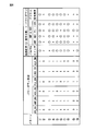
- FIG. 6 is a diagram illustrating a table of combinations of blocks to be powered down.
- Pattern 1 is a combination in which all blocks are in an operating state, and is a combination being measured.
- Pattern 2 is a pattern that can achieve the lowest power consumption by combining all the corresponding blocks in a power-down state.
- Patterns 3 to 8 describe circuit states when one of a plurality of power-down control signals is enabled (power-down control signal “0”). From this, it can be seen that the control signal and the circuit state can be controlled on a one-to-one basis.
- Pattern 9 is a combination in which only the power-down control signal PLL_EN is disabled (power-down control signal “1”) and the other five power-down control signals are enabled.
- the pattern 10 is a combination in which the pulse generator & switch 12 does not power down in addition to the clock generation PLL 25. Once the pulser & switch 12 is in the power-down state, it is necessary to register the delay amount of the transmission pulse and the output channel again, so that much time is required, so the period until the rise is long. As described above, since the relationship between the length of the rising period and the power consumption reduction degree is a trade-off, it is possible to select a combination to be powered down according to an item to be prioritized.
Landscapes
- Health & Medical Sciences (AREA)
- Life Sciences & Earth Sciences (AREA)
- Engineering & Computer Science (AREA)
- Heart & Thoracic Surgery (AREA)
- Molecular Biology (AREA)
- Biophysics (AREA)
- Nuclear Medicine, Radiotherapy & Molecular Imaging (AREA)
- Pathology (AREA)
- Radiology & Medical Imaging (AREA)
- Biomedical Technology (AREA)
- Veterinary Medicine (AREA)
- Medical Informatics (AREA)
- Physics & Mathematics (AREA)
- Surgery (AREA)
- Animal Behavior & Ethology (AREA)
- General Health & Medical Sciences (AREA)
- Public Health (AREA)
- Computer Networks & Wireless Communication (AREA)
- Computer Vision & Pattern Recognition (AREA)
- Ultra Sonic Daignosis Equipment (AREA)
Abstract
超音波信号を送受信する超音波部と、超音波部に供給する駆動信号を生成すると共に、超音波部の受信信号を処理して超音波画像信号を生成する処理を繰り返す駆動制御・信号処理部と、超音波画像信号に基づいた超音波画像の表示を繰り返し、ストップ信号入力に応じて表示画像の更新を停止し、スタート信号入力に応じて表示画像の更新を再開する表示部と、を有し、駆動制御・信号処理部は、ストップ信号入力に応じて動作の少なくとも一部を停止し、スタート信号入力に応じて停止した動作を再開する超音波画像生成システム。
Description
本発明は、超音波画像生成システムに関する。
生体に超音波を照射し、その反射を検出して生体内部の状態を示す超音波画像を生成する超音波画像生成システムが広く使用されている。一般的な超音波画像生成システムは、本体部と、本体部にケーブルで接続された超音波トランスデューサ(以下、超音波部と称す)と、を有する。本体部は、超音波部の駆動信号を生成し、生成した駆動信号をケーブルを介して超音波部に送信する。超音波部は、駆動信号にしたがって超音波を出力し、反射した超音波を捕えて反射超音波信号を生成し、本体部に送信する。本体部は、受信した反射超音波信号を処理して超音波画像を生成し、ディスプレイに表示する。
本体部は1画面分の超音波画像生成に必要な駆動信号の生成を繰り返し、それに応じて1画面分の超音波画像信号の生成が繰り返され、リアルタイムで超音波画像が表示される。観察者は、リアルタイムで変化する超音波画像を観察し、詳細に観察する場合には、画像更新の停止(ホールド)を指示する操作を行う。これに応じて、表示されている超音波画像が更新されることなく維持され、観察者は、固定された超音波画像を詳細に観察し、必要な計測等の作業を行い、さらに必要であればその超音波画像の記憶装置への記憶を指示する。超音波画像の更新が停止された状態で、超音波画像の更新開始(スタート)が指示されると、超音波画像の更新が再開される。
表示画像の更新を再開した時に即座に新しい画像に更新されることが望ましいとの操作性の観点から、超音波画像の更新が停止している間でも、駆動信号の生成および超音波画像信号の生成は繰り返されていた。
近年、超音波画像生成システムは、モバイル機器化が期待されており、小型化、低コスト化、操作性向上等が望まれている。そこで、本体部における超音波部の駆動信号生成および反射超音波信号処理に関係する部分を、超音波部に合わせて小型のプローブとし、プローブに無線通信機能を搭載して、超音波画像を表示する表示部との間を、無線通信で接続することが提案されている。これにより、プローブはワイヤレスプローブとなり、操作性が向上すると共に、表示部として表示機能を有する汎用の通信端末を使用すれば、超音波画像生成システムを低コストで実現可能である。
しかし、ワイヤレスプローブは、十分な電源供給をワイヤレスで行うのが難しいため、電池駆動が一般的となり、プローブの低消費電力化が非常に重要となる。なお、低消費電力化は、ワイヤレスプローブに限らず、前述の本体部と超音波部とを有する超音波画像生成システムにおいても有用である。
実施形態によれば、低消費電力の超音波画像生成システムが実現される。
実施形態によれば、低消費電力の超音波画像生成システムが実現される。
第1の態様の超音波画像生成システムは、超音波信号を送受信する超音波部と、駆動制御・信号処理部と、表示部と、を有する。駆動制御・信号処理部は、超音波部に供給する駆動信号を生成すると共に、超音波部の受信信号を処理して超音波画像信号を生成する処理を繰り返す。表示部は、超音波画像信号に基づいた超音波画像の表示を繰り返し、ストップ信号入力に応じて表示画像の更新を停止し、スタート信号入力に応じて表示画像の更新を再開する。駆動制御・信号処理部は、ストップ信号入力に応じて動作の少なくとも一部を停止し、スタート信号入力に応じて停止した動作を再開する。
実施形態の超音波画像生成システムは、低消費電力である。
図1は、実施形態の超音波画像生成システムの構成を示すブロック図である。
実施形態の超音波画像生成システムは、ワイヤレスプローブ10と、タブレット30と、を有する。ワイヤレスプローブ10は、超音波画像生成システムの使用者が保持し、測定対象である生体1の表面に接触され、生体1の内部を超音波により測定する。タブレット30は、広く普及しているPCタブレットが使用され、超音波画像生成システム用アプリケーションソフトをインストールして使用する。ワイヤレスプローブ10とタブレット30は、それぞれ近距離無線通信機能(例えば、BLUETOOTH(登録商標))を有し、相互に無線通信(ワイヤレス通信)可能である。タブレット30は、PCタブレットに限定されず、無線通信機能を有するPC、スマートフォン等を使用することも可能である。
実施形態の超音波画像生成システムは、ワイヤレスプローブ10と、タブレット30と、を有する。ワイヤレスプローブ10は、超音波画像生成システムの使用者が保持し、測定対象である生体1の表面に接触され、生体1の内部を超音波により測定する。タブレット30は、広く普及しているPCタブレットが使用され、超音波画像生成システム用アプリケーションソフトをインストールして使用する。ワイヤレスプローブ10とタブレット30は、それぞれ近距離無線通信機能(例えば、BLUETOOTH(登録商標))を有し、相互に無線通信(ワイヤレス通信)可能である。タブレット30は、PCタブレットに限定されず、無線通信機能を有するPC、スマートフォン等を使用することも可能である。
ワイヤレスプローブ10は、トランスデューサ11と、パルサ&スイッチ12と、AMP&ADC13と、デジタル信号処理部14と、(ワイヤレスプローブ)システム制御部18と、通信部19と、スイッチ20と、を有する。デジタル信号処理部14は、送受信制御部15と、信号処理部16と、ゲイン制御部17と、を有する。なお、図示していないが、ワイヤレスプローブ10は、電池を有し、各部は電池駆動される。電池は、一次電池でも、充電可能な二次電池でもよい。
トランスデューサ11は、パルサ&スイッチ12からの高電圧パルス信号を音波に変換し、音波を生体1に出力し、生体1内で筋肉や脂肪など音響インピーダンスが異なる境界において反射された音波を電気信号に変換する。パルサ&スイッチ12は、スイッチ回路により反射音波の電気信号を選択し、AMP&ADC13に出力する。パルサ&スイッチ回路12は、生体内で複数チャネル同時送信した信号のフォーカスを合わせる為チャネルごとに遅延量を変えてフォーカスを合わせる処理を実施する。AMP&ADC13は、アンプ(AM)により電気信号を増幅した後、ADC(Analog-to-Digital Converter)によりデジタル信号に変換し、デジタル信号処理部14に出力する。ここでは、トランスデューサ11の入出力のチャネル数が64、およびAMP&ADC13のチャネル数が8の例を示しているが、これらは任意であり、トランスデューサ11のチャネル間隔及びチャネル数により得られる超音波画像の幅及び分解能が決まる。パルサ&スイッチ12は、ADCのチャネル数分だけ同時にパルサ送信する。以上の部分の構成は、特許文献1および2等に記載されており、広く知られているので、説明は省略する。
デジタル信号処理部14では、送受信制御部15が、上記のパルサ&スイッチ回路12によるフォーカス合わせ処理を制御する。信号処理部16は、送受信制御部15からの制御信号を利用して、AMP&ADC13からのデジタル信号の輝度情報への変換を行う。また、ゲイン制御部17は、生体内での減衰を加味したゲイン補正などを実施する。以上の処理は、64チャネル分を1チャネルずつシフトして送受信し、その受信信号を処理することにより超音波画像を得ることができる。
ワイヤレスプローブ10の通信部19は、近距離無線通信を行い、タブレット30からの動作命令(コマンド)等を受信してシステム制御部18に出力すると共に、デジタル信号処理部14の生成した超音波画像データをタブレット30に送信する。システム制御部18は、通信部19からの動作命令等およびスイッチ20の操作信号に基づいて、ワイヤレスプローブ10全体の制御を行う。スイッチ20は、ワイヤレスプローブ10に設けられたボタンスイッチであり、これについては後述する。
なお、システム制御部18を除く部分は、電源オフ時にオフ状態になる。システム制御部18は、電源オンのためのスイッチ20の操作を検出する必要があり、電源オフ時にもオンしている。なお、システム制御部18内のスイッチ20の操作を検出に関係しない部分は、電源オフ時にオフしてもよい。
タブレット30は、(タブレット)システム制御部31と、通信部32と、モニタ33と、を有する。システム制御部31は、タブレットの制御を行う。通信部32は、近距離無線通信を行い、ワイヤレスプローブ10に動作命令等を送信すると共に、ワイヤレスプローブ10にから超音波画像データを受信する。モニタ33は、タッチスクリーン機能を有する表示装置で、超音波画像データを表示すると共に、タッチスクリーン機能を利用して入力される使用者による操作を検出する。なお、モニタ33は、タッチスクリーン機能を有するものに限定されず、表示部と操作スイッチ等を有するものであってもよい。なお、タブレット30の電源については電源容量が十分に大きく、電力消費が問題にならないので、特に説明しない。
実施形態の超音波画像生成システムは、上記の構成に加えて、システム制御部18にパワーダウン制御部が設けられ、スイッチ操作に応じてパワーダウン制御を行うことが可能である。
図2は、実施形態の超音波画像生成システムにおいて、使用者が操作入力を行うための構成を示す図であり、(A)がワイヤレスプローブ側のスイッチ配置、(B)がタブレット側の表示例を示す。
図2の(A)に示すように、ワイヤレスプローブ10は、略直方体の形状を有する。例えば、図2の(A)の下側にトランスデューサ11が設けられ、下面が生体1に接触され、下面で音波の入出力が行われる。操作用のボタンスイッチ20が、側面に配置される。使用者は、ボタンスイッチ20に指を掛けてワイヤレスプローブ10の側面を把持し、下面を生体1に接触され、ボタンスイッチ20を操作する。ワイヤレスプローブ10の電源がオフの状態でボタンスイッチ20を押し下げる操作は、ワイヤレスプローブ10の電源をオンにする操作と判定される。電源がオンの状態で且つ画像ホールド(測定ストップ)状態の時にボタンスイッチ20を短時間押し下げる操作は、画像表示を更新する(測定中)状態に変化する指示と判定され、所定時間以上押し下げる操作は、ワイヤレスプローブ10の電源をオフに変化させる操作と判定される。以下、ボタンスイッチ20を短時間押し下げる操作を短押し、所定時間以上押し下げる操作を長押しと称する。さらに、電源がオンの状態で且つ画像更新(測定中)状態の時の短押し操作は、画像ホールド(測定ストップ)状態に変化させる操作と判定され、長押し操作はワイヤレスプローブ10の電源をオフに変化させる操作と判定される。
図2の(B)に示すように、タブレット30のモニタ33には、超音波画像34およびタッチスクリーン機能による操作ボタン35が表示され。超音波画像34および操作ボタン35の他にも各種の表示が行われるが、図示を省略している。超音波画像34がリアルタイムで更新されている時に、操作ボタン35は「ストップ」と表示され、それにタッチすると超音波画像34がホールドされる(画像表示の更新を停止し、タッチ時の画像が表示され続ける)(ストップ)。また、超音波画像34がホールドしている(測定ストップ)時に、操作ボタン35は「スタート」と表示され、それにタッチすると超音波画像34の更新が再開される(スタート)。
図3は、実施形態の超音波画像生成システムの動作フロー図である。
図示のように、この動作フローは、ワイヤレスプローブ10が電源オン(ON)状態と、電源オフ(OFF)状態とに分けられる。なお、このフローは、タブレット30が電源オン状態であるとして示している。
図示のように、この動作フローは、ワイヤレスプローブ10が電源オン(ON)状態と、電源オフ(OFF)状態とに分けられる。なお、このフローは、タブレット30が電源オン状態であるとして示している。
ステップS11で、ワイヤレスプローブ10は電源オフ状態である。
ステップS12で、ボタンスイッチ20が押し下げられたか検出し、押し下げを検出できなければステップS11に戻り、押し下げを検出したらワイヤレスプローブ10を電源オン状態にし、ステップS13に進む。
ステップS12で、ボタンスイッチ20が押し下げられたか検出し、押し下げを検出できなければステップS11に戻り、押し下げを検出したらワイヤレスプローブ10を電源オン状態にし、ステップS13に進む。
ステップS13で、ワイヤレスプローブ10は、アイドル状態になる。アイドル(ストップ)状態は、後述する測定ストップ状態と画像の更新が行われない点で同じであるが、直前の超音波画像が存在しないため、モニタ33には超音波画像は表示されない。このアイドル(ストップ)状態では、後述するように、ワイヤレスプローブ10の図1で「パワーダウン対象」と記した破線で囲んだ部分の一部がオフ状態である。
ステップS14で、タブレット30のモニタ33において操作ボタン(スタート)35にタッチされたか、またはボタンスイッチ20が押し下げられたかを検出する。タッチおよび押し下げを検出しなければステップS18に進み、タッチまたは押し下げを検出すればステップS15に進む。
ステップS15で、ワイヤレスプローブ10は、測定中となり、ワイヤレスプローブ10のすべての部分がオン状態になり、リアルタイムで超音波画像が更新される。
ステップS16で、タブレット30のモニタ33において操作ボタン(ストップ)35にタッチされたか、またはボタンスイッチ20が押し下げられたかを検出する。タッチおよび押し下げを検出しなければステップS15に戻り、タッチまたは押し下げを検出すればステップS17に進む。
ステップS16で、タブレット30のモニタ33において操作ボタン(ストップ)35にタッチされたか、またはボタンスイッチ20が押し下げられたかを検出する。タッチおよび押し下げを検出しなければステップS15に戻り、タッチまたは押し下げを検出すればステップS17に進む。
ステップS17で、測定ストップ状態になり、ストップした時のモニタ33に表示された超音波画像で表示を停止する。この時、後述するように、ワイヤレスプローブ10の図1で「パワーダウン対象」と記した破線で囲んだ部分の一部がオフ状態である。
ステップS18で、ボタンスイッチ20が長押しされたか判定し、長押しであればワイヤレスプローブ10の電源をオフしてステップS11に戻り、長押しでなければステップS14に戻る。
ステップS18で、ボタンスイッチ20が長押しされたか判定し、長押しであればワイヤレスプローブ10の電源をオフしてステップS11に戻り、長押しでなければステップS14に戻る。
以上説明したように、実施形態の超音波画像生成システムは、大きくはワイヤレスプローブ10の電源オフ状態とオン状態があり、電源オン状態では、測定ストップ(アイドル)状態と、測定中状態の2つの状態がある。前述のように、超音波測定においては、測定中にリアルタイムに更新されている超音波画像を、測定ストップとすることで一度画像を確定させる必要がある。そのため、実際の使用時には、測定中と測定ストップの2つの状態が繰り返される。測定中は常に超音波画像を取得して更新する必要があるため特定のブロックをパワーダウンすることは難しいが、測定ストップ状態では超音波画像を取得する必要が無いため、各ブロックのパワーダウンが可能となる。
次に、ワイヤレスプローブ10において、測定ストップ(アイドル)状態でオフする部分について説明する。
測定ストップ状態でオフするブロックは、図1において破線で囲った「パワーダウン対象」内の、パルサ&スイッチ12、AMP&ADC13、デジタル信号処理部14である。システム制御部18および通信部19は、ボタンスイッチ20の押し下げ検出およびタブレット30のボタン(スタート、ストップ)操作の通知の受信を常に行う必要があるのでパワーダウンの対象外としている。
測定ストップ状態でオフするブロックは、図1において破線で囲った「パワーダウン対象」内の、パルサ&スイッチ12、AMP&ADC13、デジタル信号処理部14である。システム制御部18および通信部19は、ボタンスイッチ20の押し下げ検出およびタブレット30のボタン(スタート、ストップ)操作の通知の受信を常に行う必要があるのでパワーダウンの対象外としている。
図4は、図1の実施形態の超音波画像生成システムの構成をより詳細に示すと共に、測定ストップ(アイドル)状態でオフするブロックを説明する図である。
図4では、パワーダウン制御部21、水晶発振器26およびクロック制御部27がさらに示される。パワーダウン制御部21およびクロック制御部27は、本来システム制御部18に含まれる部分であるが、図示を容易にするために、図4ではシステム制御部18の外部に示している。また、水晶発振器26は、図1では図示を省略していた。
図4では、パワーダウン制御部21、水晶発振器26およびクロック制御部27がさらに示される。パワーダウン制御部21およびクロック制御部27は、本来システム制御部18に含まれる部分であるが、図示を容易にするために、図4ではシステム制御部18の外部に示している。また、水晶発振器26は、図1では図示を省略していた。
パワーダウン制御部21は、システム制御部18からのステータス情報を元にパワーダウン制御を行う。ステータス情報は、測定中か測定ストップ状態かを判別するための情報で、パワーダウン制御部21は、測定ストップ時にパワーダウン状態に制御し、測定中はパワーダウン状態を解除する。
水晶発振器26は、ワイヤレスプローブ10がクロック動作する元になるクロックを生成して出力する。クロック制御部27は、水晶発振器26からデジタル信号処理部14でのクロック供給を行うか停止するかを制御する。
図示のように、AMP&ADC13は、AMP(増幅器)22と、ADC23と、LVDS(Low Voltage Differential Signaling)24と、クロック生成PLL25と、を有する。AMP22は、パルサ&スイッチ12からの8chの信号をそれぞれ増幅する。ADC23は、AMP22の8chの出力信号をそれぞれデジタル信号に変換する。LVDS24は、AMP22の出力する8chのデジタル信号(パラレル信号)を、デジタル信号処理部14に送信するための低電圧差動信号(シリアル信号)に変換して出力する。クロック生成PLL25は、内部クロック(例えば水晶発振器26の出力するクロック)から、AMP&ADC13で使用する動作クロックを生成する。
デジタル信号処理部14は、前述の送受信制御部15、信号処理部16およびゲイン制御部17に加えて、クロック分周部28を有する。クロック分周部28は、水晶発振器26の出力するクロックを分周して、デジタル信号処理部14で使用する動作クロックを生成する。
パワーダウン制御部21は、AMP(増幅器)22、ADC23、LVDS(Low Voltage Differential Signaling)24、クロック生成PLL25およびクロック制御部27のパワーダウン制御を行う。またデジタル信号処理部14においては、クロック供給を停止することでパワーダウンしている。
パワーダウン制御部21は、図4に示すように、以下の制御単位に対応してパワーダウン制御信号を出力する。
・パルサ&スイッチ12:イネーブル信号(PS_EN)によるパワーダウン
・AMP22:イネーブル信号(AMP_EN)制御によるパワーダウン
・ADC23:イネーブル信号(ADC_EN)制御によるパワーダウン
・LVDS24:イネーブル信号(LVDS_EN)制御によるパワーダウン
・PLL25:イネーブル信号(PLL_EN)制御によるパワーダウン
・デジタル信号処理部14:イネーブル信号(CLK_EN)で、デジタル信号処理部14へのクロック制御によるパワーダウン。通常時は水晶発振器26からのクロックを接続し、パワーダウン時はクロック制御部27でクロックをマスクする
・パルサ&スイッチ12:イネーブル信号(PS_EN)によるパワーダウン
・AMP22:イネーブル信号(AMP_EN)制御によるパワーダウン
・ADC23:イネーブル信号(ADC_EN)制御によるパワーダウン
・LVDS24:イネーブル信号(LVDS_EN)制御によるパワーダウン
・PLL25:イネーブル信号(PLL_EN)制御によるパワーダウン
・デジタル信号処理部14:イネーブル信号(CLK_EN)で、デジタル信号処理部14へのクロック制御によるパワーダウン。通常時は水晶発振器26からのクロックを接続し、パワーダウン時はクロック制御部27でクロックをマスクする
図5は、クロック制御部の構成を示す図である。
クロック制御部27は、CLK_EN信号に応じて、水晶発振器からのクロックと固定値(ここでは0)のいずれかを選択するセレクタ29を有する。
クロック制御部27は、CLK_EN信号に応じて、水晶発振器からのクロックと固定値(ここでは0)のいずれかを選択するセレクタ29を有する。
以上の通り、どのブロックをパワーダウンするかは任意に選択可能であり、消費電力だけでは無く、パワーダウン状態から動作状態への復帰時間も考慮して選択することが望ましい。
図6は、パワーダウンするブロックの組み合わせ例の表を示す図である。
パターン1は、全ブロックが動作状態となる組合せであり、測定中の組み合わせである。
パターン2は、該当する全ブロックをパワーダウン状態にする組合せで、もっとも低消費電力を実現できるパターンである。
パターン3から8は、複数のパワーダウン制御信号の一つを有効(パワーダウン制御信号“0”)にした際の回路状態を記載している。ここから制御信号と回路状態は1対1で制御できることが分かる。
パターン9は、パワーダウン制御信号PLL_ENのみを無効(パワーダウン制御信号“1”)にし、他の5つのパワーダウン制御信号を有効にした組合せである。PLL_ENで制御するクロック生成PLL25は、PLL_EN=0から1にした後に、回路が安定して動作クロックを出力するまでの安定待ち期間が必要であり、この立ち上がりまでの期間が問題になる場合は、このブロックのみパワーダウンしないことが望ましい。
パターン10は、クロック生成PLL25に加えてパルサ&スイッチ12もパワーダウンをしない組合せである。パルサ&スイッチ12は、一度パワーダウン状態にすると送信パルスの遅延量や出力チャネルを再度レジスタ設定する必要があるためその分の時間が必要になるため、立ち上りまでの期間が長くなる。
以上の通り、立ち上り期間の長さと消費電力低減具合との関係はトレードオフになるため、優先すべき項目に応じてパワーダウンする組み合わせを選択できるようにしておく。
パターン1は、全ブロックが動作状態となる組合せであり、測定中の組み合わせである。
パターン2は、該当する全ブロックをパワーダウン状態にする組合せで、もっとも低消費電力を実現できるパターンである。
パターン3から8は、複数のパワーダウン制御信号の一つを有効(パワーダウン制御信号“0”)にした際の回路状態を記載している。ここから制御信号と回路状態は1対1で制御できることが分かる。
パターン9は、パワーダウン制御信号PLL_ENのみを無効(パワーダウン制御信号“1”)にし、他の5つのパワーダウン制御信号を有効にした組合せである。PLL_ENで制御するクロック生成PLL25は、PLL_EN=0から1にした後に、回路が安定して動作クロックを出力するまでの安定待ち期間が必要であり、この立ち上がりまでの期間が問題になる場合は、このブロックのみパワーダウンしないことが望ましい。
パターン10は、クロック生成PLL25に加えてパルサ&スイッチ12もパワーダウンをしない組合せである。パルサ&スイッチ12は、一度パワーダウン状態にすると送信パルスの遅延量や出力チャネルを再度レジスタ設定する必要があるためその分の時間が必要になるため、立ち上りまでの期間が長くなる。
以上の通り、立ち上り期間の長さと消費電力低減具合との関係はトレードオフになるため、優先すべき項目に応じてパワーダウンする組み合わせを選択できるようにしておく。
以上、実施形態を説明したが、ここに記載したすべての例や条件は、発明および技術に適用する発明の概念の理解を助ける目的で記載されたものである。特に記載された例や条件は発明の範囲を制限することを意図するものではなく、明細書のそのような例の構成は発明の利点および欠点を示すものではない。発明の実施形態を詳細に記載したが、各種の変更、置き換え、変形が発明の精神および範囲を逸脱することなく行えることが理解されるべきである。
10 ワイヤレスプローブ
11 トランスデューサ
12 パルサ&スイッチ
13 AMP&ADC
14 デジタル信号処理部
15 送受信制御部
16 信号処理部
17 ゲイン制御部
18 (ワイヤレスプローブ)システム制御部
19 通信部
20 スイッチ
21 パワーダウン制御部
22 アンプ
23 ADC
24 LVDS
25 クロック生成PLL
26 水晶発振器
27 クロック制御部
28 クロック分周部
11 トランスデューサ
12 パルサ&スイッチ
13 AMP&ADC
14 デジタル信号処理部
15 送受信制御部
16 信号処理部
17 ゲイン制御部
18 (ワイヤレスプローブ)システム制御部
19 通信部
20 スイッチ
21 パワーダウン制御部
22 アンプ
23 ADC
24 LVDS
25 クロック生成PLL
26 水晶発振器
27 クロック制御部
28 クロック分周部
Claims (4)
- 超音波信号を送受信する超音波部と、
前記超音波部に供給する駆動信号を生成すると共に、前記超音波部の受信信号を処理して超音波画像信号を生成する処理を繰り返す駆動制御・信号処理部と、
前記超音波画像信号に基づいた超音波画像の表示を繰り返し、ストップ信号入力に応じて表示画像の更新を停止し、スタート信号入力に応じて表示画像の更新を再開する表示部と、を有し、
前記駆動制御・信号処理部は、前記ストップ信号入力に応じて動作の少なくとも一部を停止し、前記スタート信号入力に応じて停止した動作を再開することを特徴とする超音波画像生成システム。 - 前記超音波部および前記駆動制御・信号処理部を含むプローブ部と、
前記表示部を含み、前記プローブ部から独立したタブレット部と、を有し、
前記プローブ部および前記タブレット部は、相互に無線通信するための通信部をそれぞれ有し、
前記プローブ部は、電池駆動される請求項1に記載の超音波画像生成システム。 - 前記ストップ信号入力は、前記プローブ部に設けられたスイッチの操作、または前記タブレット部のタッチスクリーン操作による入力であり、
前記ストップ信号入力を検出した前記プローブ部および前記タブレット部の一方は、他方に前記通信部を介して前記ストップ信号入力を通知する請求項2に記載の超音波画像生成システム。 - 前記プローブ部は、前記スイッチが所定時間以上操作された時に、電源オフ状態になる請求項3に記載の超音波画像生成システム。
Priority Applications (3)
| Application Number | Priority Date | Filing Date | Title |
|---|---|---|---|
| CN201680039920.1A CN107847221B (zh) | 2015-07-09 | 2016-02-29 | 超声波图像生成系统 |
| DE112016003109.2T DE112016003109T5 (de) | 2015-07-09 | 2016-02-29 | Ultraschallbild-Erzeugungssysteme |
| US15/860,086 US20180116636A1 (en) | 2015-07-09 | 2018-01-02 | Ultrasonic image generation system |
Applications Claiming Priority (2)
| Application Number | Priority Date | Filing Date | Title |
|---|---|---|---|
| JP2015-138059 | 2015-07-09 | ||
| JP2015138059A JP6507896B2 (ja) | 2015-07-09 | 2015-07-09 | 超音波画像生成システム |
Related Child Applications (1)
| Application Number | Title | Priority Date | Filing Date |
|---|---|---|---|
| US15/860,086 Continuation US20180116636A1 (en) | 2015-07-09 | 2018-01-02 | Ultrasonic image generation system |
Publications (1)
| Publication Number | Publication Date |
|---|---|
| WO2017006578A1 true WO2017006578A1 (ja) | 2017-01-12 |
Family
ID=57685309
Family Applications (1)
| Application Number | Title | Priority Date | Filing Date |
|---|---|---|---|
| PCT/JP2016/056093 Ceased WO2017006578A1 (ja) | 2015-07-09 | 2016-02-29 | 超音波画像生成システム |
Country Status (5)
| Country | Link |
|---|---|
| US (1) | US20180116636A1 (ja) |
| JP (1) | JP6507896B2 (ja) |
| CN (1) | CN107847221B (ja) |
| DE (1) | DE112016003109T5 (ja) |
| WO (1) | WO2017006578A1 (ja) |
Cited By (2)
| Publication number | Priority date | Publication date | Assignee | Title |
|---|---|---|---|---|
| CN111565644A (zh) * | 2018-01-11 | 2020-08-21 | 株式会社索思未来 | 超声波诊断装置以及超声波诊断系统 |
| JP7505577B2 (ja) | 2020-11-16 | 2024-06-25 | 株式会社ソシオネクスト | 超音波装置および超音波装置の制御方法 |
Families Citing this family (6)
| Publication number | Priority date | Publication date | Assignee | Title |
|---|---|---|---|---|
| JP7082193B2 (ja) * | 2018-05-18 | 2022-06-07 | 富士フイルム株式会社 | 超音波診断装置および超音波診断装置の制御方法 |
| JP7267054B2 (ja) * | 2019-03-25 | 2023-05-01 | 三菱重工業株式会社 | パルサレシーバ |
| JP7278124B2 (ja) * | 2019-03-25 | 2023-05-19 | 三菱重工業株式会社 | パルサレシーバ |
| WO2021049148A1 (ja) * | 2019-09-13 | 2021-03-18 | 富士フイルム株式会社 | 超音波システムおよび超音波システムの制御方法 |
| CN121101625A (zh) * | 2019-11-06 | 2025-12-12 | 艾普凌科有限公司 | 超声波诊断系统、程序产品、超声波诊断方法 |
| JP2023062481A (ja) * | 2021-10-21 | 2023-05-08 | ニプロ株式会社 | 超音波診断装置 |
Citations (3)
| Publication number | Priority date | Publication date | Assignee | Title |
|---|---|---|---|---|
| JP2007282957A (ja) * | 2006-04-19 | 2007-11-01 | Aloka Co Ltd | ワイヤレス超音波診断装置 |
| JP2012245036A (ja) * | 2011-05-25 | 2012-12-13 | Konica Minolta Medical & Graphic Inc | 超音波探触子 |
| JP2012249984A (ja) * | 2011-06-07 | 2012-12-20 | Konica Minolta Medical & Graphic Inc | 超音波探触子 |
Family Cites Families (8)
| Publication number | Priority date | Publication date | Assignee | Title |
|---|---|---|---|---|
| JP3221676B2 (ja) * | 1990-08-08 | 2001-10-22 | 株式会社日立メディコ | 超音波診断装置 |
| US20020173721A1 (en) * | 1999-08-20 | 2002-11-21 | Novasonics, Inc. | User interface for handheld imaging devices |
| JP2009124896A (ja) * | 2007-11-16 | 2009-06-04 | Oki Semiconductor Co Ltd | 電子機器、遠隔操作装置、及び遠隔操作システム |
| CN101601594B (zh) * | 2009-07-08 | 2012-01-18 | 汕头市超声仪器研究所有限公司 | 一种医用b超前端激励方法 |
| JP5443309B2 (ja) * | 2010-09-10 | 2014-03-19 | 富士フイルム株式会社 | 超音波診断装置および方法 |
| JP5647957B2 (ja) * | 2010-09-10 | 2015-01-07 | 富士フイルム株式会社 | 超音波診断装置 |
| JP5831000B2 (ja) * | 2011-07-21 | 2015-12-09 | ソニー株式会社 | 信号処理装置、制御方法、並びに信号処理システムおよび方法 |
| US9757651B2 (en) * | 2013-09-05 | 2017-09-12 | Samsung Electronics Co., Ltd. | Electronic device and method of processing user input by electronic device |
-
2015
- 2015-07-09 JP JP2015138059A patent/JP6507896B2/ja active Active
-
2016
- 2016-02-29 CN CN201680039920.1A patent/CN107847221B/zh active Active
- 2016-02-29 DE DE112016003109.2T patent/DE112016003109T5/de active Pending
- 2016-02-29 WO PCT/JP2016/056093 patent/WO2017006578A1/ja not_active Ceased
-
2018
- 2018-01-02 US US15/860,086 patent/US20180116636A1/en not_active Abandoned
Patent Citations (3)
| Publication number | Priority date | Publication date | Assignee | Title |
|---|---|---|---|---|
| JP2007282957A (ja) * | 2006-04-19 | 2007-11-01 | Aloka Co Ltd | ワイヤレス超音波診断装置 |
| JP2012245036A (ja) * | 2011-05-25 | 2012-12-13 | Konica Minolta Medical & Graphic Inc | 超音波探触子 |
| JP2012249984A (ja) * | 2011-06-07 | 2012-12-20 | Konica Minolta Medical & Graphic Inc | 超音波探触子 |
Cited By (3)
| Publication number | Priority date | Publication date | Assignee | Title |
|---|---|---|---|---|
| CN111565644A (zh) * | 2018-01-11 | 2020-08-21 | 株式会社索思未来 | 超声波诊断装置以及超声波诊断系统 |
| CN111565644B (zh) * | 2018-01-11 | 2023-08-29 | 株式会社索思未来 | 超声波诊断装置以及超声波诊断系统 |
| JP7505577B2 (ja) | 2020-11-16 | 2024-06-25 | 株式会社ソシオネクスト | 超音波装置および超音波装置の制御方法 |
Also Published As
| Publication number | Publication date |
|---|---|
| CN107847221B (zh) | 2021-01-08 |
| CN107847221A (zh) | 2018-03-27 |
| US20180116636A1 (en) | 2018-05-03 |
| JP2017018276A (ja) | 2017-01-26 |
| DE112016003109T5 (de) | 2018-04-12 |
| JP6507896B2 (ja) | 2019-05-08 |
Similar Documents
| Publication | Publication Date | Title |
|---|---|---|
| JP6507896B2 (ja) | 超音波画像生成システム | |
| KR102223164B1 (ko) | 무선 프로브 및 그에 따른 무선 프로브의 전원 제어 방법 | |
| WO2013108461A1 (ja) | 医療システム | |
| JP2018519964A5 (ja) | ||
| US20240315668A1 (en) | Ultrasound diagnostic apparatus and control method of ultrasound diagnostic apparatus | |
| JP2005253776A (ja) | 超音波診断装置 | |
| US12366887B2 (en) | Systems and methods for wireless charger docking | |
| CN110267142B (zh) | 一种移动终端及控制方法 | |
| US10292591B2 (en) | Electronic device for adjusting power to an earphone transmitter | |
| US20180125458A1 (en) | Ultrasonic image generation system and ultrasonic wireless probe | |
| KR20140085278A (ko) | 호스트 장치, 디스플레이 장치, 호스트 장치의 제어 방법 및 디스플레이 장치의 제어 방법 | |
| JP5934816B1 (ja) | 超音波診断システム | |
| JP5711647B2 (ja) | 超音波診断装置および超音波画像生成方法 | |
| JP2017099785A (ja) | 超音波診断システム | |
| TWI579735B (zh) | 鍵盤控制電路 | |
| JP6911578B2 (ja) | 電子機器 | |
| JP4704022B2 (ja) | 超音波診断装置 | |
| KR20190109086A (ko) | 센서기반으로 사운드를 발생시키는 악기 연주음 검출장치 | |
| KR102264756B1 (ko) | 무선 프로브 및 그에 따른 무선 프로브의 전원 제어 방법 | |
| JP7784818B2 (ja) | 超音波プローブ | |
| JP2010206914A (ja) | 電気機器の電源制御システム | |
| JP2017072943A (ja) | 検出装置及び検出プログラム | |
| CN120131058A (zh) | 控制功耗的方法、电子设备及存储介质 | |
| CN114668970A (zh) | 按摩设备控制方法、电极式按摩设备及计算机存储介质 | |
| JP2015039077A (ja) | 通信装置、及び通信方法 |
Legal Events
| Date | Code | Title | Description |
|---|---|---|---|
| 121 | Ep: the epo has been informed by wipo that ep was designated in this application |
Ref document number: 16821049 Country of ref document: EP Kind code of ref document: A1 |
|
| WWE | Wipo information: entry into national phase |
Ref document number: 112016003109 Country of ref document: DE |
|
| 122 | Ep: pct application non-entry in european phase |
Ref document number: 16821049 Country of ref document: EP Kind code of ref document: A1 |