WO2017006507A1 - 噴射制御装置 - Google Patents
噴射制御装置 Download PDFInfo
- Publication number
- WO2017006507A1 WO2017006507A1 PCT/JP2016/002543 JP2016002543W WO2017006507A1 WO 2017006507 A1 WO2017006507 A1 WO 2017006507A1 JP 2016002543 W JP2016002543 W JP 2016002543W WO 2017006507 A1 WO2017006507 A1 WO 2017006507A1
- Authority
- WO
- WIPO (PCT)
- Prior art keywords
- injection
- injection amount
- fuel
- control device
- valve
- Prior art date
- Legal status (The legal status is an assumption and is not a legal conclusion. Google has not performed a legal analysis and makes no representation as to the accuracy of the status listed.)
- Ceased
Links
Images






Classifications
-
- F—MECHANICAL ENGINEERING; LIGHTING; HEATING; WEAPONS; BLASTING
- F02—COMBUSTION ENGINES; HOT-GAS OR COMBUSTION-PRODUCT ENGINE PLANTS
- F02D—CONTROLLING COMBUSTION ENGINES
- F02D41/00—Electrical control of supply of combustible mixture or its constituents
- F02D41/02—Circuit arrangements for generating control signals
- F02D41/04—Introducing corrections for particular operating conditions
-
- F—MECHANICAL ENGINEERING; LIGHTING; HEATING; WEAPONS; BLASTING
- F02—COMBUSTION ENGINES; HOT-GAS OR COMBUSTION-PRODUCT ENGINE PLANTS
- F02D—CONTROLLING COMBUSTION ENGINES
- F02D41/00—Electrical control of supply of combustible mixture or its constituents
- F02D41/20—Output circuits, e.g. for controlling currents in command coils
-
- F—MECHANICAL ENGINEERING; LIGHTING; HEATING; WEAPONS; BLASTING
- F02—COMBUSTION ENGINES; HOT-GAS OR COMBUSTION-PRODUCT ENGINE PLANTS
- F02D—CONTROLLING COMBUSTION ENGINES
- F02D45/00—Electrical control not provided for in groups F02D41/00 - F02D43/00
-
- F—MECHANICAL ENGINEERING; LIGHTING; HEATING; WEAPONS; BLASTING
- F02—COMBUSTION ENGINES; HOT-GAS OR COMBUSTION-PRODUCT ENGINE PLANTS
- F02M—SUPPLYING COMBUSTION ENGINES IN GENERAL WITH COMBUSTIBLE MIXTURES OR CONSTITUENTS THEREOF
- F02M51/00—Fuel-injection apparatus characterised by being operated electrically
-
- F—MECHANICAL ENGINEERING; LIGHTING; HEATING; WEAPONS; BLASTING
- F02—COMBUSTION ENGINES; HOT-GAS OR COMBUSTION-PRODUCT ENGINE PLANTS
- F02M—SUPPLYING COMBUSTION ENGINES IN GENERAL WITH COMBUSTIBLE MIXTURES OR CONSTITUENTS THEREOF
- F02M51/00—Fuel-injection apparatus characterised by being operated electrically
- F02M51/06—Injectors peculiar thereto with means directly operating the valve needle
-
- F—MECHANICAL ENGINEERING; LIGHTING; HEATING; WEAPONS; BLASTING
- F02—COMBUSTION ENGINES; HOT-GAS OR COMBUSTION-PRODUCT ENGINE PLANTS
- F02M—SUPPLYING COMBUSTION ENGINES IN GENERAL WITH COMBUSTIBLE MIXTURES OR CONSTITUENTS THEREOF
- F02M59/00—Pumps specially adapted for fuel-injection and not provided for in groups F02M39/00 -F02M57/00, e.g. rotary cylinder-block type of pumps
- F02M59/20—Varying fuel delivery in quantity or timing
Definitions
- the present disclosure relates to an injection control device that controls the operation of a fuel injection valve in an internal combustion engine.
- a fuel injection valve that injects fuel in an internal combustion engine changes the opening of an injection port by the movement of a valve body provided therein, whereby the fuel injection rate (the amount of fuel injected per unit time) Is something that changes.
- An actuator for moving the valve body is provided inside the fuel injection valve.
- the injection control device adjusts the position of the valve body, that is, the opening degree of the injection port by controlling the operation of the actuator, and makes the fuel injection amount from the fuel injection valve coincide with the target injection amount.
- a piezoelectric actuator is used as an actuator. As the drive voltage applied to the piezoelectric actuator increases, the valve element moves to the valve opening side (the side opposite to the injection port). After the valve body reaches the position on the most valve opening side in the moving range, the fuel injection amount is adjusted by adjusting the time during which the valve is open.
- the valve body When the fuel injection amount is relatively large, the valve body returns to the (maximum) valve opening position after the valve body rebounds as described above, and therefore the influence of the rebound on the fuel injection amount is small. However, when the fuel injection amount is relatively small, the fuel injection ends before the bounced valve body returns to the original position, so the influence of the rebound on the fuel injection amount becomes large. .
- An object of the present disclosure is to provide an injection control device that can suppress a deviation between an actual injection amount and a target injection amount even when the fuel injection amount is very small.
- An injection control device is an injection control device that controls the operation of a fuel injection valve that injects fuel provided in an internal combustion engine, and a target injection amount that is a target value of the fuel injection amount;
- a comparison unit that compares a predetermined threshold injection amount, and a valve body that controls the actuator of the fuel injection valve by the drive voltage to change the fuel injection rate and changes the opening of the injection port of the fuel injection valve
- a control unit that moves the valve body to a maximum injection position at which the injection rate is maximized when the comparison unit determines that the target injection amount is greater than the threshold injection amount.
- the valve body When the control unit determines that the target injection amount is equal to or less than the threshold injection amount, the valve body is preset as a position where the opening is smaller than the maximum injection position. Operates within the range that does not exceed the suppression injection position. As to, performing a restriction mode for restricting the operation of the actuator.
- the operation of the valve body is limited. Specifically, the operation of the actuator is limited so that the valve element operates within a range that does not exceed a preset suppression injection position. Since the position of the valve body at the time of fuel injection is limited to be within the range from the valve closing position to the suppression injection position, a phenomenon that the valve body reaches the position closest to the valve opening side and rebounds may occur. It is suppressed. As a result, a phenomenon in which the fuel injection amount is reduced due to the influence of rebound is less likely to occur, and a deviation between the actual injection amount and the target injection amount is suppressed.
- FIG. 1 is a diagram schematically illustrating a configuration of an injection control device according to an embodiment of the present disclosure and a fuel injection valve to be controlled.
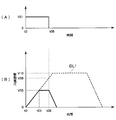
- FIG. 2 is a diagram illustrating an example of a rectangular wave input as an injection command value and a change in drive voltage applied to the piezoelectric actuator.
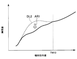
- FIG. 3 is a diagram showing the relationship between the injection command value and the injection amount
- FIG. 4 is a diagram illustrating examples of waveforms of actual drive voltages corresponding to various injection command values.
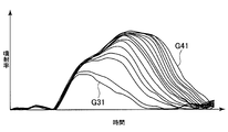
- FIG. 5 is a diagram showing a change in the actual fuel injection rate when the drive voltage shown in FIG. 4 is input.
- FIG. 1 is a diagram schematically illustrating a configuration of an injection control device according to an embodiment of the present disclosure and a fuel injection valve to be controlled.
- FIG. 2 is a diagram illustrating an example of a rectangular wave input as an injection command value and a change in drive voltage applied to the piezoelectric actuator.
- FIG. 3 is a diagram showing the relationship between the injection command value
- FIG. 6 is a flowchart showing a flow of processing executed by the injection control device of FIG.
- FIG. 7 is a diagram illustrating an example of a rectangular wave input as an injection command value and a change in drive voltage applied to the piezoelectric actuator when conventional control is performed
- FIG. 8 is a diagram illustrating an example of a rectangular wave input as an injection command value and a change in drive voltage applied to the piezoelectric actuator when conventional control is performed
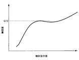
- FIG. 9 is a diagram illustrating a relationship between an injection command value and an injection amount when conventional control is performed.
- FIG. 10 is a diagram illustrating examples of waveforms of actual drive voltages corresponding to various injection command values when conventional control is performed
- FIG. 11 is a diagram showing a change in the actual fuel injection rate when the drive voltage shown in FIG. 10 is input.
- an injection control device 20 according to an embodiment of the present disclosure and a fuel injection valve 10 that is a control target of the injection control device 20 will be described. First, a specific structure of the fuel injection valve 10 will be described.
- the fuel injection valve 10 is for injecting fuel into an internal combustion engine (not shown) of a vehicle, and is also called a so-called injector.
- the fuel injection valve 10 includes a housing 100, a cap 200, a nozzle body 300, a needle 400, a piezoelectric actuator 500, and a piston 600.
- the housing 100 is a portion formed as a substantially cylindrical container.
- a piezoelectric actuator 500 and a piston 600 are housed inside the housing 100.
- a fuel supply pipe 110 is connected to the side surface of the housing 100.
- the fuel supply pipe 110 is a pipe for supplying fuel from a fuel pump (not shown) to the fuel injection valve 10. The fuel fed from the fuel pump flows into the housing 100 through the fuel supply pipe 110 and is then injected from an injection port 310 formed at the tip of the nozzle body 300.
- the internal space of the housing 100 is partitioned by a partition plate 120.
- a part of the piezoelectric actuator 500 and the piston 600 is accommodated in a space above the partition plate 120 (on the side opposite to the nozzle body 300).
- Another part of the piston 600 is housed in a space below the partition plate 120 (on the nozzle body 300 side).
- the fuel supplied to the fuel injection valve 10 through the fuel supply pipe 110 flows only into the space below the partition plate 120 and does not flow into the space where the piezoelectric actuator 500 is disposed.
- a flow path 130 is formed below the partition plate 120 in the housing 100.
- the flow path 130 has a first end (upper end) connected to the inside of the fuel supply pipe 110 and a second end (lower end) that extends to the lower end of the housing 100.
- the cap 200 is a lid-like member, and is arranged so as to cover one end side (the lower end side in FIG. 1) of the housing 100.
- the inner peripheral surface of the cap 200 is subjected to female screw processing, and the outer peripheral surface of the housing 100 is subjected to male screw processing.
- the cap 200 is fixed in a state where it is screwed into the housing 100.
- a through hole 201 for inserting the nozzle body 300 is formed in the cap 200.
- a substantially disc-shaped partition plate 210 is disposed between the housing 100 and the nozzle body 300 in a state of being sandwiched between the two.
- the lower end of the housing 100 is in contact with the upper surface 211 of the partition plate 210.
- the upper end of the nozzle body 300 is in contact with the lower surface 212 of the partition plate 210.
- Two through holes 213 and 214 are formed in the partition plate 210 so as to penetrate from the upper surface 211 to the lower surface 212.
- the upper end of the through hole 213 is opened at a position facing the lower end of the flow path 130. Further, the lower end of the through hole 213 is opened at a position substantially coincident with the central axis of the nozzle body 300. Through the through hole 213, the flow path 130 and the back pressure chamber 410 of the needle 400 are communicated.
- the upper end of the through hole 214 is opened at a position facing the lower end surface of the piston 600.
- the lower end of the through hole 214 is opened at a position facing the upper end of the flow path 330 formed on the outer peripheral side of the needle 400.
- the pressurizing chamber 140 and the flow path 330 are communicated with each other through the through hole 214.
- the nozzle body 300 is a member that accommodates the needle 400 therein, and a part of the nozzle body 300 is disposed inside the cap 200, and the other part faces the outside (downward in FIG. 1) from the through hole 201. Protruding.
- An injection port 310 that is a fuel outlet is formed at the tip of the protruding portion.
- a valve seat 320 that is a portion with which the tip of the needle 400 abuts is provided in the vicinity of the injection port 310 on the inner wall surface of the nozzle body 300.
- the needle 400 is a member formed in an elongated rod shape, and functions as a valve body for adjusting the opening degree of the fuel injection valve 10.
- the needle 400 is accommodated in the internal space of the nozzle body 300, and is held in a movable state along the vertical direction in FIG.
- the portion of the needle 400 near the partition plate 210 has a larger diameter than the other portions. Below, the said part is described with the enlarged diameter part 430.
- a back pressure chamber 410 is formed inside the needle 400.
- the back pressure chamber 410 is an elongated space formed along the longitudinal direction (vertical direction) of the needle 400, and the upper end thereof is open.
- the lower end of the through hole 213 is disposed at a position facing the opening.
- the lower end of the back pressure chamber 410 is higher than the lower end of the needle 400. Further, a plurality of openings 420 are formed near the lower end of the back pressure chamber 410 so that the back pressure chamber 410 communicates with the outside. For this reason, the fuel supplied through the fuel supply pipe 110 flows into the back pressure chamber 410 through the flow path 130 and the through hole 213 in order, and then passes through the opening 420 to the outside of the needle 400 (inside the nozzle body 300). To leak.
- the fuel passing through the opening 420 is It is not ejected from the ejection port 310.
- the needle 400 moves upward (opposite to the injection port 310) and the tip of the needle 400 and the valve seat 320 are separated from each other, the fuel passing through the opening 420 is injected from the injection port 310.
- the fuel injection rate (the amount of fuel injected from the injection port 310 per unit time) is increased.
- the fuel injection rate is maximized.
- a spring 301 is housed in the back pressure chamber 410.
- the needle 400 is urged downward by the elastic force of the spring 301. For this reason, when the fuel is not injected, the tip of the needle 400 is pressed against the valve seat 320 by the elastic force of the spring 301.
- a cylindrical sleeve 350 is disposed on the outer peripheral side of the needle 400.
- the inner surface of the sleeve 350 is in contact with the outer surface of the enlarged diameter portion 430.
- the sleeve 350 is accommodated in the internal space of the nozzle body 300 so as to be slidable in the vertical direction with respect to the needle 400.
- a flow path 330 is formed between the outer peripheral surface of the sleeve 350 and the inner wall surface of the nozzle body 300.
- the upper end portion of the flow path 330 is connected to the lower end of the through hole 214.
- the lower end portion of the flow path 330 is connected to a drive chamber 340 that is a space formed on the lower side of the enlarged diameter portion 430. That is, the through hole 214 and the drive chamber 340 are communicated with each other by the flow path 330.
- a spring 360 is accommodated in the flow path 330.
- the sleeve 350 is biased upward by the elastic force of the spring 360. Therefore, the upper end of the sleeve 350 is pressed against the lower surface 212 of the partition plate 210.
- the piezoelectric actuator 500 is an actuator constituted by a piezo element, and expands and contracts according to the magnitude of a driving voltage applied from the outside.
- the upper end portion 510 of the piezoelectric actuator 500 is fixed to the top plate of the housing 100, and the lower end portion thereof is in contact with the upper end portion of the piston 600.
- the longitudinal dimension of the piezoelectric actuator 500 increases and the piston 600 is pushed downward. Further, when the drive voltage decreases, the longitudinal dimension of the piezoelectric actuator 500 decreases, and the piston 600 is pulled upward by the spring 150.
- the upper end portion 510 of the piezoelectric actuator 500 is inserted through a through hole formed in the top plate of the housing 100, and a part thereof is exposed to the outside.
- the drive voltage is applied to the piezoelectric actuator 500 through the upper end portion 510.
- a seal ring 520 is disposed between the upper end portion 510 and the housing 100.
- Piston 600 is a member that moves up and down according to the expansion and contraction of the piezoelectric actuator 500.
- the piston 600 as a whole has a substantially cylindrical shape, and is arranged in a state where the longitudinal direction thereof coincides with the longitudinal direction of the housing 100.
- a portion on the upper side (piezoelectric actuator 500 side) of the piston 600 is a small-diameter portion 610 having a relatively small cross-sectional diameter.
- the lower portion (partition plate 210 side) of the piston 600 is a large-diameter portion 620 having a relatively large cross-sectional diameter.
- a plate-like spring seat 611 is fixed at a position near the piezoelectric actuator 500 in the small diameter portion 610.
- a spring 150 is disposed between the spring seat 611 and the partition plate 120.
- the spring seat 611 is biased upward by the elastic force of the spring 150. For this reason, the upper end of the piston 600 is always pressed against the lower end of the piezoelectric actuator 500.
- the small diameter part 610 of the piston 600 is in a state of penetrating the partition plate 120.
- a seal ring 630 is disposed between the small diameter portion 610 and the partition plate 120. The seal ring 630 prevents the fuel from leaking to the piezoelectric actuator 500 side from the partition plate 120.
- a gap is formed between the lower end surface of the large diameter portion 620 and the upper surface 211 of the partition plate 210, and the gap serves as the pressurizing chamber 140.
- the pressurizing chamber 140 is always filled with fuel. The volume of the pressurizing chamber 140 changes as the piston 600 moves.
- the piston 600 When the drive voltage applied to the piezoelectric actuator 500 is increased and the length of the piezoelectric actuator 500 is further increased, the piston 600 further moves downward. The needle 400 further moves upward, and the opening of the injection port 310 increases, so that the fuel injection rate increases. As described above, the fuel injection rate increases in accordance with the magnitude of the drive voltage applied to the piezoelectric actuator 500.
- the injection control device 20 will be described.
- the injection control device 20 is a control device configured as a computer system including a CPU, a ROM, a RAM, and the like.
- the injection control device 20 adjusts the drive voltage applied to the piezoelectric actuator 500 to thereby indicate the fuel injection rate and the injection amount from the fuel injection valve 10 (the total amount of fuel injected in one injection). The same applies to the following).
- a pressure detection device 30 is provided in the middle of the fuel supply pipe 110.
- the pressure detection device 30 is a device for measuring the fuel pressure inside the fuel supply pipe 110.
- the fuel pressure measured by the pressure detection device 30 is input to the injection control device 20.
- the injection control device 20 can acquire the pressure fluctuation at the time of fuel injection from the pressure detection device 30, and can calculate the actual fuel injection amount based on the fluctuation. That is, the pressure detection device 30 corresponds to an injection amount detection unit.
- the correspondence relationship between the pressure fluctuation (for example, the amplitude of the pressure change) and the injection amount is obtained in advance through experiments or the like, and the correspondence relationship is stored in the injection control device 20 as a map.
- the injection control device 20 calculates the injection amount from the measured pressure fluctuation by referring to the map.
- the method for adjusting the drive voltage during fuel injection is different from the conventional control method.
- the conventional control method Prior to describing the control method according to the present embodiment, the conventional control method will be described with reference to FIGS.
- FIG. 7A is a graph showing a waveform of a signal generated as a command value for the fuel injection amount.
- the waveform is generated inside the injection control device 20 and input to a driver (not shown) for outputting a drive voltage to the piezoelectric actuator 500.
- a rectangular wave with a voltage level of V01 is obtained in the period from time t0 to time t20.
- the driver outputs a drive voltage to the piezoelectric actuator 500 so that the injection amount corresponds to the length of the period from time t0 to time t20.
- FIG. 7B shows the waveform of the drive voltage applied to the piezoelectric actuator 500. Although the waveform is drawn in a straight line, the actual waveform is a curve as shown in FIG.
- the drive voltage becomes the maximum value (V10).
- V10 the maximum value
- the opening degree of the injection port 310 is maximized, and the injection rate is also maximized.
- the upper end of the needle 400 is in contact with the partition plate 210.
- the drive voltage gradually decreases after time t20 when the input of the rectangular wave to the driver is completed. Along with this, the needle 400 moves toward the valve seat 320 side, and the opening of the injection port 310 gradually decreases. The fuel injection rate gradually decreases and becomes 0 at the same time as the needle 400 abuts the valve seat 320 (time t30).
- the fuel injection amount is approximately proportional to the area of the figure surrounded by the graph of FIG.
- the injection control device 20 stores the relationship between the injection amount and the pulse width as a map.
- the injection control device 20 inputs an injection command value (target injection amount), which is a command value for the injection amount, to the driver as a rectangular wave having a pulse width corresponding thereto.
- the injection command value indicates the pulse width of a rectangular wave input to the driver.
- a period from time t0 to time t10 is a period in which the drive voltage applied to the piezoelectric actuator 500 increases. Since this period can be said to be a period in which electric charges are accumulated in the piezoelectric actuator 500, the period is also referred to as a charging period in the following.
- the period from time t10 to time t20 is a period in which the drive voltage applied to the piezoelectric actuator 500 is maintained substantially constant.
- this period is also referred to as a maintenance period.
- the period from time t20 to time t30 is a period in which the drive voltage applied to the piezoelectric actuator 500 decreases. Since this period can be said to be a period in which electric charges are discharged from the piezoelectric actuator 500, the period will be also referred to as a discharge period hereinafter.
- the injection command value becomes small. For this reason, as shown in FIG. 8, there may be a case where the discharge is started before the drive voltage reaches V10.
- the charging period ends at time t08 prior to time t10, and the discharging period starts at the same time (without passing through the sustaining period).
- the maximum value of the applied drive voltage is V08, which is smaller than V10.
- the dotted line DL1 in FIG. 8B shows the same waveform as that in the graph in FIG.
- the injection amount increases up to Q10 in proportion to this. However, after that, even if the injection command value is increased, the injection amount does not increase. Thereafter, when the injection command value is further increased, the injection amount starts to increase again.
- Such a phenomenon is caused when the upper end surface 440 of the needle 400 collides with the lower surface 212 of the partition plate 210 when the needle 400 changes its position during the charging period.
- the needle 400 rebounds due to the impact of the collision with the partition plate 210, and the position temporarily returns to the valve seat 320 side (valve closing side). Thereby, the opening degree of the injection port 310 becomes small, and an injection rate will fall temporarily.
- FIG. 10 shows examples of actual drive voltage waveforms corresponding to various injection command values.
- the waveform indicated by line G20 is the waveform of the drive voltage corresponding to the largest injection command value.
- the period from time t0 to time t10 is a charging period, and the drive voltage reaches the maximum value at time t10.
- a period from time t10 to time t20 is a sustain period, and a period after time t20 is a discharge period. That is, it can be said that the line G20 in FIG. 10 shows the actual waveform in FIG.
- the 10 is the waveform of the drive voltage corresponding to the smallest injection command value.
- the plurality of waveforms shown between the line G10 and the line G20 are obtained by drawing the waveform of the drive voltage corresponding to each injection command value while increasing the injection command value by a certain value. .
- FIG. 11 shows the change over time of each injection rate when the driving voltage shown in FIG. 10 is input to the piezoelectric actuator 500.
- a line G21 is a change over time in the injection rate when the drive voltage indicated by the line G20 in FIG. 10 is input.
- a line G11 is a change over time in the injection rate when the drive voltage indicated by the line G10 in FIG. 10 is input.
- the fuel injection amount is equal to the area of each figure surrounded by each waveform.
- the plurality of waveforms shown in FIG. 10 are drawn while increasing the injection command value by a certain value. Therefore, the waveforms of the respective injection rates shown in FIG. 11 should also be drawn at equal intervals. However, as in the part surrounded by the dotted line A2 in FIG. 11, the interval between the waveforms is very narrow in some parts. This indicates that the amount of injection (that is, the area of each graph) does not change much even if the injection command value is changed as a result of the rebound of the needle 400 as described above.
- the waveform may pulsate. This occurs because the period during which the needle 400 moves (charging period) is relatively long. When such pulsation occurs, it becomes more difficult to accurately control the injection amount from the fuel injection valve 10.
- control different from the conventional one is performed in order to prevent the needle 400 from rebounding and pulsation of the injection rate as described above.
- the contents of the control will be described with reference to FIG.
- FIG. 2 is the same diagram as FIG. 7 and FIG. That is, FIG. 2A shows a waveform of a rectangular wave input to a driver (not shown), and FIG. 2B shows a waveform when the above waveform is input.
- 5 is a waveform of a drive voltage applied to the piezoelectric actuator 500.
- the waveform of the rectangular wave shown in FIG. 2A is the same as the waveform of the rectangular wave shown in FIG. Therefore, the waveform of the drive voltage shown in FIG. 2B is the waveform of the drive voltage applied to the piezoelectric actuator 500 when the injection command value is the same as the example of FIG.
- the dotted line DL1 in FIG. 2B shows the same waveform as the graph in FIG. 7B.
- the predetermined threshold is an injection command value (pulse width of a rectangular wave) that matches the length of the period from time t0 to time t10 in FIG. That is, when the conventional control shown in FIG. 7 or the like is performed, the injection command value is such that the discharge is performed immediately after the applied drive voltage increases to V10.
- the predetermined threshold does not necessarily have to be the above value.
- the predetermined threshold may be set to a value shorter than the length of the period from time t0 to time t10, or may be set to a value longer than the length of the period from time t0 to time t10.
- the drive voltage increases with the same slope as that of the dotted line DL1 after time t0. However, when the drive voltage reaches V05 at time t05, the drive voltage is maintained at V05 thereafter. Thereafter, when the input of the rectangular wave to the driver is completed at time t08, the discharge is started. The drive voltage gradually decreases from V05 and eventually becomes zero.
- V05 set as the upper limit of the drive voltage is a value smaller than V10 and larger than 0. For this reason, the needle 400 does not move to a position corresponding to the driving voltage of V10, that is, a position where it abuts on the partition plate 210 (maximum injection position), but only to a position closer to the valve seat 320 than that. Do not move.
- the position of the needle 400 corresponding to the drive voltage of V05 corresponds to the suppression injection position.
- the needle 400 does not move over the entire movable range, but operates within a range that does not exceed the suppression injection position. Become. As a result, the occurrence of a phenomenon in which the needle 400 collides with the partition plate 210 and rebounds is suppressed.
- the control for limiting the drive voltage to V05 or less is not performed as described above.
- the drive voltage increases to V10 as in the conventional control described with reference to FIG. That is, the needle 400 moves to the maximum injection position where the injection rate is maximized.
- the threshold value is a threshold injection amount.
- the relationship between the injection command value and the injection amount in the present embodiment is not as shown in FIG. 9, but as shown in FIG.
- the dotted line DL2 in FIG. 3 shows the same waveform as the graph in FIG.
- the said threshold value (injection command value which corresponds to the length of the period from the time t0 to the time t10) about injection command value is shown as TM10.
- the injection command value when the injection command value is smaller than TM10, the drive voltage is limited to V05 or less as described above. For this reason, compared with the case where the conventional control is performed, the injection amount is smaller as indicated by the arrow AR1. As is apparent from the waveform of the graph shown in FIG. 3, the relationship between the injection command value and the injection amount is substantially proportional, and the linearity is maintained. Accordingly, it is easier to control the injection amount from the fuel injection valve 10 accurately (so as to be in accordance with the injection command value) as compared with the prior art.
- FIG. 4 is a diagram similar to FIG. 10 and shows examples of waveforms of actual drive voltages corresponding to various injection command values when the control according to the present embodiment is performed.
- the waveform indicated by line G40 is the waveform of the drive voltage corresponding to the largest injection command value.
- what is indicated by a line G30 is a waveform of the drive voltage corresponding to the smallest injection command value.
- the plurality of waveforms shown between the line G30 and the line G40 are obtained by drawing the waveform of the drive voltage corresponding to each injection command value while increasing the injection command value by a certain value. .
- the applied drive voltage is limited to V05 or less. For this reason, in any of the waveforms shown in FIG. 4, the charging period ends at time t05 at the latest.
- FIG. 5 is a diagram similar to FIG. 11, and shows the time variation of each injection rate when the drive voltage shown in FIG. 4 is input to the piezoelectric actuator 500.
- a line G41 is a change over time in the injection rate when the drive voltage indicated by the line G40 in FIG. 4 is input.
- a line G31 is a change over time in the injection rate when the drive voltage indicated by the line G30 in FIG. 4 is input.
- the fuel injection amount is equal to the area of each figure surrounded by each waveform.
- the series of processes shown in FIG. 6 is a process performed for setting the upper limit value of the drive voltage, and is repeatedly executed every time a predetermined period elapses. In parallel with this processing, fuel injection in the internal combustion engine is also repeatedly performed.
- S01 it is determined whether or not the injection command value is equal to or less than a threshold value (TM10). That is, it is determined whether or not the injection command value is equal to or shorter than the length of the period from time t0 to time t10.
- TM10 a threshold value
- S01 corresponds to a comparison unit.
- the injection control device 20 stores the relationship between the injection amount and the pulse width as shown in FIG. 3 in advance as a map. This relationship changes according to the fuel pressure inside the fuel injection valve 10. For this reason, the injection control device 20 stores a plurality of maps corresponding to the fuel pressure.
- an appropriate map is selected based on the pressure measured by the pressure detection device 30. Thereafter, based on the map, a necessary injection amount (target value of the injection amount) is converted into an injection command value.
- the injection command value to be compared with TM10 in S01 is calculated by the above method.
- the injection amount calculation unit calculates a target value of the injection amount based on the map shown in FIG.
- the injection control device has an injection amount calculation unit.
- the process proceeds to S02.
- the upper limit value of the drive voltage is changed from V10 to V05.
- the magnitude of the drive voltage applied to the piezoelectric actuator 500 is in the range from 0 to V05.
- the fuel injection valve 10 performs fuel injection in a state where the drive voltage is limited in this way.
- S03 the actual injection amount is calculated. As already described, the calculation is performed based on the pressure variation measured by the pressure detection device 30. In the present embodiment, S03 corresponds to an injection amount detection unit.
- S04 it is determined whether or not the deviation of the injection amount is within a predetermined allowable range.
- the deviation in the injection amount is the actual difference between the actual injection amount from the fuel injection valve 10 and the injection amount calculated based on the map shown in FIG.
- S04 corresponds to a determination unit. If the deviation of the injection amount is within the allowable range, the process proceeds to S05.
- S05 the map used for calculating the injection amount command value in S01 is updated. Specifically, the map is rewritten so that the injection amount value corresponding to the current injection command value becomes the actual injection amount value calculated in S03. As a result, even when the state of the fuel injection valve 10 changes due to deterioration over time, the actual injection amount is suppressed from greatly deviating from the injection amount command value.
- S05 corresponds to the update unit.
- S04 when the deviation of the injection amount is not within the predetermined allowable range, the process proceeds to S06.
- the transition to S06 means that the relationship between the injection command value and the injection amount was not linear as shown in FIG. 3 even when the drive voltage was limited to be equal to or lower than the upper limit value (V05). is there. In other words, the set upper limit value (V05) is not appropriate. For this reason, the upper limit value is corrected in S06.
- S06 corresponds to a correction unit.
- the piezoelectric actuator 500 is controlled by the drive voltage in order to change the fuel injection rate. Thereby, in S07, the needle 400 which changes the opening degree of the injection port 310 is moved.
- a restriction mode for restricting the operation of the piezoelectric actuator 500 is set so that the needle 400 operates within a range that does not exceed the suppression injection position set in advance as a position where the opening is smaller than the maximum injection position. Execute.
- S07 corresponds to the control unit
- S02 and S07 correspond to the restriction execution unit.
- the upper limit value of the drive voltage is changed based on the actual injection amount detected by the pressure detection device 30.
- the suppression injection position that is the upper end (the position when closest to the partition plate 210) in the range in which the needle 400 can move is changed. Since the suppression injection position is changed based on the actual injection amount, the relationship between the injection command value and the injection amount can be made closer to linearity more reliably.
- the piezoelectric actuator 500 is controlled by the drive voltage in S07. Thereby, in S07, the needle 400 which changes the opening degree of the injection port 310 is moved.
- the normal mode is executed in which the needle 400 controls the operation of the piezoelectric actuator 500 so as to move to the maximum injection position where the injection rate becomes maximum.
- the upper limit value of the drive voltage is not limited, and is applied to the piezoelectric actuator 500 in the range from 0 to V10. That is, the same control as the conventional one described with reference to FIGS. 7 and 8 is performed. Thereafter, the series of processes shown in FIG. In this case, S07 corresponds to the normal execution unit.
- the actual fuel injection amount is calculated based on the pressure fluctuation measured by the pressure detection device 30.
- the fuel injection amount may be calculated or measured by another method. For example, the moving speed of the needle 400 may be measured, and the fuel injection amount may be calculated based on the measurement result.
- the upper limit value of the drive voltage may be adjusted based on parameters other than the actual injection amount.
- the injection rate characteristic may be calculated based on the moving speed of the needle 400, and the upper limit value of the drive voltage may be adjusted based on the injection rate characteristic.
- the actuator mounted in the fuel injection valve 10 may be a piezoelectric actuator having a piezo element as in the present embodiment, or may be an actuator having a solenoid.
- the injection control device adjusts the operating range of the needle 400 by limiting the magnitude of the current supplied to the solenoid.
- the waveform of the pressure detected for each fuel injection valve 10 pressure detection device 30
- the control may be performed so as to reduce the difference in the injection amount between the cylinders by comparing the waveforms detected in (1).
- the waveform of the rectangular wave input to the fuel injector 10 may be adjusted for each cylinder based on the detected pressure waveform.
- the valve opening period and the valve closing period may be calculated based on the peak value of the pressure waveform and the rising or falling timing, and the waveform of the rectangular wave may be corrected.
Landscapes
- Engineering & Computer Science (AREA)
- Chemical & Material Sciences (AREA)
- Combustion & Propulsion (AREA)
- Mechanical Engineering (AREA)
- General Engineering & Computer Science (AREA)
- Fuel-Injection Apparatus (AREA)
- Electrical Control Of Air Or Fuel Supplied To Internal-Combustion Engine (AREA)
- Combined Controls Of Internal Combustion Engines (AREA)
Abstract
内燃機関に設けられた燃料を噴射する燃料噴射弁(10)の動作を制御する噴射制御装置であって、燃料の噴射量の目標値である目標噴射量と、所定の閾噴射量とを比較する比較部(20、S01)と、燃料の噴射率を変化するため、駆動電圧により、燃料噴射弁のアクチュエータ(500)を制御して、燃料噴射弁の噴射口(310)の開度を変化する弁体(400)を移動する制御部(20、S07)と、を備え、制御部は、比較部が目標噴射量が閾噴射量よりも大きいと判定した場合に、弁体が、噴射率が最大となる最大噴射位置まで移動するようにアクチュエータの動作を制御する通常モードと、比較部が目標噴射量が閾噴射量以下であると判定した場合に、弁体が、最大噴射位置よりも開度が小さくなる位置として予め設定された抑制噴射位置、を超えない範囲で動作するように、アクチュエータの動作を制限する制限モードとを実行する噴射制御装置。
Description
本出願は、2015年7月3日に出願された日本特許出願番号2015-134226号に基づくもので、ここにその記載内容を援用する。
本開示は、内燃機関における燃料噴射弁の動作を制御する噴射制御装置に関するものである。
内燃機関において燃料の噴射を行う燃料噴射弁は、内部に設けられた弁体の移動によって噴射口の開度を変化させ、これにより燃料の噴射率(単位時間当たりに噴射される燃料の量)を変化させるものである。燃料噴射弁の内部には、弁体を移動させるためのアクチュエータが備えられている。噴射制御装置は、このアクチュエータの動作を制御することによって弁体の位置、すなわち噴射口の開度を調整し、燃料噴射弁からの燃料の噴射量を目標噴射量に一致させる。
下記特許文献1に記載の燃料噴射弁では、アクチュエータとして圧電アクチュエータが用いられている。圧電アクチュエータに印加される駆動電圧が大きくなるほど、弁体は開弁側(噴射口とは反対側)に移動する。弁体が、その移動範囲のうち最も開弁側となる位置に到達した後は、開弁状態となっている時間が調整されることにより、燃料の噴射量が調整される。
上記特許文献1に記載されている燃料噴射弁のように、弁体の位置を変化させることにより開度を変化させる構成の燃料噴射弁においては、微小量の燃料を噴射させようとした際に、実際の噴射量と目標噴射量との間のずれが大きくなってしまう傾向がある。これは、弁体が最も開弁側となる位置に到達した際に、燃料噴射弁の内壁に弁体が衝突して跳ね返り、弁体が一時的に閉弁側の位置に戻ってしまうことに起因している。
燃料の噴射量が比較的大きいときには、上記のような弁体の跳ね返りが生じた後で弁体は再び(最大の)開弁位置に戻るので、燃料の噴射量に対する跳ね返りの影響は小さい。しかしながら、燃料の噴射量が比較的小さいときには、跳ね返った弁体が元の位置に戻るよりも前に燃料の噴射が終了することとなるので、燃料の噴射量に対する跳ね返りの影響が大きくなってしまう。
本開示の目的は、燃料の噴射量が微小な場合であっても、実際の噴射量と目標噴射量との間のずれを抑制することのできる噴射制御装置を提供することにある。
本開示の一態様による噴射制御装置は、内燃機関に設けられた燃料を噴射する燃料噴射弁の動作を制御する噴射制御装置であって、燃料の噴射量の目標値である目標噴射量と、所定の閾噴射量とを比較する比較部と、燃料の噴射率を変化するため、駆動電圧により、燃料噴射弁のアクチュエータを制御して、燃料噴射弁の噴射口の開度を変化する弁体を移動する制御部と、を備え、制御部は、比較部が目標噴射量が閾噴射量よりも大きいと判定した場合に、弁体が、噴射率が最大となる最大噴射位置まで移動するようにアクチュエータの動作を制御する通常モードと、比較部が目標噴射量が閾噴射量以下であると判定した場合に、弁体が、最大噴射位置よりも開度が小さくなる位置として予め設定された抑制噴射位置、を超えない範囲で動作するように、アクチュエータの動作を制限する制限モードとを実行する。
このような噴射制御装置では、目標噴射量が比較的小さく閾噴射量以下である場合には、弁体の動作が制限される。具体的には、予め設定された抑制噴射位置を超えない範囲で弁体が動作するように、アクチュエータの動作が制限される。燃料噴射時における弁体の位置が、閉弁位置から抑制噴射位置までの範囲に収まるよう制限されるので、弁体が最も開弁側の位置まで到達して跳ね返ってしまうような現象の発生が抑制される。その結果、跳ね返りの影響により燃料の噴射量が低減されてしまう現象は生じにくくなり、実際の噴射量と目標噴射量との間のずれが抑制される。
本開示についての上記目的およびその他の目的、特徴や利点は、添付の図面を参照しながら下記の詳細な記述により、より明確になる。その図面は、
図1は、本開示の実施形態に係る噴射制御装置、及びその制御対象となる燃料噴射弁の構成を模式的に示す図であり、
図2は、噴射指令値として入力される矩形波と、圧電アクチュエータに印加される駆動電圧の変化との例を示す図であり、
図3は、噴射指令値と噴射量との関係を示す図であり、
図4は、様々な噴射指令値に対応する実際の駆動電圧の波形の例を示す図であり、
図5は、図4に示される駆動電圧が入力された場合における、実際の燃料の噴射率の変化を示す図であり、
図6は、図1の噴射制御装置で実行される処理の流れを示すフローチャートであり、
図7は、従来の制御が行われた場合における、噴射指令値として入力される矩形波と、圧電アクチュエータに印加される駆動電圧の変化との例を示す図であり、
図8は、従来の制御が行われた場合における、噴射指令値として入力される矩形波と、圧電アクチュエータに印加される駆動電圧の変化との例を示す図であり、
図9は、従来の制御が行われた場合における、噴射指令値と噴射量との関係を示す図であり、
図10は、従来の制御が行われた場合における、様々な噴射指令値に対応する実際の駆動電圧の波形の例を示す図であり、
図11は、図10に示される駆動電圧が入力された場合における、実際の燃料の噴射率の変化を示す図である。
以下、添付図面を参照しながら本開示の実施形態について説明する。説明の理解を容易にするため、各図面において同一の構成要素に対しては可能な限り同一の符号を付して、重複する説明は省略する。
図1を参照しながら、本開示の実施形態に係る噴射制御装置20、及び、噴射制御装置20の制御対象である燃料噴射弁10について説明する。先ず、燃料噴射弁10の具体的な構造について説明する。
燃料噴射弁10は、車両の内燃機関(不図示)に燃料を噴射するためのものであって、所謂インジェクタとも称されるものである。燃料噴射弁10は、ハウジング100と、キャップ200と、ノズルボディ300と、ニードル400と、圧電アクチュエータ500と、ピストン600と、を備えている。
ハウジング100は、略円筒形状の容器として形成された部分である。ハウジング100の内部には、圧電アクチュエータ500及びピストン600が収納されている。ハウジング100の側面には燃料供給管110が接続されている。燃料供給管110は、フューエルポンプ(不図示)からの燃料を燃料噴射弁10に供給するための配管である。フューエルポンプから送り込まれる燃料は、燃料供給管110を通じてハウジング100の内部に流入した後、ノズルボディ300の先端に形成された噴射口310から噴射される。
ハウジング100の内部空間は、仕切り板120によって仕切られている。圧電アクチュエータ500及びピストン600の一部は、仕切り板120よりも上方側(ノズルボディ300とは反対側)の空間に収納されている。ピストン600の他の一部は、仕切り板120よりも下方側(ノズルボディ300側)の空間に収納されている。燃料供給管110を通じて燃料噴射弁10に供給される燃料は、仕切り板120よりも下方側の空間にのみ流入し、圧電アクチュエータ500が配置されている方の空間には流入しない。
ハウジング100のうち仕切り板120よりも下方側には、流路130が形成されている。流路130は、その第1端(上端)が燃料供給管110の内部と繋がっており、その第2端(下端)がハウジング100の下端まで伸びるように形成された流路となっている。
キャップ200は蓋状の部材であって、ハウジング100の一端側(図1では下端側)を覆うように配置されている。キャップ200の内周面には雌螺子加工が施されており、ハウジング100の外周面には雄螺子加工が施されている。キャップ200は、ハウジング100に対してねじ込まれた状態で固定されている。キャップ200には、ノズルボディ300を挿通させるための貫通穴201が形成されている。
キャップ200の内部のうち、ハウジング100とノズルボディ300との間には、略円板状の仕切り板210が両者に挟み込まれた状態で配置されている。仕切り板210の上面211にはハウジング100の下端が当接している。また、仕切り板210の下面212にはノズルボディ300の上端が当接している。
仕切り板210には、上面211から下面212までを貫くように、2つの貫通穴213、214が形成されている。貫通穴213の上端は、流路130の下端と対向する位置において開口している。また、貫通穴213の下端は、ノズルボディ300の中心軸と略一致する位置において開口している。貫通穴213によって、流路130と、ニードル400の背圧室410とが連通されている。
貫通穴214の上端は、ピストン600の下端面と対向する位置において開口している。また、貫通穴214の下端は、ニードル400の外周側に形成された流路330の上端と対向する位置において開口している。貫通穴214によって、加圧室140と流路330とが連通されている。
ノズルボディ300は、ニードル400を内部に収容する部材であって、その一部がキャップ200の内部に配置されており、他の一部が貫通穴201から外部(図1では下方側)に向かって突出している。この突出している部分の先端には、燃料の出口である噴射口310が形成されている。また、ノズルボディ300の内壁面のうち噴射口310の近傍には、ニードル400の先端が当接する部分である弁座320が設けられている。
ニードル400は、細長い棒状に形成された部材であって、燃料噴射弁10の開度を調整するための弁体として機能するものである。ニードル400は、ノズルボディ300の内部空間に収容されており、図1の上下方向に沿って移動可能な状態で保持されている。ニードル400のうち仕切り板210寄りの部分は、他の部分よりも径が大きくなっている。以下では、当該部分のことを拡径部430と表記する。
ニードル400の内部には背圧室410が形成されている。背圧室410は、ニードル400の長手方向(上下方向)に沿って形成された細長い空間であって、その上端が開口している。当該開口と対向する位置には、貫通穴213の下端が配置されている。
背圧室410の下端は、ニードル400の下端よりも高い位置となっている。また、背圧室410の下端部近傍には、背圧室410と外部とを連通させる開口420が複数形成されている。このため、燃料供給管110を通じて供給される燃料は、流路130、貫通穴213を順に通って背圧室410に流入した後、開口420を通ってニードル400の外側(ノズルボディ300の内部)に流出する。
ただし、ニードル400の位置が図1のように最も下方側(噴射口310側)となっており、ニードル400の先端が弁座320に当接している状態においては、開口420を通った燃料は噴射口310から噴射されない。ニードル400が上方側(噴射口310とは反対側)に移動し、ニードル400の先端と弁座320とが離間した状態になると、開口420を通った燃料は噴射口310から噴射される。
ニードル400が上方側にあるほど、すなわち、噴射口310の開度が大きくなるほど、燃料の噴射率(噴射口310から単位時間当たりに噴射される燃料の量)は大きくなる。ニードル400がその可動範囲のうち最も上方側にあり、ニードル400の上端面440が仕切り板210の下面212に当接しているときには、燃料の噴射率は最大となる。
背圧室410にはバネ301が収納されている。ニードル400は、バネ301の弾性力によって下方側に付勢されている。このため、燃料の噴射が行われていない状態においては、ニードル400の先端がバネ301の弾性力によって弁座320に押し付けられている。
ニードル400の外周側には円筒形状のスリーブ350が配置されている。スリーブ350は、その内周面が拡径部430の外周面に当接している。スリーブ350は、ニードル400に対して上下方向に摺動可能な状態で、ノズルボディ300の内部空間に収納されている。
スリーブ350の外周面と、ノズルボディ300の内壁面との間には、流路330が形成されている。流路330の上端部は、貫通穴214の下端と繋がっている。また、流路330の下端部は、拡径部430の下方側に形成された空間である駆動室340と繋がっている。つまり、貫通穴214と駆動室340とが、流路330によって連通されている。
流路330にはバネ360が収納されている。スリーブ350は、バネ360の弾性力によって上方側に付勢されている。このため、スリーブ350は、その上端部が仕切り板210の下面212に押し付けられた状態となっている。
圧電アクチュエータ500は、ピエゾ素子により構成されたアクチュエータであって、外部から印加される駆動電圧の大きさに応じて伸縮する。圧電アクチュエータ500は、その上端部510がハウジング100の天板に固定されており、その下端部がピストン600の上端部に当接している。駆動電圧が増加すると、圧電アクチュエータ500の長手方向の寸法が大きくなり、ピストン600は下方側に押し下げられる。また、駆動電圧が減少すると、圧電アクチュエータ500の長手方向の寸法が小さくなり、ピストン600はバネ150により上方側に引き上げられる。
圧電アクチュエータ500の上端部510は、ハウジング100の天板に形成された貫通穴に挿通されており、その一部が外部に露出している。圧電アクチュエータ500に対する駆動電圧の印加は、上端部510を介して行われる。上端部510とハウジング100との間にはシールリング520が配置されている。
ピストン600は、圧電アクチュエータ500の伸縮に応じて上下に移動する部材である。ピストン600は全体が略円柱形状となっており、その長手方向をハウジング100の長手方向と一致させた状態で配置されている。ピストン600のうち上方側(圧電アクチュエータ500側)の部分は、その断面の直径が比較的小さい小径部610となっている。また、ピストン600のうち下方側(仕切り板210側)の部分は、その断面の直径が比較的大きい大径部620となっている。
小径部610のうち圧電アクチュエータ500寄りとなる位置には、板状のスプリングシート611が固定されている。また、スプリングシート611と仕切り板120との間にはバネ150が配置されている。スプリングシート611は、バネ150の弾性力によって上方側に付勢されている。このため、ピストン600の上端は、圧電アクチュエータ500の下端に対して常に押し付けられた状態となっている。
ピストン600の小径部610は、仕切り板120を貫いた状態となっている。小径部610と仕切り板120との間にはシールリング630が配置されている。シールリング630により、仕切り板120よりも圧電アクチュエータ500側に燃料が漏出してしまうことが防止されている。
大径部620の下端面と仕切り板210の上面211との間には隙間が形成されており、当該隙間が加圧室140となっている。加圧室140は、常に燃料で満たされている。加圧室140の容積は、ピストン600の移動に伴って変化する。
燃料噴射弁10の動作について説明する。圧電アクチュエータ500に駆動電圧が印加されておらず、圧電アクチュエータ500の長手方向の寸法である長さが最も短くなっているときには、ニードル400の先端はバネ301の弾性力によって弁座320に押し付けられている。このため、噴射口310からの燃料の噴射は行われない。
圧電アクチュエータ500に駆動電圧が印加され、圧電アクチュエータ500の長さが長くなると、これに伴ってピストン600は下方側に移動する。加圧室140の容積は小さくなり、加圧室140に充填されていた燃料の一部が貫通穴214を通って流路330及び駆動室340に流入する。これにより、駆動室340における燃料の圧力が高くなり、ニードル400は上方側に向かう力を受ける。ニードル400は上方側に移動し、その先端が弁座320から離間する。その結果、噴射口310からの燃料の噴射が開始される。
圧電アクチュエータ500に印加される駆動電圧が大きくなり、圧電アクチュエータ500の長さが更に長くなると、これに伴ってピストン600は更に下方側へと移動する。ニードル400は更に上方側へ移動し、噴射口310の開度が大きくなるので、燃料の噴射率は大きくなる。このように、圧電アクチュエータ500に印加される駆動電圧の大きさに応じて、燃料の噴射率は大きくなる。
噴射制御装置20について説明する。噴射制御装置20は、CPU、ROM、RAM等を備えたコンピュータシステムとして構成された制御装置である。噴射制御装置20は、圧電アクチュエータ500に対して印加される駆動電圧を調整することにより、燃料噴射弁10からの燃料の噴射率や噴射量(1回の噴射で噴射される燃料の総量をいう。以下においても同様)を制御するための装置である。
燃料供給管110の途中には、圧力検出装置30が設けられている。圧力検出装置30は、燃料供給管110の内部における燃料の圧力を計測するための装置である。圧力検出装置30によって計測された燃料の圧力は噴射制御装置20に入力される。
噴射制御装置20は、燃料の噴射時における圧力の変動を圧力検出装置30から取得し、当該変動に基づいて実際の燃料の噴射量を算出することが可能となっている。つまり、圧力検出装置30は噴射量検知部に該当する。尚、圧力の変動(例えば圧力変化の振幅)と噴射量との対応関係は、予め実験などで求められており、当該対応関係がマップとして噴射制御装置20に記憶されている。噴射制御装置20は、当該マップを参照することにより、計測された圧力の変動から噴射量を算出する。
本実施形態では、燃料の噴射時における駆動電圧の調整方法において、従来の制御方法と異なっている。本実施形態による制御方法について説明するに先立ち、図7乃至図11を参照しながら従来の制御方法について説明することとする。
図7(A)に示されるのは、燃料の噴射量についての指令値として生成される信号の波形を示すグラフである。当該波形は、噴射制御装置20の内部で生成され、圧電アクチュエータ500に駆動電圧を出力するためのドライバ(不図示)に対して入力される。
図7(A)の例では、時刻t0から時刻t20までの期間において、電圧の大きさがV01となるような矩形波となっている。ドライバは、このような矩形波が入力されると、時刻t0から時刻t20までの期間の長さに応じた噴射量となるように、圧電アクチュエータ500への駆動電圧を出力する。
図7(B)には、圧電アクチュエータ500に印加される駆動電圧の波形が示されている。尚、当該波形は直線状に描かれているのであるが、実際の波形は図10に示されるように曲線状となる。
図7(B)に示されるように、ドライバに対する矩形波の入力が開始された時刻t0以降は、駆動電圧は次第に増加して行く。これに伴い、ニードル400は仕切り板210側に移動して行き、噴射口310の開度は次第に大きくなって行く。噴射口310からは燃料が噴射され始めて、その噴射率は次第に大きくなって行く。
その後の時刻t10において、駆動電圧は最大値(V10)となる。噴射口310の開度は最大となり、噴射率も最大となる。このとき、ニードル400はその上端が仕切り板210に当接した状態となっている。
時刻t10以降は、噴射率が最大となっている状態が維持される。このときの駆動電圧は、V10のままで概ね一定に維持される(実際には、次第に低下して行く)。その間、最大の噴射率での燃料の噴射が継続される。
ドライバに対する矩形波の入力が終了した時刻t20以降は、駆動電圧は次第に減少して行く。これに伴い、ニードル400は弁座320側に移動して行き、噴射口310の開度は次第に小さくなって行く。燃料の噴射率は次第に小さくなって行き、ニードル400が弁座320に当接すると同時に0となる(時刻t30)。
燃料の噴射量は、図7(B)のグラフで囲まれた図形の面積に概ね比例したものとなる。また、図7(A)に示される矩形波のパルス幅、すなわち、電圧がV01となっている期間の長さが長い程、実際の噴射量は大きくなる。噴射制御装置20には、噴射量とパルス幅との関係がマップとして記憶されている。噴射制御装置20は、噴射量についての指令値である噴射指令値(目標噴射量)を、これに対応するパルス幅の矩形波としてドライバに入力する。以下の説明においては、噴射指令値は、ドライバに入力される矩形波のパルス幅を示す。
図7(B)において、時刻t0から時刻t10までの期間は、圧電アクチュエータ500に印加される駆動電圧が増加する期間となっている。当該期間は、圧電アクチュエータ500に電荷が蓄積されて行く期間ともいえるから、以下では当該期間のことを充電期間とも称する。
時刻t10から時刻t20までの期間は、圧電アクチュエータ500に印加される駆動電圧が概ね一定のまま維持される期間となっている。以下では当該期間のことを維持期間とも称する。
時刻t20から時刻t30までの期間は、圧電アクチュエータ500に印加される駆動電圧が減少する期間となっている。当該期間は、圧電アクチュエータ500から電荷が放出されて行く期間ともいえるから、以下では当該期間のことを放電期間とも称する。
燃料噴射弁10からの噴射量を微少とする際には、噴射指令値が小さくなる。このため、図8に示されるように、駆動電圧がV10に到達する前に放電が開始されるような場合も生じ得る。図8の例では、時刻t10よりも前の時刻t08において充電期間が終了しており、これと同時に(維持期間を経ることなく)放電期間が開始されている。印加される駆動電圧の最大値は、V10よりも小さなV08となっている。尚、図8(B)の点線DL1は、図7(B)のグラフと同一の波形を示すものである。
ところで、図8の例のように噴射指令値(パルス幅)が比較的小さく、充電期間の終了と同時に放電期間が開始されるような場合には、噴射指令値を増加させても実際の噴射量が増加しない領域が生じる傾向がある。
図9に示されるように、噴射指令値を増加させて行くと、これに概ね比例して、噴射量はQ10まで増加する。しかしながら、それ以降においては、噴射指令値を増加させても噴射量は増加しない。その後、更に噴射指令値を増加させて行くと、噴射量は再び増加し始める。
このような現象は、充電期間においてニードル400がその位置を変化させていく際に、ニードル400の上端面440が仕切り板210の下面212に衝突してしまうことにより生じるものである。
つまり、ニードル400は、仕切り板210との衝突の衝撃で跳ね返り、その位置が一時的に弁座320側(閉弁側)に戻ってしまう。これにより、噴射口310の開度が小さくなり、噴射率が一時的に低下してしまうのである。
図7の例のように噴射指令値が大きいときには、上記のようなニードル400の跳ね返りが生じた後で、ニードル400は再び元の位置(仕切り板210に当接する位置)に戻る。このため、燃料の噴射量に対する跳ね返りの影響は小さい。しかしながら、図8の例のように噴射指令値が小さいときには、跳ね返ったニードル400が元の位置に戻るよりも前に燃料の噴射が終了することとなるので、燃料の噴射量に対する跳ね返りの影響が大きくなってしまうのである。跳ね返りの影響により、噴射指令値と実際の噴射量との間における線形性が崩れてしまうと、燃料噴射弁10からの噴射量を正確に制御することが難しくなってしまう。
図10に示されるのは、様々な噴射指令値に対応する実際の駆動電圧の波形の例である。これら複数の波形のうち線G20に示されるものは、最も大きな噴射指令値に対応する駆動電圧の波形である。当該波形においては、時刻t0から時刻t10までの期間が充電期間となっており、駆動電圧は時刻t10において最大値に到達している。また、時刻t10から時刻t20までの期間が維持期間となっており、時刻t20以降の期間が放電期間となっている。つまり、図10の線G20は、図7(B)の実際の波形を示すもの、ということができる。
図10に示される波形のうち線G10に示されるものは、最も小さな噴射指令値に対応する駆動電圧の波形である。線G10と線G20との間に示された複数の波形は、噴射指令値を一定値ずつ増加させて行きながら、それぞれの噴射指令値に対応する駆動電圧の波形を描いて行ったものである。
図10に示される波形のうち線G20に示されるもの以外は、いずれも比較的小さな噴射指令値に対応するものであり、維持期間が存在しない。つまり、充電期間が終了すると同時に放電期間が開始されるような波形となっている。
図11には、図10に示される駆動電圧が圧電アクチュエータ500に入力された場合における、それぞれの噴射率の時間変化が示されている。これら複数の波形のうち線G21に示されるものは、図10の線G20に示される駆動電圧が入力された場合における噴射率の時間変化である。また、線G11に示されるものは、図10の線G10に示される駆動電圧が入力された場合における噴射率の時間変化である。燃料の噴射量は、それぞれの波形に囲まれた各図形の面積に等しい。
既に述べたように、図10に示される複数の波形は、噴射指令値を一定値ずつ増加させて行きながら描かれたものである。従って、図11に示される各噴射率の波形も、互いに等間隔となるように描かれるはずである。しかしながら、図11において点線A2で囲まれた部分のように、一部においては波形同士の間隔が非常に狭くなっている。このことは、既に説明したようなニードル400の跳ね返りが生じた結果、噴射指令値を変化させても噴射量(つまり各グラフの面積)があまり変化していないことを示している。
更に、図11において点線A1で囲まれた部分のように、噴射率が増加する際においてはその波形に脈動が生じる場合がある。これは、ニードル400が移動する期間(充電期間)が比較的長いことに起因して生じる。このような脈動が生じると、燃料噴射弁10からの噴射量を正確に制御することが更に難しくなってしまう。
本実施形態に係る噴射制御装置20では、以上に説明したようなニードル400の跳ね返りや噴射率の脈動を防止するために、従来とは異なる制御が行われる。当該制御の内容について、図2を参照しながら説明する。
図2は、図7や図8と同様の図である。すなわち、図2(A)に示されているのは、不図示のドライバに入力される矩形波の波形であり、図2(B)に示されているのは、上記波形が入力された際において圧電アクチュエータ500に印加される駆動電圧の波形である。図2(A)に示される矩形波の波形は、図8(A)に示される矩形波の波形と同一である。従って、図2(B)に示される駆動電圧の波形は、噴射指令値が図8の例と同一となっている場合において、圧電アクチュエータ500に印加される駆動電圧の波形、ということになる。尚、図2(B)の点線DL1は、図7(B)のグラフと同一の波形を示すものである。
図7や図8を参照しながら説明した従来の制御とは異なり、本実施形態においては、噴射指令値が所定の閾値以下であるときには、印加される駆動電圧の大きさがV05を超えないように調整がなされる。
本実施形態では、所定の閾値とは、図7等における時刻t0から時刻t10までの期間の長さと一致するような噴射指令値(矩形波のパルス幅)のことである。つまり、図7等に示される従来の制御が行われる場合には、印加される駆動電圧がV10まで増加した直後に放電が行われるような噴射指令値のことである。ただし、所定の閾値は必ずしも上記のような値である必要はない。所定の閾値は、時刻t0から時刻t10までの期間の長さよりも短い値に設定されていてもよく、時刻t0から時刻t10までの期間の長さよりも長い値に設定されていてもよい。
図2(B)に示されるように、本実施形態でも、時刻t0以降は点線DL1と同じ傾きで駆動電圧が増加して行く。しかしながら、時刻t05において駆動電圧がV05に到達すると、以降は駆動電圧がV05のままで維持される。その後、時刻t08においてドライバに対する矩形波の入力が終了すると、放電が開始される。駆動電圧は、V05から次第に小さくなって行き、最終的には0となる。
駆動電圧の上限として設定されたV05は、V10よりも小さく、且つ0よりも大きな値である。このため、ニードル400は、V10の駆動電圧に対応する位置、すなわち、仕切り板210に当接するような位置(最大噴射位置)までは移動せず、それよりも弁座320寄りとなる位置までしか移動しない。V05の駆動電圧に対応するニードル400の位置は、抑制噴射位置に該当する。
このように、駆動電圧の調整により圧電アクチュエータ500の動作が制限される結果、ニードル400は、その可動範囲の全体を移動するのではなく、上記の抑制噴射位置を越えない範囲で動作することとなる。その結果、ニードル400が仕切り板210に衝突して跳ね返ってしまうような現象の発生が抑制される。
尚、噴射指令値が非常に短く、時刻t0から時刻t05までの期間の長さよりも短い場合には、駆動電圧がV05に到達する前に放電が開始されることとなる。このため、ニードル400の動作は、従来の制御が行われた場合における動作と同一となる。
また、噴射指令値が所定の閾値を超えている場合には、上記のように駆動電圧をV05以下に制限するような制御は行われない。この場合には、図7を参照しながら説明した従来の制御と同様に、駆動電圧はV10まで増加する。すなわち、噴射率が最大となる最大噴射位置までニードル400が移動する。また、本実施形態では、閾値は閾噴射量である。
以上のような制御が行われる結果、本実施形態における噴射指令値と噴射量との関係は、図9のようなものとはならず、図3に示されるようなものとなる。図3の点線DL2は、図9のグラフと同一の波形を示すものである。また、図3においては、噴射指令値についての上記閾値(時刻t0から時刻t10までの期間の長さと一致するような噴射指令値)が、TM10として示されている。
本実施形態では、噴射指令値がTM10よりも小さい場合には、上記のように駆動電圧がV05以下となるように制限される。このため、従来の制御が行われる場合に比べると、矢印AR1で示されるように噴射量は小さくなっている。図3に示されるグラフの波形を見ると明らかなように、噴射指令値と噴射量との関係はほぼ比例関係となっており、線形性が保たれている。従って、燃料噴射弁10からの噴射量を正確に(噴射指令値通りとなるように)制御することが従来に比べて容易である。
図4は図10と同様の図であって、本実施形態に係る制御が行われた場合における、様々な噴射指令値に対応する実際の駆動電圧の波形の例である。これら複数の波形のうち線G40に示されるものは、最も大きな噴射指令値に対応する駆動電圧の波形である。また、線G30に示されるものは、最も小さな噴射指令値に対応する駆動電圧の波形である。線G30と線G40との間に示された複数の波形は、噴射指令値を一定値ずつ増加させて行きながら、それぞれの噴射指令値に対応する駆動電圧の波形を描いて行ったものである。
本実施形態に係る制御では、印加される駆動電圧がV05以下となるように制限される。このため、図4に示されるいずれの波形においても、遅くとも時刻t05には充電期間が終了している。
図5は図11と同様の図であって、図4に示される駆動電圧が圧電アクチュエータ500に入力された場合における、それぞれの噴射率の時間変化が示されている。これら複数の波形のうち線G41に示されるものは、図4の線G40に示される駆動電圧が入力された場合における噴射率の時間変化である。また、線G31に示されるものは、図4の線G30に示される駆動電圧が入力された場合における噴射率の時間変化である。図5においても、燃料の噴射量は、それぞれの波形に囲まれた各図形の面積に等しい。
図5のグラフにおいては、図11の点線A1で示されるような噴射率の脈動は生じていない。また、図11の点線A2で示されるような、噴射率の波形同士の間隔が局所的に狭くなっているような領域は存在しない。これは、駆動電圧の制限によって充電期間が短くなったこと、及び、ニードル400と仕切り板210との衝突が抑制されたことによるものである。
図6を参照しながら、噴射制御装置20において行われる具体的な処理の内容について説明する。図6に示される一連の処理は、駆動電圧の上限値を設定するために行われる処理であって、所定の周期が経過する毎に繰り返し実行されている。また、当該処理と並行して、内燃機関における燃料の噴射も繰り返し行われている。
最初のS01では、噴射指令値が閾値(TM10)以下であるか否かが判定される。すなわち、噴射指令値が、時刻t0から時刻t10までの期間の長さ以下であるか否かが判定される。本実施形態では、S01は比較部に該当する。
既に述べたように、噴射制御装置20には、図3に示されるような噴射量とパルス幅との関係が予めマップとして記憶されている。当該関係は、燃料噴射弁10の内部における燃料の圧力に応じて変化する。このため、噴射制御装置20には、燃料の圧力に応じた複数のマップが記憶されている。
噴射制御装置20では、圧力検出装置30で計測された圧力に基づいて適切なマップが選択される。その後、当該マップに基づいて、必要な噴射量(噴射量の目標値)が噴射指令値に換算される。S01においてTM10と比較される噴射指令値は、以上のような方法で算出されたものである。この場合、噴射量算出部は、図3に示されるマップに基づいて噴射量の目標値を算出する。本実施形態では、噴射制御装置は噴射量算出部を有する。
噴射指令値がTM10以下であれば、S02に移行する。S02では、駆動電圧の上限値が、V10からV05へと変更される。以降においては、図2を参照しながら説明したように、圧電アクチュエータ500に印加される駆動電圧の大きさは、0からV05までの範囲内となる。その後、燃料噴射弁10では、このように駆動電圧が制限された状態において燃料の噴射が行われる。
S03では、実際の噴射量が算出される。既に述べたように、当該算出は、圧力検出装置30によって計測された圧力の変動に基づいて行われる。本実施形態では、S03は噴射量検知部に該当する。
S04では、噴射量のずれが所定の許容範囲に収まっているか否かが判定される。噴射量のずれとは、燃料噴射弁10からの実際の噴射量と、図3に示されるマップに基づいて算出される噴射量と、差の絶対値のことである。本実施形態では、S04は判定部に該当する。噴射量のずれが許容範囲内であれば、S05に移行する。
S05では、S01において噴射量指令値の算出に用いられたマップが更新される。具体的には、今回の噴射指令値に対応する噴射量の値が、S03で算出された実際の噴射量の値となるようにマップが書き換えられる。これにより、燃料噴射弁10の状態が経年劣化などによって変化した場合であっても、実際の噴射量が噴射量指令値から大きくずれてしまうようなことが抑制される。本実施形態では、S05は更新部に該当する。
S04において、噴射量のずれが所定の許容範囲に収まっていなかった場合には、S06に移行する。S06に移行したということは、駆動電圧が上限値(V05)以下となるように制限されても、噴射指令値と噴射量との関係が図3のように線形とはならなかったということである。換言すれば、設定された上限値(V05)が適切ではなかったということである。このため、S06では上限値が補正される。本実施形態では、S06は補正部に該当する。
例えば、噴射量指令値に対応する噴射量に比べて、実際の噴射量が少なかった場合には、上限値を増加させるような補正が行われる。逆に、噴射量指令値に対応する噴射量に比べて、実際の噴射量が多かった場合には、上限値を減少させるような補正が行われる。その後、S02以降の処理が繰り返される。このような上限値の補正が行われる結果、噴射量のずれは次第に小さくなり、燃料の噴射量はより正確な値に近づくこととなる。
S07では、燃料の噴射率を変化するため、駆動電圧により、圧電アクチュエータ500を制御する。それによって、S07では、噴射口310の開度を変化するニードル400を移動する。また、S07では、ニードル400が、最大噴射位置よりも開度が小さくなる位置として予め設定された抑制噴射位置、を超えない範囲で動作するように、圧電アクチュエータ500の動作を制限する制限モードを実行する。本実施形態では、S07は制御部に該当し、S02とS07は制限実行部に該当する。
このように、本実施形態では、圧力検出装置30によって検知された実際の噴射量に基づいて、駆動電圧の上限値が変更される。換言すれば、ニードル400が移動し得る範囲のうちの上端(最も仕切り板210に近づいた場合の位置)である抑制噴射位置が変更される。実際の噴射量に基づいて抑制噴射位置が変更されるので、噴射指令値と噴射量との関係をより確実に線形に近づけることができる。
S01において、噴射指令値がTM10を超えている場合には、S07では、駆動電圧により圧電アクチュエータ500を制御する。それによって、S07では、噴射口310の開度を変化するニードル400を移動する。また、S07では、ニードル400が、噴射率が最大となる最大噴射位置まで移動するように圧電アクチュエータ500の動作を制御する通常モードを実行する。具体的に、駆動電圧の上限値は制限されず、0からV10までの範囲で圧電アクチュエータ500に印加されることとなる。すなわち、図7や図8を参照しながら説明したような従来と同様の制御が行われる。その後、図6に示される一連の処理を終了する。この場合、S07は通常実行部に該当する。
本実施形態では、圧力検出装置30で計測された圧力の変動に基づいて実際の燃料の噴射量が算出されている。このような態様に替えて、燃料の噴射量が別の方法で算出又は測定されることとしてもよい。例えば、ニードル400の移動速度を測定し、その測定結果に基づいて燃料の噴射量が算出されることとしてもよい。
また、駆動電圧の上限値が、実際の噴射量以外のパラメータに基づいて調整されることとしてもよい。例えば、ニードル400の移動速度等に基づいて噴射率特性が算出され、噴射率特性に基づいて駆動電圧の上限値が調整されることとしてもよい。
燃料噴射弁10の内部に搭載されるアクチュエータは、本実施形態のようなピエゾ素子を有する圧電アクチュエータであってもよいが、ソレノイドを有するアクチュエータであってもよい。この場合、噴射制御装置は、ソレノイドに対して供給される電流の大きさを制限することにより、ニードル400の動作範囲を調整することとなる。
車両の複数気筒のそれぞれに燃料噴射弁10が設けられており、これらの制御が噴射制御装置20によって行われる場合には、それぞれの燃料噴射弁10について検出された圧力の波形(圧力検出装置30で検出された波形)を比較することによって気筒間の噴射量の差を低減するような制御が行われてもよい。例えば、検出されたそれぞれの圧力の波形に基づいて、燃料噴射弁10に入力される矩形波の波形を気筒毎に調整すればよい。具体的には、圧力の波形のピーク値や、立ち上がり又は立下りのタイミングに基づいて開弁期間や閉弁期間を算出し、上記矩形波の波形を修正すればよい。
以上、具体例を参照しつつ本開示の実施の形態について説明した。しかし、本開示はこれらの具体例に限定されるものではない。すなわち、これら具体例に、当業者が適宜設計変更を加えたものも、本開示の特徴を備えている限り、本開示の範囲に包含される。例えば、前述した各具体例が備える各要素およびその配置、材料、条件、形状、サイズなどは、例示したものに限定されるわけではなく適宜変更することができる。また、前述した各実施の形態が備える各要素は、技術的に可能な限りにおいて組み合わせることができ、これらを組み合わせたものも本開示の特徴を含む限り本開示の範囲に包含される。
本開示は、実施例に準拠して記述されたが、本開示は当該実施例や構造に限定されるものではないと理解される。本開示は、様々な変形例や均等範囲内の変形をも包含する。加えて、様々な組み合わせや形態、さらには、それらに一要素のみ、それ以上、あるいはそれ以下、を含む他の組み合わせや形態をも、本開示の範疇や思想範囲に入るものである。
Claims (11)
- 内燃機関における燃料噴射弁(10)の動作を制御する噴射制御装置(20)であって、
前記燃料噴射弁は、噴射口(310)の開度を変化させるための弁体(400)をアクチュエータ(500)によって移動させ、これにより燃料の噴射率を変化させる構成となっており、
前記燃料噴射弁からの燃料の噴射量の目標値である目標噴射量が、所定の閾噴射量よりも大きい場合には、前記弁体が、噴射率が最大となる最大噴射位置まで移動するように前記アクチュエータの動作を制御し、
前記目標噴射量が前記閾噴射量以下である場合には、
前記弁体が、前記最大噴射位置よりも開度が小さくなる位置として予め設定された抑制噴射位置、を超えない範囲で動作するように、前記アクチュエータの動作を制限する噴射制御装置。 - 前記燃料噴射弁からの燃料の噴射量を検知する噴射量検知部(30)を備えており、
前記噴射量検知部で検知された噴射量に基づいて、前記抑制噴射位置が変更される、請求項1に記載の噴射制御装置。 - 前記噴射量検知部は、前記燃料噴射弁の内部における燃料の圧力変動に基づいて噴射量を検知するものである、請求項2に記載の噴射制御装置。
- 内燃機関に設けられた燃料を噴射する燃料噴射弁(10)の動作を制御する噴射制御装置であって、
燃料の噴射量の目標値である目標噴射量と、所定の閾噴射量とを比較する比較部(20、S01)と、
前記燃料の噴射率を変化するため、駆動電圧により、前記燃料噴射弁のアクチュエータ(500)を制御して、前記燃料噴射弁の噴射口(310)の開度を変化する弁体(400)を移動する制御部(20、S07)と、
を備え、
前記制御部は、前記比較部が前記目標噴射量が前記閾噴射量よりも大きいと判定した場合に、前記弁体が、前記噴射率が最大となる最大噴射位置まで移動するように前記アクチュエータの動作を制御する通常モードと、前記比較部が前記目標噴射量が前記閾噴射量以下であると判定した場合に、前記弁体が、前記最大噴射位置よりも開度が小さくなる位置として予め設定された抑制噴射位置、を超えない範囲で動作するように、前記アクチュエータの動作を制限する制限モードとを実行する噴射制御装置。 - 前記制御部は、
前記通常モードを実行する通常実行部(20、S07)と、
前記駆動電圧を上限値以下に制限して、前記制限モードを実行する制限実行部(20、S02、S07)とを有する請求項4に記載の噴射制御装置。 - 前記燃料の噴射量を検知する噴射量検知部(30、S03)と、
前記噴射量検知部で検知された前記噴射量に基づいて、前記抑制噴射位置を変更する変更部(20、S06)と
をさらに備える請求項5に記載の噴射制御装置。 - 前記噴射量検知部は、前記燃料噴射弁の内部における前記燃料の圧力変動に基づいて前記噴射量を検知する請求項6に記載の噴射制御装置。
- 前記変更部は、前記上限値を補正する補正部(20、S06)を有する請求項6または7に記載の噴射制御装置。
- 前記噴射量を更新する更新部(20、S05)をさらに備える請求項6乃至8のいずれかの一つに記載の噴射制御装置。
- 前記噴射量と前記目標噴射量との差の絶対値が所定の許容範囲に収まっているか否かを判定する判定部(20、S04)をさらに備え、
前記変更部は、前記判定部が前記噴射量と前記目標噴射量との差の絶対値が所定の許容範囲に収まっていると判定した場合に、前記抑制噴射位置を変更し、
前記更新部は、前記判定部が前記噴射量と前記目標噴射量との差の絶対値が所定の許容範囲に収まっていないと判定した場合に、前記噴射量を更新する請求項9に記載の噴射制御装置。 - 前記目標噴射量を算出する噴射量算出部(20)をさらに備える請求項4乃至10のいずれかの一つに記載の噴射制御装置。
Applications Claiming Priority (2)
| Application Number | Priority Date | Filing Date | Title |
|---|---|---|---|
| JP2015134226A JP2017015033A (ja) | 2015-07-03 | 2015-07-03 | 噴射制御装置 |
| JP2015-134226 | 2015-07-03 |
Publications (1)
| Publication Number | Publication Date |
|---|---|
| WO2017006507A1 true WO2017006507A1 (ja) | 2017-01-12 |
Family
ID=57685445
Family Applications (1)
| Application Number | Title | Priority Date | Filing Date |
|---|---|---|---|
| PCT/JP2016/002543 Ceased WO2017006507A1 (ja) | 2015-07-03 | 2016-05-26 | 噴射制御装置 |
Country Status (2)
| Country | Link |
|---|---|
| JP (1) | JP2017015033A (ja) |
| WO (1) | WO2017006507A1 (ja) |
Citations (7)
| Publication number | Priority date | Publication date | Assignee | Title |
|---|---|---|---|---|
| JPH0921369A (ja) * | 1995-07-06 | 1997-01-21 | Toyota Motor Corp | 内燃機関の燃料噴射制御装置 |
| JPH109033A (ja) * | 1996-06-19 | 1998-01-13 | Nippon Soken Inc | 内燃機関の燃料噴射装置 |
| JP2001123864A (ja) * | 1999-10-22 | 2001-05-08 | Nissan Motor Co Ltd | エンジンの燃料噴射量制御装置 |
| JP2004027910A (ja) * | 2002-06-24 | 2004-01-29 | Toyota Motor Corp | 燃料噴射制御装置 |
| JP2004225659A (ja) * | 2003-01-27 | 2004-08-12 | Toyota Motor Corp | インジェクタの駆動制御装置 |
| JP2009024667A (ja) * | 2007-07-23 | 2009-02-05 | Denso Corp | 燃料噴射制御装置およびそれを用いた燃料噴射システム |
| JP2009299494A (ja) * | 2008-06-10 | 2009-12-24 | Honda Motor Co Ltd | 燃料噴射量制御装置 |
-
2015
- 2015-07-03 JP JP2015134226A patent/JP2017015033A/ja active Pending
-
2016
- 2016-05-26 WO PCT/JP2016/002543 patent/WO2017006507A1/ja not_active Ceased
Patent Citations (7)
| Publication number | Priority date | Publication date | Assignee | Title |
|---|---|---|---|---|
| JPH0921369A (ja) * | 1995-07-06 | 1997-01-21 | Toyota Motor Corp | 内燃機関の燃料噴射制御装置 |
| JPH109033A (ja) * | 1996-06-19 | 1998-01-13 | Nippon Soken Inc | 内燃機関の燃料噴射装置 |
| JP2001123864A (ja) * | 1999-10-22 | 2001-05-08 | Nissan Motor Co Ltd | エンジンの燃料噴射量制御装置 |
| JP2004027910A (ja) * | 2002-06-24 | 2004-01-29 | Toyota Motor Corp | 燃料噴射制御装置 |
| JP2004225659A (ja) * | 2003-01-27 | 2004-08-12 | Toyota Motor Corp | インジェクタの駆動制御装置 |
| JP2009024667A (ja) * | 2007-07-23 | 2009-02-05 | Denso Corp | 燃料噴射制御装置およびそれを用いた燃料噴射システム |
| JP2009299494A (ja) * | 2008-06-10 | 2009-12-24 | Honda Motor Co Ltd | 燃料噴射量制御装置 |
Also Published As
| Publication number | Publication date |
|---|---|
| JP2017015033A (ja) | 2017-01-19 |
Similar Documents
| Publication | Publication Date | Title |
|---|---|---|
| US8807116B2 (en) | High operation repeatability and stability fuel injection system for an internal combustion engine | |
| JP5851354B2 (ja) | 内燃機関の制御装置 | |
| CN102057149B (zh) | 用于探测喷射量偏差和矫正喷射量的方法以及喷射系统 | |
| CN104302897B (zh) | 内燃机的燃油喷射系统的工作方法和燃油喷射系统 | |
| KR101835244B1 (ko) | 압전 서보 인젝터를 동작시키는 방법 | |
| CN103403326B (zh) | 喷射装置 | |
| CN101238281B (zh) | 用于控制内燃机喷射系统的方法和装置 | |
| US20120080536A1 (en) | Method for controlling a fuel injector | |
| JP4911197B2 (ja) | 直動式燃料噴射弁の制御装置 | |
| WO2017191733A1 (ja) | 燃料噴射制御装置 | |
| JP6824751B2 (ja) | 燃料噴射量制御装置 | |
| WO2017191732A1 (ja) | 燃料噴射制御装置 | |
| WO2017191731A1 (ja) | 燃料噴射制御装置 | |
| CN104105861A (zh) | 用于在内燃机的高压区域中进行压力调节的方法 | |
| CN101617113B (zh) | 用于调节内燃机喷射器的喷射量的方法 | |
| WO2017006507A1 (ja) | 噴射制御装置 | |
| WO2008111904A1 (en) | Arrangement and method for controlling the burn in a combustion engine | |
| JP6770359B2 (ja) | 制御装置 | |
| JP5418259B2 (ja) | 噴射量計測装置 | |
| CN109322756B (zh) | 用于确定由燃料喷射器排出的燃料量的方法 | |
| JP2006507443A (ja) | 内燃機関の噴射システムを作動する方法および装置 | |
| KR101836030B1 (ko) | 압전 서보 인젝터의 제어 밸브의 폐쇄 특성을 결정하기 위한 방법 | |
| JP4130840B2 (ja) | 圧電アクチュエータの充電エッジを決定するための方法および装置 | |
| KR20180122695A (ko) | 디젤 공통-레일 압전-동작식 서보 분사기를 동작시키는 방법 및 자동차 | |
| JP6950489B2 (ja) | 燃料噴射制御装置、及び燃料噴射制御システム |
Legal Events
| Date | Code | Title | Description |
|---|---|---|---|
| 121 | Ep: the epo has been informed by wipo that ep was designated in this application |
Ref document number: 16820987 Country of ref document: EP Kind code of ref document: A1 |
|
| NENP | Non-entry into the national phase |
Ref country code: DE |
|
| 122 | Ep: pct application non-entry in european phase |
Ref document number: 16820987 Country of ref document: EP Kind code of ref document: A1 |