WO2017002710A1 - 紙幣入出金装置及び紙幣取扱システム - Google Patents
紙幣入出金装置及び紙幣取扱システム Download PDFInfo
- Publication number
- WO2017002710A1 WO2017002710A1 PCT/JP2016/068744 JP2016068744W WO2017002710A1 WO 2017002710 A1 WO2017002710 A1 WO 2017002710A1 JP 2016068744 W JP2016068744 W JP 2016068744W WO 2017002710 A1 WO2017002710 A1 WO 2017002710A1
- Authority
- WO
- WIPO (PCT)
- Prior art keywords
- storage unit
- unit
- banknote
- banknote storage
- deposit
- Prior art date
- Legal status (The legal status is an assumption and is not a legal conclusion. Google has not performed a legal analysis and makes no representation as to the accuracy of the status listed.)
- Ceased
Links
Images








Classifications
-
- G—PHYSICS
- G07—CHECKING-DEVICES
- G07D—HANDLING OF COINS OR VALUABLE PAPERS, e.g. TESTING, SORTING BY DENOMINATIONS, COUNTING, DISPENSING, CHANGING OR DEPOSITING
- G07D9/00—Counting coins; Handling of coins not provided for in the other groups of this subclass
Definitions
- the present invention relates to a banknote deposit and withdrawal device and a banknote handling system.
- An automatic transaction processing apparatus (Automated Teller Machine) is installed in a financial institution such as a bank to allow customers to perform transactions such as deposit and withdrawal of banknotes.
- a bank deposit / withdrawal device (Teller Cash Recycler) is installed at the counter of financial institutions, etc., as a device for staff to deposit banknotes directly deposited from customers and banknotes for direct delivery to customers.
- the automatic transaction processing device and the banknote deposit / withdrawal device each have a cash storage for storing banknotes, and perform transactions such as deposits and withdrawals by the cash storage. Moreover, the clerk replenishes / collects banknotes by appropriately replacing the cash storage so that the customer can make transactions without delay.
- the first and second thresholds are set for the storage amount of the cash storage.
- a technique for improving the usage efficiency of a cash storage is disclosed by performing transport control between cash storages.
- Prior Art Document 1 is a technique for improving the usage efficiency of the cash storage in the automatic transaction processing apparatus, and does not improve the usage efficiency of the cash storage between different apparatuses.
- the banknote depositing / withdrawing apparatus is replaceable with a depositing unit that accepts depositing banknotes, a withdrawal unit that withdraws banknotes, and a cash storage unit of an automatic transaction processing apparatus that executes cash transactions.
- a notification screen is displayed on the input / output unit.
- the banknote storage unit can be efficiently operated. Further, it is possible to eliminate the banknote collection / sorting operation to be performed and the accompanying miscalculations and frauds, and to perform highly safe operation.
- FIG. 1 It is a figure which shows an example of a system block diagram. It is an example of the figure which planarly viewed the banknote depositing / withdrawing apparatus. It is an example of the figure which shows the upper area
- 1st Embodiment manages the amount of banknotes accommodated in a banknote storage, in order to operate efficiently the banknote storage of a banknote depositing / withdrawing apparatus as a cash storage of an automatic transaction processing apparatus, and it operates with respect to an attendant. It is an effective proposal of the opportunity.
- FIG. 1 is a diagram illustrating an example of a configuration diagram of a system of an operation terminal 10 connected to the banknote depositing / withdrawing apparatus 100 and the banknote depositing / withdrawing apparatus 100 according to the present embodiment.
- the banknote depositing / withdrawing apparatus 100 of this embodiment is arrange
- the banknote depositing / withdrawing apparatus 100 is distinguished from the top to the bottom in its appearance.
- the lower area is the safe 110 for storing banknotes
- the upper area above the casing 112 of the safe 110 is the deposit / withdrawal mechanism 116.
- the casing 112 is formed of a metal steel plate, and includes a metal safe door 113 that can be opened and closed and locked on the front side of the sheet in FIG. 1, and constitutes the safe 110 together with the safe door 113.
- the banknote depositing / withdrawing apparatus 100 ensures security for the banknote storage unit 200 by housing a banknote identification unit 170, a banknote storage unit 200, and the like, which will be described later, in a housing unit 112 closed by a safe door 113.
- the deposit / withdrawal mechanism unit 116 includes an operation panel 118 operated by an attendant, and a depositing unit 120 and a dispensing unit 140, which will be described later, are arranged on the upper surface from the front side of the page in FIG. It hangs on the rear side and is provided adjacent to the withdrawal unit 140 and the deposit unit 120 in this order. Further, the operation terminal 10 is connected to the banknote deposit and withdrawal device 100. A person in charge at the window can give a processing instruction to the banknote depositing / withdrawing apparatus 100 via the operation terminal 10, and can check the storage state of the banknote depositing / withdrawing apparatus 100.
- the banknote depositing / dispensing apparatus 100 is covered with the customer reception table D on the rear side of the apparatus, and the depositing unit 120 and the dispensing unit 140 of the depositing / dispensing mechanism unit 116 are visible to the customer K. It is configured.
- the state of visual recognition by the customer K is shown in FIG. 3, and the banknote depositing / dispensing apparatus 100 adjoins the depositing unit 120 and the dispensing unit 140 in this order from the customer K side, and the depositing / dispensing mechanism unit 116. Prepare for.
- the clerk M faces the customer K across the customer reception table D, and in addition to a predetermined operation on the operation terminal 10 or the operation panel 118, a deposit unit for the banknote B deposited from the customer K
- the banknotes withdrawn into 120 or the withdrawal unit 140 are delivered to the customer K.
- the structure of the banknote depositing / withdrawing apparatus 100 will be described in detail.
- FIG. 4 is a cross-sectional view schematically showing the internal configuration of the banknote deposit and withdrawal device 100 and the banknote transport path.
- the deposit / withdrawal mechanism unit 116 of the bill depositing / dispensing apparatus 100 is provided with a depositing unit 120 that accepts deposit of the bill B and a withdrawal unit 140 that dispenses the bill B adjacent to each other.
- the housing unit 112 is provided with a bill identifying unit 170, a transport mechanism unit 180, and a bill storage unit 200.
- the banknote recognition unit 170 and the banknote storage unit 200 thus housed in the safe 110 are partitioned from the depositing unit 120 and the withdrawal unit 140 of the deposit / withdrawal mechanism unit 116 by the casing unit 112.
- the part 170 is located above the banknote storage part 200.
- the depositing unit 120 is arranged on the banknote recognition unit 170 side, that is, on the rear side with respect to the dispensing unit 140, and the dispensing unit 140 arranged adjacent to the depositing unit 120 is A wall 141 is provided on the side.
- the wall 141 covers the inside of the dispensing unit 140 on the depositing unit 120 side, and includes a base 141b at the upper end with a lid 141c therebetween.
- the lid 141c is openable and closable so as to cover the upper end of the opening of the withdrawal unit 140, and prevents the withdrawal of the withdrawal banknotes conveyed to the withdrawal unit 140.
- the wall 141 extends only to the upper end of the opening of the depositing unit 120, and the width of the wall 141 is narrowed even in the lid 141c. Therefore, the wall 141 and the lid 141c do not block the line of sight when the customer K (see FIG. 2) across the customer reception table D views the dispensing unit 140 from the depositing unit 120 side.
- the lid 141c is not shaped to cover the entire dispensing part 140, its width is narrow, and it is provided near the center position, so that it does not hinder the flow line of the hand of the counter attendant M. Therefore, it does not hinder the insertion of the bill B into the depositing unit 120, and the operability is good.
- the banknote discriminating unit 170 discriminates the serial number, banknote authenticity, damage status (rejection necessity), etc. in addition to banknote denomination type in the process of deposit and withdrawal.
- the banknote recognition by the banknote recognition unit 170 can be performed using various information such as image data obtained by scanning a banknote, uneven shape on the surface of the banknote, magnetic characteristics, optical characteristics with respect to ultraviolet rays, and the like.
- the identification result of the banknote recognition part 170 is output to the control part 190 mentioned later, and is used for determination of a cassette of a banknote conveyance destination, rejection conveyance, etc.
- the transport mechanism unit 180 corresponding to the transport unit hangs from the depositing unit 120 and the dispensing unit 140 to the banknote storage unit 200 to form a banknote depositing path 180IN and a banknote dispensing path 180OUT.
- the banknote deposit path 180IN includes an upstream deposit path 181 from the deposit section 120 to the banknote identification section 170.
- the banknote withdrawal path 180OUT includes a downstream side withdrawal path 186 from the banknote identification section 170 to the withdrawal section 140.
- the transport mechanism unit 180 having these paths connects the deposit unit 120 and the withdrawal unit 140 to the banknote identification unit 170 and the banknote storage unit 200 through the deposit / withdrawal path, and transports banknotes.
- the banknote storage unit 200 includes TCR storage units 201 to 205, and stores banknotes in the respective storage units.
- FIG. 5 is an explanatory diagram showing an example of a control block diagram of the banknote deposit and withdrawal device 100.
- the banknote depositing / withdrawing apparatus 100 includes, as functional blocks, a depositing unit 120, a dispensing unit 140, TCR storage units 201 to 205 of the banknote storage unit 200, a bill recognition unit 170, an operation panel 118, and a transport mechanism unit 180. And a control unit 190.
- the depositing unit 120 is a mechanism for transporting banknotes into the mechanism when the banknotes are inserted therein, and has a banknote feeding mechanism therein, and deposits banknotes into the TCR storage unit via the transport mechanism unit 180. To do.
- the withdrawal unit 140 is a mechanism for withdrawing banknotes drawn from the TCR storage units 201 to 205 according to instructions from the staff.
- TCR storage units 201 to 205 are provided for each denomination.
- the TCR storage units 201 to 205 are compatible with an ATM storage unit that is a cash storage of the automatic transaction processing apparatus. Therefore, by exchanging the TCR storage units 201 to 205 and the ATM storage unit, the banknotes collected by the banknote depositing / dispensing apparatus 100 can be used as they are as handling banknotes of the automatic transaction processing apparatus.
- the operation panel 118 is a panel for displaying information necessary for depositing / withdrawing the banknote depositing / withdrawing apparatus 100, error information of the banknote depositing / dispensing apparatus 100, and the like.
- the screen displayed on the input / output unit of the operation terminal 10 may be displayed on the operation panel 118.
- the transport mechanism unit 180 includes a gate group including a gate 201b for each of the TCR storage units 201 to 205, a detection sensor group 188 of a plurality of detection sensors installed in the banknote transport path, and driving of a plurality of drive motors responsible for banknote transport. And a motor group 189.
- the detection sensors included in the detection sensor group 188 detect the banknote conveyance state in the banknote depositing path 180IN and the banknote dispensing path 180OUT, the presence / absence of banknotes in the depositing unit 120 and the dispensing unit 140, and in the TCR storage units 201 to 205. The number of bills stored is detected, and the detection signal is output to the control unit 190.
- the control unit 190 includes a CPU 191 and a memory 193.
- the CPU 191 is mainly composed of a control microprocessor.
- the CPU 191 drives and controls the gate device and the drive motor group of the transport mechanism unit 180 in addition to the billing and feeding unit included in the depositing unit 120 and the dispensing unit 140, as well as the banknote depositing / dispensing conveyance. .
- the memory 193 stores a program executed by the CPU 191 and data necessary for executing the program.
- the memory 193 constitutes functional units such as a higher-level communication unit 195 and a TCR storage unit management table 197 in cooperation with the program and the CPU 191.
- the CPU 191 updates the information with reference to the TCR storage unit management table 197 when executing the deposit / withdrawal transaction in the banknote deposit / withdrawal apparatus 100.
- the operation terminal 10 is a terminal for an attendant to input / output processing instructions such as deposit / withdrawal and various information to / from the bill depositing / dispensing apparatus 100.
- the banknote depositing / withdrawing apparatus 100 and the operation terminal 10 are illustrated separately, the banknote depositing / withdrawing apparatus 100 has all the function parts which the operation terminal 10 has, and a staff member uses the operation terminal 10. Processing may be performed without intervention.
- the operation terminal 10 includes an input / output unit 11, a statement slip printing unit 13 for printing a statement slip, and a control unit 15.
- the control unit 15 includes a CPU 17 and a memory 19, and the memory 19 constitutes a communication unit 21 in cooperation with the program and the CPU 17.
- correspond is illustrated, it is that a several banknote depositing / withdrawing apparatus 100 is arrange
- the customer performs transaction operations such as deposits and withdrawals without involving an attendant, and handles a large amount of deposits and withdrawals a day. Therefore, if the amount of banknotes stored in the TCR storage units 201 to 205 to be exchanged with the ATM storage unit of the automatic transaction processing device is too large or too small, the ATM storage unit needs to be replaced frequently. The attendant must stop the automatic transaction processing device and perform the replacement work. Therefore, in this embodiment, the storage amount of banknotes in the TCR storage units 201 to 205 is managed, and a TCR storage unit suitable for replacement of the ATM storage unit is prepared.
- FIG. 6 shows an example of the TCR storage unit management table 197 of the bill depositing / dispensing apparatus 100.
- the TCR storage unit management table 197 is a table that stores the storage status of banknotes in the TCR storage units 201 to 205 of the banknote depositing and dispensing device 100 and the conditions for managing the storage amount of banknotes.
- the TCR storage unit management table 197 has a storage unit No. 210, a denomination 211, a stored number 212, a notification upper limit 213, a notification lower limit 214, a maximum stored number 215, and notification (o / x) information 216.
- Reference numeral 210 denotes a number that identifies the TCR storage units 201 to 205 of the banknote deposit and withdrawal device 100.
- a denomination 211 indicates the denomination of the banknote stored in the TCR storage units 201 to 205.
- the number 212 stored indicates the number of banknotes stored in the TCR storage units 201 to 205.
- the stored number 212 is counted by detection of the detection sensor group 188.
- the value of the stored number 212 is updated at the time of deposit or withdrawal transaction execution.
- the present invention is not limited to this, and the specification is updated to the latest information every predetermined time. Good.
- the notification upper limit 213 indicates the upper limit (upper limit threshold) of the number of banknotes to be notified to the staff.
- the notification lower limit 214 indicates a lower limit value (lower limit threshold value) of the number of banknotes to be notified to the attendant. That is, the control unit 190 notifies the attendant when the number of banknotes stored in the TCR storage units 201 to 205 falls within the range between the notification upper limit 213 and the notification lower limit 214.
- the values of the notification upper limit 213 and the notification lower limit 214 are designated by the attendant through the cassette condition designation processing described later.
- the clerk designates an optimum value in consideration of actual operation results such as the operation location, operation timing, operation method and characteristics of the deposit / withdrawal tendency of the banknote deposit / withdrawal device and automatic transaction processing device.
- TCR storage units 201 to 205 for storing a number of banknotes suitable for the operation of the automatic transaction processing apparatus are prepared.
- the maximum storage number 215 indicates the value of the maximum storage number that can be stored in the TCR storage units 201 to 205.
- the notification information 216 is information indicating whether or not the TCR storage units 201 to 205 are in a state suitable for notification. In this embodiment, when the storage number 212 is within the range between the notification upper limit 213 and the notification lower limit 214, it is determined that the TCR storage units 201 to 205 are suitable for replacement of the ATM storage unit, and Make a notification. The state to be notified is stored as ⁇ , and the state not to be notified is stored as ⁇ .
- the TCR storage unit that stores one thousand-yen banknote has a current storage number of 2468 sheets, which falls between the notification upper limit of 2600 and the notification lower limit of 2400, so the notification information 216 is ⁇ .
- FIG. 7 is a diagram showing a processing flow of a condition specifying process performed when the control unit 190 specifies notification conditions for the TCR storage units 201 to 205.
- the storage unit selection screen 800 is displayed (S703). The attendant confirms the storage unit selection screen 800 to select which TCR storage unit 201 to 205 the notification condition is designated while viewing the state of the TCR storage unit 201 to 205.
- control unit 190 detects that a storage unit has been selected on the storage unit selection screen 800 (S705: Yes), it displays a notification condition setting screen 900 (S707).
- the attendant sets notification conditions (notification upper limit and notification lower limit values) of the TCR storage units 201 to 205 on the notification condition setting screen 900.
- the notification condition is an optimum value that is determined by the staff in consideration of actual operation results such as the operation location, operation timing, operation method, and characteristics of the deposit / withdrawal trend of the banknote deposit / withdrawal device 100 and the automatic transaction processing device. Is specified for each TCR storage unit. Further, a predetermined value may be automatically set in all TCR storage units or TCR storage units for each denomination.
- the control unit 190 registers the input value (S709). After registration of the input value and when no storage section selection instruction has been received (S705: No), it is determined in S711 whether an instruction to print a statement slip has been received. On the statement slip, the number of banknotes stored in the TCR storage units 201 to 205, notification conditions, and the like are printed. An example of the printed slip is shown in FIG. When an instruction to print the statement slip is accepted (S711: Yes), the operation terminal 10 is instructed to print the statement slip, and when it is not accepted (S711: No), the process is terminated.
- FIG. 8 shows an example of the storage unit selection screen 800 displayed in S703 of the condition specifying process.
- the storage unit selection screen 800 displays notification conditions (notification upper limit and notification lower limit values) of the TCR storage units 201 to 205 configured in the banknote deposit and withdrawal device 100 and the current storage state. Further, information for guiding the staff to select the TCR storage units 201 to 205 for newly setting or changing the notification condition is displayed.
- the attendant can select which TCR storage unit 201 to 205 the notification condition is to be specified while looking at the storage state of the bills in the TCR storage unit 201 to 205.
- the storage unit selection screen 800 is provided with a print button, and the staff can print the statement slip by selecting the print button. Although not shown in the drawing, all TCR storage units or denominated TCR storage units may be selected at once.
- FIG. 9 shows an example of the notification condition setting screen 900 displayed in S707 of the condition specifying process.
- the notification condition setting screen 900 displays, for example, the number of banknotes stored in the TCR storage units 201 to 205, a notification condition, and a numeric keypad for designating the value of the notification condition.
- the attendant sets notification conditions for the selected TCR storage unit by inputting the numeric keypad.
- the notification condition is not limited to a numeric keypad, and may be input via an input unit.
- the new setting or setting change of the notification condition is not limited to when the power of the banknote depositing / withdrawing apparatus 100 is turned on, and can be performed at any time. Therefore, the attendant can appropriately set notification conditions suitable for operation while confirming the storage state of the banknotes.
- the notification upper limit and the notification lower limit suitable for the operation of the ATM storage unit can be appropriately set in the TCR storage unit, so that the TCR storage unit can be flexibly used as the ATM storage unit.
- FIG. 10 shows an example of a processing flow of notification processing performed by the control unit 190.
- S1003 it is determined whether the detected transaction type is a deposit / withdrawal transaction (S1003).
- the bill inserted into the deposit unit 120 is identified by the bill discriminating unit 170, and the bill is stored in the TCR storage units 201 to 205 (S1005).
- the banknotes are paid out from the TCR storage units 201 to 205, and the banknotes are conveyed to the withdrawal unit 140.
- control unit 190 updates the TCR storage unit management table 197 with the information after the deposit / withdrawal transaction, and ends the transaction (S1011).
- control unit 190 refers to the TCR storage unit management table 197 to determine whether the storage number belongs to the range between the notification upper limit and the notification lower limit, that is, the notification condition is satisfied. .
- the attendant notification screen 1100 is displayed in S1015.
- the clerk notification screen 1100 is a screen for notifying the clerk of the TCR storage unit corresponding to the notification condition.
- the staff notification screen 1100 will be described later with reference to FIG. By checking the clerk notification screen 1100, the clerk can immediately grasp the TCR storage units 201 to 205 suitable for replacement of the ATM storage unit.
- the notification condition is not met (S1013: No)
- the process is terminated. In this embodiment, after the deposit or withdrawal transaction, it is possible to notify the staff in advance of the operation before executing the next transaction in order to determine whether or not the notification condition is met. it can. Further, by executing the above notification process every time a deposit or withdrawal transaction is performed, that is, whenever the number of stored bills varies, it is possible to notify a staff member without leaving an operational opportunity.
- the amount of banknotes in the TCR storage unit is managed, and when an amount of banknotes suitable for replacement of the ATM storage unit is notified, the staff can be effectively proposed to exchange. . Therefore, the clerk can quickly and accurately grasp the replaceable TCR storage unit, and can efficiently operate the storage unit between the TCR storage unit and the ATM storage unit. In addition, since the clerk does not need to adjust the amount of banknotes stored in the TCR storage unit for operation, safety can be achieved without causing miscalculations or frauds such as banknote withdrawal that occurred when adjusting the banknote amount. Can perform highly functional work.
- FIG. 11 shows an example of an attendant notification screen 1100 displayed in S1013 of the notification process.
- the attendant performs notification by highlighting the TCR storage units 201 to 205 corresponding to the notification condition so that the TCR storage units 201 to 205 can be immediately discriminated from each other. Also, by selecting the print button, the storage information of the TCR storage units 201 to 205 can be printed on the statement slip.
- FIG. 11 shows that the storage number of “storage unit 2” falls between the notification upper limit and the notification lower limit, and is suitable for operation in the ATM storage unit.
- FIG. 12 shows an example of the detailed slip 1200 to be printed.
- Various information of the TCR storage unit management table 197 is printed on the statement slip 1200, and the staff can appropriately check the storage state of the TCR storage portions 201 to 205 by printing on the statement slip 1200.
- the clerk may want to determine the timing of operating the TCR storage unit as the ATM storage unit in consideration of the customer response status in the banknote depositing and dispensing device and the operating status of the automatic transaction processing device. Therefore, in the following, when the TCR storage unit meets the notification condition, the operation selection can be made to select whether to give priority to the operation as the TCR storage unit or the operation as the replacement storage unit of the ATM storage unit. Processing will be described.
- FIG. 13 is a diagram for explaining the processing flow of the operation selection process performed by the control unit 190. Since S1001 to S1015 are the same as the notification process of FIG.
- the control unit 190 causes the banknote deposit and withdrawal device 100 to have another TCR of the same denomination as the TCR storage unit corresponding to the notification condition in S1301. It is determined whether a storage unit exists. When there is no other TCR storage unit (S1301: No), the operation selection screen 1400 is displayed (S1303).
- TCR storage unit If there is another TCR storage unit (S1017: Yes), the operation selection process is terminated. In addition, the banknote depositing / withdrawing apparatus 100 continues the deposit / withdrawal transaction using the banknote accommodated in another TCR accommodating part.
- the operation selection screen 1400 is a screen that allows a staff member to determine whether to continue or stop the operation of the banknote depositing and dispensing device 100. If there is no other TCR storage unit, the transaction cannot be continued using the other storage unit, so whether to continue operation as a TCR storage unit or to operate as a replacement storage unit for an ATM storage unit This is because it is necessary to select.
- FIG. 14 shows an example of the operation selection screen 1400 displayed in S1303 of the operation selection process.
- the operation selection screen 1400 information that allows selection of continuation or cancellation of the operation of the banknote depositing and dispensing device 100 is displayed. Further, the status information of the TCR storage unit corresponding to the notification condition is also displayed.
- the clerk can determine whether to continue / cancel the operation of the banknote depositing / withdrawing apparatus on the operation selection screen in consideration of the customer service situation at the window and the operating status of the automatic transaction processing apparatus. Therefore, the staff can carry out efficient work according to the situation.
- the banknote depositing / withdrawing apparatus is operated to deposit and withdraw money by a staff member. Therefore, the clerk can confirm the amount of banknotes handled in the next deposit / withdrawal transaction, and can determine whether the operation is continued or stopped in consideration of the amount of banknotes.
- FIG. 15 shows a configuration diagram of the banknote handling system of the present embodiment.
- the system according to the present embodiment includes a banknote deposit and withdrawal device 100, an automatic transaction processing device 300, a management device 50 that is a host device, and a network 60 that connects them.
- a banknote deposit and withdrawal device 100 includes a banknote deposit and withdrawal device 100, an automatic transaction processing device 300, a management device 50 that is a host device, and a network 60 that connects them.
- One or a plurality of banknote depositing / withdrawing apparatuses 100 and automatic transaction processing apparatuses 300 are connected.
- FIG. 16 is an explanatory diagram illustrating an example of a control block diagram of the bill handling system. Since the banknote depositing / withdrawing apparatus 100 is the same as that of the first embodiment, the description thereof is omitted.
- the automatic transaction processing apparatus 300 prints and issues a deposit unit 301, a withdrawal unit 303, an ATM storage unit 305, a bill identification unit 310, an operation panel 312, a transport mechanism unit 314, and a usage statement as functional blocks.
- the control unit 330 includes a CPU 332 and a memory 334.
- the CPU 332 is mainly composed of a control microprocessor.
- the CPU 332 drives and controls the gate group 305b and the drive motor group 318 of the transport mechanism unit 314, as well as the drive devices included in the deposit unit 301, the withdrawal unit 303, the statement issue unit 320, the passbook printing unit 322, and the card unit. .
- the memory 334 stores a program executed by the CPU 332 and data necessary for executing the program.
- the memory 334 forms functional units such as a higher-level communication unit 336 and a cash information table 338 in cooperation with the program and the CPU 332.
- the CPU 332 updates the information with reference to the cash information table 338 when executing transactions such as deposits and withdrawals.
- the CPU 332 refers to the cash information table 338 and executes a requirement determination process (FIG. 21).
- the management device 50 is connected to the bill deposit / withdrawal device 100 and the automatic transaction processing device 300, and determines an ATM storage unit suitable for operation when there is a bill storage unit corresponding to the notification condition.
- the management device 50 includes an input / output unit 51 and a control unit 52. The clerk can give a processing instruction to the banknote deposit and withdrawal device 100 and the automatic transaction processing device 300 by the input / output unit 51 and can display various information.
- the control unit 52 includes a CPU 53 and a memory 54.
- the CPU 53 is mainly composed of a control microprocessor.
- the memory 54 stores a program executed by the CPU 53 and data necessary for the execution of the program, and functions such as a communication unit 55, a connection device table 56, and a requirement determination table 57 in cooperation with the program and the CPU 53. Configure.
- the CPU 53 refers to the requirement determination table 57 and executes notification processing (FIG. 20).
- FIG. 17 shows an example of the cash information table 338 stored in the memory 334 of the automatic transaction processing apparatus 300.
- the cash information table 338 includes a transaction time 340 of a transaction executed by the automatic transaction processing apparatus 300, a transaction type 342, and a bill storage number 344 of a denomination storage cassette. Transactions performed by the automatic transaction processing apparatus 300 include transfer transactions, passbook printing, etc. in addition to deposit transactions and withdrawal transactions.
- the cash information table 338 is updated at the time of execution of all transactions, but may be updated only at the time of execution of transactions in which the number of banknotes stored in the ATM storage unit 305 has changed. Good.
- FIG. 18 shows an example of the connection device table 56 stored in the memory 54 of the management device 50.
- the connection device table 56 includes a management number 1801, a device name 1803, an IP address 1805, a subnet mask 1807, and a default gateway 1809.
- the device name 1803 indicates a device name connected to the management device 50.
- An IP address 1805 is an identification number assigned to a device connected to the network.
- the subnet mask 1807 is a value for identifying an IP address, a network address indicating a network, and a host address indicating a host.
- the default gateway 1809 indicates the IP address of the relay device that is transmitted when the communication target is unknown when the bill depositing / withdrawing apparatus 100 and the automatic transaction processing apparatus 300 are connected.
- the banknote depositing / withdrawing apparatus 100 can determine whether the automatic transaction processing apparatus 300 as the connection destination exists in the same network 60 by the subnet mask 1807. Moreover, the banknote depositing / withdrawing apparatus 100 can communicate with the automatic transaction processing apparatus 300 existing in a different network 60 by relaying the default gateway 1809. For example, even in a store where the network is divided for each floor, the banknote deposit and withdrawal device 100 relays the information in the cash information table 338 of the automatic transaction processing device 300 existing on another floor by relaying the default gateway. You can get it.
- FIG. 19 shows an example of a connection destination display screen 1900 displayed on the management device 50.
- the clerk can flexibly perform setting changes such as addition and deletion of the banknote deposit and withdrawal device 100 and the automatic transaction processing device 300 connected to the management device 50 on the connection destination display screen 1900.
- the connected device group can be confirmed in a list, the system can be easily managed.
- FIG. 20 shows an example of the process flow of the notification process of the second embodiment performed by the control unit 52.
- the notification upper limit and the notification lower limit which are notification conditions, are also specified in the TCR storage units 201 to 205 of the present embodiment, as in the first embodiment.
- the condition designation method is the same as the condition designation process (FIG. 7) of the first embodiment, and the description thereof is omitted.
- control unit 52 when the control unit 52 detects the banknote depositing / withdrawing apparatus 100 having the TCR storage units 201 to 205 corresponding to the notification condition (S1901: Yes), the control unit 52 performs a requirement determination process in S1903.
- Requirement determination processing is processing for determining the ATM storage unit 305 of the automatic transaction processing apparatus 300 that can be exchanged with the TCR storage units 201 to 205 that are the notification target. Details of the requirement determination process will be described later with reference to FIG. In the present embodiment, by performing the requirement determination process, the replaceable TCR storage unit can be efficiently used for the ATM storage unit.
- a candidate list screen is displayed on the input / output unit 51 in S1907. If it is determined that there is no replaceable ATM storage unit 305 (S1905: No), the process is terminated.
- the candidate list screen displays information on the TCR storage units 201 to 205 that are the notification target and the ATM storage unit 305 that is a candidate for replacement of the TCR storage unit. The candidate list screen will be described later with reference to FIG.
- the clerk can immediately know the candidate of the ATM storage unit that can be exchanged with the TCR storage unit as well as the presence or absence of the TCR storage unit corresponding to the notification condition. Therefore, the staff can perform the replacement operation of the storage unit without sequentially examining the ATM storage unit as the replacement destination, and the TCR storage unit can be efficiently operated as the ATM storage unit.
- FIG. 21 shows an example of the flow of the requirement determination process (S1903) performed in S1903 of the notification process.
- the ATM storage unit 305 that can be exchanged with the TCR storage units 201 to 205 that are the notification target is determined.
- the banknote deposit and withdrawal device 100 transmits request information to the management device 50 when there is a TCR storage unit that matches the notification condition.
- the request information includes at least the name of a banknote deposit / withdrawal device having a TCR storage unit that meets the notification condition, denomination information stored in the TCR storage unit, and the number of loaded sheets.
- the number of banknotes stored in the TCR storage unit of the banknote depositing / dispensing apparatus is referred to as the number of loaded sheets.
- time information corresponding to the notification condition may be transmitted as request information.
- the management device 50 When receiving the request information, the management device 50 transmits the request information and the exchange cassette candidate confirmation request to the automatic transaction processing device 300 (S2003).
- the exchange cassette candidate confirmation request is an inquiry notification for confirming whether there is an ATM storage unit 305 that can be exchanged with the TCR storage unit of the banknote deposit and withdrawal device 100.
- the request information and the exchange cassette candidate confirmation request are notified to the automatic transaction processing device 300 via the management device 50.
- the automatic transaction processing device 300 is notified directly from the banknote deposit and withdrawal device 100. It may be a thing.
- the automatic transaction processing apparatus 300 extracts the ATM storage unit 305 of the same denomination as the TCR storage unit corresponding to the notification condition based on the received request information and the exchange cassette candidate confirmation request. Then, the number of loaded TCR storage units corresponding to the notification condition is compared with the extracted number of stored ATM storage units 305 (S2005).
- the stored number in the ATM storage unit 305 having the smallest stored number is compared with the loaded number.
- the ATM storage unit 305 is determined as a candidate storage unit to be replaced in S2007.
- the automatic transaction processing apparatus 300 transmits the exchange storage unit candidate information to the management apparatus 50.
- the exchange storage unit candidate information includes at least information for identifying the automatic transaction processing apparatus 300 having the ATM storage unit 305 to be exchanged, denominations of banknotes stored in the ATM storage unit 305, and the number of stored units. .
- the management device 50 updates the requirement determination table 57 with the replacement storage unit candidate information.
- the requirement determination table 57 collects information on the TCR storage unit corresponding to the notification condition and the ATM storage unit exchangeable with the TCR storage unit.
- the bill depositing / withdrawing apparatus determines the exchange storage unit candidate of the automatic transaction processing apparatus in response to transmitting the request information in S2001, but the present invention is not limited to this.
- a request may be transmitted to the banknote deposit and withdrawal device, and a TCR storage unit corresponding to the notification condition may be extracted.
- FIG. 22 is a diagram illustrating an example of the requirement determination table 57.
- the requirement determination table 57 is stored in the memory 54 of the management device 50 and serves as information when the candidate list screen 2300 is displayed.
- the requirement determination table 57 includes request information 58 and replacement storage unit candidate information 59.
- the request information 58 is information transmitted from the banknote deposit / withdrawal device 100 to the management device 50 in S2001 of the requirement determination process.
- the request information 58 includes the name of a banknote deposit / withdrawal device having a TCR storage unit that meets the notification condition, denomination information stored in the TCR storage unit, and the number of loaded sheets.
- the exchange storage unit candidate information 59 is information transmitted from the automatic transaction processing apparatus 300 to the management apparatus 50 in S2009 of the requirement determination process.
- the exchange storage unit candidate information 59 includes a device name, a denomination, and a storage number.
- the device name indicates the name of the automatic transaction processing device 300 having the ATM storage unit 305 extracted as a replacement candidate.
- the denomination and the number of stored sheets indicate the denomination and number of banknotes stored in the ATM storage unit 305.
- FIG. 21 shows a state in which the ATM storage units 305 of the three automatic transaction processing apparatuses 300 are determined as exchange destinations for the request information “TCR001”.
- FIG. 23 shows an example of a candidate list screen 2300 displayed on the input / output unit 51 of the management device 50.
- the candidate list screen 2300 shows the storage status of the TCR storage units 201 to 205 corresponding to the notification condition. Further, the storage state of the ATM storage unit 305 extracted as the replacement candidate is also displayed. When there are a plurality of ATM storage units 305 as replacement candidates, the ATM storage units 305 may be displayed in order from the smallest storage number, or the ATM storage unit 305 with the smallest stored number may be highlighted.
- the banknote deposit / withdrawal device notifies the TCR storage unit corresponding to the notification condition, and extracts and notifies the ATM storage unit of the automatic transaction processing apparatus that is a candidate for the exchange destination. Therefore, the attendant need not check the notification information to trigger the replacement of the TCR storage unit or sequentially examine the ATM storage unit as the replacement destination.
- the exchange work can be performed before the transaction in the automatic transaction processing apparatus becomes difficult, and the time for stopping the apparatus and restricting the customer's transaction can be reduced.
- the storage unit since it is not necessary to perform adjustment work for collecting / sorting banknotes in the TCR storage unit at the time of exchange, the storage unit can be operated efficiently, and there is no miscalculation or fraud. Can be carried out.
- FIG. 24 shows an example of a process flow for explaining the operation selection process of the second embodiment. Since S1901 to S1905 are the same as the notification process of FIG.
- the operation selection screen is a screen that displays information that allows selection of continuation or cancellation of the operation of the banknote deposit and withdrawal device 100, as in FIG. 14 of the first embodiment. If the TCR storage unit falls under the notification condition and there is an exchangeable ATM storage unit, if there is no TCR storage unit that stores banknotes of the same denomination, do you give priority to transactions in the banknote deposit and withdrawal device 100? It is possible to make the clerk judge whether to give priority to the exchange with the ATM storage unit.
- this method is an automatic apparatus including between automatic transaction processing apparatuses. It can also be applied when operating the cash storage unit between. For example, when it is detected that the bill storage amount in the ATM storage unit of one automatic transaction processing device corresponds to the notification condition, the storage state of the ATM storage unit of another automatic transaction processing device is grasped, and the exchange storage unit candidate May be determined.
Landscapes
- Physics & Mathematics (AREA)
- General Physics & Mathematics (AREA)
- Financial Or Insurance-Related Operations Such As Payment And Settlement (AREA)
Abstract
紙幣入出金装置の紙幣収納庫を自動取引処理装置の現金収納庫として運用する場合、係員は、紙幣収納庫の紙幣量を調整しなければならず、業務効率や現金収納庫の運用効率を低下させ、さらには調整時の違算や、紙幣抜取等の不正のおそれが生じる。 紙幣入出金装置は、紙幣の入金を受付ける入金部と、紙幣を出金する出金部と、現金取引を実行する自動取引処理装置の現金収納部と交換可能な紙幣収納部と、入出金される紙幣の種別及び枚数を鑑別する鑑別部と、入出金取引の指示を受付ける入出力部と、制御部とを有し、制御部は、紙幣収納部に収納される紙幣収納量が、第1の閾値と第2の閾値との間に属することを検知すると、紙幣収納部が、現金収納部と交換可能であることを通知する通知画面を入出力部に表示する。
Description
本発明は、紙幣入出金装置及び紙幣取扱システムに関する。
銀行などの金融機関等には、顧客が紙幣の入出金等の取引を行う自動取引処理装置(Automated Teller Machine)が設置される。
また、金融機関等の窓口には、係員が、顧客から直接預かった紙幣の入金や、直接顧客へ受け渡すための紙幣を出金する装置として、紙幣入出金装置(Teller Cash Recycler)が設置される。
自動取引処理装置及び紙幣入出金装置は、それぞれ紙幣を収納する現金収納庫を有し、現金収納庫により入出金等の取引を行っている。また、係員は、顧客が滞りなく取引を行えるよう、現金収納庫を適宜交換して紙幣の補充/回収を行っている。
しかし、現金収納庫を交換するには、装置を停止させる必要があるため、頻繁な交換作業は、顧客の取引時間を制限してしまう。
そこで、先行技術文献1には、現金収納庫の交換頻度を低減するため、同一金種の現金収納庫を複数有する自動取引処理装置において、現金収納庫の収納量に第1と第2の閾値を設け、現金収納庫間で搬送制御を行うことにより、現金収納庫の使用効率を向上させる技術が開示されている。
しかし、先行技術文献1に開示の技術は、自動取引処理装置内での現金収納庫の使用効率を向上させる技術であり、異なる装置間で現金収納庫の使用効率を向上させるものではない。
金融機関等では、営業店内で稼働する異なる装置間で現金収納庫の運用を図ることにより、業務の運用を効率的に行いたいというニーズがある。特に、自動取引処理装置は、係員不在の場所で、顧客の操作によって多量の入出金取引を行うため、係員は、取引困難になって初めて現金収納庫の交換の契機を把握したり、予め運用に適する紙幣量の交換収納庫を準備するため、現金収納庫に収納する紙幣の調整をしたりしていた。
そのため、現金収納庫の交換作業は、銀行等の業務効率や現金収納庫の運用効率の低下を招き、交換収納庫の紙幣の調整時の違算や紙幣抜取等の不正のおそれも招いている。
上記課題を解決するために、紙幣入出金装置は、紙幣の入金を受付ける入金部と、紙幣を出金する出金部と、現金取引を実行する自動取引処理装置の現金収納部と交換可能な紙幣収納部と、入出金取引の指示を受付ける入出力部と、制御部とを有し、制御部は、紙幣収納部に収納される紙幣収納量が、第1の閾値と第2の閾値との間に属することを検知すると、紙幣収納部が現金収納部と交換可能であることを通知する通知画面を入出力部に表示する。
紙幣入出金装置の紙幣収納部に収納される紙幣の枚数を管理することにより、紙幣収納部を効率的に運用することができる。また、運用する紙幣の集約/仕分け作業及びそれに伴う違算や不正を無くし、安全性の高い運用を行うことができる。
以下、本発明の一実施の形態について図面を用いて説明する。
[第1の実施形態]
第1の実施形態は、紙幣入出金装置の紙幣収納庫を自動取引処理装置の現金収納庫として効率的に運用するため、紙幣収納庫に収納される紙幣量を管理して、係員に対し運用の契機を効果的に提案するものである。
[第1の実施形態]
第1の実施形態は、紙幣入出金装置の紙幣収納庫を自動取引処理装置の現金収納庫として効率的に運用するため、紙幣収納庫に収納される紙幣量を管理して、係員に対し運用の契機を効果的に提案するものである。
図1は、本実施形態の紙幣入出金装置100及び紙幣入出金装置100に接続される操作端末10のシステムの構成図の一例を示す図である。
本実施形態の紙幣入出金装置100は、銀行等の金融機関の窓口に配置され、係員が、顧客から受け取った紙幣の入金や、顧客の要請に従って紙幣を出金する。
本実施形態の紙幣入出金装置100は、銀行等の金融機関の窓口に配置され、係員が、顧客から受け取った紙幣の入金や、顧客の要請に従って紙幣を出金する。
紙幣入出金装置100は、その外観上、上下に区別される。下部領域は、紙幣を保管する金庫110とし、金庫110が有する筐体部112より上の上部領域を入出金機構部116とする。
筐体部112は、金属製鋼板から形成され、図1における紙面手前側に、開閉並びに施錠可能な金属製の金庫扉113を備え、この金庫扉113と共に金庫110を構成する。
紙幣入出金装置100は、金庫扉113で閉じられた筐体部112に後述の紙幣識別部170や紙幣収納部200などを収容することで、紙幣収納部200に対するセキュリティを確保している。
筐体部112は、金属製鋼板から形成され、図1における紙面手前側に、開閉並びに施錠可能な金属製の金庫扉113を備え、この金庫扉113と共に金庫110を構成する。
紙幣入出金装置100は、金庫扉113で閉じられた筐体部112に後述の紙幣識別部170や紙幣収納部200などを収容することで、紙幣収納部200に対するセキュリティを確保している。
入出金機構部116は、係員により操作される操作パネル118を備えるほか、上面に、後述の入金部120と出金部140を、図1における紙面手前側から紙面奥側、即ち装置前面側から後面側に掛けて、出金部140、入金部120の順に隣接して備える。
また、操作端末10は、紙幣入出金装置100に接続される。窓口の係員は、操作端末10を介して紙幣入出金装置100に処理指示を与えることや、紙幣入出金装置100の収納状態等を確認することができる。
また、操作端末10は、紙幣入出金装置100に接続される。窓口の係員は、操作端末10を介して紙幣入出金装置100に処理指示を与えることや、紙幣入出金装置100の収納状態等を確認することができる。
また、紙幣入出金装置100は、図2に示すように、顧客応対テーブルDにて装置後面側が覆われ、入出金機構部116の入金部120と出金部140とを顧客Kに視認可能な構成としている。この顧客Kによる視認の様子は、図3に示されており、紙幣入出金装置100は、顧客Kの側から、入金部120と出金部140をこの順に隣接して、入出金機構部116に備える。
また、図2に示すように、係員Mは、顧客応対テーブルDを挟んで顧客Kと対面し、操作端末10や操作パネル118での所定操作の他、顧客Kから預かった紙幣Bの入金部120への投入や出金部140に出金された紙幣の顧客Kへの受渡を行う。以下、紙幣入出金装置100の構成について詳述する。
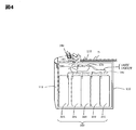
図4は、紙幣入出金装置100の内部構成と紙幣搬送経路を概略的に示す断面図である。
図示するように、紙幣入出金装置100の入出金機構部116には、紙幣Bの入金を受け付ける入金部120と紙幣Bを出金する出金部140とを隣接配置して備え、金庫110の筐体部112には、紙幣識別部170と搬送機構部180と紙幣収納部200とを収容して備える。こうして金庫110に収容された紙幣識別部170と紙幣収納部200は、筐体部112により、入出金機構部116の入金部120と出金部140から区画され、筐体部112において、紙幣識別部170が紙幣収納部200の上方側に位置する。
図示するように、紙幣入出金装置100の入出金機構部116には、紙幣Bの入金を受け付ける入金部120と紙幣Bを出金する出金部140とを隣接配置して備え、金庫110の筐体部112には、紙幣識別部170と搬送機構部180と紙幣収納部200とを収容して備える。こうして金庫110に収容された紙幣識別部170と紙幣収納部200は、筐体部112により、入出金機構部116の入金部120と出金部140から区画され、筐体部112において、紙幣識別部170が紙幣収納部200の上方側に位置する。
また図3に示すとおり、入金部120は、出金部140よりも紙幣識別部170側、即ち後面側に配置され、この入金部120と隣接配置された出金部140は、入金部120の側に壁部141を備える。この壁部141は、出金部140の内部を入金部120の側で覆い、その上端の基部141bに蓋体141cを隔てて備える。蓋体141cは、出金部140の開口上端を覆うよう開閉自在とされ、出金部140に搬送されてきた出金紙幣の飛び出しを防止する。壁部141は、入金部120の開口上端までしか延びておらず、蓋体141cにあってもその幅が狭くされている。よって、壁部141および蓋体141cは、顧客応対テーブルDを隔てた顧客K(図2参照)が入金部120の側から出金部140を眺める際の視線を遮らない。また、蓋体141cが出金部140全体を覆う形状になっておらず、その幅が狭い、かつ、中央位置付近に設けられているため、窓口係員Mの手の動線の妨げにならないことから入金部120への紙幣Bの投入の妨げにもならず操作性がよい。
紙幣識別部170は、紙幣の金種種別の他、記番号、紙幣真偽、破損状況(リジェクト要否)等を、入出金の過程で鑑別する。紙幣識別部170による紙幣識別は、例えば、紙幣をスキャンして得られる画像データ、紙幣の表面の凹凸形状、磁気特性、紫外線などに対する光学特性など種々の情報を利用して行うことができる。紙幣識別部170の識別結果は、後述の制御部190に出力され、紙幣搬送先のカセットの決定、リジェクト搬送等に用いられる。
搬送部に相当する搬送機構部180は、入金部120および出金部140から紙幣収納部200に掛けて、紙幣入金経路180INと紙幣出金経路180OUTとを形成する。図4に示すように、紙幣入金経路180INは、入金部120から紙幣識別部170に到る上流側入金経路181を備える。紙幣出金経路180OUTは、紙幣識別部170から出金部140に到る下流側出金経路186を備える。
これら経路を有する搬送機構部180は、上記の入出金経路にて入金部120と出金部140とを紙幣識別部170と紙幣収納部200とに接続して、紙幣を搬送する。紙幣収納部200は、TCR収納部201~205を備え、それぞれの収納部に紙幣を収納する。
図5は、紙幣入出金装置100の制御ブロック図の一例を示す説明図である。
紙幣入出金装置100は、機能ブロックとして、入金部120と、出金部140と、紙幣収納部200のTCR収納部201~205と、紙幣識別部170と、操作パネル118と、搬送機構部180と、制御部190とを有する。
紙幣入出金装置100は、機能ブロックとして、入金部120と、出金部140と、紙幣収納部200のTCR収納部201~205と、紙幣識別部170と、操作パネル118と、搬送機構部180と、制御部190とを有する。
入金部120は、紙幣が投入されることで紙幣を機構内部へ搬送するための機構であり、その内部に、紙幣繰り出し機構を有し、搬送機構部180を介してTCR収納部に紙幣を入金する。出金部140は、係員の指示によりTCR収納部201~205から繰り出した紙幣を出金するための機構である。
TCR収納部201~205は、金種別に設けられる。また、TCR収納部201~205は、自動取引処理装置の現金収納庫であるATM収納部と互換性を有する。そのため、TCR収納部201~205とATM収納部とを交換することにより、紙幣入出金装置100で回収された紙幣を、そのまま自動取引処理装置の取扱紙幣として運用することができる。
操作パネルは118、紙幣入出金装置100の入出金等に必要や情報や、紙幣入出金装置100のエラー情報等を表示するためのパネルである。なお、操作端末10の入出力部に表示する画面は、操作パネル118に表示してもよい。
搬送機構部180は、TCR収納部201~205ごとのゲート201bを初めとするゲート群と、紙幣搬送経路に複数設置した検知センサの検知センサ群188と、紙幣搬送を担う複数の駆動モータの駆動モータ群189とを備える。
検知センサ群188に含まれる検知センサは、紙幣入金経路180INや紙幣出金経路180OUTにて紙幣搬送状態を検知するほか、入金部120や出金部140における紙幣有無、TCR収納部201~205における紙幣収納枚数等を検知し、その検知信号を制御部190に出力する。
制御部190は、CPU191と、メモリ193とを有する。CPU191は、主に制御用のマイクロプロセッサからなる。CPU191は、入金部120や出金部140に含まれる紙幣送出・搬送に関与する駆動機器等の他、搬送機構部180のゲート群、駆動モータ群を、紙幣の入出金搬送に伴い駆動制御する。
メモリ193は、CPU191によって実行されるプログラム及び当該プログラムの実行に必要なデータを記憶する。また、メモリ193は、プログラムとCPU191との協働により、上位通信部195及びTCR収納部管理テーブル197といった機能部を構成する。CPU191は、紙幣入出金装置100での入出金取引実行時にTCR収納部管理テーブル197を参照し情報の更新を行う。
操作端末10は、係員が、紙幣入出金装置100に対し入出金等の処理指示や種々の情報を入出力するための端末である。なお、本実施形態では、紙幣入出金装置100と操作端末10とを別に図示しているが、操作端末10の有する機能部を全て紙幣入出金装置100が有し、係員は、操作端末10を介さずに処理を行うとしても良い。操作端末10は、入出力部11と、明細票を印字するための明細票印字部13と、制御部15とを有する。制御部15は、CPU17及びメモリ19からなり、メモリ19は、プログラムとCPU17との協働により、通信部21を構成する。
また、本実施形態では、紙幣入出金装置100と操作端末10とが一対応である例を図示しているが、金融機関等には、複数の紙幣入出金装置100が配置されていることが一般的であり、一台の操作端末10が、複数台の紙幣入出金装置100への入力や出力を行うこともできる。
自動取引処理装置では、係員を介さず顧客が入出金等の取引操作を行い、日に多量の入出金取引を取扱う。そのため、自動取引処理装置のATM収納部と交換するTCR収納部201~205に収納される紙幣の量が、多すぎ又は少なすぎると、ATM収納部の交換作業が頻繁に必要となり、その度に係員が自動取引処理装置を停止して交換作業を行わなければならない。そこで、本実施形態では、TCR収納部201~205の紙幣の収納量を管理し、ATM収納部の交換に適するTCR収納部を準備する。
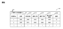
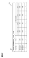
図6は、紙幣入出金装置100の有するTCR収納部管理テーブル197の一例を示す。
TCR収納部管理テーブル197は、紙幣入出金装置100のTCR収納部201~205の紙幣の収納状況や、紙幣の収納量を管理するための条件を記憶するテーブルである。
TCR収納部管理テーブル197は、紙幣入出金装置100のTCR収納部201~205の紙幣の収納状況や、紙幣の収納量を管理するための条件を記憶するテーブルである。
TCR収納部管理テーブル197は、収納部No.210と、金種211と、収納枚数212と、通知上限213と、通知下限214と、最大収納枚数215と、通知(○/×)情報216とから構成される。
収納部No.210は、紙幣入出金装置100のTCR収納部201~205を特定する番号である。金種211は、TCR収納部201~205に収納する紙幣の金種を示す。
収納枚数212は、TCR収納部201~205に収納されている紙幣の枚数を示す。なお、収納枚数212は、検知センサ群188の検知によって計数される。なお、本実施形態では、収納枚数212の値は、入金あるいは出金の取引実行時に更新されるものとするが、それに限られず、所定の時間毎に最新の情報に更新される仕様にしてもよい。
収納枚数212は、TCR収納部201~205に収納されている紙幣の枚数を示す。なお、収納枚数212は、検知センサ群188の検知によって計数される。なお、本実施形態では、収納枚数212の値は、入金あるいは出金の取引実行時に更新されるものとするが、それに限られず、所定の時間毎に最新の情報に更新される仕様にしてもよい。
通知上限213は、係員に対して通知を行う紙幣枚数の上限値(上限閾値)を示す。通知下限214は、係員に対して通知を行う紙幣枚数の下限値(下限閾値)を示す。即ち、制御部190は、TCR収納部201~205の紙幣の収納枚数が、通知上限213と通知下限214との範囲に属する場合、係員に対して通知を行う。
なお、通知上限213と通知下限214の値は、後述のカセット条件指定処理により、係員が指定する。係員は、紙幣入出金装置や自動取引処理装置の稼働場所、稼働時期、稼働方法や入出金傾向の特性等、実際の稼働実績を考慮して、最適な値を指定する。
本実施形態では、通知条件として以上の通知上限と通知下限とを設けることにより、自動取引処理装置の運用に適する枚数の紙幣が収納されるTCR収納部201~205を準備する。
最大収納枚数215は、TCR収納部201~205に収納できる最大の収納枚数の値を示す。
通知情報216は、TCR収納部201~205が、通知に適する状態にあるか否かを示す情報である。本実施形態では、収納枚数212が、通知上限213と通知下限214との範囲内にある場合、TCR収納部201~205がATM収納部の交換に適している状態であると判断し、係員に通知を行う。通知する状態を○で、通知しない状態を×で記憶する。
通知情報216は、TCR収納部201~205が、通知に適する状態にあるか否かを示す情報である。本実施形態では、収納枚数212が、通知上限213と通知下限214との範囲内にある場合、TCR収納部201~205がATM収納部の交換に適している状態であると判断し、係員に通知を行う。通知する状態を○で、通知しない状態を×で記憶する。
例えば、収納部No.1の千円紙幣を収納するTCR収納部は、現在の収納枚数が2468枚であり、通知上限2600枚と通知下限2400枚との間に該当するため、通知情報216は○となる。
図7は、制御部190が、TCR収納部201~205に通知条件を指定する際に行う条件指定処理の処理フローを示す図である。
まず、S701で、制御部190が、係員の入力によりTCR収納部201~205の条件指定の指示を受付けると、収納部選択画面800を表示する(S703)。係員は、収納部選択画面800を確認することにより、TCR収納部201~205の状態を見ながら、どのTCR収納部201~205に通知条件を指定するかを選択する。
まず、S701で、制御部190が、係員の入力によりTCR収納部201~205の条件指定の指示を受付けると、収納部選択画面800を表示する(S703)。係員は、収納部選択画面800を確認することにより、TCR収納部201~205の状態を見ながら、どのTCR収納部201~205に通知条件を指定するかを選択する。
次いで、S705で、制御部190は、収納部選択画面800において収納部が選択されたことを検知すると(S705:Yes)、通知条件設定画面900を表示する(S707)。係員は、通知条件設定画面900にて、TCR収納部201~205の通知条件(通知上限及び通知下限の値)を設定する。
通知条件は、上述の通り、係員が、紙幣入出金装置100や自動取引処理装置の稼働場所、稼働時期、稼働方法や入出金傾向の特性等の実際の稼働実績を考慮して、最適な値を各TCR収納部に対して指定する。また、予め定めた値を、全てのTCR収納部あるいは金種毎のTCR収納部に自動で設定するようにしてもよい。
次いで、通知条件が入力されると、制御部190は、入力された値を登録する(S709)。
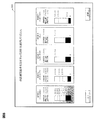
入力値の登録後及び収納部選択指示を受付けていない場合(S705:No)、S711で、明細票印字の指示を受付けているかを判断する。明細票には、TCR収納部201~205の紙幣の収納枚数や、通知条件等が印字される。印字される明細票の一例を図12に示す。明細票印字の指示を受付ける場合(S711:Yes)、明細票の印字を操作端末10に指示し、受付けていない場合(S711:No)、処理を終了する。
入力値の登録後及び収納部選択指示を受付けていない場合(S705:No)、S711で、明細票印字の指示を受付けているかを判断する。明細票には、TCR収納部201~205の紙幣の収納枚数や、通知条件等が印字される。印字される明細票の一例を図12に示す。明細票印字の指示を受付ける場合(S711:Yes)、明細票の印字を操作端末10に指示し、受付けていない場合(S711:No)、処理を終了する。
図8は、条件指定処理のS703で表示する収納部選択画面800の一例を示す。
収納部選択画面800には、紙幣入出金装置100に構成されるTCR収納部201~205の通知条件(通知上限及び通知下限の値)と現状の収納状態とが表示される。また、係員に対し通知条件を新規設定又は変更するTCR収納部201~205を選択するように誘導する情報が表示される。
収納部選択画面800には、紙幣入出金装置100に構成されるTCR収納部201~205の通知条件(通知上限及び通知下限の値)と現状の収納状態とが表示される。また、係員に対し通知条件を新規設定又は変更するTCR収納部201~205を選択するように誘導する情報が表示される。
係員は、TCR収納部201~205の紙幣の収納状態を見ながら、どのTCR収納部201~205に通知条件を指定するかを選択することができる。また、収納部選択画面800には、印刷ボタンが設けられ、係員は、印刷ボタンを選択することにより明細票を印字することができる。なお、本図面には図示していないが、全てのTCR収納部あるいは金種別のTCR収納部を一括で選択できるようにしてもよい。
図9は、条件指定処理のS707で表示する通知条件設定画面900の一例を示す。
通知条件設定画面900には、例えば、TCR収納部201~205の収納紙幣枚数と、通知条件と、通知条件の値を指定するためのテンキーとが表示される。係員は、テンキー入力により、選択したTCR収納部に対し通知条件を設定する。なお、通知条件の入力は、テンキーに限られず別途入力部を介して行うのでもよい。
通知条件設定画面900には、例えば、TCR収納部201~205の収納紙幣枚数と、通知条件と、通知条件の値を指定するためのテンキーとが表示される。係員は、テンキー入力により、選択したTCR収納部に対し通知条件を設定する。なお、通知条件の入力は、テンキーに限られず別途入力部を介して行うのでもよい。
また、通知条件の新規設定や設定変更は、紙幣入出金装置100の電源立ち上げ時に限られず、いつでも行うことができる。そのため、係員は、紙幣の収納状態を確認しながら、運用に適する通知条件を適宜設定することができる。
以上のように、本実施形態では、TCR収納部にATM収納部の運用に適する通知上限及び通知下限の値を適宜設定できるため、TCR収納部をATM収納部として柔軟に運用することができる。
図10は、制御部190が行う通知処理の処理フローの一例を示す。
まず、S1001で、取引開始を検知すると、検知した取引種類が入金/出金のいずれの取引であるかを判断する(S1003)。取引が入金取引である場合、入金部120に投入された紙幣を紙幣鑑別部170で鑑別し、紙幣をTCR収納部201~205に収納する(S1005)。取引が出金取引である場合、TCR収納部201~205から紙幣を繰り出し、出金部140に紙幣を搬送する。
まず、S1001で、取引開始を検知すると、検知した取引種類が入金/出金のいずれの取引であるかを判断する(S1003)。取引が入金取引である場合、入金部120に投入された紙幣を紙幣鑑別部170で鑑別し、紙幣をTCR収納部201~205に収納する(S1005)。取引が出金取引である場合、TCR収納部201~205から紙幣を繰り出し、出金部140に紙幣を搬送する。
次いで、S1009で、制御部190は、入出金取引後の情報でTCR収納部管理テーブル197を更新して、取引を終了する(S1011)。
次に、S1013で、制御部190は、TCR収納部管理テーブル197を参照して、収納枚数が、通知上限と通知下限との範囲内に属するか、即ち通知条件に該当しているかを判断する。
次に、S1013で、制御部190は、TCR収納部管理テーブル197を参照して、収納枚数が、通知上限と通知下限との範囲内に属するか、即ち通知条件に該当しているかを判断する。
通知条件に該当する場合(S1013:Yes)、S1015で係員通知画面1100を表示する。係員通知画面1100は、通知条件に該当するTCR収納部を係員に通知する画面である。係員通知画面1100については、図11を用いて後述する。
係員は、係員通知画面1100を確認することにより、ATM収納部の交換に適するTCR収納部201~205を即時に把握できる。また、通知条件に該当しない場合(S1013:No)、処理を終了する。
本実施形態では、入金又は出金取引の動作後に、通知条件に該当するか否かを判断するため、次の取引を実行する前に、事前に係員に対して運用の契機を通知することができる。また、入金又は出金取引実行する度、即ち紙幣の収納枚数に変動がある度に以上の通知処理を実行することにより、係員に対し運用の契機を取り残しなく通知することができる。
係員は、係員通知画面1100を確認することにより、ATM収納部の交換に適するTCR収納部201~205を即時に把握できる。また、通知条件に該当しない場合(S1013:No)、処理を終了する。
本実施形態では、入金又は出金取引の動作後に、通知条件に該当するか否かを判断するため、次の取引を実行する前に、事前に係員に対して運用の契機を通知することができる。また、入金又は出金取引実行する度、即ち紙幣の収納枚数に変動がある度に以上の通知処理を実行することにより、係員に対し運用の契機を取り残しなく通知することができる。
以上のように、本実施形態では、TCR収納部の紙幣量を管理し、ATM収納部の交換に適する紙幣量になると係員に通知することで、交換の契機を効果的に提案することができる。そのため、係員は、交換可能なTCR収納部を迅速かつ的確に把握することができ、TCR収納部とATM収納部との間で効率的に収納部を運用することができる。また、係員が、運用のためにTCR収納部に収納される紙幣量を調整する必要がないため、紙幣量を調整する際に生じていた違算や紙幣抜取等の不正を生じさせることなく、安全性の高い業務を遂行することができる。
図11は、通知処理のS1013で表示する係員通知画面1100の一例を示す。
係員通知画面1100では、係員が、通知条件に該当するTCR収納部201~205を即時に判別できるように、他のTCR収納部とは区別できる強調表示する等して通知を行う。また、印刷ボタンを選択することにより、TCR収納部201~205の収納情報を明細票に印字することができる。図11は、「収納部2」の収納枚数が、通知上限と通知下限との間に該当し、ATM収納部への運用に適している状態であることを示している。
係員通知画面1100では、係員が、通知条件に該当するTCR収納部201~205を即時に判別できるように、他のTCR収納部とは区別できる強調表示する等して通知を行う。また、印刷ボタンを選択することにより、TCR収納部201~205の収納情報を明細票に印字することができる。図11は、「収納部2」の収納枚数が、通知上限と通知下限との間に該当し、ATM収納部への運用に適している状態であることを示している。
図12は、印字される明細票1200の一例を示す。
明細票1200には、TCR収納部管理テーブル197の種々の情報が印字され、係員は、明細票1200に印字することによりTCR収納部201~205の収納状態を適宜確認することができる。
明細票1200には、TCR収納部管理テーブル197の種々の情報が印字され、係員は、明細票1200に印字することによりTCR収納部201~205の収納状態を適宜確認することができる。
また、係員は、TCR収納部をATM収納部として運用するタイミングを、紙幣入出金装置での顧客対応状況や自動取引処理装置の稼働状況を考慮して判断したい場合がある。そこで、以降では、TCR収納部が通知条件に該当した場合、係員にTCR収納部としての稼働を優先するかATM収納部の交換収納部としての運用を優先するかを選択させることができる稼働選択処理について説明する。
図13は、制御部190が行う稼働選択処理の処理フローを説明する図である。
S1001~S1015については、図10の通知処理と同様であるため説明を省略する。
S1001~S1015については、図10の通知処理と同様であるため説明を省略する。
通知条件に該当するTCR収納部が存在し、係員通知画面1100を表示すると、制御部190は、S1301で、紙幣入出金装置100に通知条件に該当するTCR収納部と同じ金種の他のTCR収納部が存在するかを判断する。他のTCR収納部がない場合(S1301:No)、稼働選択画面1400を表示する(S1303)。
また、他のTCR収納部がある場合(S1017:Yes)、稼働選択処理を終了する。なお、紙幣入出金装置100は、他のTCR収納部に収納される紙幣を使用して、入出金取引を継続する。
稼働選択画面1400は、紙幣入出金装置100としての稼働を継続あるいは中止するかを係員に判断させる画面である。他のTCR収納部がない場合、他の収納部を使って取引を継続することができないため、TCR収納部として運用を継続するか、ATM収納部の交換収納部として運用するかどうかを係員に選択させる必要があるためである。
図14は、稼働選択処理のS1303で表示する稼働選択画面1400の一例を示す。
稼働選択画面1400には、紙幣入出金装置100の稼働の継続又は中止を選択できる情報が表示される。また、通知条件に該当するTCR収納部の状態情報があわせて表示される。
稼働選択画面1400には、紙幣入出金装置100の稼働の継続又は中止を選択できる情報が表示される。また、通知条件に該当するTCR収納部の状態情報があわせて表示される。
以上のように、係員は、窓口での顧客対応状況や自動取引処理装置の稼働状況を考慮して、稼働選択画面により紙幣入出金装置の稼働を継続/中止するかを判断することができる。そのため、係員は、状況に応じた効率的な業務を遂行することができる。また、紙幣入出金装置は、係員により入出金操作される。そのため、係員は、次の入出金取引で取扱う紙幣量を確認し、その紙幣量を考慮した上で稼働の継続あるいは中止を判断することができる。
[第2の実施形態]
第2の実施形態では、紙幣収納庫に収納される紙幣量を管理すると共に、交換先として適している現金収納庫を特定することにより、紙幣入出金装置の紙幣収納庫を自動取引処理装置の現金収納庫として効率的に運用するものである。
第2の実施形態では、紙幣収納庫に収納される紙幣量を管理すると共に、交換先として適している現金収納庫を特定することにより、紙幣入出金装置の紙幣収納庫を自動取引処理装置の現金収納庫として効率的に運用するものである。
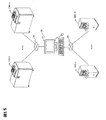
図15は、本実施形態の紙幣取扱システムの構成図を示す。
本実施形態のシステムは、紙幣入出金装置100と、自動取引処理装置300と、上位装置である管理装置50と、これらを接続するネットワーク60とから構成される。なお、紙幣入出金装置100及び自動取引処理装置300は、一又は複数台接続されるものとする。
本実施形態のシステムは、紙幣入出金装置100と、自動取引処理装置300と、上位装置である管理装置50と、これらを接続するネットワーク60とから構成される。なお、紙幣入出金装置100及び自動取引処理装置300は、一又は複数台接続されるものとする。
図16は、紙幣取扱システムの制御ブロック図の一例を示す説明図である。
紙幣入出金装置100は、第1の実施形態と同様であるため説明を省略する。
自動取引処理装置300は、機能ブロックとして、入金部301と、出金部303と、ATM収納部305と、紙幣識別部310と、操作パネル312と、搬送機構部314と、利用明細を印刷発行する明細書発行部320と、通帳を受付けて印字を行う通帳印字部322と、利用者の口座番号などの情報が記録された記録媒体であるカードを取り扱うカード部324と、制御部330とを有する。
紙幣入出金装置100は、第1の実施形態と同様であるため説明を省略する。
自動取引処理装置300は、機能ブロックとして、入金部301と、出金部303と、ATM収納部305と、紙幣識別部310と、操作パネル312と、搬送機構部314と、利用明細を印刷発行する明細書発行部320と、通帳を受付けて印字を行う通帳印字部322と、利用者の口座番号などの情報が記録された記録媒体であるカードを取り扱うカード部324と、制御部330とを有する。
制御部330は、CPU332とメモリ334とを有する。CPU332は、主に制御用のマイクロプロセッサからなる。CPU332は、入金部301、出金部303、明細書発行部320、通帳印字部322やカード部に含まれる駆動機器の他、搬送機構部314のゲート群305b、駆動モータ群318を駆動制御する。
メモリ334は、CPU332によって実行されるプログラム及び当該プログラムの実行に必要なデータを記憶する。また、メモリ334は、プログラムとCPU332との協働により、上位通信部336及び現金情報テーブル338といった機能部を構成する。CPU332は、入出金等の取引実行時に現金情報テーブル338を参照し情報の更新を行う。また、CPU332は、現金情報テーブル338を参照し、要件判断処理(図21)を実行する。
管理装置50は、紙幣入出金装置100及び自動取引処理装置300接続され、通知条件に該当する紙幣収納部がある場合に、運用に適するATM収納部を決定する。
管理装置50は、入出力部51と制御部52とを有する。係員は、入出力部51により紙幣入出金装置100や自動取引処理装置300に対して処理指示を与えることや、種々の情報を表示することができる。
管理装置50は、入出力部51と制御部52とを有する。係員は、入出力部51により紙幣入出金装置100や自動取引処理装置300に対して処理指示を与えることや、種々の情報を表示することができる。
制御部52は、CPU53とメモリ54とを有する。CPU53は、主に制御用のマイクロプロセッサからなる。メモリ54は、CPU53によって実行されるプログラム及び当該プログラムの実行に必要なデータを記憶し、プログラムとCPU53との協働により、通信部55と、接続装置テーブル56と、要件判断テーブル57といった機能部を構成する。CPU53は、要件判断テーブル57を参照し、通知処理(図20)を実行する。
図17は、自動取引処理装置300のメモリ334に格納される現金情報テーブル338の一例を示す。
現金情報テーブル338は、自動取引処理装置300で実行した取引の取引時間340と、取引種別342と、金種別の収納カセットの紙幣収納枚数344とからなる。
自動取引処理装置300で行われる取引には、入金取引や出金取引の他、振込取引や通帳印字等がある。本実施形態では、現金情報テーブル338は、全ての取引実行時に更新されるものとするが、ATM収納部305に収納される紙幣の枚数に変化があった取引実行時のみ更新されるものとしてもよい。
現金情報テーブル338は、自動取引処理装置300で実行した取引の取引時間340と、取引種別342と、金種別の収納カセットの紙幣収納枚数344とからなる。
自動取引処理装置300で行われる取引には、入金取引や出金取引の他、振込取引や通帳印字等がある。本実施形態では、現金情報テーブル338は、全ての取引実行時に更新されるものとするが、ATM収納部305に収納される紙幣の枚数に変化があった取引実行時のみ更新されるものとしてもよい。
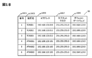
図18は、管理装置50のメモリ54に格納される接続装置テーブル56の一例を示す。
接続装置テーブル56は、管理番号1801と、装置名1803と、IPアドレス1805と、サブネットマスク1807と、デフォルトゲートウェイ1809とからなる。
接続装置テーブル56は、管理番号1801と、装置名1803と、IPアドレス1805と、サブネットマスク1807と、デフォルトゲートウェイ1809とからなる。
装置名1803は、管理装置50に接続される装置名称を示す。IPアドレス1805は、ネットワークに接続される装置に割り振られる識別番号である。サブネットマスク1807とは、IPアドレスと、ネットワークを示すネットワークアドレスと、ホストを示すホストアドレスとを識別するための値である。デフォルトゲートウェイ1809とは、紙幣入出金装置100と自動取引処理装置300とが接続する際に、通信対象が不明である場合に送信する中継機器のIPアドレスを示す。
紙幣入出金装置100は、サブネットマスク1807により接続先の自動取引処理装置300が、同じネットワーク60内に存在するかを判断することができる。また、紙幣入出金装置100は、デフォルトゲートウェイ1809を中継することで異なるネットワーク60に存在する自動取引処理装置300と通信できる。例えば、ネットワークがフロアごとに区切られた店舗内であっても、紙幣入出金装置100は、デフォルトゲートウェイを中継することにより他のフロアに存在する自動取引処理装置300の現金情報テーブル338の情報を取得できる。
図19は、管理装置50に表示する接続先表示画面1900の一例を示す。
係員は、接続先表示画面1900により管理装置50と接続する紙幣入出金装置100や自動取引処理装置300の追加や削除等の設定変更を柔軟に行うことができる。また、接続される装置群を一覧で確認することができるため、容易にシステムを管理することができる。
係員は、接続先表示画面1900により管理装置50と接続する紙幣入出金装置100や自動取引処理装置300の追加や削除等の設定変更を柔軟に行うことができる。また、接続される装置群を一覧で確認することができるため、容易にシステムを管理することができる。
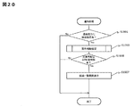
図20は、制御部52が行う第2の実施形態の通知処理の処理フローの一例を示す。
なお、本実施形態のTCR収納部201~205も第1の実施形態と同様に、通知条件となる通知上限及び通知下限が指定される。但し、条件指定の方法は、第1の実施形態の条件指定処理(図7)と同様であるため説明を省略する。
なお、本実施形態のTCR収納部201~205も第1の実施形態と同様に、通知条件となる通知上限及び通知下限が指定される。但し、条件指定の方法は、第1の実施形態の条件指定処理(図7)と同様であるため説明を省略する。
S1901で、制御部52は、通知条件に該当するTCR収納部201~205を有する紙幣入出金装置100を検知する場合(S1901:Yes)、S1903で要件判断処理を行う。
要件判断処理とは、通知対象となったTCR収納部201~205と交換可能な自動取引処理装置300のATM収納部305を決定する処理である。要件判断処理の詳細については、図21を用いて後述する。本実施形態では、要件判断処理を行うことにより、交換可能なTCR収納部をATM収納部へ効率良く運用することができる。
要件判断処理により、TCR収納部201~205と交換可能なATM収納部305が有ると判断されると(S1905:Yes)、S1907で、入出力部51に候補一覧画面を表示する。また、交換可能なATM収納部305が無いと判断されると(S1905:No)、処理を終了する。
候補一覧画面には、通知対象となったTCR収納部201~205の情報や、該TCR収納部の交換候補となるATM収納部305を表示する。候補一覧画面については、図23で後述する。
候補一覧画面には、通知対象となったTCR収納部201~205の情報や、該TCR収納部の交換候補となるATM収納部305を表示する。候補一覧画面については、図23で後述する。
係員は、候補一覧画面を確認することにより、通知条件に該当するTCR収納部の有無と共に、該TCR収納部と交換できるATM収納部の候補を即時に知ることができる。そのため、係員が、交換先となるATM収納部を逐次検討することなく収納部の交換作業を行うことができ、TCR収納部を効率よくATM収納部として運用することができる。
図21は、通知処理のS1903で行う要件判断処理(S1903)のフローの一例を示す。
要件判断処理では、通知対象となったTCR収納部201~205と交換可能なATM収納部305を決定する。
要件判断処理では、通知対象となったTCR収納部201~205と交換可能なATM収納部305を決定する。
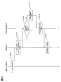
まず、S2001で、紙幣入出金装置100は、通知条件に一致するTCR収納部がある場合、管理装置50に対して、リクエスト情報を送信する。リクエスト情報には、少なくとも通知条件に該当したTCR収納部を有する紙幣入出金装置名と、該TCR収納部に収納される金種情報と、装填枚数とが含まれる。ここでは、紙幣入出金装置のTCR収納部に収納される紙幣の枚数を装填枚数と呼ぶ。その他、通知条件に該当した時間情報等をリクエスト情報として送信しても良い。
管理装置50は、リクエスト情報を受信すると、自動取引処理装置300に対し、リクエスト情報及び交換カセット候補確認要求を送信する(S2003)。
交換カセット候補確認要求は、紙幣入出金装置100のTCR収納部と交換可能なATM収納部305が存在するかを確認するための問い合わせ通知である。なお、本実施形態では、管理装置50を介してリクエスト情報及び交換カセット候補確認要求を自動取引処理装置300に通知するものとしているが、紙幣入出金装置100から直接自動取引処理装置300に通知するものとしてもよい。
交換カセット候補確認要求は、紙幣入出金装置100のTCR収納部と交換可能なATM収納部305が存在するかを確認するための問い合わせ通知である。なお、本実施形態では、管理装置50を介してリクエスト情報及び交換カセット候補確認要求を自動取引処理装置300に通知するものとしているが、紙幣入出金装置100から直接自動取引処理装置300に通知するものとしてもよい。
自動取引処理装置300は、受信したリクエスト情報及び交換カセット候補確認要求により、通知条件に該当したTCR収納部と同じ金種のATM収納部305を抽出する。そして、通知条件に該当したTCR収納部の装填枚数と、抽出されたATM収納部305の収納枚数とを比較する(S2005)。
なお、自動取引処理装置300に同じ金種のATM収納部305が複数存在する場合、それらの中で収納枚数が一番少ないATM収納部305における収納枚数を、装填枚数と比較するものとする。
ATM収納部305の収納枚数が、TCR収納部201~205の装填枚数より少ない場合(S2005:Yes)、S2007で、該ATM収納部305を交換先となる収納部の候補に決定する。
S2009で、自動取引処理装置300は、管理装置50に対し交換収納部候補情報を送信する。交換収納部候補情報は、少なくとも交換先のATM収納部305を有する自動取引処理装置300を特定する情報と、該ATM収納部305が収納している紙幣の金種と、その収納枚数とを含む。
S2009で、自動取引処理装置300は、管理装置50に対し交換収納部候補情報を送信する。交換収納部候補情報は、少なくとも交換先のATM収納部305を有する自動取引処理装置300を特定する情報と、該ATM収納部305が収納している紙幣の金種と、その収納枚数とを含む。
次いで、S2011で、管理装置50は、交換収納部候補情報により要件判断テーブル57を更新する。要件判断テーブル57は、通知条件に該当したTCR収納部と、該TCR収納部と交換可能なATM収納部の情報を集約するものである。
以上のように、本実施形態では、要件判断処理を行うことにより、通知対象となったTCR収納部と交換可能なATM収納部を自動かつ即時に抽出することができる。
なお、本実施形態では、紙幣入出金装置が、S2001で、リクエスト情報を送信することを契機に自動取引処理装置の交換収納部候補を決定しているがこれに限られない。例えば、紙幣量の過不足あるATM収納部を検知すると、紙幣入出金装置にリクエストを送信し、通知条件に該当するTCR収納部を抽出するとしてもよい。
図22は、要件判断テーブル57の一例を示す図である。
要件判断テーブル57は、管理装置50のメモリ54に格納され、候補一覧画面2300を表示する際の情報となる。要件判断テーブル57は、リクエスト情報58と交換収納部候補情報59とから構成される。
要件判断テーブル57は、管理装置50のメモリ54に格納され、候補一覧画面2300を表示する際の情報となる。要件判断テーブル57は、リクエスト情報58と交換収納部候補情報59とから構成される。
リクエスト情報58は、要件判断処理のS2001において、紙幣入出金装置100から管理装置50に送信される情報である。リクエスト情報58には、通知条件に該当したTCR収納部を有する紙幣入出金装置名と、該TCR収納部に収納される金種情報と、装填枚数とが含まれる。
交換収納部候補情報59は、要件判断処理のS2009において、自動取引処理装置300から管理装置50に送信される情報である。
交換収納部候補情報59は、装置名と、金種と、収納枚数とからなる。装置名は、交換候補として抽出されたATM収納部305を有する自動取引処理装置300の名称を示す。金種及び収納枚数は、該ATM収納部305が収納する紙幣の金種及び枚数を示す。
交換収納部候補情報59は、装置名と、金種と、収納枚数とからなる。装置名は、交換候補として抽出されたATM収納部305を有する自動取引処理装置300の名称を示す。金種及び収納枚数は、該ATM収納部305が収納する紙幣の金種及び枚数を示す。
なお、紙幣入出金装置から送信されるリクエスト情報に対して、交換先となるATM収納部が複数抽出される場合もある。図21は、「TCR001」のリクエスト情報に対し、交換先として3つの自動取引処理装置300のATM収納部305が決定された様子を示す。
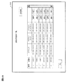
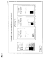
図23は、管理装置50の入出力部51に表示される候補一覧画面2300の一例を示す。
候補一覧画面2300には、通知条件に該当したTCR収納部201~205の収納状態が示される。また、交換候補として抽出されたATM収納部305の収納状態が、あわせて表示される。
交換候補となるATM収納部305が複数ある場合、収納枚数の少ないATM収納部305から順に表示してもよいし、収納枚数が最小のATM収納部305を強調表示してもよい。
候補一覧画面2300には、通知条件に該当したTCR収納部201~205の収納状態が示される。また、交換候補として抽出されたATM収納部305の収納状態が、あわせて表示される。
交換候補となるATM収納部305が複数ある場合、収納枚数の少ないATM収納部305から順に表示してもよいし、収納枚数が最小のATM収納部305を強調表示してもよい。
以上のように、本実施形態では、紙幣入出金装置で通知条件に該当するTCR収納部を通知すると共に、交換先の候補となる自動取引処理装置のATM収納部を抽出して通知する。そのため、係員は、通知情報を確認することにより、TCR収納部の交換の契機を図ることや、交換先となるATM収納部を逐次検討する必要がない。また、自動取引処理装置での取引が困難になる前に交換作業を行うこともでき、装置を停止させて顧客の取引を制限してしまう時間を低減することもできる。また、交換の際に、TCR収納部の紙幣を集約/仕分けする調整作業を行う必要もないため、効率的に収納部を運用することができる共に、違算や不正のない、安全性の高い業務を遂行することができる。
また、第1の実施形態の稼働選択処理を第2の実施形態に適用することもできる。
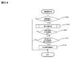
図24は、第2の実施形態の稼働選択処理を説明する処理フローの一例を示す。
S1901~S1905については、図20の通知処理と同様であるため説明を省略する。
図24は、第2の実施形態の稼働選択処理を説明する処理フローの一例を示す。
S1901~S1905については、図20の通知処理と同様であるため説明を省略する。
S1905で、通知条件に該当したTCR収納部201~205と交換可能なATM収納部305が有る場合、S2401で、該TCR収納部に収納する金種と同じ金種を収納する他のTCR収納部が有るかを判断する。
通知条件に該当したTCR収納部と同じ金種の紙幣を収納するTCR収納部がない場合(S2401:No)、S2403で稼働選択画面を入出力部に表示する。また、通知条件に該当したTCR収納部と同じ金種を収納するTCR収納部がある場合(S2401:Yes)、処理を終了する。
稼働選択画面は、第1の実施形態の図14と同様に、紙幣入出金装置100の稼働の継続又は中止を選択できる情報を表示する画面である。TCR収納部が通知条件に該当し、交換可能なATM収納部が存在していても、同じ金種の紙幣を収納するTCR収納部が無い場合、紙幣入出金装置100での取引を優先するか、ATM収納部との交換を優先するかを係員に判断させることができる。
また、以上では、交換可能な自動取引処理装置のATM収納部を決定し、紙幣入出金装置のTCR収納庫を運用する手法について説明したが、本手法は、自動取引処理装置間を含む自動装置間で現金収納部を運用する際にも適用することもできる。例えば、一の自動取引処理装置のATM収納部での紙幣収納量が、通知条件に該当することを検知すると、他の自動取引処理装置のATM収納部の収納状態を把握して交換収納部候補を決定するようにしても良い。
以上、本発明を実施するための形態を説明したが、本発明はこれらの例に限定されるものではなく、その趣旨を逸脱することのない範囲で種々の構成や動作を適用可能である。
また、実施形態における各機能部は、プログラムとCPUの協働によって実現する例について説明したが、これらの一部や全部をハードウェアとして実現することも可能である。
さらに、実施形態において各種テーブル形式で管理する情報は、テーブル形式に限られるものではない。また、各種情報は、各装置の入出力部に出力することができる。
また、実施形態における各機能部は、プログラムとCPUの協働によって実現する例について説明したが、これらの一部や全部をハードウェアとして実現することも可能である。
さらに、実施形態において各種テーブル形式で管理する情報は、テーブル形式に限られるものではない。また、各種情報は、各装置の入出力部に出力することができる。
10…操作端末
11、51…入出力部
13…明細票印字部
15、52、330…制御部
17、52、191、332…CPU
19、54、193、334…メモリ
21、55…通信部
50…管理装置
56…接続装置テーブル
57…要件判断テーブル
60…ネットワーク
100…紙幣入出金装置
118、312…操作パネル
120、301…入金部
140、303…出金部
170、310…紙幣識別部
180、314…搬送機構部
195、336…上位通信部
197…TCR収納部管理テーブル
300…自動取引処理装置
320…明細書発行部
322…通帳印字部
324…カード部
338…現金情報テーブル
11、51…入出力部
13…明細票印字部
15、52、330…制御部
17、52、191、332…CPU
19、54、193、334…メモリ
21、55…通信部
50…管理装置
56…接続装置テーブル
57…要件判断テーブル
60…ネットワーク
100…紙幣入出金装置
118、312…操作パネル
120、301…入金部
140、303…出金部
170、310…紙幣識別部
180、314…搬送機構部
195、336…上位通信部
197…TCR収納部管理テーブル
300…自動取引処理装置
320…明細書発行部
322…通帳印字部
324…カード部
338…現金情報テーブル
Claims (12)
- 紙幣の入金を受付ける入金部と、
紙幣を出金する出金部と、
現金取引を実行する自動取引処理装置の現金収納部と交換可能な紙幣収納部と、
入出金取引の指示を受付ける入出力部と、
制御部とを有し、
前記制御部は、前記紙幣収納部に収納される紙幣収納量が、第1の閾値と第2の閾値との間に属することを検知すると、前記紙幣収納部が前記現金収納部と交換可能であることを通知する通知画面を前記入出力部に表示することを特徴とする紙幣入出金装置。 - 前記制御部は、前記入金部で受付けた紙幣を前記紙幣収納部に収納した後あるいは前記紙幣収納部から繰り出した紙幣を前記出金部に出金した後、前記紙幣収納部に収納される紙幣収納量が、前記第1の閾値と前記第2の閾値との間に属するかを検知することを特徴とする請求項1に記載の紙幣入出金装置。
- 前記制御部は、前記紙幣収納部に収納される紙幣収納量が、前記第1の閾値と前記第2の閾値との間に属することを検知すると、前記入出金取引の継続又は中止の指示を受付けることを特徴とする請求項1又は2に記載の紙幣入出金装置。
- 前記紙幣収納部を複数有し、
前記制御部は、一の紙幣収納部に収納される紙幣収納量が、前記第1の閾値と前記第2の閾値との間に属することを検知すると、前記一の紙幣収納部に収納される紙幣の種別と同じ種別の紙幣を収納する他の紙幣収納部の有無を判断し、前記他の紙幣収納部が無い場合、前記入出金取引の継続又は中止の指示を受付ける選択画面を前記入出力部に表示することを特徴とする請求項3に記載の紙幣入出金装置。 - 前記制御部は、前記他の紙幣収納部が有る場合、前記他の紙幣収納部に収納される紙幣により前記入出金取引を実行することを特徴とする請求項4に記載の紙幣入出金装置。
- 前記通知画面には、少なくとも前記紙幣収納量、前記第1の閾値及び前記第2の閾値の情報が含まれることを特徴とする請求項1乃至5に記載の紙幣入出金装置。
- 前記制御部は、前記第1の閾値及び前記第2の閾値の指定指示を受付けると、前記第1の閾値及び前記第2の閾値の値を指定する条件指定画面を前記入出力部に表示することを特徴とする請求項1乃至6に記載の紙幣入出金装置。
- 管理装置と前記管理装置に接続される複数の自動装置とからなる紙幣取扱システムであって、
前記管理装置は、入出力部と第1制御部とを有し、
前記複数の自動装置の各々は、紙幣の入金を受付ける入金部と、紙幣を出金する出金部と、紙幣を収納する紙幣収納部と、第2制御部とを有し、
前記第2制御部が、前記紙幣収納部に収納される紙幣収納量が第1の閾値と第2の閾値との間に属することを検知すると、
前記第1制御部は、前記紙幣収納部を有する自動装置と異なる他の自動装置の紙幣収納部から前記紙幣収納部と交換可能な交換収納部を特定する交換収納部情報により前記交換収納部を通知する通知画面を前記入出力部に表示することを特徴とする紙幣取扱システム。 - 前記第1制御部は、前記紙幣収納部に収納される紙幣と同じ種別の紙幣を収納し、前記紙幣収納量よりも少ない量の紙幣を収納する紙幣収納部を前記交換収納部に決定することを特徴とする請求項8に記載の紙幣取扱システム。
- 前記第1制御部は、前記交換収納部を決定すると、前記紙幣収納部を有する自動装置が、前記紙幣収納部に収納される紙幣の種別と同じ種別の紙幣を収納する他の紙幣収納部を有するかを判断し、前記他の紙幣収納部を有しない場合、該自動装置における入出金取引を継続又は中止する指示を受付ける選択画面を、前記入出力部に表示することを特徴とする請求項8又は9に記載の紙幣取扱システム。
- 前記他の紙幣収納部を有する場合、
前記第1制御部は、前記他の紙幣収納部に収納される紙幣により前記入出金取引を実行することを特徴とする請求項10に記載の紙幣取扱システム。 - 前記通知画面には、前記紙幣収納部と、一又は複数の前記交換収納部の紙幣の収納情報が含まれることを特徴とする請求項8乃至11に記載の紙幣取扱システム。
Applications Claiming Priority (2)
| Application Number | Priority Date | Filing Date | Title |
|---|---|---|---|
| JP2015129451A JP6464047B2 (ja) | 2015-06-29 | 2015-06-29 | 紙幣入出金装置及び紙幣取扱システム |
| JP2015-129451 | 2015-06-29 |
Publications (1)
| Publication Number | Publication Date |
|---|---|
| WO2017002710A1 true WO2017002710A1 (ja) | 2017-01-05 |
Family
ID=57608467
Family Applications (1)
| Application Number | Title | Priority Date | Filing Date |
|---|---|---|---|
| PCT/JP2016/068744 Ceased WO2017002710A1 (ja) | 2015-06-29 | 2016-06-24 | 紙幣入出金装置及び紙幣取扱システム |
Country Status (2)
| Country | Link |
|---|---|
| JP (1) | JP6464047B2 (ja) |
| WO (1) | WO2017002710A1 (ja) |
Citations (2)
| Publication number | Priority date | Publication date | Assignee | Title |
|---|---|---|---|---|
| JPS61208193A (ja) * | 1985-03-12 | 1986-09-16 | 株式会社東芝 | 紙幣処理システム |
| JP2011076416A (ja) * | 2009-09-30 | 2011-04-14 | Nec Corp | 現金自動取引装置、現金自動取引方法、及びプログラム |
-
2015
- 2015-06-29 JP JP2015129451A patent/JP6464047B2/ja not_active Expired - Fee Related
-
2016
- 2016-06-24 WO PCT/JP2016/068744 patent/WO2017002710A1/ja not_active Ceased
Patent Citations (2)
| Publication number | Priority date | Publication date | Assignee | Title |
|---|---|---|---|---|
| JPS61208193A (ja) * | 1985-03-12 | 1986-09-16 | 株式会社東芝 | 紙幣処理システム |
| JP2011076416A (ja) * | 2009-09-30 | 2011-04-14 | Nec Corp | 現金自動取引装置、現金自動取引方法、及びプログラム |
Also Published As
| Publication number | Publication date |
|---|---|
| JP2017016225A (ja) | 2017-01-19 |
| JP6464047B2 (ja) | 2019-02-06 |
Similar Documents
| Publication | Publication Date | Title |
|---|---|---|
| JP3950742B2 (ja) | 紙幣取扱装置 | |
| KR100877272B1 (ko) | 지엽류 처리 시스템 | |
| JP4007842B2 (ja) | 金融営業店における貨幣処理システム | |
| WO2010107656A1 (en) | Efficient movement and storage of funds | |
| JPH0434696A (ja) | 現金処理システム | |
| WO2013153572A1 (ja) | 紙葉類処理装置 | |
| WO2018043048A1 (ja) | 現金運用管理システム | |
| JP4549702B2 (ja) | 自動取引装置の取引縮退処理方法、そのシステム及びその運営サーバ | |
| CN101097639B (zh) | 纸张类处理装置及系统 | |
| JP2012203666A (ja) | 紙幣処理装置および紙幣処理方法 | |
| JP5085983B2 (ja) | 現金管理装置およびそれを用いた現金管理システム | |
| JP6527671B2 (ja) | 紙葉類管理装置、紙葉類処理システム及び紙葉類管理方法 | |
| JP4826032B2 (ja) | 現金管理システム及び現金管理方法 | |
| JP2004318518A (ja) | 紙幣運用システムおよびそのプログラム | |
| JP6268057B2 (ja) | 取引処理装置及び取引システム | |
| JP5087889B2 (ja) | 現金処理装置 | |
| JP6464047B2 (ja) | 紙幣入出金装置及び紙幣取扱システム | |
| JP7524722B2 (ja) | 現金処理装置および現金処理システム | |
| CN104751563A (zh) | 自助设备及自助设备的轧账方法 | |
| JP2008065627A (ja) | 現金処理装置 | |
| JP5267637B2 (ja) | 現金処理装置 | |
| JP2004355062A (ja) | 紙幣取扱装置及び現金自動取引装置 | |
| JPH0644442A (ja) | 現金管理システム | |
| JP5396303B2 (ja) | 自動取引装置 | |
| JP2013242628A (ja) | 現金自動取引装置 |
Legal Events
| Date | Code | Title | Description |
|---|---|---|---|
| 121 | Ep: the epo has been informed by wipo that ep was designated in this application |
Ref document number: 16817818 Country of ref document: EP Kind code of ref document: A1 |
|
| NENP | Non-entry into the national phase |
Ref country code: DE |
|
| 122 | Ep: pct application non-entry in european phase |
Ref document number: 16817818 Country of ref document: EP Kind code of ref document: A1 |