WO2017002228A1 - 車両制御装置及び車両制御方法 - Google Patents
車両制御装置及び車両制御方法 Download PDFInfo
- Publication number
- WO2017002228A1 WO2017002228A1 PCT/JP2015/068982 JP2015068982W WO2017002228A1 WO 2017002228 A1 WO2017002228 A1 WO 2017002228A1 JP 2015068982 W JP2015068982 W JP 2015068982W WO 2017002228 A1 WO2017002228 A1 WO 2017002228A1
- Authority
- WO
- WIPO (PCT)
- Prior art keywords
- vehicle
- engine
- brake
- starter
- actuator
- Prior art date
- Legal status (The legal status is an assumption and is not a legal conclusion. Google has not performed a legal analysis and makes no representation as to the accuracy of the status listed.)
- Ceased
Links
Images


Classifications
-
- B—PERFORMING OPERATIONS; TRANSPORTING
- B60—VEHICLES IN GENERAL
- B60T—VEHICLE BRAKE CONTROL SYSTEMS OR PARTS THEREOF; BRAKE CONTROL SYSTEMS OR PARTS THEREOF, IN GENERAL; ARRANGEMENT OF BRAKING ELEMENTS ON VEHICLES IN GENERAL; PORTABLE DEVICES FOR PREVENTING UNWANTED MOVEMENT OF VEHICLES; VEHICLE MODIFICATIONS TO FACILITATE COOLING OF BRAKES
- B60T7/00—Brake-action initiating means
- B60T7/12—Brake-action initiating means for automatic initiation; for initiation not subject to will of driver or passenger
-
- B—PERFORMING OPERATIONS; TRANSPORTING
- B60—VEHICLES IN GENERAL
- B60T—VEHICLE BRAKE CONTROL SYSTEMS OR PARTS THEREOF; BRAKE CONTROL SYSTEMS OR PARTS THEREOF, IN GENERAL; ARRANGEMENT OF BRAKING ELEMENTS ON VEHICLES IN GENERAL; PORTABLE DEVICES FOR PREVENTING UNWANTED MOVEMENT OF VEHICLES; VEHICLE MODIFICATIONS TO FACILITATE COOLING OF BRAKES
- B60T8/00—Arrangements for adjusting wheel-braking force to meet varying vehicular or ground-surface conditions, e.g. limiting or varying distribution of braking force
- B60T8/17—Using electrical or electronic regulation means to control braking
- B60T8/1755—Brake regulation specially adapted to control the stability of the vehicle, e.g. taking into account yaw rate or transverse acceleration in a curve
-
- F—MECHANICAL ENGINEERING; LIGHTING; HEATING; WEAPONS; BLASTING
- F02—COMBUSTION ENGINES; HOT-GAS OR COMBUSTION-PRODUCT ENGINE PLANTS
- F02D—CONTROLLING COMBUSTION ENGINES
- F02D29/00—Controlling engines, such controlling being peculiar to the devices driven thereby, the devices being other than parts or accessories essential to engine operation, e.g. controlling of engines by signals external thereto
- F02D29/02—Controlling engines, such controlling being peculiar to the devices driven thereby, the devices being other than parts or accessories essential to engine operation, e.g. controlling of engines by signals external thereto peculiar to engines driving vehicles; peculiar to engines driving variable pitch propellers
-
- F—MECHANICAL ENGINEERING; LIGHTING; HEATING; WEAPONS; BLASTING
- F02—COMBUSTION ENGINES; HOT-GAS OR COMBUSTION-PRODUCT ENGINE PLANTS
- F02N—STARTING OF COMBUSTION ENGINES; STARTING AIDS FOR SUCH ENGINES, NOT OTHERWISE PROVIDED FOR
- F02N11/00—Starting of engines by means of electric motors
- F02N11/08—Circuits specially adapted for starting of engines
-
- F—MECHANICAL ENGINEERING; LIGHTING; HEATING; WEAPONS; BLASTING
- F02—COMBUSTION ENGINES; HOT-GAS OR COMBUSTION-PRODUCT ENGINE PLANTS
- F02N—STARTING OF COMBUSTION ENGINES; STARTING AIDS FOR SUCH ENGINES, NOT OTHERWISE PROVIDED FOR
- F02N11/00—Starting of engines by means of electric motors
- F02N11/10—Safety devices
-
- F—MECHANICAL ENGINEERING; LIGHTING; HEATING; WEAPONS; BLASTING
- F02—COMBUSTION ENGINES; HOT-GAS OR COMBUSTION-PRODUCT ENGINE PLANTS
- F02N—STARTING OF COMBUSTION ENGINES; STARTING AIDS FOR SUCH ENGINES, NOT OTHERWISE PROVIDED FOR
- F02N15/00—Other power-operated starting apparatus; Component parts, details, or accessories, not provided for in, or of interest apart from groups F02N5/00 - F02N13/00
-
- Y—GENERAL TAGGING OF NEW TECHNOLOGICAL DEVELOPMENTS; GENERAL TAGGING OF CROSS-SECTIONAL TECHNOLOGIES SPANNING OVER SEVERAL SECTIONS OF THE IPC; TECHNICAL SUBJECTS COVERED BY FORMER USPC CROSS-REFERENCE ART COLLECTIONS [XRACs] AND DIGESTS
- Y02—TECHNOLOGIES OR APPLICATIONS FOR MITIGATION OR ADAPTATION AGAINST CLIMATE CHANGE
- Y02T—CLIMATE CHANGE MITIGATION TECHNOLOGIES RELATED TO TRANSPORTATION
- Y02T10/00—Road transport of goods or passengers
- Y02T10/10—Internal combustion engine [ICE] based vehicles
- Y02T10/40—Engine management systems
Definitions
- the present invention relates to a vehicle control device and a vehicle control method for executing control for stopping an engine while a vehicle is running.
- Japanese Patent Application Laid-Open No. 2004-044800 discloses a drive unit that interrupts transmission of an engine, a brake, and torque and stops the engine in order to improve fuel efficiency when a coasting operation of the vehicle is detected.
- the starter is driven to restart the engine.
- the engine control for driving the starter may be executed at the timing when the control for automatically driving the actuator is executed. In such a situation, there is a concern that the power consumption increases rapidly and the performance of the battery decreases.
- the present invention has been made in view of such circumstances, and an object of the present invention is to provide a vehicle control device and a vehicle control method that suppress the promotion of battery deterioration while improving fuel efficiency while the vehicle is running.
- the vehicle control device drives the starter when the actuator is operated by the brake control unit after the engine is stopped and the brake control unit drives the actuator according to the running state of the vehicle.
- FIG. 1 is a circuit diagram showing an example of the configuration of the vehicle control device according to the first embodiment of the present invention.
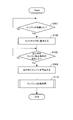
- FIG. 2 is a flowchart showing an example of a vehicle control method in the present embodiment.
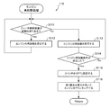
- FIG. 3 is a flowchart illustrating an example of an engine restart process executed in the vehicle control method.
- FIG. 4 is a flowchart illustrating an example of an engine restart process according to the second embodiment of the present invention.
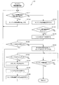
- FIG. 5 is a flowchart showing an example of an engine restart process according to the third embodiment of the present invention.
- FIG. 1 is a circuit diagram showing an example of the configuration of the vehicle control device according to the first embodiment of the present invention.
- the vehicle control device 100 is a vehicle braking device that executes engine control for automatically stopping the engine while the vehicle is running.
- the vehicle control device 100 When the ignition key of the vehicle is switched from OFF (OFF) to ON (ON) by the driver, the vehicle control device 100 enters a driving state in which the driver drives the vehicle and starts the engine. Then, the accelerator pedal is depressed and the vehicle travels. The vehicle control device 100 temporarily stops the engine when a predetermined condition is satisfied in the traveling state of the vehicle.
- the vehicle control device 100 stops the engine when the amount of depression of the accelerator pedal becomes zero while the vehicle is traveling, and then restarts the engine when the accelerator pedal is depressed.
- engine control is referred to as “coating stop control”. Stopping the engine while the vehicle is traveling is called “coasting stop”, and restarting the engine from the coasting stop is called “coasting start”.
- Vehicle control device 100 includes an alternator 10, a starter 11, a brake drive device 12, an electrical component 13, a power supply circuit 20, and a controller 30.
- the power supply circuit 20 includes a first battery 21, a second battery 22, and a switch 23.
- the alternator 10 is a generator that generates electric power by rotating the engine.
- the alternator 10 may be driven to generate electric power so that braking force acts on the vehicle when the vehicle is decelerated.
- the alternator 10 charges the first battery 21 with the generated power.
- the alternator 10 charges the second battery 22 with the generated power via the switch 23.
- the alternator 10 is disconnected from the engine in the coasting stop state. For this reason, power generation is not performed by the alternator 10 during the coasting stop.
- the starter 11 is an activation device that starts (cranks) the engine.
- the starter 11 is realized by a starter motor, for example.
- the starter 11 is disposed in the vicinity of the engine and is controlled by the controller 30.
- the starter 11 is connected to the first battery 21 in parallel.
- the starter 11 is driven using the power output from the first battery 21.
- the starter 11 cranks the engine and starts the engine.
- the starter 11 restarts the engine as necessary after the coasting is stopped. Examples of conditions for restarting the engine include a case where the accelerator pedal of the vehicle is depressed, and a case where the brake pedal is released from the driver's foot.
- the brake drive device 12 constitutes an actuator that brakes the vehicle.
- the brake drive device 12 has a mechanism for pressing a wheel provided in the vehicle.
- the brake drive device 12 is connected in parallel to the second battery 22.
- the brake drive device 12 includes an electric pump that raises the brake pressure in the actuator to a predetermined target pressure required for braking the vehicle.
- the electric pump of the brake drive device 12 is operated by at least the electric power output from the second battery 22.
- the brake drive device 12 is controlled by the controller 30. For example, the brake driving device 12 is driven when a brake pedal is depressed by the driver.
- the brake drive device 12 decelerates or stops according to a command from the controller 30 when the vehicle can come into contact with the vehicle ahead. To be driven.
- the controller 30 controlling the operation of the brake drive device 12 in accordance with the positional relationship between the vehicle ahead and its own vehicle regardless of the driver's intention is called “automatic brake control”.
- VDC Vehicle Dynamics Control
- the brake drive device 12 is driven when automatic brake control, VDC control, or the like is activated.
- automatic brake control or VDC control is executed, the brake pressure of the brake drive device 12 must be increased to a predetermined target pressure. For this reason, the electric power consumed in the brake driving device 12 increases, so that the electric power supplied from the second battery 22 to the brake driving device 12 increases.
- the time required to increase the brake pressure of the brake drive device 12 to the target pressure is, for example, about 2 to 4 seconds.
- the electrical component 13 is a device that operates by electric power.
- the electrical component 13 is controlled by the controller 30.
- the electrical component 13 is connected in parallel to the second battery 22. Examples of the electrical component 13 include a wiper, a headlight, an electric power steering, a PTC heater, and an indoor air conditioner.
- the power supply circuit 20 is a circuit that supplies power from the first battery 21 to the starter 11 and also supplies power from the second battery 22 to the brake driving device 12 and the electrical component 13.
- the power supply circuit 20 supplies the power generated by the alternator 10 to at least one of the first battery 21 and the second battery 22.
- Both the first battery 21 and the second battery 22 are realized by a secondary battery.
- the first battery 21 is realized by a non-aqueous electrolyte lithium ion battery.
- This lithium ion battery has a characteristic that it does not easily deteriorate even after repeated charge and discharge.
- the open circuit voltage of the lithium ion battery in a fully charged state is, for example, 13.1 V (volts).
- the second battery 22 is realized by a water electrolyte lead acid battery.
- a lead acid battery compared with a lithium ion battery, deterioration accompanying the repetition of charging / discharging progresses easily.
- the open circuit voltage of the lead acid battery in a fully charged state is, for example, 12.7V.
- the switch 23 is arranged on a power line connecting the positive terminal of the first battery 21 and the positive terminal of the second battery 22. That is, the switch 23 cuts off or connects between the first battery 21 and the second battery 22.
- the switch 23 is short-circuited in a steady state to be in a closed state (on state), and is opened when energized to be in an open state (off state).
- the switch 23 is realized by a normally closed relay switch.
- the switch 23 When the ignition key is switched on, the switch 23 is set to the off state, and power is supplied from the first battery 21 to the starter 11. After the engine is started, the switch 23 is turned on, and power is supplied from at least one of the first battery 21 and the second battery 22 to the brake drive device 12 and the electrical component 13. Further, when the engine is restarted after the coasting is stopped, the switch 23 is set to an off state, and power is supplied from the first battery 21 to the starter 11.
- the controller 30 is a control device that controls the operations of the starter 11, the brake drive device 12, the electrical component 13, and the switch 23.
- the controller 30 includes an engine control unit that stops the engine while the vehicle is running and starts the stopped engine.
- the controller 30 is realized by, for example, an engine control unit (ECU).
- ECU engine control unit
- the controller 30 includes a microcomputer that includes a central processing unit (CPU), a read-only memory (ROM), a random access memory (RAM), and an input / output interface (I / O interface).
- the controller 30 may be configured using a plurality of microcomputers.
- the controller 30 sets the switch 23 to an off state and outputs a start command signal for starting the engine to the starter 11. Thereby, the starter 11 starts the engine using the power of the first battery 21.
- controller 30 performs coasting stop control.
- coasting stop control will be described.
- the controller 30 automatically stops the engine when the coasting stop condition is satisfied while the vehicle is traveling. For example, the controller 30 determines that the coasting stop condition is satisfied when the accelerator pedal is fully closed or the brake pedal is depressed while the vehicle is traveling.
- the controller 30 controls the starter 11 to automatically restart the engine when the engine restart condition is satisfied. For example, the controller 30 determines that the engine restart condition is satisfied when the accelerator pedal is depressed again or when the brake pedal is released.
- the controller 30 sets the switch 23 to the OFF state and outputs a start command signal to the starter 11 to start the engine using the power of the first battery 21.
- the controller 30 includes a brake control unit 31 that controls the brake drive device 12 in accordance with the traveling state of the vehicle.
- the brake control unit 31 performs general automatic brake control and VDC control.
- the brake control unit 31 decelerates or stops the vehicle by driving the brake driving device 12 according to the distance from the object existing ahead of the vehicle to the host vehicle.
- the brake control unit 31 calculates the relative speed of the front object with respect to the host vehicle using an infrared sensor that detects the distance between the front object and the host vehicle. Then, the brake control unit 31 executes automatic brake control when the calculated relative speed of the front object is larger than the speed threshold calculated in accordance with the distance between the front object and the host vehicle.
- the infrared sensor is provided in front of the vehicle body, for example.
- a contact avoidance map indicating the relationship between the distance from the object ahead and the vehicle and the speed threshold may be stored in the brake control unit 31 in advance through experiments, simulations, and the like.
- the brake control unit 31 calculates the speed threshold with reference to the contact avoidance map.
- the brake control unit 31 may calculate the speed threshold using a predetermined arithmetic expression.
- the brake control unit 31 drives the brake driving device 12 according to the attitude of the vehicle, thereby suppressing the side slip of the vehicle.
- the brake control unit 31 predicts whether or not the vehicle body skids based on information on the posture of the vehicle body such as the operation amount of the steering wheel, the vehicle speed, and the steering angle of the vehicle.
- the brake control unit 31 drives the brake driving device 12 and temporarily presses any wheel of the vehicle body so that the vehicle does not skid.
- the vehicle speed is calculated based on a signal from a speed sensor provided on the vehicle body
- the snake angle of the vehicle is calculated based on a signal from a snake angle sensor provided on the vehicle body.
- the brake control unit 31 establishes a brake condition in the automatic brake control or the VDC control according to the traveling state of the vehicle such as the distance to the vehicle ahead, the posture of the vehicle, the speed, and the operation amount of the steering wheel. Determine whether or not.
- the brake control unit 31 outputs a brake request and drives the brake driving device 12 when the brake condition is satisfied.
- the brake control unit 31 is configured as a part of the controller 30, but the brake control unit 31 may be configured as a control device different from the controller 30.
- FIG. 2 is a flowchart illustrating an example of a vehicle control method for restarting an engine stopped while the vehicle is running by the vehicle control device 100 according to the present embodiment. This control method is repeatedly executed at a predetermined time interval (for example, several ms).
- step S101 the controller 30 determines whether or not the engine has been started. For example, when the ignition key of the vehicle is set to ON, the controller 30 sets the switch 23 to an OFF state (OFF), drives the starter 11 and starts the engine. The controller 30 determines that the engine has restarted when the engine speed exceeds a predetermined threshold value, while the engine restarts when the engine speed does not exceed the predetermined threshold value. Judge that it did not.
- the engine rotation speed is calculated based on a signal from a rotation speed sensor provided in the engine.
- step S102 when the controller 30 determines that the engine has started, the controller 30 sets the switch 23 to the on state (ON). Thereby, it becomes possible to supply electric power not only to the second battery 22 but also to the brake drive device 12 and the electrical component 13 from the first battery 21.
- step S103 the controller 30 determines whether or not an engine stop condition is satisfied while the vehicle is traveling. That is, the controller 30 determines whether or not the coasting stop control can be executed. For example, when the accelerator pedal is fully closed or the brake pedal is depressed, the controller 30 determines that the engine stop condition during traveling is satisfied.
- step S104 when the engine stop condition is satisfied, the controller 30 stops the engine while the vehicle is traveling. That is, the driving state of the vehicle is a coasting stop state.
- step S110 the controller 30 performs an engine restart process after stopping the engine.
- the engine restart process ends, a series of processes of the vehicle control method ends. The details of the engine restart process will be described with reference to the following diagram.
- FIG. 3 is a flowchart showing an example of the engine restart process executed in step S110.
- step S111 the controller 30 determines whether or not the brake control unit 31 performs automatic brake control or VDC control and the brake drive device 12 is operating.
- the controller 30 changes the automatic brake control flag from “0” to “1” when executing the automatic brake control, and changes the VDC control flag from “0” to “1” when executing the VDC control. To do. Then, the controller 30 refers to the automatic brake control flag and the VDC control flag, and determines that the brake drive device 12 is operating when any of the flags indicates “1”.
- a current voltage sensor for detecting the power consumption of the brake drive device 12 is provided in the brake drive device 12, and the controller 30 determines that the brake drive device 12 You may make it judge that it is operate
- step S112 when the controller 30 determines that the brake drive device 12 is operating, the controller 30 prohibits restart of the engine.
- the reason for this is that if the engine restart condition is established in a state where electric power is supplied from the first battery 21 to the brake driving device 12, and the electric power of the first battery 21 is supplied to the starter 11, This is because the power consumption may become excessively large.
- the brake drive device 12 and the starter 11 are driven at the same time. Will be granted.
- step S112 After prohibiting the restart of the engine in step S112, the controller 30 repeats the process of step S112 until the operation of the brake drive device 12 is stopped in step S111. That is, when starting the engine stopped while the vehicle is running, the controller 30 limits the drive of the starter 11 until the automatic brake control or the VDC control is completed.
- step S113 the controller 30 permits the engine to be restarted when the operation of the brake drive device 12 is stopped.
- the controller 30 determines that the operation of the brake drive device 12 is stopped when both the automatic brake control flag and the VDC control flag indicate “0”.
- the controller 30 determines that the operation of the brake drive device 12 is stopped when the power consumption of the brake drive device 12 becomes zero.
- step S114 the controller 30 determines whether or not an engine restart condition is satisfied. For example, the controller 30 determines that the engine restart condition is satisfied when the brake pedal is released or the accelerator pedal is depressed.
- controller 30 sets the restart flag to “1” when the engine restart condition is satisfied during the operation of the brake drive device 12, and the engine when the restart flag indicates “1” in step S114. It is determined that the starting condition is satisfied.
- step S111 If the engine restart condition is not satisfied, the controller 30 returns to the process of step S111 and executes a series of processes from step S111 to S113.
- step S115 the controller 30 sets the switch 23 to the OFF state (OFF) when the engine restart condition is satisfied. Accordingly, since the second battery 22 is disconnected from the starter 11, the starter 11 can be driven using only the electric power of the first battery 21.
- a lithium ion battery is used as the first battery 21, and a lead acid battery is used as the second battery 22. For this reason, since power is supplied to the starter 11 from the lithium ion battery that is less likely to be deteriorated due to repeated charge and discharge, the number of charge and discharge repeated in the lead acid battery that is more likely to deteriorate is reduced. be able to.
- step S116 the controller 30 outputs a start command signal for starting the engine to the starter 11, thereby cranking the starter 11 using the power of the first battery 21. That is, the vehicle is in a coasting start state and restarts the engine stopped while the vehicle is running.
- step S116 When the process of step S116 ends, the engine restart process ends, the controller 30 returns to the process of step S110 shown in FIG. 2, and the series of processes of the vehicle control method ends.
- the controller 30 completes the operation of the brake drive device 12 when the automatic drive control or the VDC control is executed to drive the brake drive device 12. Until this, the drive of the starter 11 is suppressed. Thereby, since the operation
- the vehicle control device 100 performs engine control for stopping the engine while the vehicle is running and restarting the stopped engine, so-called coasting stop control.
- the vehicle control device 100 includes a starter 11 that starts an engine, a brake drive device 12 that constitutes an actuator that brakes the vehicle, a power supply circuit 20 that supplies power to the starter 11 and the brake drive device 12, and a controller 30. Prepare. Then, the controller 30 drives the brake drive device 12 according to the running state of the vehicle, and restarts the starter 11 when the brake drive device 12 is operating after stopping the engine while the vehicle is running. Suppress execution of processing.
- the starter 11 is driven in a situation where the brake drive device 12 is operated by the power supplied from the power supply circuit 20, the power is also supplied from the power supply circuit 20 to the starter 11. Excessive power may be output from the first battery 21 or the second battery 22.
- the controller 30 suppresses driving of the starter 11 when the brake driving device 12 is operating when the engine is stopped while the vehicle is running. Therefore, the engine can be stopped during traveling to improve fuel efficiency and to suppress the deterioration of the first battery 21.
- the controller 30 drives the brake driving device 12 according to the distance from the vehicle (object) ahead to the vehicle itself, thereby decelerating the vehicle so as not to contact the vehicle ahead. Or stop it. That is, the controller 30 performs automatic brake control.
- the controller 30 prohibits restarting of the engine when the automatic brake control is executed and the brake driving device 12 is operating in the case of restarting the engine stopped while the vehicle is running. As a result, it is possible to suppress deterioration of the first battery 21 while improving fuel efficiency during traveling.
- the controller 30 drives the brake drive device 12 so that the wheel selected from the four wheels according to the steering angle of the vehicle is decelerated or stopped, thereby Suppress skidding. That is, the controller 30 performs VDC control.
- the controller 30 prohibits restart of the engine when the VDC control is executed and the brake drive device 12 is operating. As a result, it is possible to suppress deterioration of the first battery 21 while driving while improving fuel efficiency.
- the power supply circuit 20 connects or blocks the first battery 21 and the second battery 22 and the first battery 21 and the second battery 22 as shown in FIG. And a switch 23.
- One first battery 21 is connected to the starter 11, and the other second battery 22 is connected to the brake drive device 12. 2 and 3, when the drive of the starter 11 is stopped, the controller 30 sets the switch 23 to the connected state (ON), and while the starter 11 is being driven, 23 is set to a cut-off state (OFF).
- one first battery 21 is a lithium ion battery
- the other second battery 22 is a lead acid battery.
- the controller 30 drives the starter 11 using only the power of the lithium ion battery, and drives the brake driving device 12 using the power of at least one of the lithium ion battery and the lead acid battery.
- the first battery 21 connected to the starter 11 is more frequently charged and discharged than the second battery 22.
- the brake driving device 12 is driven by using two secondary batteries of the first battery 21 and the second battery 22. As a result, even if one of the secondary batteries deteriorates or breaks down, power is supplied from the other secondary battery to the brake drive device 12, so that automatic brake control and VDC control are executed more reliably. can do.
- the power consumption of the brake drive device 12 becomes large, particularly in the pressure increase period in which the brake pressure is pumped up to a predetermined target pressure. After the brake pressure is increased to the target pressure, the brake pressure is only maintained constant, and the power consumption of the brake drive device 12 becomes smaller than the pressure increase period. For this reason, in the holding period in which the brake pressure is kept constant, even if the starter 11 is driven, the load on the battery is reduced. Therefore, an embodiment in which the prohibited state of driving of the starter 11 is canceled during the operation period of the brake drive device 12 will be described below.
- FIG. 4 is a flowchart illustrating an example of an engine restart process according to the second embodiment of the present invention.
- the configuration of the vehicle control device in the present embodiment is the same as the configuration of the vehicle control device 100 shown in FIG.
- the same components as those in the first embodiment are denoted by the same reference numerals, and detailed description thereof is omitted.
- step S121 is newly added. For this reason, only the newly added processing in step S121 will be described.
- step S121 if the controller 30 determines in step S111 that the brake drive device 12 is operating, the controller 30 determines whether or not the brake pressure of the brake drive device 12 has increased to a predetermined target pressure.
- the controller 30 determines that the brake pressure has reached the target pressure when a predetermined time, for example, 4 seconds elapses after the drive of the brake drive device 12 is started.
- the controller 30 may detect the power consumption of the brake drive device 12, and may determine that the brake pressure has reached the target pressure when the detected value becomes lower than a predetermined value.
- the controller 30 confirms that the power consumption of the brake drive device 12 is reduced after the pressure increase period of the brake pressure ends in step S121.
- step S113 sets the restart flag to “0”, and cancels the prohibition of engine restart.
- step S112 the restart flag is set to “1”, and engine restart is prohibited.
- the starter 11 is driven within the boosting period during which the power consumption of the brake drive device 12 increases.
- the controller 30 prohibits the starter 11 from being driven until the brake pressure of the brake drive device 12 reaches a predetermined target pressure required for braking the vehicle. That is, the controller 30 cancels the engine restart prohibition state after the boosting period of the brake drive device 12 has elapsed and before the operation of the brake drive device 12 is completed. As a result, the engine can be restarted earlier than in the first embodiment.
- FIG. 5 is a flowchart showing an example of an engine restart process according to the third embodiment of the present invention.
- steps S117 and steps S131 to S135 are newly added in addition to the engine restart process shown in FIG.
- steps S117 and S131 to 135 will be described.
- step S115 the engine restart condition is established, and the switch 23 is set to the off state (OFF). As a result, the engine can be restarted using the power of the first battery 21.
- step S131 after setting the switch 23 to the OFF state, the controller 30 checks whether or not the brake condition is satisfied in the automatic brake control or the VDC control. For example, the brake control unit 31 determines whether or not a brake condition for automatic brake control or VDC control is satisfied, and outputs a brake request when the brake condition is satisfied. When the controller 30 acquires a brake request from the brake control unit 31, the controller 30 determines that the brake condition is satisfied.
- the controller 30 proceeds to the process of step S134 when the brake condition is satisfied, and proceeds to the process of step S116 when the brake condition is not satisfied.
- Step S132 the controller 30 uses the power of the first battery 21 in Step S116 to crank the engine, and then checks whether or not the brake condition is satisfied.
- step S117 when the brake condition is satisfied, the controller 30 determines whether or not the engine has been restarted, similarly to the process of step S101 shown in FIG. If the engine has not been restarted, the process returns to step S132, and the process of step S132 is repeated until the engine is restarted.
- step S133 if the brake condition is satisfied in step S132, the controller 30 stops driving the starter 11 and stops the cranking of the engine.
- step S134 the controller 30 returns the switch 23 from the OFF state (OFF) to the ON state (ON) when the brake condition is satisfied in step S131 or after stopping the cranking of the engine.
- step S135 the controller 30 permits the operation of the brake drive device 12 because the brake condition is satisfied. Accordingly, the brake control unit 31 drives the brake driving device 12. And the controller 30 returns to the process of step S111, and prohibits the drive of the starter 11 until the action
- step S113 the controller 30 sets the switch 23 to the off state (OFF) when the engine restart condition is satisfied. If there is no brake request, the controller 30 turns on the first battery 21. The starter 11 is driven using electric power. Thereafter, when controller 30 confirms that the engine has been restarted in step S117, it ends the engine restart process, returns to the process of step S110 shown in FIG. 2, and the series of processes of the vehicle control method ends.
- the controller 30 stops the drive of the starter 11 and based on the automatic brake control or the VDC control.
- the brake drive device 12 is driven.
- driving of the starter 11 is prohibited until the operation of the brake driving device 12 is finished in steps S111 and S112.
- the starter 11 is not driven until the brake pressure is pumped up as shown in step S121 of FIG. You may make it prohibit a drive.
- the controller 30 drives the starter 11 when the brake drive device 12 operates after cranking the stopped engine after stopping the engine while the vehicle is running. Cancel. Thereby, deterioration promotion of the 1st battery 21 can be controlled.
- the present invention can be applied to a vehicle in which a motor generator is provided instead of the alternator 10, and can also be applied to a vehicle that cranks an engine using a motor generator instead of the starter 11. it can.
- the motor generator functions as starting means for starting the engine.
- the power supply circuit 20 is configured by two secondary batteries, but the power supply circuit 20 may be configured by one or three or more secondary batteries.
- the power supply circuit 20 is composed of one secondary battery, when the engine is restarted, power is supplied from the single secondary battery to both the brake drive device 12 and the starter 11. It is possible that the voltage of one secondary battery decreases and the brake pressure of the brake drive device 12 does not increase to the target pressure. For this reason, as in the above embodiment, when the brake drive device 12 is operating when the engine is restarted, it is possible to obtain the same effect as the above embodiment by prohibiting the starter 11 from being driven. it can.
Landscapes
- Engineering & Computer Science (AREA)
- Mechanical Engineering (AREA)
- Chemical & Material Sciences (AREA)
- Combustion & Propulsion (AREA)
- General Engineering & Computer Science (AREA)
- Transportation (AREA)
- Control Of Vehicle Engines Or Engines For Specific Uses (AREA)
Abstract
車両の走行中にエンジンを停止する車両制御装置は、エンジンを始動するスタータと、車両を制動するアクチュエータと、スタータ及びアクチュエータに電力を供給する電力供給回路と、車両の走行状態に応じて前記アクチュエータを駆動するブレーキ制御部とを含む。さらに車両制御装置は、エンジンを停止した後、ブレーキ制御部によりアクチュエータが作動しているときには、スタータの駆動を抑制するエンジン制御部を含む。
Description
この発明は、車両の走行中にエンジンを停止する制御を実行する車両制御装置及び車両制御方法に関する。
特開2004-044800号公報には、車両の惰行運転を検出した場合に、燃費を向上させるため、エンジン・ブレーキ・トルクの伝達を中断し、エンジンを停止する駆動ユニットが開示されている。
上述した駆動ユニットでは、エンジンが停止された後、スタータを駆動してエンジンが再始動される。このような車両においては、車両を制動するアクチュエータを、走行状態に応じて自動で駆動する制御を行うことも可能である。しかしながら、このような場合には、アクチュエータを自動で駆動する制御が実行されるタイミングにおいて、スタータを駆動するエンジン制御が実行されることもある。このような状況では、電力消費量が急増し、バッテリの性能が低下することが懸念される。
本発明は、このような事情に鑑みてなされたものであり、車両の走行中において、燃費の向上を図りつつ、バッテリの劣化促進を抑制する車両制御装置及び車両制御方法を提供することを目的とする。
本発明のある態様によれば、車両の走行中にエンジンを停止する制御を実行する車両制御装置は、エンジンを始動するスタータと、車両を制動するアクチュエータと、前記スタータ及び前記アクチュエータに電力を供給する電力供給回路とを含む。そして車両制御装置は、前記車両の走行状態に応じて、前記アクチュエータを駆動するブレーキ制御部と、前記エンジンを停止した後、前記ブレーキ制御部により前記アクチュエータが作動しているときには、前記スタータの駆動を抑制するエンジン制御部とを含む。
以下、添付された図面を参照しながら本発明の実施形態について説明する。
(第1実施形態)
図1は、本発明の第1実施形態における車両制御装置の構成の一例を示す回路図である。
図1は、本発明の第1実施形態における車両制御装置の構成の一例を示す回路図である。
車両制御装置100は、車両の走行中に自動でエンジンを停止するエンジン制御を実行する車両制動装置である。
車両制御装置100は、車両のイグニションキーが、運転者の操作によりオフ(OFF)からオン(ON)に切り替えられると、運転者が車両を運転する運転状態となり、エンジンを始動させる。そして、アクセルペダルが踏み込まれて車両が走行する。車両制御装置100は、車両の走行状態において、所定の条件が成立すると、エンジンを一時的に停止させる。
例えば、車両制御装置100は、車両の走行中にアクセルペダルの踏み込み量がゼロになったときにエンジンを停止させ、その後、アクセルペダルが踏み込まれたときにエンジンを再始動させる。以下では、このようなエンジン制御のことを「コースティングストップ制御」という。また、車両の走行中にエンジンが停止することを「コースティングストップ」といい、コースティングストップからエンジンが再始動することを「コースティングスタート」という。
車両制御装置100は、オルタネータ10と、スタータ11と、ブレーキ駆動装置12と、電装品13と、電力供給回路20と、コントローラ30とを含む。電力供給回路20は、第1電池21と、第2電池22と、スイッチ23とを含む。
オルタネータ10は、エンジンの回転によって電力を発生する発電機である。なお、オルタネータ10は、車両の減速時に制動力が車両に働くように駆動されて発電するものであってもよい。オルタネータ10は、発電した電力を第1電池21に充電する。または、オルタネータ10は、発電した電力を、スイッチ23を介して第2電池22に充電する。
なお、オルタネータ10は、コースティングストップ状態ではエンジンから切り離される。このため、コーススティングストップ中は、オルタネータ10により発電は行われない。
スタータ11は、エンジンを始動(クランキング)する起動装置である。スタータ11は、例えば、スタータモータにより実現される。スタータ11は、エンジンの近傍に配置され、コントローラ30によって制御される。スタータ11は、第1電池21に対して並列に接続される。スタータ11は、第1電池21から出力される電力を用いて駆動する。
スタータ11は、イグニションキーがオンに設定されると、エンジンをクランキングしてエンジンを始動する。また、スタータ11は、コースティングストップ後に必要に応じてエンジンを再始動する。エンジンを再始動するための条件としては、例えば、車両のアクセルペダルが踏み込まれた場合や、運転者の足からブレーキペダルが離された場合などが挙げられる。
ブレーキ駆動装置12は、車両を制動するアクチュエータを構成する。ブレーキ駆動装置12は、車両に設けられた車輪を押さえる機構を有する。ブレーキ駆動装置12は、第2電池22に対して並列に接続される。ブレーキ駆動装置12は、アクチュエータ内のブレーキ圧力を車両の制動に必要となる所定の目標圧力まで上昇させる電動ポンプを含む。ブレーキ駆動装置12の電動ポンプは、少なくとも第2電池22から出力される電力により作動する。ブレーキ駆動装置12は、コントローラ30によって制御される。例えば、ブレーキ駆動装置12は、運転者によりブレーキペダルが踏み込まれたときに駆動される。
また、運転者によりブレーキペダルが踏み込まれていない状況であっても、前方の車両に自身の車両が接触し得るときなどには、ブレーキ駆動装置12は、コントローラ30の指令に従って車両が減速又は停止するように駆動される。このように運転者の意図とは関係なくコントローラ30が前方の車両と自身の車両との位置関係に応じてブレーキ駆動装置12の作動を制御することを「自動ブレーキ制御」という。
さらに、オーバースピードで車両がカーブに進入する場合や、急激なハンドル操作が行われた場合などには、ブレーキ駆動装置12は、車両が横滑りしないように駆動される。このように、運転者の意図とは関係なくコントローラ30が車両の操作状態と姿勢との関係に応じてブレーキ駆動装置12の作動を制御することを「VDC(Vehicle Dynamics Control)制御」という。
このように、ブレーキペダルの操作に関係なく、自動ブレーキ制御やVDC制御などが作動するときに、ブレーキ駆動装置12は駆動される。なお、自動ブレーキ制御やVDC制御が実行されるときには、ブレーキ駆動装置12のブレーキ圧力を所定の目標圧力まで上昇させなければならない。そのため、ブレーキ駆動装置12において消費される電力は大きくなるので、第2電池22からブレーキ駆動装置12に供給される電力が増大する。ブレーキ駆動装置12のブレーキ圧力を目標圧力まで上昇させるのに要する時間は、例えば、2~4秒程度である。
電装品13は、電力によって作動するデバイスである。電装品13は、コントローラ30によって制御される。電装品13は、第2電池22に対して並列に接続される。電装品13としては、例えば、ワイパーや、ヘッドライト、電動パワーステアリング、PTCヒータ、室内エアコンなどが挙げられる。
電力供給回路20は、第1電池21からスタータ11に電力を供給するとともに、第2電池22からブレーキ駆動装置12及び電装品13に電力を供給する回路である。また、電力供給回路20は、オルタネータ10の発電電力を、第1電池21及び第2電池22のうちの少なくとも一方の電池に供給する。
第1電池21と第2電池22とは、共に、二次電池により実現される。
第1電池21は、本実施形態では、非水電解質のリチウムイオン電池により実現される。このリチウムイオン電池は、充放電を繰り返しても劣化しにくい特性を有する。リチウムイオン電池の満充電状態での開放電圧は、例えば13.1V(ボルト)である。
第2電池22は、本実施形態では、水電解質の鉛酸電池により実現される。鉛酸電池については、リチウムイオン電池に比べて、充放電の繰返しに伴う劣化が進みやすい。鉛酸電池の満充電状態での開放電圧は、例えば12.7Vである。
スイッチ23は、第1電池21の正極端子と第2電池22の正極端子との間を接続した電源線に配置される。すなわち、スイッチ23は、第1電池21と第2電池22との間を遮断又は接続するものである。本実施形態では、スイッチ23は、定常時に短絡されて閉状態(オン状態)となり、通電時に開放されて開状態(オフ状態)となる。例えば、スイッチ23は、ノーマリークローズ型のリレースイッチにより実現される。
イグニッションキーがオンに切り替えられると、スイッチ23はオフ状態に設定されて第1電池21からスタータ11に電力が供給される。エンジンの始動後は、スイッチ23はオン状態に切り替えられて第1電池21及び第2電池22の少なくとも一方の電池からブレーキ駆動装置12及び電装品13に電力が供給される。また、コースティングストップ後にエンジンを再始動するときには、スイッチ23はオフ状態に設定されて第1電池21からスタータ11に電力が供給される。
コントローラ30は、スタータ11、ブレーキ駆動装置12、電装品13及びスイッチ23の各々の作動を制御する制御装置である。コントローラ30は、車両の走行中にエンジンを停止し、停止したエンジンを始動させるエンジン制御部を含む。コントローラ30は、例えば、エンジンコントロールユニット(ECU)により実現される。
コントローラ30は、中央演算装置(CPU)、読み出し専用メモリ(ROM)、ランダムアクセスメモリ(RAM)及び入出力インタフェース(I/Oインタフェース)を備えるマイクロコンピュータにより構成される。コントローラ30は、複数のマイクロコンピュータを用いて構成されるものであってもよい。
コントローラ30は、イグニッションキーがオンに切り替えられると、スイッチ23をオフ状態に設定し、エンジンを始動させる始動指令信号をスタータ11に出力する。これにより、スタータ11は、第1電池21の電力を用いてエンジンを始動させる。
また、コントローラ30は、コースティングストップ制御を実行する。ここでコースティングストップ制御について説明する。
コントローラ30は、車両の走行中にコースティングストップ条件が成立した場合に、エンジンを自動的に停止させる。例えば、コントローラ30は、車両の走行中に、アクセルペダルが全閉になった場合や、ブレーキペダルが踏み込まれた場合などに、コースティングストップ条件が成立したと判断する。
コースティングストップ状態において、コントローラ30は、エンジン再始動条件が成立した場合に、スタータ11を制御してエンジンを自動的に再始動させる。例えば、コントローラ30は、アクセルペダルが再び踏み込まれた場合や、ブレーキペダルが離された場合などに、エンジン再始動条件が成立したと判断する。
エンジン再始動条件が成立したときには、コントローラ30は、スイッチ23をオフ状態に設定してスタータ11に始動指令信号を出力することにより、第1電池21の電力を用いてエンジンを始動させる。
コントローラ30は、車両の走行状態に応じてブレーキ駆動装置12を制御するブレーキ制御部31を有する。例えば、ブレーキ制御部31は、一般的な自動ブレーキ制御及びVDC制御を実行する。
自動ブレーキ制御において、ブレーキ制御部31は、車両よりも前方に存在する物体から自車両までの距離に応じてブレーキ駆動装置12を駆動することにより、車両を減速又は停止させる。
例えば、ブレーキ制御部31は、前方の物体と自車両との距離を検出する赤外線センサを用いて、自車両に対する前方の物体の相対速度を算出する。そしてブレーキ制御部31は、算出した前方の物体の相対速度が、前方の物体と自車両との距離に応じて算出される速度閾値よりも大きくなる場合には、自動ブレーキ制御を実行する。赤外線センサは、例えば、車体の前方に設けられる。
なお、実験やシミュレーション等を通じて、前方の物体から自車両までの距離と速度閾値との関係を示す接触回避マップをブレーキ制御部31に予め記憶してもよい。この場合には、ブレーキ制御部31は、接触回避マップを参照して速度閾値を算出する。あるいは、ブレーキ制御部31は、所定の演算式を用いて速度閾値を算出するようにしてもよい。
また、VDC制御において、ブレーキ制御部31は、車両の姿勢に応じてブレーキ駆動装置12を駆動することにより、車両の横滑りを抑制する。
例えば、ブレーキ制御部31は、ハンドルの操作量や、車両の速度、車両の舵角などの車体の姿勢に関する情報に基づいて、車体が横滑りするか否かを予測する。車体が横滑りすると予測されるときには、ブレーキ制御部31は、車両が横滑りしないように、ブレーキ駆動装置12を駆動して車体のいずれかの車輪を一時的に押さえる。なお、車両の速度は、車体に設けられた速度センサの信号に基づいて算出され、車両の蛇角は、車体に設けられた蛇角センサの信号に基づいて算出される。
このように、ブレーキ制御部31は、前方の車両との距離や、車両の姿勢、速度、ハンドルの操作量などの車両の走行状態に応じて、自動ブレーキ制御又はVDC制御でのブレーキ条件が成立したか否かを判断する。ブレーキ制御部31は、ブレーキ条件が成立した場合に、ブレーキ要求を出力し、ブレーキ駆動装置12を駆動する。なお、本実施形態ではブレーキ制御部31はコントローラ30の一部として構成されているが、ブレーキ制御部31はコントローラ30とは別の制御装置として構成されてもよい。
図2は、本実施形態における車両制御装置100によって車両の走行中に停止したエンジンを再始動させる車両制御方法の一例を示すフローチャートである。この制御方法は、予め定められた時間間隔(例えば、数ms)で繰り返し実行される。
ステップS101においてコントローラ30は、エンジンが始動したか否かを判断する。例えば、コントローラ30は、車両のイグニッションキーがオンに設定されると、スイッチ23をオフ状態(OFF)に設定し、スタータ11を駆動してエンジンを始動させる。そして、コントローラ30は、エンジンの回転速度が所定の閾値を超えた場合にはエンジンが再始動したと判断し、一方、エンジンの回転速度が所定の閾値を超えなかった場合にはエンジンが再始動しなかったと判断する。なお、エンジンの回転速度は、エンジンに設けられた回転速度センサの信号に基づいて算出される。
ステップS102においてコントローラ30は、エンジンが始動したと判断した場合には、スイッチ23をオン状態(ON)に設定する。これにより、第2電池22だけでなく、第1電池21からブレーキ駆動装置12及び電装品13に電力を供給することが可能となる。
エンジンが始動した後は、運転者によりアクセルペダルが踏み込まれて車両が走行する。
ステップS103においてコントローラ30は、車両が走行している状態においてエンジン停止条件が成立したか否かを判断する。すなわち、コントローラ30は、コースティングストップ制御の実行の可否を判定する。コントローラ30は、例えば、アクセルペダルが全閉になった場合や、ブレーキペダルが踏み込まれた場合などに、走行中のエンジン停止条件が成立したと判断する。
ステップS104においてコントローラ30は、エンジン停止条件が成立した場合には、車両の走行中にエンジンを停止する。すなわち、車両の運転状態は、コースティングストップ状態となる。
ステップS110においてコントローラ30は、エンジンを停止した後、エンジン再始動処理を実行する。そしてエンジン再始動処理が終了すると、車両制御方法の一連の処理が終了する。なお、エンジン再始動処理の詳細については次図を参照して説明する。
図3は、ステップS110で実行されるエンジン再始動処理の一例を示すフローチャートである。
ステップS111においてコントローラ30は、ブレーキ制御部31により自動ブレーキ制御又はVDC制御が実行されてブレーキ駆動装置12が作動しているか否かを判断する。
例えば、コントローラ30は、自動ブレーキ制御を実行するときには、自動ブレーキ制御フラグを「0」から「1」に変更し、VDC制御を実行するときには、VDC制御フラグを「0」から「1」に変更する。そして、コントローラ30は、自動ブレーキ制御フラグ及びVDC制御フラグを参照し、いずれかのフラグが「1」を示すときには、ブレーキ駆動装置12が作動していると判断する。
あるいは、ブレーキ駆動装置12の消費電力を検出する電流電圧センサをブレーキ駆動装置12に設け、コントローラ30は、その電流電圧センサの信号が所定の値よりも大きくなった場合に、ブレーキ駆動装置12が動作していると判断するようにしてもよい。
ステップS112においてコントローラ30は、ブレーキ駆動装置12が作動していると判断した場合には、エンジンの再始動を禁止する。
この理由は、第1電池21からブレーキ駆動装置12に電力が供給された状態でエンジン再始動条件が成立し、第1電池21の電力がスタータ11に供給されてしまうと、第1電池21の消費電力が過度に大きくなってしまう可能性があるからである。
例えば、自動ブレーキ制御が実行されてブレーキ駆動装置12が作動しているときに、スタータ11を駆動してエンジンを再始動させると、同時期にブレーキ駆動装置12の作動とスタータ11の駆動のための電力を付与することになる。
ステップS112でエンジンの再始動を禁止した後、コントローラ30は、ステップS111でブレーキ駆動装置12の作動が停止するまで、ステップS112の処理を繰り返す。すなわち、コントローラ30は、車両の走行中に停止したエンジンを始動させるときには、自動ブレーキ制御又はVDC制御が完了するまで、スタータ11の駆動を制限する。
ステップS113においてコントローラ30は、ブレーキ駆動装置12の作動が停止した場合には、エンジンの再始動を許可する。例えば、コントローラ30は、自動ブレーキ制御フラグ及びVDC制御フラグの双方が「0」を示すときには、ブレーキ駆動装置12の作動が停止していると判断する。あるいは、コントローラ30は、ブレーキ駆動装置12の消費電力がゼロになった場合に、ブレーキ駆動装置12の作動が停止していると判断する。
ステップS114においてコントローラ30は、エンジン再始動条件が成立したか否かを判断する。例えば、コントローラ30は、ブレーキペダルが離された場合や、アクセルペダルが踏み込まれた場合などに、エンジン再始動条件が成立したと判断する。
また、コントローラ30は、ブレーキ駆動装置12の作動中にエンジン再始動条件が成立した場合には再始動フラグを「1」に設定し、ステップS114で再始動フラグが「1」を示す場合にエンジン始動条件が成立したと判断する。
エンジン再始動条件が成立していない場合には、コントローラ30は、ステップS111の処理に戻り、ステップS111からS113までの一連の処理を実行する。
ステップS115においてコントローラ30は、エンジン再始動条件が成立した場合には、スイッチ23をオフ状態(OFF)に設定する。これにより、第2電池22がスタータ11から切り離されるので、第1電池21の電力のみを用いてスタータ11を駆動することが可能となる。
本実施形態では、第1電池21としてリチウムイオン電池が用いられ、第2電池22として鉛酸電池が用いられる。このため、スタータ11には、充放電の繰返しに伴う電池の劣化が起こりにくい方のリチウムイオン電池から電力が供給されるので、劣化しやすい方の鉛酸電池で繰り返される充放電の回数を減らすことができる。
ステップS116においてコントローラ30は、エンジンを始動させる始動指令信号をスタータ11に出力することにより、第1電池21の電力を用いてスタータ11をクランキングする。すなわち、車両は、コースティングスタート状態となり、車両の走行中に停止したエンジンを再始動させる。
ステップS116の処理が終了すると、エンジン再始動処理が終了し、コントローラ30は、図2に示したステップS110の処理に戻り、車両制御方法の一連の処理が終了する。
このように、コントローラ30は、車両の走行中にエンジンを停止した場合において、自動ブレーキ制御又はVDC制御を実行してブレーキ駆動装置12を駆動しているときには、ブレーキ駆動装置12の作動が終了するまで、スタータ11の駆動を抑制する。これにより、ブレーキ駆動装置12の消費電力が小さくなるまで、スタータ11の作動が禁止されるので、短時間の間に急な電力消費を抑制することができる。
本発明の第1実施形態によれば、車両制御装置100は、車両の走行中にエンジンを停止させ、停止したエンジンを再始動させるためのエンジン制御、いわゆるコースティングストップ制御を実行する。車両制御装置100は、エンジンを始動するスタータ11と、車両を制動するアクチュエータを構成するブレーキ駆動装置12と、スタータ11及びブレーキ駆動装置12に電力を供給する電力供給回路20と、コントローラ30とを備える。そして、コントローラ30は、車両の走行状態に応じてブレーキ駆動装置12を駆動し、車両の走行中にエンジンを停止した後、ブレーキ駆動装置12が作動しているときには、スタータ11を駆動する再始動処理の実行を抑制する。
仮に、電力供給回路20から供給される電力によりブレーキ駆動装置12が作動している状況で、スタータ11を駆動してしまうと、電力供給回路20からスタータ11にも電力が供給されるため、第1電池21又は第2電池22から過大な電力が出力されてしまう可能性がある。この対策として本実施形態では、コントローラ30は、車両の走行中にエンジンを停止した場合において、ブレーキ駆動装置12が作動しているときには、スタータ11の駆動を抑制する。したがって、走行中にエンジンを停止して燃費を向上させるとともに、第1電池21の劣化促進を抑制することができる。
また、本実施形態によれば、コントローラ30は、前方の車両(物体)から自身の車両までの距離に応じてブレーキ駆動装置12を駆動することにより、前方の車両と接触しないように車両を減速又は停止させる。すなわち、コントローラ30は、自動ブレーキ制御を実行する。
このため、コントローラ30は、車両の走行中に停止したエンジンを再始動させる場合において、自動ブレーキ制御が実行されてブレーキ駆動装置12が作動しているときには、エンジンの再始動を禁止する。これにより、走行中において、燃費の向上を図りつつ、第1電池21の劣化促進を抑制することができる。
さらに、本実施形態によれば、コントローラ30は、車両の舵角に応じて4つの車輪の中から選択された車輪が減速又は停止するように、ブレーキ駆動装置12を駆動することにより、車両の横滑りを抑制する。すなわち、コントローラ30は、VDC制御を実行する。
このため、コントローラ30は、エンジンを再始動させる場合において、VDC制御が実行されてブレーキ駆動装置12が作動しているときには、エンジンの再始動を禁止する。これにより、走行中において、燃費の向上を図りつつ、第1電池21の劣化促進を抑制ことができる。
また、本実施形態によれば、電力供給回路20は、図1に示したように、第1電池21及び第2電池22と、第1電池21と第2電池22との間を接続又は遮断するスイッチ23とを有する。一方の第1電池21は、スタータ11に接続され、他方の第2電池22は、ブレーキ駆動装置12に接続される。そして、コントローラ30は、図2及び図3に示したように、スタータ11の駆動を停止してるときには、スイッチ23を接続状態(ON)に設定し、スタータ11を駆動している間は、スイッチ23を遮断状態(OFF)に設定する。
これにより、スタータ11を駆動するときには、第2電池22からスタータ11が切り離され、第2電池22からはスタータ11に電力が放電されなくなるので、第2電池22の充放電の回数を減らすことができる。したがって、充放電の繰返しに伴う第2電池22の劣化を抑制することができる。
また、本実施形態では、一方の第1電池21はリチウムイオン電池であり、他方の第2電池22は鉛酸電池である。そして、コントローラ30は、リチウムイオン電池の電力のみを用いてスタータ11を駆動し、リチウムイオン電池及び鉛酸電池のうち少なくとも一方の電池の電力を用いてブレーキ駆動装置12を駆動する。このような構成にすることで、スタータ11に接続される第1電池21は、第2電池22に比べて充放電の繰返しが多くなる。
そのため、第1電池21としてリチウムイオン電池を用いることにより、鉛酸電池を用いる場合に比べて、充放電の繰返しに伴い第1電池21が劣化してスタータ11を駆動できなくなるという事態を抑制することができる。さらに、第1電池21及び第2電池22の2つの二次電池を用いてブレーキ駆動装置12を駆動する。これにより、いずれか一方の二次電池が劣化又は故障したとしても、他方の二次電池からブレーキ駆動装置12に電力が供給されることになるので、より確実に自動ブレーキ制御やVDC制御を実行することができる。
なお、ブレーキ駆動装置12の作動期間の中では、特に、ブレーキ圧力を所定の目標圧力までポンプアップする昇圧期間において、ブレーキ駆動装置12の消費電力が大きくなる。ブレーキ圧力を目標圧力まで昇圧した後は、ブレーキ圧力を一定に維持するだけであり、ブレーキ駆動装置12の消費電力は昇圧期間に比べて小さくなる。このため、ブレーキ圧力を一定に保持する保持期間においては、仮にスタータ11を駆動したとしても、電池への負荷は小さくなる。そこで、ブレーキ駆動装置12の作動期間の途中で、スタータ11の駆動の禁止状態を解除する実施形態について以下に説明する。
(第2実施形態)
図4は、本発明の第2実施形態におけるエンジン再始動処理の一例を示すフローチャートである。
図4は、本発明の第2実施形態におけるエンジン再始動処理の一例を示すフローチャートである。
本実施形態における車両制御装置の構成は、図1に示した車両制御装置100の構成と同じである。以下では、第1実施形態と同一の構成については同一符号を付して詳細な説明を省略する。
本実施形態のエンジン再始動処理では、図3に示したエンジン再始動処理に加えて、ステップS121の処理が新たに追加されている。このため、新たに追加されたステップS121の処理についてのみ説明する。
ステップS121においてコントローラ30は、ステップS111でブレーキ駆動装置12が作動していると判断した場合には、ブレーキ駆動装置12のブレーキ圧力が所定の目標圧力まで上昇したか否かを判断する。
例えば、コントローラ30は、ブレーキ駆動装置12の駆動を開始してから所定の時間、例えば4秒が経過すると、ブレーキ圧力が目標圧力に達したと判断する。あるいは、コントローラ30は、ブレーキ駆動装置12の消費電力を検出し、その検出値が所定の値よりも低くなったときには、ブレーキ圧力が目標圧力に達したと判断するようにしてもよい。
このように、コントローラ30は、ステップS121においてブレーキ圧力の昇圧期間が終了してブレーキ駆動装置12の消費電力が小さくなったことを確認する。
コントローラ30は、ブレーキ圧力が目標圧力に達した場合には、ステップS113の処理に進み、再始動フラグを「0」に設定し、エンジン再始動の禁止を解除する。
一方、ブレーキ圧力が目標圧力に達していない場合、すなわち電動ポンプによりブレーキ圧力を上げているときには、ステップS112の処理に進み、再始動フラグを「1」に設定し、エンジン再始動を禁止する。これにより、ブレーキ駆動装置12の消費電力が大きくなる昇圧期間内にスタータ11が駆動される。
本発明の第2実施形態によれば、コントローラ30は、ブレーキ駆動装置12のブレーキ圧力が車両の制動に必要となる所定の目標圧力に達するまで、スタータ11の駆動を禁止する。すなわち、コントローラ30は、ブレーキ駆動装置12の昇圧期間が経過した後であってブレーキ駆動装置12の作動が完了する前に、エンジン再始動の禁止状態を解除する。これにより、第1実施形態に比べて早期にエンジンを再始動させることができる。
次に、エンジンの再始動中にブレーキ制御部31からブレーキ要求を受けたときのエンジン再始動処理の処理手順について説明する。
(第3実施形態)
図5は、本発明の第3実施形態におけるエンジン再始動処理の一例を示すフローチャートである。
図5は、本発明の第3実施形態におけるエンジン再始動処理の一例を示すフローチャートである。
本実施形態のエンジン再始動処理では、図3に示したエンジン再始動処理に加えて、ステップS117及びステップS131~S135の各処理が新たに追加されている。ここでは、新たに追加されたステップS117及びステップS131~135の各処理についてのみ説明する。
ステップS115でエンジン再始動条件が成立し、スイッチ23がオフ状態(OFF)に設定される。これにより、第1電池21の電力を用いてエンジンを再始動させることが可能となる。
ステップS131においてコントローラ30は、スイッチ23をオフ状態に設定した後、自動ブレーキ制御又はVDC制御においてブレーキ条件が成立したか否かを確認する。例えば、ブレーキ制御部31は、自動ブレーキ制御又はVDC制御でのブレーキ条件が成立したか否かを判断し、ブレーキ条件が成立した場合にはブレーキ要求を出力する。そしてコントローラ30は、ブレーキ制御部31からブレーキ要求を取得すると、ブレーキ条件が成立したと判断する。
コントローラ30は、ブレーキ条件が成立した場合にはステップS134の処理に進み、ブレーキ条件が成立していない場合にはステップS116の処理に進む。
ステップS132においてコントローラ30は、ステップS116で第1電池21の電力を用いてエンジンをクランキングした後、ブレーキ条件が成立したか否かを確認する。
ステップS117においてコントローラ30は、ブレーキ条件が成立した場合には、図2に示したステップS101の処理と同様に、エンジンが再始動したか否かを判断する。エンジンが再始動していない場合には、ステップS132の処理に戻り、エンジンが再始動するまでステップS132の処理を繰り返す。
ステップS133においてコントローラ30は、ステップS132でブレーキ条件が成立した場合には、スタータ11の駆動を停止してエンジンのクランキングを中止する。
ステップS134においてコントローラ30は、ステップS131でブレーキ条件が成立した場合、又は、エンジンのクランキングを中止した後、スイッチ23をオフ状態(OFF)からオン状態(ON)に戻す。
ステップS135においてコントローラ30は、ブレーキ条件が成立しているため、ブレーキ駆動装置12の作動を許可する。これに伴い、ブレーキ制御部31は、ブレーキ駆動装置12を駆動する。そして、コントローラ30は、ステップS111の処理に戻り、ブレーキ駆動装置12の作動が終了するまで、スタータ11の駆動を禁止する。
そして、コントローラ30は、ステップS113でスタータ11の駆動が許可された後、エンジン再始動条件が成立すると、スイッチ23をオフ状態(OFF)に設定し、ブレーキ要求がなければ、第1電池21の電力を用いてスタータ11を駆動する。その後、コントローラ30は、ステップS117でエンジンが再始動したことを確認すると、エンジン再始動処理を終了し、図2に示したステップS110の処理に戻り、車両制御方法の一連の処理が終了する。
このように、コントローラ30は、エンジン再始動条件が成立した後に、自動ブレーキ制御又はVDC制御においてブレーキ条件が成立した場合には、スタータ11の駆動を中止し、自動ブレーキ制御又はVDC制御に基づいてブレーキ駆動装置12を駆動する。このように、エンジンを再始動させる処理よりも優先して、自動ブレーキ制御又はVDC制御に基づくブレーキ処理を実行することにより、車両の走行中における燃費の向上を図ることができる。
なお、本実施形態ではステップS111及びS112でブレーキ駆動装置12の動作が終了するまでスタータ11の駆動を禁止したが、図4のステップS121のようにブレーキ圧力のポンプアップが完了するまでスタータ11の駆動を禁止するようにしてもよい。
本発明の第3実施形態によれば、コントローラ30は、車両の走行中にエンジンを停止した後、停止したエンジンをクランキングしている間にブレーキ駆動装置12が作動するときには、スタータ11の駆動を中止する。これにより、第1電池21の劣化促進を抑制することができる。
以上、本発明の実施形態について説明したが、上記実施形態は本発明の適用例の一部を示したに過ぎず、本発明の技術的範囲を上記実施形態の具体的構成に限定する趣旨ではない。
例えば、本発明は、オルタネータ10の代わりにモータジェネレータが設けられた車両に適用することができ、また、スタータ11の代わりに、モータジェネレータを用いてエンジンをクランキングする車両にも適用することができる。この場合には、モータジェネレータがエンジンを始動する起動手段として機能する。
また、上記実施形態では電力供給回路20を2つの二次電池により構成したが、電力供給回路20を1個又は3個以上の二次電池により構成してもよい。例えば、電力供給回路20を1個の二次電池で構成したとしても、エンジンを再始動させる場合において、1個の二次電池からブレーキ駆動装置12及びスタータ11の両者に電力が供給されると、1個の二次電池の電圧が低下し、ブレーキ駆動装置12のブレーキ圧力が目標圧力まで上昇しないことが起り得る。このため、上記実施形態のように、エンジンを再始動させる場合においてブレーキ駆動装置12が作動しているときには、スタータ11の駆動を禁止することにより、上記実施形態と同様の作用効果を得ることができる。
なお、上記実施形態は、適宜組み合わせ可能である。
Claims (8)
- 車両の走行中にエンジンを停止する制御を実行する車両制御装置であって、
エンジンを始動するスタータと、
車両を制動するアクチュエータと、
前記スタータ及び前記アクチュエータに電力を供給する電力供給回路と、
前記車両の走行状態に応じて、前記アクチュエータを駆動するブレーキ制御部と、
前記エンジンを停止した後、前記ブレーキ制御部により前記アクチュエータが作動しているときには、前記スタータの駆動を抑制するエンジン制御部と、
を含む車両制御装置。 - 請求項1に記載の車両制御装置であって、
前記エンジン制御部は、前記アクチュエータの圧力が前記車両の制動に必要となる圧力になるまで、前記スタータの駆動を禁止する、
車両制御装置。 - 請求項1又は請求項2に記載の車両制御装置であって、
前記エンジン制御部は、前記エンジンの停止後、前記エンジンをクランキングしている間に前記アクチュータが作動する場合には、前記スタータの駆動を中止する、
車両制御装置。 - 請求項1から請求項3までのいずれか1つに記載の車両制御装置であって、
前記ブレーキ制御部は、前記車両よりも前方の物体から前記車両までの距離に応じて、前記アクチュエータを駆動することにより、前記車両を減速又は停止させる、
車両制御装置。 - 請求項1から請求項4までのいずれか1つに記載の車両制御装置であって、
前記ブレーキ制御部は、前記車両の姿勢に応じて、前記アクチュエータを駆動することにより、前記車両の滑りを抑制する、
車両制御装置。 - 請求項1から請求項5までのいずれか1つに記載の車両制御装置であって、
前記電力供給回路は、2つの二次電池と、前記2つの二次電池の間を接続又は遮断するスイッチと、を有し、
前記2つの二次電池のうち、一方の二次電池は前記スタータに接続され、他方の二次電池は前記アクチュエータに接続され、
前記エンジン制御部は、前記スタータを駆動している間は、前記スイッチを遮断状態に設定する、
車両制御装置。 - 請求項6に記載の車両制御装置であって、
前記一方の二次電池は、リチウムイオン電池であり、
前記他方の二次電池は、鉛酸電池であり、
前記エンジン制御部は、前記リチウムイオン電池の電力を用いて前記スタータを駆動し、
前記ブレーキ制御部は、前記リチウムイオン電池及び鉛酸電池の電力を用いて前記アクチュエータを駆動する、
車両制御装置。 - エンジンを始動するスタータと、車両を制動するアクチュエータと、前記スタータ及び前記アクチュエータに電力を供給する電力供給回路と、を有し、前記車両の走行中に前記エンジンを停止する車両制御方法であって、
前記車両の走行状態に応じて、前記アクチュエータを駆動するブレーキ制御ステップと、
前記エンジンを停止した後、前記ブレーキ制御ステップにより前記アクチュエータが作動した場合には、前記スタータの駆動を抑制するエンジン制御ステップと、
を含む車両制御方法。
Priority Applications (1)
| Application Number | Priority Date | Filing Date | Title |
|---|---|---|---|
| PCT/JP2015/068982 WO2017002228A1 (ja) | 2015-07-01 | 2015-07-01 | 車両制御装置及び車両制御方法 |
Applications Claiming Priority (1)
| Application Number | Priority Date | Filing Date | Title |
|---|---|---|---|
| PCT/JP2015/068982 WO2017002228A1 (ja) | 2015-07-01 | 2015-07-01 | 車両制御装置及び車両制御方法 |
Publications (1)
| Publication Number | Publication Date |
|---|---|
| WO2017002228A1 true WO2017002228A1 (ja) | 2017-01-05 |
Family
ID=57607958
Family Applications (1)
| Application Number | Title | Priority Date | Filing Date |
|---|---|---|---|
| PCT/JP2015/068982 Ceased WO2017002228A1 (ja) | 2015-07-01 | 2015-07-01 | 車両制御装置及び車両制御方法 |
Country Status (1)
| Country | Link |
|---|---|
| WO (1) | WO2017002228A1 (ja) |
Cited By (4)
| Publication number | Priority date | Publication date | Assignee | Title |
|---|---|---|---|---|
| JP2017136939A (ja) * | 2016-02-03 | 2017-08-10 | トヨタ自動車株式会社 | 車両制御装置 |
| JP2018132014A (ja) * | 2017-02-16 | 2018-08-23 | 株式会社デンソー | 自動運転制御装置 |
| CN110230544A (zh) * | 2018-03-05 | 2019-09-13 | 福特全球技术公司 | 用于操作发动机的方法和系统 |
| JP2020117005A (ja) * | 2019-01-22 | 2020-08-06 | 株式会社Subaru | 車両用制御装置 |
Citations (6)
| Publication number | Priority date | Publication date | Assignee | Title |
|---|---|---|---|---|
| JP2004124923A (ja) * | 2002-07-30 | 2004-04-22 | Honda Motor Co Ltd | エンジンの自動停止始動制御装置 |
| JP2011163282A (ja) * | 2010-02-12 | 2011-08-25 | Fuji Heavy Ind Ltd | 車両用電源装置 |
| WO2011135725A1 (ja) * | 2010-04-30 | 2011-11-03 | トヨタ自動車株式会社 | 車両制御システム |
| JP2013174176A (ja) * | 2012-02-24 | 2013-09-05 | Advics Co Ltd | 車両の制御装置及び車両の制御方法 |
| JP2013253478A (ja) * | 2012-06-05 | 2013-12-19 | Denso Corp | エンジン停止始動制御装置 |
| JP2014201116A (ja) * | 2013-04-02 | 2014-10-27 | 本田技研工業株式会社 | 車両制御装置、及び車両用エンジン制御装置 |
-
2015
- 2015-07-01 WO PCT/JP2015/068982 patent/WO2017002228A1/ja not_active Ceased
Patent Citations (6)
| Publication number | Priority date | Publication date | Assignee | Title |
|---|---|---|---|---|
| JP2004124923A (ja) * | 2002-07-30 | 2004-04-22 | Honda Motor Co Ltd | エンジンの自動停止始動制御装置 |
| JP2011163282A (ja) * | 2010-02-12 | 2011-08-25 | Fuji Heavy Ind Ltd | 車両用電源装置 |
| WO2011135725A1 (ja) * | 2010-04-30 | 2011-11-03 | トヨタ自動車株式会社 | 車両制御システム |
| JP2013174176A (ja) * | 2012-02-24 | 2013-09-05 | Advics Co Ltd | 車両の制御装置及び車両の制御方法 |
| JP2013253478A (ja) * | 2012-06-05 | 2013-12-19 | Denso Corp | エンジン停止始動制御装置 |
| JP2014201116A (ja) * | 2013-04-02 | 2014-10-27 | 本田技研工業株式会社 | 車両制御装置、及び車両用エンジン制御装置 |
Cited By (5)
| Publication number | Priority date | Publication date | Assignee | Title |
|---|---|---|---|---|
| JP2017136939A (ja) * | 2016-02-03 | 2017-08-10 | トヨタ自動車株式会社 | 車両制御装置 |
| JP2018132014A (ja) * | 2017-02-16 | 2018-08-23 | 株式会社デンソー | 自動運転制御装置 |
| CN110230544A (zh) * | 2018-03-05 | 2019-09-13 | 福特全球技术公司 | 用于操作发动机的方法和系统 |
| JP2020117005A (ja) * | 2019-01-22 | 2020-08-06 | 株式会社Subaru | 車両用制御装置 |
| JP7181101B2 (ja) | 2019-01-22 | 2022-11-30 | 株式会社Subaru | 車両用制御装置 |
Similar Documents
| Publication | Publication Date | Title |
|---|---|---|
| US9376998B2 (en) | Control device for vehicle | |
| US20180233943A1 (en) | Power supply system for vehicle | |
| JP6733256B2 (ja) | 自動運転車両電源の制御方法と制御装置 | |
| KR20160072219A (ko) | 차량용 제어 장치 및 그 제어 방법 | |
| CN106014656A (zh) | 发动机自动控制装置 | |
| WO2017002228A1 (ja) | 車両制御装置及び車両制御方法 | |
| EP3499010B1 (en) | Method and device for controlling vehicle including idle stop and go function | |
| JP2005351202A (ja) | エンジン停止始動制御装置 | |
| JP2011247237A (ja) | アイドルストップ車の制御装置 | |
| CN104057946B (zh) | 车辆的电力转向控制装置 | |
| JP6143285B2 (ja) | 車両用制御装置 | |
| JP6936275B2 (ja) | 車両 | |
| JP7385454B2 (ja) | 車両の制御装置 | |
| JP2017008738A (ja) | エンジン始動装置 | |
| JP6724843B2 (ja) | 車両制御装置 | |
| CN107089232B (zh) | 车辆泵状况响应方法和总成 | |
| JP6241122B2 (ja) | 車両の制御装置 | |
| JP2013164016A (ja) | 車両制御装置 | |
| JP7102074B2 (ja) | 車両制御装置 | |
| JP7438622B2 (ja) | 車両用制御装置 | |
| JP6041573B2 (ja) | 車両用制御装置 | |
| JP5852932B2 (ja) | エンジン再始動制御装置 | |
| JP7330610B2 (ja) | 車両制御装置 | |
| KR102440493B1 (ko) | 하이브리드 차량의 엔진 클러치 제어 방법 | |
| JP5929064B2 (ja) | 車両制御装置 |
Legal Events
| Date | Code | Title | Description |
|---|---|---|---|
| 121 | Ep: the epo has been informed by wipo that ep was designated in this application |
Ref document number: 15897155 Country of ref document: EP Kind code of ref document: A1 |
|
| NENP | Non-entry into the national phase |
Ref country code: DE |
|
| NENP | Non-entry into the national phase |
Ref country code: JP |
|
| 122 | Ep: pct application non-entry in european phase |
Ref document number: 15897155 Country of ref document: EP Kind code of ref document: A1 |