WO2016208752A1 - 濾過装置及び濾過方法 - Google Patents
濾過装置及び濾過方法 Download PDFInfo
- Publication number
- WO2016208752A1 WO2016208752A1 PCT/JP2016/068916 JP2016068916W WO2016208752A1 WO 2016208752 A1 WO2016208752 A1 WO 2016208752A1 JP 2016068916 W JP2016068916 W JP 2016068916W WO 2016208752 A1 WO2016208752 A1 WO 2016208752A1
- Authority
- WO
- WIPO (PCT)
- Prior art keywords
- liquid
- container
- main surface
- filtration
- membrane
- Prior art date
- Legal status (The legal status is an assumption and is not a legal conclusion. Google has not performed a legal analysis and makes no representation as to the accuracy of the status listed.)
- Ceased
Links
Images












Classifications
-
- B—PERFORMING OPERATIONS; TRANSPORTING
- B01—PHYSICAL OR CHEMICAL PROCESSES OR APPARATUS IN GENERAL
- B01D—SEPARATION
- B01D29/00—Filters with filtering elements stationary during filtration, e.g. pressure or suction filters, not covered by groups B01D24/00 - B01D27/00; Filtering elements therefor
- B01D29/01—Filters with filtering elements stationary during filtration, e.g. pressure or suction filters, not covered by groups B01D24/00 - B01D27/00; Filtering elements therefor with flat filtering elements
-
- G—PHYSICS
- G01—MEASURING; TESTING
- G01N—INVESTIGATING OR ANALYSING MATERIALS BY DETERMINING THEIR CHEMICAL OR PHYSICAL PROPERTIES
- G01N1/00—Sampling; Preparing specimens for investigation
- G01N1/02—Devices for withdrawing samples
- G01N1/10—Devices for withdrawing samples in the liquid or fluent state
Definitions
- the present invention relates to a filtration apparatus and a filtration method for filtering a biological substance in a liquid.
- Patent Document 1 a cell trapping system for filtering biological substances in liquid has been disclosed (for example, see Patent Document 1).
- the cell capture system disclosed in Patent Document 1 captures cells by passing a liquid containing cells as a biological substance from the upper side to the lower side in the vertical direction of the filter.
- Patent Document 1 has a problem that clogging occurs due to deposition of a biological material on a filter, making it impossible to separate the biological material from a liquid.
- the present invention solves the above-described problems, and an object of the present invention is to provide a filtration device and a filtration method capable of suppressing clogging due to a biological substance and separating the biological substance from a liquid.
- the filtration device includes: A container having an inlet for introducing a liquid containing a biological substance and an outlet for discharging the liquid; A membrane part provided between the inlet and the outlet of the container part and having a plurality of through holes; With The film portion has a first main surface and a second main surface located above the first main surface, The biological substance is separated from the liquid by allowing the liquid to pass from the first main surface to the second main surface of the membrane portion.
- the filtration method of one embodiment of the present invention includes: A method of filtering biological material from a liquid, A container part having an inlet for introducing a liquid containing a biological substance and an outlet for discharging the liquid, and provided between the inlet and the outlet of the container part, and having a plurality of through holes A step of preparing a filtration device comprising a membrane part, Separating the biological material from the liquid by allowing the liquid to pass from the first main surface of the membrane portion to a second main surface located above the first main surface; including.
- a filtration device and a filtration method capable of suppressing clogging due to a biological substance and separating the biological substance from a liquid.
- FIG. 1 is a schematic configuration diagram of a filtration device according to a first embodiment of the present invention. Schematic which shows a part of film
- the figure which shows the measurement result of the biological substance concentration contained in the liquid in the filtration apparatus of a reference example The figure which shows the measurement result of the leak rate of the biological material in the filtration apparatus of Embodiment 1 which concerns on this invention
- the figure which shows the measurement result of the leak rate of the biological material in the filtration apparatus of a reference example Schematic block diagram of a filtration device of a modification of the first embodiment according to the present invention
- Schematic configuration diagram of a filtration device according to a second embodiment of the present invention The figure which shows operation
- the filtration device includes: A container having an inlet for introducing a liquid containing a biological substance and an outlet for discharging the liquid; A membrane part provided between the inlet and the outlet of the container part and having a plurality of through holes; With The film portion has a first main surface and a second main surface located above the first main surface, The biological material may be separated from the liquid by allowing the liquid to pass from the first main surface to the second main surface of the membrane portion.
- the membrane part may be a metal thin film.
- Such a configuration can suppress the deformation of the film portion even when a force is applied to the film portion.
- At least a part of the membrane part may be provided obliquely with respect to the vertical direction.
- Such a configuration can further suppress clogging of the membrane part due to a biological substance.
- the filtration device may include a suction unit that sucks the liquid from the introduction port of the container unit to the discharge port.
- the biological substance can be separated from the liquid by sucking the liquid. Moreover, a biological substance can be separated from the liquid in a short time.
- the filtration device includes a liquid container that holds the liquid, The inlet of the container portion is disposed in the liquid held in the liquid container, The liquid container may be provided with a vent for releasing pressure applied to the liquid.
- the filtration device may include a moving unit that moves the membrane unit downward.
- the filtration method of one embodiment of the present invention includes: A method of filtering biological material from a liquid, A container part having an inlet for introducing a liquid containing a biological substance and an outlet for discharging the liquid, and provided between the inlet and the outlet of the container part, and having a plurality of through holes A step of preparing a filtration device comprising a membrane part, Separating the biological material from the liquid by allowing the liquid to pass from the first main surface of the membrane portion to a second main surface located above the first main surface; May be included.
- the liquid in the separation step, may be passed through the membrane part provided at least partially obliquely with respect to the vertical direction.
- Such a configuration can further suppress clogging of the membrane part due to a biological substance.
- the separating step may include a step of sucking the liquid from the introduction port of the container part to the discharge port.
- the biological substance can be separated from the liquid by sucking the liquid. Moreover, a biological substance can be separated from the liquid in a short time.
- the separating step may include a step of releasing pressure applied to the liquid.
- This configuration allows the pressure applied to the liquid to escape. Therefore, the clogging due to the deformation of the biological substance can be suppressed in the film part. In addition, damage to biological materials can be reduced.
- the separating step may include a step of moving the membrane part downward.
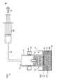
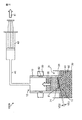
- FIG. 1 is a schematic diagram of a filtration device 100A according to Embodiment 1 of the present invention.
- the filtration device 100 ⁇ / b> A includes a container unit 10 that introduces a liquid 60 containing a biological substance 61, a membrane unit 20 that separates the biological substance 61 from the liquid 60, and a liquid container that holds the liquid 60. 30, a suction unit 40 that sucks the liquid 60, and a moving unit 50 that moves the film unit 20.
- the “biological substance” means a substance derived from a living organism such as a cell (eukaryotic organism), a bacterium (eubacteria), or a virus.
- cells eukaryotes
- examples of cells include eggs, sperm, induced pluripotent stem cells (iPS cells), ES cells, stem cells, mesenchymal stem cells, mononuclear cells, single cells, cell masses, suspension cells, and adhesions.
- sex cells nerve cells, leukocytes, lymphocytes, cells for regenerative medicine, autologous cells, cancer cells, circulating cancer cells (CTC), HL-60, HELA, and fungi.
- bacteria examples include gram positive bacteria, gram negative bacteria, Escherichia coli, and tuberculosis bacteria.
- virus examples include DNA virus, RNA virus, rotavirus, (bird) influenza virus, yellow fever virus, dengue fever virus, encephalitis virus, hemorrhagic fever virus, and immunodeficiency virus.
- filtration device 100A is particularly excellent in separating artificial pluripotent stem cells (iPS cells), ES cells, stem cells, and circulating cancer cells (CTC) in blood.
- the biological substance may be a tissue in which cells are collected or an aggregated cell.
- the container unit 10 has a cylindrical shape, and includes an introduction port 11 for introducing the liquid 60 at one end and a discharge port 12 for discharging the liquid 60 at the other end.
- the container part 10 is arrange
- the introduction port 11 of the container part 10 is located vertically below the discharge port 12.
- a film part 20 is provided at the inlet 11 of the container part 10. Further, the inlet 11 of the container unit 10 is disposed in the liquid 60 held in the liquid container 30.
- the discharge port 12 of the container unit 10 is connected to the suction unit 40 via the tube 41.
- a moving part 50 is attached to the outer wall of the container part 10.
- the container portion 10 is formed of a resin such as acrylic, epoxy, polystyrene, or polycarbonate, glass mainly composed of silicon oxide, or the like.
- the container portion 10 may be formed of a thermoplastic resin such as polypropylene, polystyrene, or polycarbonate resin.
- the material of the container part 10 is preferably a material capable of various sterilizations such as gamma ray irradiation, autoclave, ethylene oxide gas, and the like.
- the container portion 10 has, for example, an outer diameter of 1 mm to 60 mm, an inner diameter of 0.5 mm to 50 mm, and a height of 5 mm to 300 mm within a range smaller than the outer shape.
- the membrane unit 20 is a porous membrane that separates the biological material 61 from the liquid 60.
- the film part 20 is a metal thin film having a plurality of through holes 21.
- the film unit 20 is a circular metal mesh, and has a pair of main surfaces facing each other, and a structure having a plurality of through holes 21 penetrating both main surfaces.
- the main surface on the lower side in the vertical direction is the first main surface VS1
- the main surface located on the upper side in the vertical direction from the first main surface VS1 is the second main surface VS2.
- the upward direction in the vertical direction is defined as the upper side
- the downward direction in the vertical direction is defined as the lower side.
- the second main surface VS2 side is defined as the upper side
- the first main surface VS1 side is defined as the lower side when viewed from the thickness direction of the film part 20.
- the film part 20 is provided in the introduction port 11 of the container part 10.
- the film unit 20 is disposed such that the first main surface VS1 and the second main surface VS2 are perpendicular to the inner wall of the container unit 10. That is, the first main surface VS1 and the second main surface VS2 of the film unit 20 are perpendicular to the direction in which the liquid 60 flows from the introduction port 11 to the discharge port 12 of the container unit 10 (arrow 80 shown in FIG. 1).
- the first main surface VS1 and the second main surface VS2 of the film unit 20 are perpendicular to the direction in which the liquid 60 flows from the introduction port 11 to the discharge port 12 of the container unit 10 (arrow 80 shown in FIG. 1).
- the plurality of through holes 21 are periodically arranged over the first main surface VS1 and the second main surface VS2 of the film unit 20.
- the film part 20 is made of nickel, for example.
- the dimensions of the film part 20 are, for example, a diameter of 6 mm and a thickness of 1.2 ⁇ m.
- the material of the film part 20 may be gold, silver, copper, platinum, iron, nickel, chromium, stainless steel, palladium, titanium, cobalt, and oxides or alloys thereof.
- gold, nickel, stainless steel, and titanium are preferable.
- the material of the film part 20 is nickel, the nickel surface may be plated with gold.
- membrane part 20 is a material which can perform various sterilizations, such as gamma ray irradiation, an autoclave, and ethylene oxide gas.
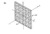
- FIG. 2 shows a schematic configuration diagram of a part of the film part 20 which is a two-dimensional periodic structure.
- the X, Y, and Z directions in FIG. 2 indicate the vertical direction, horizontal direction, and thickness direction of the structure, respectively.
- FIG. 3 shows a view of a part of the film part 20 of FIG. 2 as viewed from the Z direction.
- the film part 20 may be a plate-like structure (lattice-like structure) in which a plurality of through holes 21 are arranged in a matrix at regular intervals.
- the film part 20 is a plate-like structure provided with a plurality of square through holes 21 when viewed from the Z direction which is the main surface side.
- the plurality of through holes 21 are provided at equal intervals in two arrangement directions parallel to each side of the square, that is, in the X direction and the Y direction in FIG.
- the through-hole 21 is not limited to a square, For example, a rectangle, a circle
- the arrangement of the holes is not limited to the square lattice arrangement, and for example, if the arrangement is a square arrangement, a rectangular arrangement in which the intervals in the two arrangement directions are not equal may be used, and a triangular lattice arrangement or a quasi-periodic arrangement may be used.
- the through hole 21 may be provided with a taper.
- the shape and dimensions of the through-hole 21 of the membrane part 20 are appropriately designed according to the size and shape of the biological substance 61 to be filtered.
- the liquid container 30 is a container that holds the liquid 60 containing the biological substance 61.
- the liquid container 30 is a container having an opening larger than the diameter of the container unit 10.
- the inlet 11 of the container unit 10 is arranged in the liquid 60 held in the liquid container 30.
- a gap is formed between the outer wall of the container unit 10 and the inner wall of the liquid container 30. This gap functions as a vent 31 for releasing the pressure applied to the liquid 60 held in the liquid container 30.
- the biological substance 61 is pressurized by a negative pressure.
- the liquid 60 can be opened to the outside by the vent 31. Therefore, the pressure applied to the biological substance 61 in the liquid 60 can be released to the outside.
- the suction unit 40 sucks the liquid 60 held in the liquid container 30 from the introduction port 11 of the container unit 10 to the discharge port 12.
- the suction part 40 is connected to the discharge port 12 of the container part 10 via the tube 41.
- the suction unit 40 is a syringe. As shown in FIG. 1, the suction part 40 sucks the liquid 60 held in the liquid container 30 by pulling the plunger of the syringe (arrow 81 shown in FIG. 1). Thereby, the liquid 60 in the liquid container 30 is sucked up by the suction part 40 from the introduction port 11 of the container part 10 to the discharge port 12 (arrow 80 shown in FIG. 1). In other words, the liquid 60 passes from the first main surface VS1 of the film unit 20 to the second main surface VS2 positioned on the upper side in the vertical direction from the first main surface VS1.
- the moving part 50 moves the film part 20 downward. Specifically, the moving unit 50 moves the film unit 20 toward the liquid 60 held in the liquid container 30. As shown in FIG. 1, in the first embodiment, the moving unit 50 is attached to the outer wall of the container unit 10. The moving part 50 moves the container part 10 vertically downward as the liquid 60 in the liquid container 30 is reduced by the suction part 40 (arrow 82 shown in FIG. 1). Thereby, the moving part 50 can maintain the state which has arrange
- the film part 20 is arranged near the liquid surface of the liquid 60 held in the liquid container 30.
- the vicinity of the liquid surface is a portion where the concentration of the biological substance 61 is low in the liquid container 30.
- the first main surface VS1 of the film unit 20 provided at the inlet 11 is at least liquid. It is a position in contact with 60.
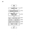
- FIG. 4 is a flowchart of the filtration method according to the first embodiment.
- step ST11 a filtration device 100A is prepared.
- step ST12 the liquid 60 containing the biological substance 61 is introduced into the liquid container 30.
- step ST13 the inlet 11 of the container 10 is placed in the liquid 60.
- the inlet 11 of the container unit 10 is arranged in the liquid 60 held in the liquid container 30.
- the arrangement of the container unit 10 may be performed by the moving unit 50.
- the inlet 11 of the container unit 10 is disposed near the liquid surface of the liquid 60.
- step ST14 the biological material 61 is separated from the liquid 60 by allowing the liquid 60 to pass through the membrane portion 20.
- Step ST14 includes step ST15 in which the liquid 60 in the liquid container 30 is sucked by the suction unit 40.
- step ST15 by pulling the plunger of the suction part 40 (arrow 81 shown in FIG. 1), the liquid 60 held in the liquid container 30 is sucked from the inlet 11 of the container 10 to the outlet 12 ( Arrow 80 shown in FIG.
- the liquid 60 passes from the first main surface VS1 of the film unit 20 to the second main surface VS2 positioned on the upper side in the vertical direction from the first main surface VS1.
- the biological substance 61 cannot pass through the through hole 21 and remains in the liquid container 30.
- Step ST14 includes step ST16 for releasing the pressure applied to the liquid 60 held in the liquid container 30.
- the suction pressure is applied to the liquid 60 in the liquid container 30 by the suction unit 40, the biological material 61 may be deformed. Therefore, the pressure applied to the biological substance 61 in the liquid 60 can be reduced by releasing the pressure applied to the liquid 60 from the vent 31 of the liquid container 30.
- step ST17 for moving the film part 20 downward may be included.
- the suction unit 40 By sucking the liquid 60 by the suction unit 40, the liquid 60 held in the liquid container 30 decreases.
- the container part 10 downward toward the liquid 60 in the liquid container 30 by the moving part 50 By moving the container part 10 downward toward the liquid 60 in the liquid container 30 by the moving part 50, it is possible to maintain the state where the inlet 11 of the container part 10 is arranged near the liquid surface of the liquid 60.
- the biological material 61 is separated from the liquid 60 by steps ST11 to ST16.
- the liquid 60 that has passed through the membrane unit 20 can also be recovered.
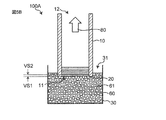
- FIGS. 5A to 5D show the operation of the filtration device 100A.
- 5A to 5D omit the suction unit 40 and the moving unit 50 in order to simplify the description.
- the inlet 11 of the container 10 is placed in the liquid 60 held in the liquid container 30 before the filtration is started.
- the film unit 20 is disposed near the liquid surface of the liquid 60.
- the liquid 60 is sucked from the inlet 11 of the container 10 toward the outlet 12 by the suction part 40 (arrow 80 shown in FIG. 5B).
- the liquid 60 in the liquid container 30 passes from the first main surface VS1 of the film unit 20 to the second main surface VS2.
- the biological substance 61 cannot be passed through the through hole 21 and is captured by the membrane part 20. Therefore, the biological material 61 starts to collect on the first main surface VS1 of the film unit 20.
- the biological substance 61 when the liquid 60 is continuously sucked in the direction 80, the biological substance 61 further gathers on the first main surface VS1 of the film unit 20 to form the cake layer A1. As the filtration time increases, the biological material 61 further gathers in the membrane part 20, so that the cake layer A1 becomes thicker.
- the biological material 61 repeats the assembly and separation in the lower layer A2 of the cake layer A1.
- the increase in the thickness of the cake layer A1 is stopped and clogging is suppressed, so that the filtration does not stop. That is, in the filtration device 100A, the cake layer A1 does not become thick enough to stop filtration, so that the separation of the biological material 61 can be continued.
- the through-hole 21 of the film part 20 is blocked by the cake layer A1, so that pressure resistance is generated.
- the suction force by the suction part 40 becomes small.
- a force in the direction of gravity due to its own weight is applied to the biological substance 61 in the liquid 60.
- the biological material 61 collects in the cake layer A1.
- the biological substance 61 is detached from the cake layer A1.
- the collection and separation of the biological material 61 are repeated by the balance between the suction force of the suction unit 40 and the force in the direction of gravity.
- the biological substance 61 can be detached from the cake layer A1 by vibration of the filtration device 100A.
- the biological material 61 may be separated from the cake layer A1 by vibration generated by shaking the filtering device 100A up and down and / or left and right.
- the filtration device of the reference example includes a container part 110 having an introduction port 111 for introducing the liquid 60 and a discharge port 112 for discharging the liquid 60, and a membrane part 120 having a plurality of through holes.
- the introduction port 111 is positioned above the discharge port 112 in the vertical direction, and the film unit 120 is provided in the discharge port 112 of the container unit 110.
- the liquid 60 is allowed to pass from the second main surface VS12 of the membrane unit 120 to the first main surface VS11 positioned vertically below the second main surface VS12.
- the filtering device 100A allows the liquid 60 to pass through the membrane portion 20 from the lower side in the vertical direction to the upper side, whereas the filtering device in the reference example is from the upper side in the vertical direction toward the lower side.
- the liquid 60 is passed through the membrane part 120.
- the liquid 60 is passed through the membrane part 120 by sucking the liquid 60 with a suction pump installed below.
- the liquid 60 containing the biological substance 61 flows downward. That is, in the filtration device of the reference example, the liquid 60 flows from the inlet 111 of the container 110 toward the outlet 112 (arrow 80r shown in FIG. 6A). For this reason, the liquid 60 flowing in the container part 110 passes from the second principal surface VS12 of the film part 120 to the first principal surface VS11 located on the lower side in the vertical direction than the second principal surface VS12. When the liquid 60 passes through the membrane part 120, the biological substance 61 is captured by the membrane part 120. Therefore, the biological material 61 is deposited on the second main surface VS12 of the film unit 120.
- the cake layer A3 is formed on the second main surface VS12 of the film part 120 due to the deposition of the biological material 61.
- the thickness of the cake layer A3 gradually increases as the capture of the biological substance 61 by the membrane part 120 increases.
- the filtration gradually shifts from the second main surface VS12 of the film part 120 to the upper layer A4 of the cake layer A3. That is, the separation of the biological substance 61 is not performed in the membrane part 120 but in the upper layer A4 of the cake layer A3.
- the biological substance 61 captured by the film unit 120 is deposited on the second main surface VS12 of the film unit 120. For this reason, since the cake layer A3 gradually increases as the amount of the biological substance 61 captured by the membrane portion 120 increases, clogging occurs in the upper layer A4 of the cake layer A3. As a result, in the filtering device of the reference example, the filtration is stopped due to clogging due to the deposition of the biological substance 61 captured by the membrane part 120, and the biological substance 61 cannot be separated from the liquid 60.
- the filtering device 100A can continue to separate the biological material 61 from the liquid 60 by suppressing clogging as compared with the filtering device of the reference example.
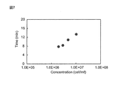
- FIG. 7 shows the measurement result of the concentration of the biological substance 61 when the liquid 60 is filtered by the filtering device 100A.
- the vertical axis indicates the time (min) required for filtration
- the horizontal axis indicates the concentration (cell / ml) of the biological substance 61.
- FIG. 8 shows a measurement result of the concentration of the biological substance 61 when the liquid 60 is filtered by the filtration device of the reference example.
- the vertical axis indicates the time (min) required for filtration, and the horizontal axis indicates the concentration (cell / ml) of the biological substance 61.
- the concentration of the biological substance 61 means the number of biological substances 61 per ml.
- HL-60 which is a nucleated cell was used as a biological substance, and physiological saline was used as a solution.
- the measurement conditions for filtration in FIGS. 7 and 8 will be described.
- the concentration of the liquid 60 containing the biological substance 61 captured by the membrane part was measured. . Further, the time required for filtering the liquid 60 was also measured.
- Diameter of membrane part ⁇ 6mm
- Diameter of through hole 2.5 ⁇ m
- Hole spacing between through holes 3.6 ⁇ m
- Syringe suction speed at the start of suction 0.2 ml / min
- Liquid volume 1.0ml
- Liquid extraction volume 0.8ml
- the upper limit concentration of the biological substance 61 in the liquid 60 is about 1.0 ⁇ . 10 7 cells / ml. Moreover, it took about 13 minutes to filter the liquid 60 and extract the liquid amount of 80%.
- the upper limit concentration of the biological substance 61 in the liquid 60 is about 2.0. ⁇ 10 6 cells / ml. Moreover, the time from filtering the liquid 60 to extracting the 80% liquid volume was about 20 min. In the filtration device of the reference example, an attempt was made to filter the liquid 60 having a biological substance 61 concentration of about 1.0 ⁇ 10 7 cells / ml, but the filtration did not proceed even after 1 hour.
- the filtering device 100A can filter the liquid 60 having a high concentration in a shorter time than the filtering device of the reference example. That is, the filtering device 100A has a higher filtering concentration limit of the biological material 61 than the filtering device of the reference example, and can filter the liquid 60 in a shorter time.
- FIG. 9 shows the measurement result of the leakage rate of the biological material 61 when the liquid 60 is filtered by the filtration device 100A.
- the vertical axis indicates the leakage rate (%) of the biological substance 61
- the horizontal axis indicates the concentration (cell / ml) of the biological substance 61.
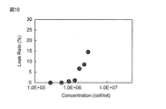
- FIG. 10 shows the measurement result of the leakage rate of the biological material 61 when the liquid 60 is filtered by the filtration device of the reference example.
- Leakage rate means the proportion of biological material that has passed through the membrane.
- the leak rate is calculated by (number of biological substances passing through the membrane part) / (number of biological substances contained in the liquid before filtration) ⁇ 100.
- the upper limit of the leakage rate of the biological material 61 was about 7%. That is, the recovery rate of the biological material 61 in the filtration device 100A was about 93%.
- the upper limit of the leakage rate of the biological material 61 is about 15%. It was. That is, the recovery rate of the biological material 61 in the filtration device 100A was about 85%.
- the filtering device 100A can achieve a higher recovery rate than the filtering device of the reference example. More specifically, in the filtration device of the reference example, the pressure in the vicinity of the membrane part 120 increases, and the biological material having high deformability originally deforms and may pass through the through hole of the membrane part 120. . On the other hand, in the case of the filtering device 100A, the pressure in the vicinity of the membrane unit 20 is relatively low, and the filtration operation can be performed while keeping the deformation of the biological material small, so that it passes through the through-hole of the membrane unit 20. Few. Therefore, the filtering device 100A can recover the biological material 61 at a higher recovery rate than the filtering device of the reference example.
- the following effects can be obtained.
- the membrane unit 20 allows the liquid 60 containing the biological substance 61 to pass from the first main surface VS1 to the second main surface VS2 positioned on the upper side in the vertical direction from the first main surface VS1.
- the liquid 60 is passed through the membrane portion 20 from the lower side in the vertical direction toward the upper side to perform filtration.
- the filtering device 100A As a result, in the filtering device 100A, the liquid 60 having a higher concentration is filtered in a shorter time as compared with the filtering device of the reference example that allows the liquid 60 to pass through the membrane portion 120 from the upper side to the lower side in the vertical direction. Can do. Further, in the filtration device 100A, the recovery rate of the biological material 61 can be increased as compared with the filtration device of the reference example.
- the filtering device 100A separates the biological material 61 and the liquid 60, but is not limited to this.
- the filtration device 100A may filter a foreign substance having a size larger than that of the biological substance 61 contained in the liquid 60 by allowing the solution in the liquid 60 and the biological substance 61 to pass therethrough. Or 100A of filtration apparatuses may filter and classify
- the membrane unit 20 uses a metal thin film as a porous membrane. With such a configuration, it is possible to prevent the membrane portion 20 from being damaged by applying a force to the membrane portion 20. Further, even when the liquid 60 passes through the membrane part 20, since the through-hole 21 of the membrane part 20 is not easily deformed, the biological substance 61 is prevented from passing through the membrane part 20 due to the deformation of the through-hole 21. can do. Furthermore, damage to the film part 20 due to the liquid 60 can also be suppressed.
- a vent 31 for releasing the pressure applied to the liquid 60 is formed by forming a gap between the outer wall of the container 10 and the inner wall of the liquid container 30.
- the liquid 60 in the liquid container 30 can be opened to the outside. Therefore, the pressure applied to the liquid 60 by suction can be released from the vent 31, and the pressure applied to the biological substance 61 in the liquid 60 can be reduced.
- the gas passing through the vent 31 is preferably sterilized. This is to prevent the mixing of biological materials other than the biological material 61 originally contained in the liquid 60.
- the suction part 40 sucks the liquid 60 held in the liquid container 30, thereby allowing the liquid 60 to pass from the first main surface VS1 to the second main surface VS2 of the film part 20.
- the liquid 60 in the liquid container 30 can be passed through the membrane unit 20 and the biological material 61 can be separated from the liquid 60.
- the suction can be performed in a shorter time by sucking the liquid 60 by the suction unit 40.
- the moving unit 50 moves the container unit 10 toward the liquid 60 as the liquid 60 in the liquid container 30 decreases.
- the moving unit 50 moves the container unit 10 toward the liquid 60 as the liquid 60 in the liquid container 30 decreases.
- the container part 10 demonstrated the structure arrange
- the container part 10 may be arrange
- the filtering device 100A may be arranged in an oblique direction to perform filtration.
- the container part 10 demonstrated the structure which is a cylindrical body, it is not limited to this.
- the container unit 10 may be configured to introduce the liquid 60 therein, pass through the film unit 20 and discharge the liquid 60, and may have a polygonal column shape such as a square column.
- the membrane unit 20 may be a porous membrane, and may be a membrane, a filter paper, a nonwoven fabric, or the like, for example.
- membrane part 20 is provided in the inlet 11 of the container part 10, it is not limited to this.
- the film part 20 is not limited as long as the liquid 60 passes from the first main surface VS1 to the second main surface VS2 positioned on the upper side in the vertical direction from the first main surface VS1.
- the film part 20 may be provided between the inlet 11 and the outlet 12 of the container part 10.
- the film part 20 may be provided in the discharge port 12.
- a plurality of film parts 20 may be provided between the inlet 11 and the outlet 12 of the container part 10.
- the first film part 20 may be provided at the inlet 11 of the container part 10 and the second film part 20 may be provided above the first film part 20 in the vertical direction.
- the recovery rate can be improved by configuring the multistage filtration device 100A using the plurality of membrane portions 20.
- the size of the through hole of the first film unit 20 and the size of the through hole of the second film unit 20 to be different, cells having two different sizes can be filtered. Thereby, a cell can be classified.
- FIG. 11 shows a filtering device 100B according to a modification of the first embodiment.
- the membrane unit 20 may be arranged in an oblique direction with a predetermined angle ⁇ with respect to the vertical direction.
- the film part 20 may be disposed to be inclined with respect to the horizontal direction.
- membrane part 20 may be arrange
- the allowable amount of the cake layer formed by the film part 20 is increased, so that the clogging of the film part 20 by the biological substance 61 can be further suppressed. That is, by disposing the membrane part 20 at an angle, the area where the membrane part 20 is in contact with the liquid 60 can be increased, and the filtration efficiency is improved.
- the liquid container 30 forms the air vent 31 by providing a clearance between the outer wall of the container part 10 and the inner wall of the liquid container 30, it is not limited to this.
- the vent 31 may be formed by providing a hole in the side wall of the liquid container 30.
- a ventilation filter may be provided instead of the ventilation port 31.
- the liquid container 30 demonstrated the structure provided with the vent 31 which releases the pressure concerning a liquid, it is not limited to this.
- the liquid container 30 may be in a state where the vent 31 is not provided and the liquid 60 is not opened to the outside.
- the present invention is not limited thereto.
- the liquid 60 may be passed from the first main surface VS1 to the second main surface VS2 of the film unit 20 by pressurizing the liquid 60 in the liquid container 30 from a position corresponding to the vent 31.
- the liquid 60 may be passed from the first main surface VS1 to the second main surface VS2 of the membrane unit 20 by applying a centrifugal force to the liquid 60 in the liquid container 30 using a centrifuge.
- the suction unit 40 may be a pump or the like and may be any device that can suck the liquid 60.
- the liquid container 30, the suction unit 40, and the moving unit 50 are not essential components, and these elements may be omitted or replaced with other elements.
- the filtering device 100A has been described with respect to the example used for filtering the biological substance 61, but is not limited thereto.
- the filtration device 100A may be used to replace the medium in the culture container in which the cells are cultured. Even when the medium is exchanged during the cell culture using the filtration device 100A, clogging of the membrane part 20 by the cells can be suppressed.
- the filter device 100A when exchanging the culture medium of adhesive cells, the adhesive cells themselves are attracted to the inner wall of the culture container, so that it is difficult to contact the membrane portion 20. For this reason, according to the filter device 100A, compared with the filter device of the reference example, the efficiency of exchanging the culture medium of the adhesive cells can be improved.
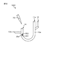
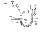
- FIG. 12 shows a schematic configuration of a filtration device 100C according to the second embodiment.
- differences from the first embodiment will be mainly described.
- the same or similar components as those in the first embodiment will be described with the same or similar reference numerals.
- descriptions overlapping with those in the first embodiment are omitted.
- the first introduction port 11a for introducing the liquid 60 is more than the discharge port 12a for discharging the liquid 60, compared to the filtering device 100A of the first embodiment.
- the container portion 10a has a curved shape so as to be positioned on the upper side in the vertical direction.
- the filtration device 100C does not include the liquid container 30, the suction unit 40, and the moving unit 50.
- the filtration device 100 ⁇ / b> C includes a container part 10 a for introducing a liquid 60 containing a biological substance 61 and a membrane part 20 a for separating the biological substance 61 from the liquid 60.
- the container part 10a has a first introduction port 11a for introducing the liquid 60 and a discharge port 12a for discharging the liquid 60, and is curved so that the first introduction port 11a is positioned above the discharge port 12a in the vertical direction. It has a shape.
- the container portion 10a has a U-shaped tube shape. Specifically, the bottoms of the two tubes are integrally formed by connecting them with a U-curved tube.
- the container section 10a has a first introduction port 11a for introducing the liquid 60 on one end side and a second introduction port 13 for introducing cleaning water, and a discharge port for discharging the liquid 60 on the other end side. 12a and an insertion port 14 into which a pipette 70 is inserted.
- the 1st inlet 11a is provided in the end of the container part 10a.
- the 2nd inlet 13 is provided in the pipe
- the discharge port 12a is provided in a pipe extending in the horizontal direction provided on the side wall on the other end side of the container portion 10a.
- the insertion port 14 is provided at the other end of the container portion 10a.
- the first introduction port 11a and the second introduction port 13 on one end side of the container part 10a are provided at a position vertically above the discharge port 12a on the other end side.
- the film part 20a is a metallic thin film having a plurality of through holes 21, and is disposed between the first inlet 11a and the outlet 12a.
- the membrane portion 20a is disposed at the bottom of the tube on the other end side of the container portion 10a, and is connected to a connection portion between the tube on the other end side and a tube curved in a U shape.
- the first main surface VS1 of the film unit 20a is located on the lower side in the vertical direction than the second main surface VS2.
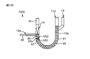
- FIGS. 13A to 13D show the filtration operation in the filtration device 100C.
- FIG. 13D shows an operation of cleaning the biological substance 61 in the filtration device 100C.
- the liquid 60 containing the biological substance 61 is introduced from the first inlet 11a into the container 10a (arrow 83 shown in FIG. 13A).
- the liquid 60 introduced into the container portion 10a flows toward the discharge port 12a due to its own weight (arrow 85 shown in FIG. 13A).
- the first introduction on the one end side is performed.
- the liquid 60 introduced from the mouth 11a flows in the direction of gravity by its own weight.
- the liquid 60 that flows in the direction of gravity flows through the curved portion in the container portion 10a while maintaining the momentum, and is discharged from the discharge port 12a.
- the liquid 60 flows from the first main surface VS1 of the film part 20a to the second main surface VS2 positioned on the upper side in the vertical direction from the first main surface VS1 (arrow 84 shown in FIG. 13A). For this reason, the biological material 61 can be captured in the first main surface VS1 of the film part 20a.
- the pipette 70 is inserted from the insertion port.
- the liquid 60 is injected from the pipette 70 inserted into the insertion port 14 toward the membrane portion 20a (arrow 86 shown in FIG. 13C).
- the liquid 60 from the pipette 70 flows from the second main surface VS2 of the film unit 20 toward the first main surface VS1. For this reason, the liquid 60 that has passed through the film part 20a is pushed down from the second main surface VS2 of the film part 20a toward the first main surface VS1 (arrow 87 shown in FIG. 13C).
- the biological substance 61 captured by the first main surface VS1 of the film part 20a can be removed from the first main surface VS1 to remove the cake layer.
- the filtration device 100C can continue the filtration by removing the pipette 70 from the insertion port 14 and introducing the liquid 60 containing the biological substance 61 from the first introduction port 11a.
- the filtering device 100C filters the liquid 60 containing the biological material 61 by performing the operations shown in FIGS. 13A to 13C.
- the filtration device 100C can also concentrate the liquid 60 by repeatedly performing the operations shown in FIGS. 13A to 13C.
- the filtration device 100C can wash the filtered biological material 61 by introducing wash water from the second inlet 13 as shown in FIG. 13D.
- the introduction of the liquid 60 from the first introduction port 11a is stopped, and washing water is introduced from the second introduction port 13 (arrow 88 shown in FIG. 13D).
- the washing water introduced from the second introduction port 13 passes through the inside of the container part 10 and is discharged from the discharge port 12a (arrow 85 shown in FIG. 13D).
- the pipette 70 is inserted into the insertion port 14, and washing water is injected from the pipette 70 toward the membrane part 20a (arrow 89 shown in FIG. 13D). . After the clogging is eliminated, the pipette 70 is taken out from the insertion port 14 and cleaning water is introduced from the second introduction port 13.
- the filtration device 100C can wash the filtered biological material 61 by performing the operation shown in FIG. 13D.
- the container portion 10a has a U-shaped tube shape in which the bottoms of two tubes are connected by a U-shaped curved tube.
- transduces the liquid 60 provided in the one end side is located in the perpendicular direction upper side rather than the discharge port 12a which discharges
- the film part 20a is arrange
- the liquid 60 is allowed to pass through the surface VS2. With such a configuration, the liquid 60 is introduced into the first introduction port 11a by its own weight, so that the liquid 60 passes from the first main surface VS1 to the second main surface VS2 of the film portion 20a to the VS2. 61 can be separated.
- an insertion port 14 for inserting the pipette 70 is provided on the other end side of the container portion 10a.
- the pipette 70 is inserted into the insertion port 14, and the liquid is directed from the pipette 70 toward the first main surface VS1 from the second main surface VS2 of the film portion 20a.
- 60 can be injected.
- the liquid 60 injected from the pipette 70 is formed on the first main surface VS1 of the film part 20a by pushing back the biological material 61 blocking the through hole 21 of the film part 20a to the first introduction port 11a side.
- the cake layer can be removed.
- the pressure due to the injection of the liquid 60 from the pipette 70 does not become so great as to cause deformation of the biological material 61. Therefore, in the filtering device 100C, the clogging of the membrane portion 20a can be eliminated without damaging the biological material 61 using the pipette 70. Further, by repeatedly injecting (pipetting) the liquid 60 with the pipette 70, it is possible to maintain a state in which clogging does not occur in the film part 20a.
- a second introduction port 13 for introducing cleaning water is provided on one end side of the container portion 10a.
- Embodiment 2 although the structure which provided the 2nd inlet 13 which introduce
- the structure which introduces washing water from the 1st inlet 11a, without providing the 2nd inlet 13 may be sufficient.
- the structure which inserts the pipette 70 in the discharge port 12a, without providing the insertion port 14 may be sufficient. With such a configuration, the liquid 60 can be filtered with a simple configuration.
- Embodiment 2 although the structure which introduce
- a liquid (substitution liquid) different from the liquid 60 may be introduced from the second introduction port 13 and the liquid 60 in the container unit 10 may be replaced with another liquid.
- the pipette 70 inserted into the insertion port 14 is configured to inject the liquid 60 toward the film part 20a in order to remove the cake layer formed on the first main surface VS1 of the film part 20a.
- the pipette 70 may be used for stirring the liquid 60 in the container part 10a.
- the pipette 70 may introduce a replacement liquid toward the film part 20a and replace the liquid 60 in the container part 10 with another liquid.
- the pipette 70 may be pipetted in a closed system that does not allow the injection pressure of the liquid 60 from the pipette 70 to escape to the outside of the container portion 10a by being inserted so as to close the insertion port 14.
- the container portion 10a has been described with respect to a U-shaped tube, but is not limited thereto.
- the curved U-shaped portion of the container portion 10a may be provided with a three-way branch for recovery using a rubber tube in order to provide flexibility and a difference in height between the left and right tubes. With such a configuration, the biological material 61 can be easily recovered.
- Embodiment 2 although the structure which performs filtration by the dead weight of the liquid 60 introduced from the 1st inlet 11a was demonstrated, it is not limited to this.
- filtration may be performed by pressurizing the liquid 60 from the first introduction port 11a. With such a configuration, filtration can be performed in a short time.
- the pipette 70 is not an essential configuration.
- the pipette 70 may be omitted or may be replaced with other elements such as gas pressurization.
- FIG. 14 shows a schematic configuration of the filtration device 100D of the third embodiment.
- differences from the first embodiment will be mainly described.
- the same or similar components as those in the first embodiment will be described with the same or similar reference numerals.
- descriptions overlapping with those in the first embodiment are omitted.
- the filtering device 100D of the third embodiment has a configuration in which the container portion 10b can move on the inner wall of the liquid container 30b, compared to the filtering device 100A of the first embodiment. Different. Further, the filtering device 100D is different from the filtering device 100A in that the membrane portion 20b is provided obliquely with respect to the first side wall 10ba of the container portion 10b. The filtration device 100D does not include the suction unit 40.
- the filtration device 100D is disposed between a container portion 10b having an introduction port 11b for introducing a liquid 60 containing a biological substance 61 and a discharge port 12b for discharging the liquid 60, and the introduction port 11b and the discharge port 12b.
- a film part 20b having a plurality of through holes 21 and a liquid container 30b for holding the liquid 60 are provided.
- the container portion 10b is attached to the inside of the liquid container 30b and can move inside the liquid container 30b.
- the filtration device 100D moves the container part 10b downward, thereby causing the liquid 60 in the liquid container 30b to be positioned from the first main surface VS1 of the film part 20b to the upper side in the vertical direction from the first main surface VS1. It passes through VS2.
- the container portion 10b includes a first side wall 10ba disposed in the liquid container 30, a second side wall 10bb disposed outside the liquid container 30, a first side wall 10ba, and a second side wall 10bb.
- a third side wall 10bc to be connected is provided.
- the first side wall 10ba is an inner cylinder that is arranged in the liquid container 30 and is movable toward the liquid 60 held in the liquid container 30b.
- An inlet 11b through which the liquid 60 in the liquid container 30b is introduced is provided at one end of the first side wall 10ba, and an outlet 12b through which the liquid 60 is discharged is provided at the other end.
- the introduction port 11b is located on the lower side in the vertical direction than the discharge port 12b.
- a film portion 20b having a plurality of through holes 21 is disposed in the introduction port 11b.
- the outer peripheral part of the film part 20b is designed with a material and a dimension capable of sliding on the inner wall of the liquid container 30b. That is, the outer peripheral portion of the membrane portion 20b is designed so that the biological substance 61 does not pass between the outer peripheral portion of the membrane portion 20b and the liquid container 30b, and the membrane portion 20b faces the liquid 60 in the liquid container 30b. It is designed to be able to move.
- the second side wall 10bb is an outer cylinder disposed outside the liquid container 30 and slidable with respect to the outer wall of the liquid container 30.
- the second side wall 10bb includes a first moving unit 50a on the inner wall.
- the first moving part 50 a is engaged with the second moving part 50 b provided on the outer wall of the liquid container 30, and moves the container part 10 b toward the liquid 60.
- the first moving part 50a is formed with an internal thread and is screwed with the second moving part 50b formed with an external thread.
- the third side wall 10bc is a ring-shaped member that connects the first side wall 10ba and the second side wall 10bb so as to form a space in which the side wall of the liquid container 30 enters between the first side wall 10ba and the second side wall 10bb. is there. Specifically, the third side wall 10bc connects the end of the first side wall 10ba on the discharge port 12b side and the upper end of the second side wall 10bb.
- the first side wall 10ba, the second side wall 10bb, and the third side wall 10bc may be integrally formed.
- the film part 20b is disposed in the introduction port 11b of the first side wall 10ba, and is disposed in an oblique direction with a predetermined angle ⁇ with respect to the inner wall of the first side wall 10ba. In other words, the film part 20b is arranged to be inclined with respect to the horizontal direction.
- the diameter of the through-hole 21 of the membrane part 20b is designed to a size that allows the liquid 60 to pass through without passing the biological substance 61 to be filtered.
- the liquid container 30 b is a cylindrical container that holds the liquid 60 containing the biological substance 61.
- the first side wall 10ba of the container portion 10b is slidably disposed on the inner wall of the liquid container 30b.
- the first side wall 10ba is movable downward toward the liquid 60 held in the liquid container 30b.
- the outer wall of the liquid container 30b includes a second moving unit 50b.
- the second moving part 50b engages with the first moving part 50a provided on the second side wall 10bb of the container part 10b.
- the second moving part 50b is formed with a male screw as described above, and is screwed with the first moving part 50a formed with a female screw provided on the second side wall 10bb of the container part 10b.
- FIGS. 15A and 15B show the filtering operation in the filtering device 100D.
- the container 10b is removed from the liquid container 30b, and the liquid 60 containing the biological substance 61 is introduced into the liquid container 30.
- the container portion 10b is attached to the liquid container 30b.
- the first side wall 10ba of the container part 10b is arranged inside the liquid container 30b, and the first moving part 50a of the second side wall 10bb of the container part 10b and the second moving part 50b of the liquid container 30b are engaged.
- the container part 10b moves vertically downward toward the liquid 60 held in the liquid container 30b (arrow 91 shown in FIG. 15B). That is, the film part 20 b arranged at the introduction port 11 b of the container part 10 b moves vertically downward toward the liquid 60.
- the liquid 60 in the liquid container 30b passes from the first main surface VS1 of the film part 20b to the second main surface VS2 (arrow 92 shown in FIG. 15B).
- the film part 20b provided obliquely with respect to the inner wall of the first side wall 10ba of the container part 10b moves toward the liquid 60 while rotating around the axis of the container part 10b. For this reason, the biological substance 61 adhering to the 1st main surface VS1 of the film
- membrane part 20b can be peeled by the vibration by rotation.
- the liquid 60 is discharged from the discharge port 12b of the container portion 10b by turning the filtration device 100D upside down. Thereafter, a new liquid or a replacement liquid may be introduced. Alternatively, the liquid 60 may be discharged from the discharge port 12b by a method such as suction.
- the membrane part 20b is moved toward the liquid 60 held in the liquid container 30b by moving the container part 10b downward. Therefore, the liquid 60 in the liquid container 30b passes through the second main surface VS2 located on the upper side in the vertical direction from the first main surface VS1 of the film part 20b. With such a configuration, the biological substance 61 can be easily separated from the liquid 60 by gradually moving the film part 20 b toward the liquid 60.
- the liquid 60 extracted into the container portion 10b can be discharged from the discharge port 12b by turning the filtration device 100D upside down after the filtration. Further, after discharging the liquid 60, by introducing a new liquid or a replacement liquid, it is possible to easily perform cleaning or liquid replacement. Thus, in the filtering device 100D, pipetting by a pipette or the like is not necessary, and user convenience is improved.
- the membrane part 20b is disposed obliquely with respect to the inner wall of the first side wall 10ba of the container part 10b. Therefore, when the film part 20b is moved toward the liquid 60 in the liquid container 30b, it is possible to suppress the biological substance 61 from adhering to the first main surface VS1 of the film part 20b. Thereby, clogging due to the adhesion of the biological substance 61 in the film part 20b can be suppressed.
- the membrane portion 20b is moving downward while rotating. For this reason, the biological substance 61 adhering to the 1st main surface VS1 of the film
- membrane part 20b demonstrated the structure provided diagonally with respect to the inner wall of 1st side wall 10ba of the container part 10b, it is not limited to this.
- a part of the film part 20b may be provided obliquely with respect to the inner wall of the first side wall 10ba.
- the film part 20b may be provided perpendicular to the inner wall of the first side wall 10ba.
- the configuration including the first moving part 50a provided on the inner wall of the second side wall 10bb of the container part 10b and the second moving part 50b provided on the outer wall of the liquid container 30 has been described. It is not limited to this.
- the filtering device 100D is not provided with the first moving unit 50a and the second moving unit 50b, and is directed toward the liquid 60 held in the liquid container 30 by the weight of the film unit 20b and the container unit 10b. May be moved.
- the filtering device 100D may move the film part 20b toward the liquid 60 by pushing the third side wall 10bc downward.
- the second liquid is introduced inside the container portion 10b so that the liquid 60 can easily pass through the through hole 21 of the membrane portion 20b with the container portion 10b attached in the liquid container 30b.
- filtration may be started. That is, the filtration device 100D may start the filtration in a state where the second liquid is held on the second main surface VS2 of the film part 20b.
- a stirring blade for stirring the liquid 60 may be provided inside the liquid container 30b.
- the stirring blade can suppress the biological substance 61 in the liquid 60 from adhering to the film part 20b.
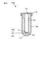
- FIG. 16 shows a schematic configuration of a filtration device 100E according to the fourth embodiment.
- differences from the first embodiment will be mainly described.
- the same or similar components as those in the first embodiment will be described with the same or similar reference numerals.
- descriptions overlapping with those in the first embodiment are omitted.
- the filtration device 100E according to the fourth embodiment has a liquid 60 by applying a centrifugal force from the discharge port 12c of the container portion 10c to the introduction port 11c, as compared with the filtration device 100A according to the first embodiment.
- the difference is that it has a configuration capable of separating the biological material 61 from the biological material.
- the filtration device 100E does not include the suction unit 40 and the moving unit 50.
- the filtration device 100E is disposed between a container portion 10c having an introduction port 11c for introducing the liquid 60 containing the biological substance 61 and a discharge port 12c for discharging the liquid 60, and the introduction port 11c and the discharge port 12c.
- a film part 20 c having a plurality of through holes 21 and a liquid container 30 c for holding the liquid 60 are provided.
- the container part 10c is attached inside the liquid container 30c.
- the filtering device 100E applies the centrifugal force in the direction from the discharge port 12c to the introduction port 11c of the container part 10c, thereby causing the liquid 60 in the liquid container 30c to flow from the first main surface VS1 to the first main surface VS1 of the film unit 20c.
- the container portion 10c is provided with a deaeration hole.
- the container part 10c is arrange
- a lid 32 that covers the opening of the liquid container 30c is attached.
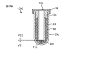
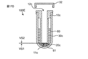
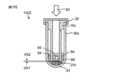
- FIGS. 17A to 17F show the filtration operation in the filtration device 100E.
- the container portion 10c is removed from the liquid container 30c, and the liquid 60 containing the biological substance 61 is introduced into the liquid container 30c.
- the container portion 10c is mounted in the liquid container 30c holding the liquid 60.
- the lid 32 is attached in a state where the container portion 10c is held inside the liquid container 30c. That is, the inlet 11c of the container part 10c is disposed in the liquid 60 in the liquid container 30c.
- the lid 32 is attached by, for example, screwing a female screw provided inside the lid 32 and a male screw provided on the outer wall of the liquid container 30c.
- the liquid 60 held in the liquid container 30c is pushed up between the outer wall of the container 10c and the inner wall of the liquid container 30c by attaching the container 10c inside the liquid container 30c.
- the filtration device 100E is set in the centrifuge.
- the centrifuge is stopped and the lid 32 is removed from the liquid container 30c.
- the liquid 60 that has passed through the membrane portion 20c is discharged.
- the liquid 60 is discharged by turning the liquid container 30c upside down with the container portion 10c attached to the liquid container 30c.
- the biological substance 61 accumulated at the bottom of the liquid container 30c cannot pass through the through hole 21 of the membrane part 20c. Therefore, the liquid 60 that does not contain the biological substance 61 is discharged from the discharge port 12c.
- a lid 32 is attached to the liquid container 30c, and centrifugal force from the outlet 12c to the inlet 11c is applied to the filtration device 100E by a centrifuge (arrow 93 shown in FIG. 17E).
- the liquid 60 between the outer wall of the container portion 10c and the inner wall of the liquid container 30c flows toward the bottom of the liquid container 30c, as in the operation shown in FIG. 17C (see FIG. 17E).
- Arrow 94 the liquid 60 not containing the biological substance 61 flows from the bottom of the liquid container 30c to the introduction port 11c of the container 10c and passes through the membrane 20c (arrow 95 shown in FIG. 17E).
- membrane part 20c become the same.
- the centrifuge is stopped and the lid 32 is removed from the liquid container 30c. Thereafter, similarly to the operation shown in FIG. 17D, the liquid 60 that has passed through the film part 20c and accumulated inside the container part 10c is discharged from the discharge port 12c.
- the filtration device 100E separates the biological substance 61 from the liquid 60 by using the centrifugal force by performing the operations shown in FIGS. 17A to 17F. Furthermore, the filtration device 100E can concentrate the biological material 61 by repeating the operations shown in FIGS. 17A to 17F. Moreover, the filtration apparatus 100E can also wash
- the liquid 60 is passed through the membrane portion 20c in the direction opposite to the direction in which the centrifugal force is applied. Specifically, when a centrifugal force is applied to the filtering device 100C, the height of the liquid surface between the outer wall of the container part 10c and the inner wall of the liquid container 30c and the liquid 60 passing through the film part 20c. The liquid 60 is allowed to pass vertically upward through the film part 20c using the difference in height from the liquid level. With such a configuration, the biological substance 61 can be separated from the liquid 60 without clogging the membrane part 20 c with the biological substance 61. Further, in the filtration device 100E, the biological material 61 can be easily concentrated by repeatedly performing filtration by centrifugation.
- the filtering device 100E when the liquid 60 that has passed through the membrane portion 20c is taken out, for example, the liquid 60 can be easily discharged by turning the filtering device 100E upside down. Thus, in the filtering device 100E, pipetting by the operator is unnecessary, and the liquid 60 can be discharged without requiring a special skill from the operator. As a result, in the filtration device 100E, the recovery rate of the biological material 61 is not reduced by pipetting.
- the biological substance 61 can be washed by introducing washing water and performing centrifugation. Further, in the filtration device 100E, after the biological material 61 is separated, the liquid can be easily replaced by introducing a replacement liquid.
- Embodiment 4 although the structure provided with the lid
- the lid 32 is not an essential component, and may be omitted or replaced with another element.
- the present invention relates to a filtration device and a filtration method, and is excellent in terms of filtering a high concentration liquid and filtering in a short time. For example, it is useful in fields such as chemical analysis, charge / pharmaceuticals, clinical examination, public health management, and environmental measurement.
Landscapes
- Chemical & Material Sciences (AREA)
- Chemical Kinetics & Catalysis (AREA)
- Filtering Materials (AREA)
- Filtration Of Liquid (AREA)
- Apparatus Associated With Microorganisms And Enzymes (AREA)
- Separation Using Semi-Permeable Membranes (AREA)
Abstract
生物由来物質による目詰まりを抑制し、液体から生物由来物質を分離することができる濾過装置及び濾過方法を提供する。本発明の濾過装置は、生物由来物質を含む液体を導入する導入口と液体を排出する排出口とを有する容器部と、容器部の導入口と排出口との間に設けられ、複数の貫通孔を有する膜部と、を備える。膜部は、第1主面と、第1主面よりも上側に位置する第2主面とを有し、膜部の第1主面から第2主面へ液体を通過させることによって、生物由来物質を液体から分離する。
Description
本発明は、液体中の生物由来物質を濾過する濾過装置及び濾過方法に関する。
近年、液体中の生物由来物質を濾過する細胞捕捉システムが開示されている(例えば、特許文献1参照。)。特許文献1に開示された細胞捕捉システムは、生物由来物質として細胞を含む液体をフィルターの鉛直方向上側から下側に向かって通過させることによって細胞を捕捉している。
特許文献1の細胞捕捉システムにおいては、フィルター上に生物由来物質が堆積することによって目詰まりが生じ、液体から生物由来物質を分離することができなくなるという課題を有する。
本発明は、上記の課題を解決するものであり、生物由来物質による目詰まりを抑制し、液体から生物由来物質を分離することができる濾過装置及び濾過方法を提供することを目的とする。
本発明の一態様の濾過装置は、
生物由来物質を含む液体を導入する導入口と前記液体を排出する排出口とを有する容器部と、
前記容器部の前記導入口と前記排出口との間に設けられ、複数の貫通孔を有する膜部と、
を備え、
前記膜部は、第1主面と、前記第1主面よりも上側に位置する第2主面とを有し、
前記膜部の前記第1主面から前記第2主面へ前記液体を通過させることによって、前記生物由来物質を前記液体から分離する。
生物由来物質を含む液体を導入する導入口と前記液体を排出する排出口とを有する容器部と、
前記容器部の前記導入口と前記排出口との間に設けられ、複数の貫通孔を有する膜部と、
を備え、
前記膜部は、第1主面と、前記第1主面よりも上側に位置する第2主面とを有し、
前記膜部の前記第1主面から前記第2主面へ前記液体を通過させることによって、前記生物由来物質を前記液体から分離する。
本発明の一態様の濾過方法は、
液体から生物由来物質を濾過する方法であって、
生物由来物質を含む液体を導入する導入口と前記液体を排出する排出口とを備える容器部と、前記容器部の前記導入口と前記排出口との間に設けられ、複数の貫通孔を有する膜部と、を備えた濾過装置を準備する工程、
前記膜部の第1主面から前記第1主面よりも上側に位置する第2主面へ前記液体を通過させることによって前記生物由来物質を前記液体から分離する工程、
を含む。
液体から生物由来物質を濾過する方法であって、
生物由来物質を含む液体を導入する導入口と前記液体を排出する排出口とを備える容器部と、前記容器部の前記導入口と前記排出口との間に設けられ、複数の貫通孔を有する膜部と、を備えた濾過装置を準備する工程、
前記膜部の第1主面から前記第1主面よりも上側に位置する第2主面へ前記液体を通過させることによって前記生物由来物質を前記液体から分離する工程、
を含む。
本発明によれば、生物由来物質による目詰まりを抑制し、液体から生物由来物質を分離することができる濾過装置及び濾過方法を提供することができる。
本発明の一態様の濾過装置は、
生物由来物質を含む液体を導入する導入口と前記液体を排出する排出口とを有する容器部と、
前記容器部の前記導入口と前記排出口との間に設けられ、複数の貫通孔を有する膜部と、
を備え、
前記膜部は、第1主面と、前記第1主面よりも上側に位置する第2主面とを有し、
前記膜部の前記第1主面から前記第2主面へ前記液体を通過させることによって、前記生物由来物質を前記液体から分離してもよい。
生物由来物質を含む液体を導入する導入口と前記液体を排出する排出口とを有する容器部と、
前記容器部の前記導入口と前記排出口との間に設けられ、複数の貫通孔を有する膜部と、
を備え、
前記膜部は、第1主面と、前記第1主面よりも上側に位置する第2主面とを有し、
前記膜部の前記第1主面から前記第2主面へ前記液体を通過させることによって、前記生物由来物質を前記液体から分離してもよい。
このような構成により、生物由来物質の堆積による膜部の目詰まりを抑制し、液体から生物由来物質を分離することができる。
前記濾過装置においては、前記膜部は、金属製薄膜であってもよい。
このような構成により、膜部に力が加えられても、膜部が変形するのを抑制することができる。
前記濾過装置においては、前記膜部の少なくとも一部は、鉛直方向に対して斜めに設けられてもよい。
このような構成により、生物由来物質による膜部の目詰まりを更に抑制することができる。
前記濾過装置においては、前記容器部の前記導入口から前記排出口へ前記液体を吸引する吸引部を備えてもよい。
このような構成により、液体を吸引することで、液体から生物由来物質を分離することができる。また、短時間で液体から生物由来物質を分離することができる。
前記濾過装置においては、前記液体を保持する液体容器を備え、
前記容器部の前記導入口は、前記液体容器内に保持された前記液体内に配置され、
前記液体容器には、前記液体にかかる圧力を逃がす通気口が設けられてもよい。
前記容器部の前記導入口は、前記液体容器内に保持された前記液体内に配置され、
前記液体容器には、前記液体にかかる圧力を逃がす通気口が設けられてもよい。
このような構成により、液体容器に保持された液体にかかる圧力を通気口から逃がすことによって、液体容器内の液体中の生物由来物質にかかる圧力を低減することができて、生物由来物質の損傷を低減できる。その結果、膜部において生物由来物質の変形による目詰まりを抑制することができる。
前記濾過装置においては、前記膜部を下方に移動させる移動部を備えてもよい。
このような構成により、液体の減少に伴い膜部を下方に移動させることで、膜部を液面付近に配置した状態を維持することができる。そのため、膜部における生物由来物質による目詰まりを更に抑制することができる。
本発明の一態様の濾過方法は、
液体から生物由来物質を濾過する方法であって、
生物由来物質を含む液体を導入する導入口と前記液体を排出する排出口とを備える容器部と、前記容器部の前記導入口と前記排出口との間に設けられ、複数の貫通孔を有する膜部と、を備えた濾過装置を準備する工程、
前記膜部の第1主面から前記第1主面よりも上側に位置する第2主面へ前記液体を通過させることによって前記生物由来物質を前記液体から分離する工程、
を含んでもよい。
液体から生物由来物質を濾過する方法であって、
生物由来物質を含む液体を導入する導入口と前記液体を排出する排出口とを備える容器部と、前記容器部の前記導入口と前記排出口との間に設けられ、複数の貫通孔を有する膜部と、を備えた濾過装置を準備する工程、
前記膜部の第1主面から前記第1主面よりも上側に位置する第2主面へ前記液体を通過させることによって前記生物由来物質を前記液体から分離する工程、
を含んでもよい。
このような構成により、生物由来物質の堆積による膜部の目詰まりを抑制し、液体から生物由来物質を分離することができる。
前記濾過方法において、前記分離する工程は、鉛直方向に対して少なくとも一部が斜めに設けられた前記膜部に前記液体を通過させてもよい。
このような構成により、生物由来物質による膜部の目詰まりを更に抑制することができる。
前記濾過方法において、前記分離する工程は、前記容器部の前記導入口から前記排出口へ前記液体を吸引する工程を含んでもよい。
このような構成により、液体を吸引することによって、液体から生物由来物質を分離することができる。また、短時間で液体から生物由来物質を分離することができる。
前記濾過方法において、前記分離する工程は、前記液体にかかる圧力を逃がす工程を含んでもよい。
このような構成により、液体にかかる圧力を逃がすことができる。そのため、膜部において生物由来物質の変形による目詰まりを抑制することができる。また、生物由来物質の損傷を低減できる。
前記濾過方法において、前記分離する工程は、前記膜部を下方に移動させる工程を含んでもよい。
このような構成により、液体の減少に伴い膜部を下方に移動させることによって、膜部を液面付近に配置した状態を維持することができる。そのため、膜部における生物由来物質による目詰まりを更に抑制することができる。
以下、本発明に係る実施の形態について、添付の図面を参照しながら説明する。また、各図においては、説明を容易なものとするため、各要素を誇張して示している。
(実施の形態1)
[全体構成]
図1は、本発明に係る実施の形態1の濾過装置100Aの概略図を示す。図1に示すように、濾過装置100Aは、生物由来物質61を含む液体60を導入する容器部10と、液体60から生物由来物質61を分離する膜部20と、液体60を保持する液体容器30と、液体60を吸引する吸引部40と、膜部20を移動させる移動部50とを備える。
[全体構成]
図1は、本発明に係る実施の形態1の濾過装置100Aの概略図を示す。図1に示すように、濾過装置100Aは、生物由来物質61を含む液体60を導入する容器部10と、液体60から生物由来物質61を分離する膜部20と、液体60を保持する液体容器30と、液体60を吸引する吸引部40と、膜部20を移動させる移動部50とを備える。
なお、本明細書において、「生物由来物質」とは、細胞(真核生物)、細菌(真性細菌)、ウィルス等の生物に由来する物質を意味する。細胞(真核生物)としては、例えば、卵、精子、人工多能性幹細胞(iPS細胞)、ES細胞、幹細胞、間葉系幹細胞、単核球細胞、単細胞、細胞塊、浮遊性細胞、接着性細胞、神経細胞、白血球、リンパ球、再生医療用細胞、自己細胞、がん細胞、血中循環がん細胞(CTC)、HL-60、HELA、菌類を含む。細菌(真性細菌)としては、例えば、グラム陽性菌、グラム陰性菌、大腸菌、結核菌を含む。ウィルスとしては、例えば、DNAウィルス、RNAウィルス、ロタウィルス、(鳥)インフルエンザウィルス、黄熱病ウィルス、デング熱病ウィルス、脳炎ウィルス、出血熱ウィルス、免疫不全ウィルスを含む。実施の形態1においては、濾過装置100Aは、特に、人工多能性幹細胞(iPS細胞)、ES細胞、幹細胞、血中循環がん細胞(CTC)、を液体中から分離するのに優れる。また、生物由来物質としては、細胞が集まった組織や、凝集した細胞であってもよい。
<容器部>
容器部10は、筒状体の形状を有しており、一端に液体60を導入する導入口11と他端に液体60を排出する排出口12を備える。図1に示すように、実施の形態1において、容器部10は、容器部10の軸方向が鉛直方向と同じ方向となるように配置されている。容器部10の導入口11は、排出口12よりも鉛直下側に位置する。容器部10の導入口11には、膜部20が設けられている。また、容器部10の導入口11は、液体容器30に保持された液体60内に配置されている。容器部10の排出口12は、チューブ41を介して吸引部40に接続されている。容器部10の外壁には、移動部50が取り付けられている。
容器部10は、筒状体の形状を有しており、一端に液体60を導入する導入口11と他端に液体60を排出する排出口12を備える。図1に示すように、実施の形態1において、容器部10は、容器部10の軸方向が鉛直方向と同じ方向となるように配置されている。容器部10の導入口11は、排出口12よりも鉛直下側に位置する。容器部10の導入口11には、膜部20が設けられている。また、容器部10の導入口11は、液体容器30に保持された液体60内に配置されている。容器部10の排出口12は、チューブ41を介して吸引部40に接続されている。容器部10の外壁には、移動部50が取り付けられている。
容器部10は、アクリル、エポキシ、ポリスチレン、ポリカーボネートなどの樹脂や、酸化ケイ素を主成分とするガラス等で形成されている。容器部10は、ポリプロピレン、ポリスチレン、ポリカーボネート樹脂等の熱可塑性樹脂で形成されてもよい。容器部10の材料は、ガンマ線照射、オートクレーブ、エチレンオキサイドガス、など各種滅菌が可能な材料であることが好ましい。容器部10は、例えば、外径1mm以上60mm以下、内径は外形より小さい範囲で0.5mm以上50mm以下、高さ5mm以上300mm以下である。
<膜部>
膜部20は、液体60から生物由来物質61を分離する多孔膜である。具体的には、膜部20は、複数の貫通孔21を有する金属製薄膜である。実施の形態1において、膜部20は、円形の金属メッシュであり、互いに対向する一対の主面を有し、両主面を貫通する複数の貫通孔21を有する構造体である。
膜部20は、液体60から生物由来物質61を分離する多孔膜である。具体的には、膜部20は、複数の貫通孔21を有する金属製薄膜である。実施の形態1において、膜部20は、円形の金属メッシュであり、互いに対向する一対の主面を有し、両主面を貫通する複数の貫通孔21を有する構造体である。
実施の形態1においては、図1に示すように、鉛直方向下側の主面を第1主面VS1とし、第1主面VS1よりも鉛直方向上側に位置する主面を第2主面VS2と定義する。なお、本明細書では、鉛直方向上向きを上側とし、鉛直方向下向きを下側と定義する。また、膜部20において、膜部20の厚み方向から見て第2主面VS2側を上側とし、第1主面VS1側を下側と定義する。膜部20は、容器部10の導入口11に設けられている。実施の形態1において、膜部20は、容器部10の内壁に対して第1主面VS1及び第2主面VS2が垂直となるように配置されている。即ち、膜部20の第1主面VS1及び第2主面VS2は、容器部10の導入口11から排出口12へ液体60が流れる方向(図1に示す矢印80)に対して垂直となるように配置されている。
複数の貫通孔21は、膜部20の第1主面VS1及び第2主面VS2上の全体にわたって周期的に配置されている。膜部20は、例えば、ニッケルで形成されている。膜部20の寸法は、例えば、直径6mm、厚さ1.2μmである。膜部20の材料は、金、銀、銅、白金、鉄、ニッケル、クロム、ステンレス鋼、パラジウム、チタン、コバルト、およびこれらの酸化物又は合金であってもよい。特に、膜部20の材料としては、生物由来物質61を捕捉する場合、金、ニッケル、ステンレス、チタンが好ましい。膜部20の材料をニッケルとした場合、ニッケルの表面に金めっきしてもよい。また、膜部20の材料は、ガンマ線照射、オートクレーブ、エチレンオキサイドガスなどの各種滅菌が可能な材料であることが好ましい。
図2は、2次元周期構造体である膜部20の一部の概略構成図を示す。図2中のX、Y、Z方向は、それぞれ構造体の縦方向、横方向、厚み方向を示している。図3は、図2の膜部20の一部をZ方向から見た図を示す。図2及び図3に示すように、膜部20は、マトリックス状に一定の間隔で複数の貫通孔21が配置された板状構造体(格子状構造体)であってもよい。膜部20は、その主面側であるZ方向から見て正方形の貫通孔21が複数設けられた板状構造体である。複数の貫通孔21は、正方形の各辺と平行な2つの配列方向、即ち図2中のX方向とY方向に等しい間隔で設けられている。なお、貫通孔21は、正方形に限定されず、例えば長方形や円や楕円などでもよい。また、孔の配列も正方格子配列に限定されず、例えば方形配列であれば、2つの配列方向の間隔は等しくない長方形配列でもよく、三角格子配列や準周期配列などでもよい。なお、貫通孔21には、テーパが設けられていてもよい。
膜部20の貫通孔21の形状や寸法は、濾過する生物由来物質61の大きさ、形状に応じて適宜設計されるものである。
<液体容器>
液体容器30は、生物由来物質61を含む液体60を保持する容器である。液体容器30は、容器部10の直径よりも大きい開口を有する容器である。図1に示すように、液体容器30に保持された液体60内に容器部10の導入口11が配置される。実施の形態1においては、容器部10の外壁と液体容器30の内壁との間に隙間が形成されている。この隙間は、液体容器30内に保持された液体60にかかる圧力を逃がす通気口31として機能する。実施の形態1においては、吸引部40によって液体60を吸引しているため、負圧により生物由来物質61に圧力がかかる。濾過装置100Aにおいては、通気口31によって液体60を外部に開放した状態とすることができるため、液体60中の生物由来物質61にかかる圧力を外部に逃がすことができる。
液体容器30は、生物由来物質61を含む液体60を保持する容器である。液体容器30は、容器部10の直径よりも大きい開口を有する容器である。図1に示すように、液体容器30に保持された液体60内に容器部10の導入口11が配置される。実施の形態1においては、容器部10の外壁と液体容器30の内壁との間に隙間が形成されている。この隙間は、液体容器30内に保持された液体60にかかる圧力を逃がす通気口31として機能する。実施の形態1においては、吸引部40によって液体60を吸引しているため、負圧により生物由来物質61に圧力がかかる。濾過装置100Aにおいては、通気口31によって液体60を外部に開放した状態とすることができるため、液体60中の生物由来物質61にかかる圧力を外部に逃がすことができる。
<吸引部>
吸引部40は、液体容器30内に保持された液体60を、容器部10の導入口11から排出口12へ吸引するものである。吸引部40は、チューブ41を介して容器部10の排出口12に接続される。実施の形態1において、吸引部40は、シリンジである。図1に示すように、吸引部40は、シリンジのプランジャーを引っ張る(図1に示す矢印81)ことによって、液体容器30内に保持された液体60を吸引している。これにより、液体容器30内の液体60が、吸引部40によって、容器部10の導入口11から排出口12へ吸い上げられる(図1に示す矢印80)。即ち、液体60は、膜部20の第1主面VS1から第1主面VS1より鉛直方向上側に位置する第2主面VS2へ通過する。
吸引部40は、液体容器30内に保持された液体60を、容器部10の導入口11から排出口12へ吸引するものである。吸引部40は、チューブ41を介して容器部10の排出口12に接続される。実施の形態1において、吸引部40は、シリンジである。図1に示すように、吸引部40は、シリンジのプランジャーを引っ張る(図1に示す矢印81)ことによって、液体容器30内に保持された液体60を吸引している。これにより、液体容器30内の液体60が、吸引部40によって、容器部10の導入口11から排出口12へ吸い上げられる(図1に示す矢印80)。即ち、液体60は、膜部20の第1主面VS1から第1主面VS1より鉛直方向上側に位置する第2主面VS2へ通過する。
<移動部>
移動部50は、膜部20を下方に移動させるものである。具体的には、移動部50は、液体容器30内に保持された液体60に向かって膜部20を移動させる。図1に示すように、実施の形態1において、移動部50は、容器部10の外壁に取り付けられている。移動部50は、吸引部40による液体容器30内の液体60の減少に伴って、容器部10を鉛直下方向に移動させている(図1に示す矢印82)。これにより、移動部50は、容器部10を方向82へ向かって移動させることによって、容器部10の導入口11を液体60内に配置した状態を維持することができる。実施の形態1においては、膜部20を液体容器30に保持された液体60の液面付近に配置する。液面付近とは、液体容器30内において、生物由来物質61の濃度が低い部分であり、実施の形態1においては、導入口11に設けられた膜部20の第1主面VS1が少なくとも液体60に接する位置である。
移動部50は、膜部20を下方に移動させるものである。具体的には、移動部50は、液体容器30内に保持された液体60に向かって膜部20を移動させる。図1に示すように、実施の形態1において、移動部50は、容器部10の外壁に取り付けられている。移動部50は、吸引部40による液体容器30内の液体60の減少に伴って、容器部10を鉛直下方向に移動させている(図1に示す矢印82)。これにより、移動部50は、容器部10を方向82へ向かって移動させることによって、容器部10の導入口11を液体60内に配置した状態を維持することができる。実施の形態1においては、膜部20を液体容器30に保持された液体60の液面付近に配置する。液面付近とは、液体容器30内において、生物由来物質61の濃度が低い部分であり、実施の形態1においては、導入口11に設けられた膜部20の第1主面VS1が少なくとも液体60に接する位置である。
[濾過方法]
実施の形態1に係る濾過方法について、図4を用いて説明する。
図4は、実施の形態1に係る濾過方法のフローチャートである。
実施の形態1に係る濾過方法について、図4を用いて説明する。
図4は、実施の形態1に係る濾過方法のフローチャートである。
図4に示すように、ステップST11において、濾過装置100Aを準備する。
ステップST12において、液体容器30内に生物由来物質61を含む液体60を導入する。
ステップST13において、容器部10の導入口11を液体60内に配置する。具体的には、容器部10の導入口11を液体容器30内に保持された液体60内に配置する。容器部10の配置は、移動部50によって行われてもよい。容器部10の導入口11は、液体60の液面付近に配置される。
ステップST14において、膜部20に液体60を通過させることによって液体60から生物由来物質61を分離する。ステップST14は、吸引部40によって液体容器30内の液体60を吸引するステップST15を含む。ステップST15において、吸引部40のプランジャーを引っ張ることで(図1に示す矢印81)、液体容器30内に保持された液体60を、容器部10の導入口11から排出口12へ吸引する(図1に示す矢印80)。吸引部40によって液体60を吸引することによって、液体60が膜部20の第1主面VS1から第1主面VS1より鉛直方向上側に位置する第2主面VS2を通過する。液体60が膜部20を通過する際、生物由来物質61は、貫通孔21を通過することができずに液体容器30内に残る。
ステップST14において、液体容器30内に保持された液体60にかかる圧力を逃がすステップST16を含む。吸引部40によって液体容器30内の液体60に吸引圧力がかかると、生物由来物質61が変形する可能性がある。そのため、液体容器30の通気口31から液体60にかかる圧力を逃がすことによって、液体60中の生物由来物質61にかかる圧力を低減することができる。
ステップST14において、膜部20を下方に移動させるステップST17を含んでもよい。吸引部40によって液体60を吸引することによって、液体容器30内に保持された液体60が減少していく。移動部50によって容器部10を液体容器30内の液体60に向かって下方に移動させることにより、容器部10の導入口11を液体60の液面付近に配置した状態を保つことができる。
以上のように、実施の形態1に係る濾過方法では、ステップST11~ST16によって、液体60から生物由来物質61を分離している。また、実施の形態1に係る濾過方法では、膜部20を通過した液体60を回収することもできる。
[濾過装置の動作]
濾過装置100Aの動作について、図5A~図5Dを用いて詳細に説明する。
図5A~図5Dは、濾過装置100Aの動作を示す。なお、図5A~図5Dは、説明を簡略化するために吸引部40及び移動部50を省略している。
濾過装置100Aの動作について、図5A~図5Dを用いて詳細に説明する。
図5A~図5Dは、濾過装置100Aの動作を示す。なお、図5A~図5Dは、説明を簡略化するために吸引部40及び移動部50を省略している。
図5Aに示すように、濾過を開始する前において、容器部10の導入口11を液体容器30内に保持された液体60内に配置する。このとき、膜部20は、液体60の液面付近に配置される。
図5Bに示すように、吸引部40によって、容器部10の導入口11から排出口12に向かって液体60を吸引する(図5Bに示す矢印80)。液体容器30内の液体60は、膜部20の第1主面VS1から第2主面VS2へ通過する。液体60が膜部20を通過する際、生物由来物質61が貫通孔21を通過できずに、膜部20に捕捉される。そのため、膜部20の第1主面VS1に、生物由来物質61が集合し始める。
図5Cに示すように、液体60を方向80へ吸引し続けると、膜部20の第1主面VS1に、生物由来物質61が更に集合することによってケーク層A1が形成される。濾過時間の増加に伴って生物由来物質61が更に膜部20に集合していくため、ケーク層A1は、更に厚くなっていく。
図5Dに示すように、ケーク層A1の厚さが大きくなると、ケーク層A1の下層A2において、生物由来物質61が集合と離脱を繰り返す。この生物由来物質61の集合と離脱によって、ケーク層A1の厚みの増大が停止して目詰まりが抑制されるため、濾過が停止しない。即ち、濾過装置100Aでは、濾過を停止するほどケーク層A1が厚くならないため、生物由来物質61の分離を継続することができる。
生物由来物質61の集合と離脱について詳細に説明する。
ケーク層A1が膜部20の第1主面VS1に形成されると、ケーク層A1によって膜部20の貫通孔21が塞がれるため、圧力抵抗が生じる。実施の形態1においては、吸引部40によって液体60を吸引しているため、ケーク層A1の下層A2において、圧力抵抗の増大が生じると、吸引部40による吸引力が小さくなる。また、液体60中の生物由来物質61には、自重による重力方向への力がかかっている。ケーク層A1の下層A2において、吸引部40による吸引力が重力方向への力よりも大きい場合、生物由来物質61は、ケーク層A1に集合する。一方、吸引部40による吸引力が重力方向への力よりも小さい場合、生物由来物質61は、ケーク層A1から離脱する。このように、濾過装置100Aでは、吸引部40の吸引力と、重力方向への力とのバランスによって、生物由来物質61の集合と離脱を繰り返している。また、生物由来物質61のケーク層A1からの離脱は、濾過装置100Aの振動によっても行うことができる。例えば、濾過装置100Aを上下及び/又は左右に振ることにより生じる振動によって、生物由来物質61をケーク層A1から離脱させてもよい。
ケーク層A1が膜部20の第1主面VS1に形成されると、ケーク層A1によって膜部20の貫通孔21が塞がれるため、圧力抵抗が生じる。実施の形態1においては、吸引部40によって液体60を吸引しているため、ケーク層A1の下層A2において、圧力抵抗の増大が生じると、吸引部40による吸引力が小さくなる。また、液体60中の生物由来物質61には、自重による重力方向への力がかかっている。ケーク層A1の下層A2において、吸引部40による吸引力が重力方向への力よりも大きい場合、生物由来物質61は、ケーク層A1に集合する。一方、吸引部40による吸引力が重力方向への力よりも小さい場合、生物由来物質61は、ケーク層A1から離脱する。このように、濾過装置100Aでは、吸引部40の吸引力と、重力方向への力とのバランスによって、生物由来物質61の集合と離脱を繰り返している。また、生物由来物質61のケーク層A1からの離脱は、濾過装置100Aの振動によっても行うことができる。例えば、濾過装置100Aを上下及び/又は左右に振ることにより生じる振動によって、生物由来物質61をケーク層A1から離脱させてもよい。
次に、比較のために、参考例の濾過装置について、図6A~図6Dを用いて説明する。
参考例の濾過装置は、液体60を導入する導入口111と液体60を排出する排出口112を有する容器部110と、複数の貫通孔を有する膜部120とを備える。参考例の濾過装置において、導入口111は、排出口112より鉛直方向において上方に位置しており、膜部120は、容器部110の排出口112に設けられている。参考例の濾過装置においては、膜部120の第2主面VS12から第2主面VS12よりも鉛直下側に位置する第1主面VS11に液体60を通過させている。即ち、実施の形態1の濾過装置100Aは、鉛直方向下側から上側に向かって液体60を膜部20に通過させるのに対し、参考例の濾過装置は、鉛直方向上側から下側に向かって液体60を膜部120に通過させている。なお、参考例の濾過装置は、下方に設置された吸引ポンプによって液体60を吸引することにより、膜部120に液体60を通過させている。
図6Aに示すように、参考例の濾過装置において、生物由来物質61を含む液体60が下方に向かって流れる。即ち、参考例の濾過装置において、液体60は、容器部110の導入口111から排出口112に向かって流れる(図6Aに示す矢印80r)。このため、容器部110内を流れる液体60は、膜部120の第2主面VS12から第2主面VS12より鉛直方向下側に位置する第1主面VS11へ通過する。液体60が膜部120を通過する際に、生物由来物質61が膜部120によって捕捉される。このため、膜部120の第2主面VS12上には、生物由来物質61が堆積していく。
図6Bに示すように、方向80rに向かって液体60を流し続けると、膜部120の第2主面VS12上に生物由来物質61の堆積によるケーク層A3が形成される。
図6Cに示すように、膜部120による生物由来物質61の捕捉が増えていくと、ケーク層A3の厚さが徐々に大きくなっていく。このとき、濾過は、膜部120の第2主面VS12からケーク層A3の上層A4に徐々に移行する。即ち、生物由来物質61の分離は、膜部120で行われるのではなくケーク層A3の上層A4で行われるようになる。
図6Dに示すように、生物由来物質61が膜部120の第2主面VS12上に更に堆積すると、ケーク層A3の厚さが更に大きくなる。また、ケーク層A3の上層A4では、生物由来物質61の堆積による目詰まりが進行する。ケーク層A3の上層A4において、目詰まりが増加していくと、やがて液体60がケーク層A3の上層A4を通過できなくなる。
このように、参考例の濾過装置では、膜部120によって捕捉された生物由来物質61が膜部120の第2主面VS12上に堆積する。このため、膜部120の生物由来物質61の捕捉量の増大に伴い、ケーク層A3が徐々に大きくなっていくため、ケーク層A3の上層A4で目詰まりが生じる。その結果、参考例の濾過装置では、膜部120で捕捉した生物由来物質61の堆積による目詰まりによって濾過が停止し、液体60から生物由来物質61を分離することができなくなる。
これに対し、実施の形態1の濾過装置100Aでは、膜部20の第1主面VS1に形成されたケーク層A1の下層A2で、生物由来物質61の集合と離脱が繰り返し行われている。このため、濾過装置100Aでは、生物由来物質61による目詰まりが原因で濾過が停止することがない。そのため、濾過装置100Aは、参考例の濾過装置に比べて、目詰まりを抑制することによって、液体60から生物由来物質61を分離し続けることができる。
[効果]
<高濃度の液体の濾過>
濾過装置100Aにおける液体60の濾過と、参考例の濾過装置における液体60の濾過について、図7及び図8を用いて説明する。
図7は、濾過装置100Aによって液体60を濾過した場合の生物由来物質61の濃度の測定結果を示す。図7において、縦軸は濾過に要した時間(min)を示し、横軸は生物由来物質61の濃度(cell/ml)を示す。図8は、参考例の濾過装置によって液体60を濾過した場合の生物由来物質61の濃度の測定結果を示す。図8において、縦軸は濾過に要した時間(min)を示し、横軸は生物由来物質61の濃度(cell/ml)を示す。生物由来物質61の濃度とは、1ml当たりの生物由来物質61の数を意味する。尚、生物由来物質として有核細胞であるHL-60、溶液として生理食塩水を使用した。
<高濃度の液体の濾過>
濾過装置100Aにおける液体60の濾過と、参考例の濾過装置における液体60の濾過について、図7及び図8を用いて説明する。
図7は、濾過装置100Aによって液体60を濾過した場合の生物由来物質61の濃度の測定結果を示す。図7において、縦軸は濾過に要した時間(min)を示し、横軸は生物由来物質61の濃度(cell/ml)を示す。図8は、参考例の濾過装置によって液体60を濾過した場合の生物由来物質61の濃度の測定結果を示す。図8において、縦軸は濾過に要した時間(min)を示し、横軸は生物由来物質61の濃度(cell/ml)を示す。生物由来物質61の濃度とは、1ml当たりの生物由来物質61の数を意味する。尚、生物由来物質として有核細胞であるHL-60、溶液として生理食塩水を使用した。
図7及び図8における濾過の測定条件について説明する。
濾過装置100A及び参考例の濾過装置において、液体60を濾過して80%の液量を抽出して廃棄した後、膜部で捕捉された生物由来物質61を含む液体60の濃度をそれぞれ測定した。また、液体60の濾過に要した時間についても測定した。
濾過装置100A及び参考例の濾過装置において、液体60を濾過して80%の液量を抽出して廃棄した後、膜部で捕捉された生物由来物質61を含む液体60の濃度をそれぞれ測定した。また、液体60の濾過に要した時間についても測定した。
詳細な条件については、以下に示す。
膜部の直径:φ6mm
貫通孔の孔径:2.5μm
貫通孔の孔間隔:3.6μm
吸引開始時におけるシリンジの吸引速度:0.2ml/min
液量:1.0ml
液体抽出量:0.8ml
膜部の直径:φ6mm
貫通孔の孔径:2.5μm
貫通孔の孔間隔:3.6μm
吸引開始時におけるシリンジの吸引速度:0.2ml/min
液量:1.0ml
液体抽出量:0.8ml
図7に示すように、濾過装置100Aにおいては、液体60を濾過して80%の液量を抽出して廃棄した場合、液体60中の生物由来物質61の上限濃度は、約1.0×10⁷cell/mlであった。また、液体60を濾過して80%の液量を抽出するまでの時間は、約13minであった。
図8に示すように、参考例の濾過装置において、液体60を濾過して80%の液量を抽出して廃棄した場合、液体60中の生物由来物質61の上限濃度は、約2.0×10⁶cell/mlであった。また、液体60を濾過して80%の液量を抽出するまでの時間は、約20minであった。なお、参考例の濾過装置においては、生物由来物質61の濃度が約1.0×107cell/mlの液体60の濾過を試みたが、1時間経過しても濾過が進まなかった。
このように、濾過装置100Aは、参考例の濾過装置に比べて、より短時間で、高い濃度の液体60を濾過することができる。即ち、濾過装置100Aは、参考例の濾過装置と比べて、生物由来物質61の濾過の限界濃度が高く、より短い時間で液体60の濾過を行うことができる。
<生物由来物質の漏れ率>
濾過装置100Aにおける生物由来物質61の漏れ率と、参考例の濾過装置における生物由来物質61の漏れ率について、図9及び図10を用いて説明する。
図9は、濾過装置100Aによって液体60を濾過した場合の生物由来物質61の漏れ率の測定結果を示す。図9において、縦軸は生物由来物質61の漏れ率(%)を示し、横軸は生物由来物質61の濃度(cell/ml)を示す。図10は、参考例の濾過装置によって液体60を濾過した場合の生物由来物質61の漏れ率の測定結果を示す。図9及び図10における生物由来物質の漏れ率の測定条件は、上述した図7及び図8における濾過の測定条件と同じである。漏れ率とは、膜部を通過した生物由来物質の割合を意味する。漏れ率は、(膜部を通過した生物由来物質の数)/(濾過前の液体中に含まれる生物由来物質の数)×100で計算される。
濾過装置100Aにおける生物由来物質61の漏れ率と、参考例の濾過装置における生物由来物質61の漏れ率について、図9及び図10を用いて説明する。
図9は、濾過装置100Aによって液体60を濾過した場合の生物由来物質61の漏れ率の測定結果を示す。図9において、縦軸は生物由来物質61の漏れ率(%)を示し、横軸は生物由来物質61の濃度(cell/ml)を示す。図10は、参考例の濾過装置によって液体60を濾過した場合の生物由来物質61の漏れ率の測定結果を示す。図9及び図10における生物由来物質の漏れ率の測定条件は、上述した図7及び図8における濾過の測定条件と同じである。漏れ率とは、膜部を通過した生物由来物質の割合を意味する。漏れ率は、(膜部を通過した生物由来物質の数)/(濾過前の液体中に含まれる生物由来物質の数)×100で計算される。
図9に示すように、濾過装置100Aにおいて、液体60を濾過して80%の液量を抽出して廃棄した場合、生物由来物質61の漏れ率の上限は、約7%であった。即ち、濾過装置100Aにおける生物由来物質61の回収率は、約93%であった。
図10に示すように、参考例の濾過装置においては、液体60を濾過して80%の液量を抽出して廃棄した場合、生物由来物質61の漏れ率の上限は、約15%であった。即ち、濾過装置100Aにおける生物由来物質61の回収率は、約85%であった。
このように、濾過装置100Aは、参考例の濾過装置に比べて、より高い回収率を実現することができる。より詳しく説明すると、参考例の濾過装置では、膜部120の近傍の圧力が上昇し、元来変形能が高い生物由来物質が変形し、膜部120の貫通孔を通過してしまうことがある。一方、濾過装置100Aの場合には、膜部20近傍の圧力は比較的低く、生物由来物質の変形を少なく保ったまま濾過作業ができるため、膜部20の貫通孔を通過してしまうことは少ない。したがって、濾過装置100Aは、参考例の濾過装置に比べて、高い回収率で生物由来物質61を回収することができる。
実施の形態1に係る濾過装置100Aによれば、以下の効果を奏することができる。
濾過装置100Aにおいて、膜部20は、第1主面VS1から第1主面VS1より鉛直方向上側に位置する第2主面VS2へ生物由来物質61を含む液体60を通過させている。即ち、濾過装置100においては、鉛直方向下側から上側に向かって膜部20に液体60を通過させて、濾過を行っている。このような構成により、生物由来物質61の堆積による膜部20の目詰まりを抑制しながら、液体60から生物由来物質61を分離することができる。その結果、濾過装置100Aでは、鉛直方向上側から下側に向かって膜部120に液体60を通過させる参考例の濾過装置と比べて、より短い時間で、より高い濃度の液体60を濾過することができる。また、濾過装置100Aでは、参考例の濾過装置と比べて、生物由来物質61の回収率を高くすることができる。なお、実施の形態1において、濾過装置100Aは、生物由来物質61と液体60とを分離しているが、これに限定されない。例えば、濾過装置100Aは、液体60中の溶液と生物由来物質61とを通過させることにより、液体60に含まれる生物由来物質61よりもサイズの大きな異物を濾過してもよい。あるいは、濾過装置100Aは、溶液に含まれた大きさの異なる無機物又は有機物を濾過して分級してもよい。
濾過装置100Aにおいて、膜部20は、多孔膜として金属製薄膜を用いている。このような構成により、膜部20に力がかかることによって膜部20が破損することを抑制することができる。また、液体60が膜部20を通過する際においても、膜部20の貫通孔21が変形しにくいため、貫通孔21の変形により生物由来物質61が膜部20を通過してしまうのを抑制することができる。さらには、液体60による膜部20の損傷も抑制することができる。
濾過装置100Aにおいて、容器部10の外壁と液体容器30の内壁との間に隙間を形成することによって、液体60にかかる圧力を逃がす通気口31を設けている。このような構成によって、液体容器30内の液体60を外部に開放した状態にすることができる。そのため、吸引により液体60にかかる圧力を通気口31から逃がし、液体60中の生物由来物質61にかかる圧力を低減することができる。その結果、生物由来物質61が変形することを抑制し、膜部20における目詰まりを低減することができる。なお、通気口31を通過するガスは滅菌されていることが好ましい。液体60に本来含まれている生物由来物質61以外の生物由来物質が混合することを防ぐためである。また、通気口31を介して、適度に二酸化炭素が含まれた生物由来物質が好むガスバッグと接続していてもよい。さらには、このガスバッグの容量が大きい場合には、吸引により液体60にかかる圧力を逃がしやすくすることができる。
濾過装置100Aにおいて、吸引部40が液体容器30内に保持された液体60を吸引することによって、膜部20の第1主面VS1から第2主面VS2へ液体60を通過させている。このような構成によって、液体容器30内の液体60を膜部20に通過させ、生物由来物質61を液体60から分離することができる。また、吸引部40によって、液体60を吸引することによって、より短い時間で濾過を行うことができる。
濾過装置100Aにおいて、移動部50は、液体容器30内の液体60の減少に伴い、容器部10を液体60に向かって移動させている。このような構成によって、膜部20を生物由来物質61の濃度が低い液面付近に配置した状態を維持しながら、濾過を行うことができる。また、容器部10の導入口11を液体60の液面付近に配置した状態を維持する事によって、容器部10の外壁に生物由来物質61が付着することを抑制することができる。
なお、実施の形態1において、容器部10は、容器部10の軸方向が鉛直方向と同じになるように配置する構成について説明したが、これに限定されない。例えば、容器部10は、容器部10の軸方向が鉛直方向に対して斜めになるように配置されてもよい。このように、濾過装置100Aは、斜め方向に配置して濾過を行ってもよい。
実施の形態1において、容器部10は、筒状体である構成について説明したが、これに限定されない。容器部10は、内部に液体60を導入し、膜部20を通過して液体60を排出可能な構成であればよく、例えば、四角柱等の多角柱の形状であってもよい。
実施の形態1において、膜部20は、金属製薄膜を用いているが、これに限定されない。膜部20は、多孔膜であればよく、例えば、メンブレン、ろ紙、不織布等であってもよい。
実施の形態1において、膜部20は、容器部10の導入口11に設けられているが、これに限定されない。膜部20は、第1主面VS1から第1主面VS1より鉛直方向上側に位置する第2主面VS2へ液体60が通過すればよく、膜部20の位置は限定されない。例えば、膜部20は、容器部10の導入口11と排出口12との間に設けられていればよい。膜部20は、排出口12に設けられていてもよい。また、実施の形態1において、1つの膜部20が、容器部10の導入口11に設けられている例について説明したが、これに限定されない。複数の膜部20が、容器部10の導入口11と排出口12との間に設けられていてもよい。例えば、容器部10の導入口11に第1膜部20を設け、且つ第1膜部20の鉛直方向上側に第2膜部20を設けてもよい。このように、複数の膜部20を用いて多段の濾過装置100Aを構成することによって、回収率を向上させることができる。また、第1膜部20の貫通孔の大きさと第2膜部20の貫通孔の大きさとを異なるように設計することにより、2つの異なる大きさの細胞を濾過することができる。これにより、細胞を分級することができる。
実施の形態1において、膜部20は、鉛直方向に対して第1主面VS1及び第2主面VS2が垂直となるように配置されているが、これに限定されない。図11は、実施の形態1の変形例の濾過装置100Bを示す。図11に示す濾過装置100Bのように、膜部20を鉛直方向に対して所定の角度θを有して斜め方向に配置してもよい。言い換えると、膜部20は、水平方向に対して傾斜して配置されてもよい。また、膜部20の一部が、鉛直方向に対して斜め方向に配置されてもよい。このような構成により、膜部20で形成されるケーク層の許容量が増大するため、生物由来物質61による膜部20の目詰まりを更に抑制することができる。即ち、膜部20を斜めに配置することで、膜部20が液体60と接する面積をより大きくすることが可能となり、濾過効率が向上する。
実施の形態1において、液体容器30は、容器部10の外壁と液体容器30の内壁との間に隙間を設けることによって、通気口31を形成しているが、これに限定されない。例えば、液体容器30の側壁に孔を設けることによって、通気口31を形成してもよい。また、通気口31の代わりに通気フィルターを設けてもよい。
実施の形態1において、液体容器30は、液体にかかる圧力を逃がす通気口31を備える構成について説明したが、これに限定されない。例えば、液体容器30は、通気口31を設けず、液体60を外部に開放しない状態としてもよい。
実施の形態1において、吸引部40が液体容器30内の液体60を吸引することによって、液体60を膜部20に通過させる構成について説明したが、これに限定されない。例えば、液体容器30内の液体60を通気口31に相当する位置から加圧することによって、膜部20の第1主面VS1から第2主面VS2へ液体60を通過させてもよい。また、遠心分離機を用いて液体容器30内の液体60に遠心力を加えることによって、膜部20の第1主面VS1から第2主面VS2へ液体60を通過させてもよい。
実施の形態1において、吸引部40は、シリンジである構成について説明したが、これに限定されない。例えば、吸引部40は、ポンプ等であってもよく、液体60を吸引できる装置であればよい。
実施の形態1において、液体容器30、吸引部40、及び移動部50は、必須の構成ではなく、これらの要素は、省略してもよいし、他の要素に置き換えてもよい。
実施の形態1において、濾過装置100Aは、生物由来物質61の濾過に用いる例について説明したが、これに限定されない。例えば、細胞を培養している培養容器の中の培地を交換するために、濾過装置100Aが用いられてもよい。濾過装置100Aを用いて細胞培養中に培地を交換する場合においても、細胞による膜部20の目詰まりを抑制することができる。例えば、接着性細胞の培地交換する際に、接着性細胞自体が培養容器の内壁に引っ付くため、膜部20へ接触しにくくなる。このため、濾過装置100Aによれば、参考例の濾過装置と比べて、接着性細胞の培地交換の効率化を図ることができる。
(実施の形態2)
[全体構成]
本発明に係る実施の形態2の濾過装置100Cについて図12を用いて説明する。
図12は、実施の形態2の濾過装置100Cの概略構成を示す。実施の形態2では、主に実施の形態1と異なる点について説明する。実施の形態2においては、実施の形態1と同一又は同等の構成については同じ符号又は類似の符号を付して説明する。また、実施の形態2では、実施の形態1と重複する記載は省略する。
[全体構成]
本発明に係る実施の形態2の濾過装置100Cについて図12を用いて説明する。
図12は、実施の形態2の濾過装置100Cの概略構成を示す。実施の形態2では、主に実施の形態1と異なる点について説明する。実施の形態2においては、実施の形態1と同一又は同等の構成については同じ符号又は類似の符号を付して説明する。また、実施の形態2では、実施の形態1と重複する記載は省略する。
図12に示すように、実施の形態2の濾過装置100Cは、実施の形態1の濾過装置100Aと比べて、液体60を導入する第1導入口11aが液体60を排出する排出口12aよりも鉛直方向上側に位置するように湾曲した形状を有する容器部10aを備える点が異なる。また、濾過装置100Cは、液体容器30、吸引部40、及び移動部50を備えていない。
濾過装置100Cは、生物由来物質61を含む液体60を導入する容器部10aと、液体60から生物由来物質61を分離する膜部20aを備える。
容器部10aは、液体60を導入する第1導入口11aと、液体60を排出する排出口12aを有し、第1導入口11aが排出口12aよりも鉛直方向上側に位置するように湾曲した形状を有している。実施の形態2において、容器部10aは、U字管形状を有している。具体的には、2つの管の底部を、U字に湾曲した管で連結して一体形成された形状を有する。
実施の形態2において、容器部10aは、一端側に液体60を導入する第1導入口11aと洗浄水を導入する第2導入口13を有し、他端側に液体60を排出する排出口12aとピペット70を挿入する挿入口14を有する。具体的には、第1導入口11aは、容器部10aの一端に設けられている。第2導入口13は、容器部10aの一端側の側壁に設けられた上方向に向かって延びる管に設けられている。排出口12aは、容器部10aの他端側の側壁に設けられた水平方向に延びる管に設けられている。挿入口14は、容器部10aの他端に設けられている。容器部10aの一端側の第1導入口11a及び第2導入口13は、他端側の排出口12aよりも鉛直方向上側の位置に設けられている。
実施の形態2において、膜部20aは、複数の貫通孔21を有する金属性薄膜であり、第1導入口11aと排出口12aとの間に配置されている。具体的には、膜部20aは、容器部10aの他端側の管の底部であって、他端側の管とU字に湾曲した管との連結部分に配置されている。膜部20aの第1主面VS1は、第2主面VS2より鉛直方向下側に位置する。
[濾過装置の動作]
濾過装置100Cの動作について、図13A~図13Dを用いて説明する。
図13A~図13Cは、濾過装置100Cにおける濾過の動作を示す。図13Dは、濾過装置100Cにおける生物由来物質61の洗浄の動作を示す。
濾過装置100Cの動作について、図13A~図13Dを用いて説明する。
図13A~図13Cは、濾過装置100Cにおける濾過の動作を示す。図13Dは、濾過装置100Cにおける生物由来物質61の洗浄の動作を示す。
図13Aに示すように、第1導入口11aから容器部10a内へ生物由来物質61を含む液体60を導入する(図13Aに示す矢印83)。容器部10a内に導入された液体60は、液体60の自重により排出口12aに向かって流れる(図13Aに示す矢印85)。具体的には、容器部10aの一端側に位置する液体60の液面が、他端側に位置する液体60の液面より所定の距離hだけ高くなっているため、一端側の第1導入口11aから導入された液体60が自重によって重力方向に流れる。重力方向に流れた液体60は、勢いを維持したまま、容器部10a内の湾曲した部分を流れ、排出口12aから排出される。このとき、液体60が膜部20aの第1主面VS1から第1主面VS1より鉛直方向上側に位置する第2主面VS2へ流れる(図13Aに示す矢印84)。このため、膜部20aの第1主面VS1において、生物由来物質61を捕捉することができる。
図13Bに示すように、膜部20aの第1主面VS1において生物由来物質61の捕捉量が増大していくと、捕捉した生物由来物質61によってケーク層が形成される。
図13Cに示すように、膜部20aにおいてケーク層が形成された場合、挿入口14からピペット70を挿入する。挿入口14に挿入されたピペット70から液体60を膜部20aに向かって注入する(図13Cに示す矢印86)。ピペット70からの液体60は、膜部20の第2主面VS2から第1主面VS1に向かって流れる。このため、膜部20aを通過した液体60を、膜部20aの第2主面VS2から第1主面VS1に向かって押し下げる(図13Cに示す矢印87)。膜部20aの第1主面VS1に捕捉されている生物由来物質61が、第1主面VS1から離れることによってケーク層を取り除くことができる。ケーク層が取り除かれた後、濾過装置100Cは、ピペット70を挿入口14から取り出し、第1導入口11aから生物由来物質61を含む液体60を導入することによって、濾過を継続することができる。
このように、濾過装置100Cは、図13A~図13Cに示す動作を行うことによって、生物由来物質61を含む液体60を濾過している。また、濾過装置100Cは、図13A~図13Cに示す動作を繰り返し行うことによって、液体60を濃縮することもできる。
液体60の濾過又は濃縮後において、濾過装置100Cは、図13Dに示すように、第2導入口13から洗浄水を導入することによって、濾過した生物由来物質61を洗浄することができる。濾過した生物由来物質61を洗浄する場合、第1導入口11aからの液体60の導入を停止し、第2導入口13から洗浄水を導入する(図13Dに示す矢印88)。第2導入口13から導入された洗浄水は、容器部10の内部を通って、排出口12aから排出される(図13Dに示す矢印85)。また、膜部20aにおいて生物由来物質61による目詰まりが発生した場合、挿入口14にピペット70を挿入し、ピペット70から洗浄水を膜部20aに向かって注入する(図13Dに示す矢印89)。目詰まりが解消した後、挿入口14からピペット70を取り出して、第2導入口13から洗浄水を導入する。
このように、濾過装置100Cは、図13Dに示す動作を行うことによって、濾過した生物由来物質61を洗浄することができる。
[効果]
実施の形態2に係る濾過装置100Cによれば、以下の効果を奏することができる。
実施の形態2に係る濾過装置100Cによれば、以下の効果を奏することができる。
濾過装置100Cにおいて、容器部10aは、2つの管の底部をU字状に湾曲した管で連結したU字管形状を有している。容器部10aにおいて、一端側に設けられた液体60を導入する第1導入口11aが、他端側に設けられた液体60を排出する排出口12aよりも鉛直方向上側に位置する。また、膜部20aは、容器部10aの第1導入口11aと排出口12との間に配置されており、第1主面VS1から第1主面VS1より鉛直方向上側に位置する第2主面VS2に液体60を通過させている。このような構成により、第1導入口11aに導入された液体60の自重によって、液体60を膜部20aの第1主面VS1から第2主面にVS2へ通過させ、液体60から生物由来物質61を分離することができる。
濾過装置100Cにおいて、容器部10aの他端側にピペット70を挿入する挿入口14が設けられている。このような構成により、膜部20aにおいて目詰まりが生じた場合に、ピペット70を挿入口14に挿入し、ピペット70から膜部20aの第2主面VS2から第1主面VS1に向かって液体60を注入することができる。ピペット70から注入された液体60は、膜部20aの貫通孔21を塞いでいる生物由来物質61を第1導入口11a側に押し戻すことによって、膜部20aの第1主面VS1に形成されたケーク層を取り除くことができる。
また、ピペット70からの液体60の注入による圧力は、生物由来物質61の変形を生じさせるほど大きくならない。したがって、濾過装置100Cにおいては、ピペット70を用いて、生物由来物質61を傷つけることなく、膜部20aの目詰まりを解消することができる。また、ピペット70による液体60の注入(ピペッティング)を繰り返し行うことによって、膜部20aにおいて目詰まりが生じない状態を維持することができる。
濾過装置100Cにおいて、容器部10aの一端側に洗浄水を導入する第2導入口13が設けられている。このような構成により、液体60の濾過又は濃縮後に、第2導入口13から洗浄水を導入することによって、膜部20aで捕捉された生物由来物質61を容易に洗浄することができる。
なお、実施の形態2において、一端側に洗浄水を導入する第2導入口13と、他端側にピペット70を挿入する挿入口14を設けた構成について説明したが、これに限定されない。例えば、第2導入口13を設けずに、第1導入口11aから洗浄水を導入する構成であってもよい。また、挿入口14を設けずに、排出口12aにピペット70を挿入する構成であってもよい。このような構成により、簡易な構成で液体60の濾過を行うことができる。
実施の形態2において、第2導入口13から洗浄水を導入する構成について説明したが、これに限定されない。例えば、第2導入口13から液体60とは別の液体(置換液)を導入し、容器部10内の液体60を別の液体に置換してもよい。
実施の形態2において、挿入口14に挿入されたピペット70は、膜部20aの第1主面VS1に形成されたケーク層を取り除くために、膜部20aに向かって液体60を注入する構成について説明したが、これに限定されない。例えば、ピペット70は、容器部10a内の液体60を攪拌するために使用されてもよい。また、ピペット70は、膜部20aに向かって置換液を導入し、容器部10内の液体60を別の液体に置換してもよい。ピペット70は、挿入口14を塞ぐように挿入することによって、ピペット70からの液体60の注入圧力を容器部10a外に逃がさない閉鎖系でピペッティングを行ってもよい。
実施の形態2において、容器部10aは、U字形状の管について説明したが、これに限定されない。例えば、容器部10aの湾曲したU字の部分は、フレキシブル性と左右の管の高低差を持たせるためにゴム管を使用し、回収用の三方分岐を設けてもよい。このような構成により、生物由来物質61を容易に回収することができる。
実施の形態2において、第1導入口11aから導入した液体60の自重によって濾過を行う構成について説明したが、これに限定されない。例えば、第1導入口11aから液体60を加圧することによって濾過を行ってもよい。このような構成により、短時間で濾過を行うことができる。
実施の形態2において、ピペット70を用いた例を説明したが、ピペット70は、必須の構成ではない。例えば、ピペット70は、省略してもよいし、気体の加圧など他の要素に置換してもよい。
(実施の形態3)
[全体構成]
本発明に係る実施の形態3の濾過装置100Dについて図14を用いて説明する。
図14は、実施の形態3の濾過装置100Dの概略構成を示す。実施の形態3では、主に実施の形態1と異なる点について説明する。実施の形態3においては、実施の形態1と同一又は同等の構成については同じ符号又は類似の符号を付して説明する。また、実施の形態3では、実施の形態1と重複する記載は省略する。
[全体構成]
本発明に係る実施の形態3の濾過装置100Dについて図14を用いて説明する。
図14は、実施の形態3の濾過装置100Dの概略構成を示す。実施の形態3では、主に実施の形態1と異なる点について説明する。実施の形態3においては、実施の形態1と同一又は同等の構成については同じ符号又は類似の符号を付して説明する。また、実施の形態3では、実施の形態1と重複する記載は省略する。
図14に示すように、実施の形態3の濾過装置100Dは、実施の形態1の濾過装置100Aと比べて、容器部10bが液体容器30bの内壁を移動可能な構成を有している点が異なる。また、濾過装置100Dは、濾過装置100Aと比べて、膜部20bが容器部10bの第1側壁10baに対して斜めに設けられている点が異なる。濾過装置100Dは、吸引部40を備えていない。
濾過装置100Dは、生物由来物質61を含む液体60を導入する導入口11bと液体60を排出する排出口12bとを有する容器部10bと、導入口11bと排出口12bとの間に配置され、複数の貫通孔21を有する膜部20bと、液体60を保持する液体容器30bを備える。容器部10bは、液体容器30bの内部に取り付けられており、液体容器30bの内部を移動可能である。濾過装置100Dは、容器部10bを下方に移動させることによって、液体容器30b内の液体60を膜部20bの第1主面VS1から第1主面VS1より鉛直方向上側に位置する第2主面VS2に通過させている。
実施の形態3において、容器部10bは、液体容器30内に配置される第1側壁10baと、液体容器30外に配置される第2側壁10bbと、第1側壁10baと第2側壁10bbとを接続する第3側壁10bcを備える。
第1側壁10baは、液体容器30内に配置され、液体容器30bに保持された液体60に向かって移動可能な内筒である。第1側壁10baの一端には、液体容器30b内の液体60が導入される導入口11bが設けられ、他端には、液体60を排出する排出口12bが設けられている。導入口11bは、排出口12bよりも鉛直方向下側に位置する。導入口11bには、複数の貫通孔21を有する膜部20bが配置されている。
第1側壁10baにおいて、膜部20bの外周部分は、液体容器30bの内壁を摺動可能な材質、及び寸法で設計されている。即ち、膜部20bの外周部分は、生物由来物質61が膜部20bの外周部分と液体容器30bの間を通過しないように設計されると共に、膜部20bが液体容器30b内の液体60に向かって移動できるように設計されている。
第2側壁10bbは、液体容器30外に配置され、液体容器30の外壁に対して摺動可能な外筒である。第2側壁10bbは、内壁に第1移動部50aを備える。第1移動部50aは、液体容器30の外壁に設けられた第2移動部50bと係合し、容器部10bを液体60に向かって移動させるものである。例えば、第1移動部50aは、雌ねじで形成され、雄ねじで形成された第2移動部50bと螺合する。
第3側壁10bcは、第1側壁10baと第2側壁10bbとの間に液体容器30の側壁が入る空間を形成するように第1側壁10baと第2側壁10bbとを接続するリング状の部材である。具体的には、第3側壁10bcは、第1側壁10baの排出口12b側の端部と第2側壁10bbの上端とを接続している。第1側壁10baと第2側壁10bbと第3側壁10bcは、一体で形成されていてもよい。
膜部20bは、第1側壁10baの導入口11bに配置されており、第1側壁10baの内壁に対して所定の角度θを有して斜め方向に配置されている。即ち、膜部20bは、水平方向に対して傾斜して配置されている。膜部20bの貫通孔21の孔径は、濾過する生物由来物質61を通さず、液体60が通過可能なサイズに設計されている。
液体容器30bは、生物由来物質61を含む液体60を保持する円筒状の容器である。液体容器30bの内壁において、容器部10bの第1側壁10baが摺動可能に配置されている。第1側壁10baは、液体容器30b内に保持された液体60に向かって下方に移動可能である。液体容器30bの外壁は、第2移動部50bを備える。第2移動部50bは、容器部10bの第2側壁10bbに設けられた第1移動部50aと係合する。例えば、第2移動部50bは、上述したように雄ねじで形成され、容器部10bの第2側壁10bbに設けられた雌ねじで形成された第1移動部50aと螺合する。
[濾過装置の動作]
濾過装置100Dの動作について、図15A及び図15Bを用いて説明する。
図15A及び図15Bは、濾過装置100Dにおける濾過の動作を示す。
濾過装置100Dの動作について、図15A及び図15Bを用いて説明する。
図15A及び図15Bは、濾過装置100Dにおける濾過の動作を示す。
図15Aに示すように、容器部10bを液体容器30bから取り外し、液体容器30内に生物由来物質61を含む液体60を導入する。
図15Bに示すように、液体容器30bに容器部10bを取り付ける。具体的には、容器部10bの第1側壁10baを液体容器30bの内部に配置し、容器部10bの第2側壁10bbの第1移動部50aと液体容器30bの第2移動部50bとを係合させる。そして、容器部10bを円周方向90に回すことによって、容器部10bが液体容器30b内に保持された液体60に向かって鉛直下方向に移動する(図15Bに示す矢印91)。即ち、容器部10bの導入口11bに配置された膜部20bが、液体60に向かって鉛直下方向に移動する。このため、膜部20bにおいては、液体容器30b内の液体60が膜部20bの第1主面VS1から第2主面VS2へ通過する(図15Bに示す矢印92)。
実施の形態3においては、容器部10bの第1側壁10baの内壁に対して斜めに設けられた膜部20bが、容器部10bの軸を中心に回転しながら液体60に向かって移動する。このため、膜部20bの第1主面VS1に付着している生物由来物質61を、回転による振動で剥がすことができる。
濾過装置100Dにおいて、濾過が終了した後、例えば、濾過装置100Dを逆さまにすることによって液体60を容器部10bの排出口12bから排出する。その後、新たな液体若しくは置換液を導入してもよい。あるいは、吸引などの方法によって液体60を排出口12bから排出してもよい。
[効果]
実施の形態3に係る濾過装置100Dによれば、以下の効果を奏することができる。
実施の形態3に係る濾過装置100Dによれば、以下の効果を奏することができる。
濾過装置100Dにおいては、容器部10bを下方に移動させることによって、膜部20bを液体容器30b内に保持された液体60に向かって移動させている。そのため、液体容器30b内の液体60は、膜部20bの第1主面VS1から第1主面VS1より鉛直方向上側に位置する第2主面VS2を通過する。このような構成により、膜部20bを液体60に向かって徐々に移動させることによって、液体60から生物由来物質61を容易に分離することができる。
濾過装置100Dにおいては、濾過終了後に、濾過装置100Dを逆さまにすることによって容器部10b内部に抽出された液体60を排出口12bから排出することができる。また、液体60を排出した後、新たな液体又は置換液を導入することによって、容易に洗浄又は液体交換等を行うことができる。このように、濾過装置100Dにおいては、ピペットによるピペッティングなどが不要となり、ユーザの使い勝手が向上する。
濾過装置100Dにおいて、膜部20bは、容器部10bの第1側壁10baの内壁に対して斜めに配置されている。そのため、膜部20bを液体容器30b内の液体60に向かって移動させた場合、膜部20bの第1主面VS1に生物由来物質61が付着するのを抑制することができる。これにより、膜部20bにおける生物由来物質61の付着による目詰まりを抑制することができる。
濾過装置100Dにおいて、膜部20bは、回転しながら下方に移動している。このため、膜部20bの回転により生じた振動によって膜部20bの第1主面VS1に付着した生物由来物質61を剥がすことができる。これにより、膜部20bにおける生物由来物質61の付着による目詰まりを抑制することができる。
なお、実施の形態3において、膜部20bは、容器部10bの第1側壁10baの内壁に対して斜めに設けられた構成について説明したが、これに限定されない。例えば、膜部20bの一部が第1側壁10baの内壁に対して斜めに設けられていてもよい。膜部20bは、第1側壁10baの内壁に対して垂直に設けられていてもよい。
実施の形態3において、容器部10bの第2側壁10bbの内壁に設けられた第1移動部50aと、液体容器30の外壁に設けられた第2移動部50bとを備える構成について説明したが、これに限定されない。例えば、濾過装置100Dは、第1移動部50a及び第2移動部50bを設けずに、膜部20b及び容器部10bの自重によって、膜部20bを液体容器30内に保持された液体60に向かって移動させてもよい。または、濾過装置100Dは、第3側壁10bcを下方へ押すことによって、膜部20bを液体60に向かって移動させてもよい。
実施の形態3においては、容器部10bを液体容器30b内に取り付けた状態で、液体60が膜部20bの貫通孔21を通過し易くなるように第2液体を容器部10bの内側に導入した状態で、濾過を開始してもよい。即ち、濾過装置100Dは、膜部20bの第2主面VS2上に第2液体が保持された状態で濾過を開始してもよい。
実施の形態3においては、液体容器30bの内部に液体60を攪拌する攪拌羽根を備えてもよい。攪拌羽根によって、液体60内の生物由来物質61が膜部20bに付着するのを抑制することができる。
(実施の形態4)
[全体構成]
本発明に係る実施の形態4の濾過装置100Eについて図16を用いて説明する。
図16は、実施の形態4の濾過装置100Eの概略構成を示す。実施の形態4では、主に実施の形態1と異なる点について説明する。実施の形態4においては、実施の形態1と同一又は同等の構成については同じ符号又は類似の符号を付して説明する。また、実施の形態4では、実施の形態1と重複する記載は省略する。
[全体構成]
本発明に係る実施の形態4の濾過装置100Eについて図16を用いて説明する。
図16は、実施の形態4の濾過装置100Eの概略構成を示す。実施の形態4では、主に実施の形態1と異なる点について説明する。実施の形態4においては、実施の形態1と同一又は同等の構成については同じ符号又は類似の符号を付して説明する。また、実施の形態4では、実施の形態1と重複する記載は省略する。
図16に示すように、実施の形態4の濾過装置100Eは、実施の形態1の濾過装置100Aと比べて、容器部10cの排出口12cから導入口11cへ遠心力を負荷することにより液体60から生物由来物質61を分離可能な構成を有している点が異なる。また、濾過装置100Eは、吸引部40、移動部50を備えていない。
濾過装置100Eは、生物由来物質61を含む液体60を導入する導入口11cと液体60を排出する排出口12cとを有する容器部10cと、導入口11cと排出口12cとの間に配置され、複数の貫通孔21を有する膜部20cと、液体60を保持する液体容器30cを備える。容器部10cは、液体容器30cの内部に取り付けられている。濾過装置100Eは、容器部10cの排出口12cから導入口11cの方向に遠心力を加えることによって、液体容器30c内の液体60を膜部20cの第1主面VS1から第1主面VS1より鉛直方向上側に位置する第2主面VS2へ通過させている。即ち、遠心力が負荷されたとき、膜部20cにおいて、液体60は遠心力の負荷される方向と反対方向に流れる。また、容器部10cには、脱気用の孔が設けられている。
実施の形態4において、容器部10cは、液体容器30c内に配置される。容器部10cが液体容器30c内に配置された状態で、液体容器30cの開口部分を覆う蓋32が取り付けられる。
[濾過装置の動作]
濾過装置100Eの動作について、図17A~図17Fを用いて説明する。
図17A~図17Fは、濾過装置100Eにおける濾過の動作を示す。
濾過装置100Eの動作について、図17A~図17Fを用いて説明する。
図17A~図17Fは、濾過装置100Eにおける濾過の動作を示す。
図17Aに示すように、液体容器30cから容器部10cを取り外し、液体容器30c内に生物由来物質61を含む液体60を導入する。
図17Bに示すように、容器部10cが液体60を保持した液体容器30c内に取り付けられる。実施の形態4において、容器部10cを液体容器30cの内部に保持した状態で蓋32が取り付けられる。即ち、容器部10cの導入口11cは、液体容器30c内の液体60内に配置される。蓋32の取り付けは、例えば、蓋32の内側に設けられた雌ねじと、液体容器30cの外壁に設けられた雄ねじを螺合することによって行われる。
液体容器30cの内部に容器部10cを取り付けることによって、液体容器30c内に保持された液体60は、容器部10cの外壁と液体容器30cの内壁との間に押し上げられる。この状態で、濾過装置100Eを遠心分離機にセットする。
図17Cに示すように、遠心分離機(図示せず)によって容器部10cの排出口12cから導入口11cの方向に遠心力(図17Cに示す矢印93)がかかると、容器部10cの外壁と液体容器30cの内壁との間に押し上げられた液体60が液体容器30cの底部に向かって流れる(図17Cに示す矢印94)。このとき、生物由来物質61は、液体容器30cの底部に集合する。一方、液体60は、膜部20cの第1主面VS1から第1主面VS1より鉛直方向上側に位置する第2主面VS2を通過して、容器部10cの導入口11cから排出口12cに向かって流れる(図17Cに示す矢印95)。そして、容器部10cの外壁と液体容器30cの内壁との間の液体60の液面の高さと、膜部20cを通過した液体60の液面の高さが同じになる。なお、容器部10cの外壁と液体容器30cの内壁との間の液体60の液面の高さと、膜部20cを通過した液体60の液面の高さとは、それぞれの場所での液体容器30cの底面からの液体60の高さを意味する。
図17Dに示すように、遠心分離機を停止し、蓋32を液体容器30cから取り外す。蓋32を取り外した後、膜部20cを通過した液体60を排出する。液体60の排出は、容器部10cを液体容器30cに取り付けた状態で、液体容器30cを逆さまにすることによって行う。このとき、液体容器30cの底部に溜まっていた生物由来物質61は、膜部20cの貫通孔21を通過することができない。そのため、排出口12cからは、生物由来物質61を含まない液体60が排出される。
図17Eに示すように、液体容器30cに蓋32を取り付け、遠心分離機によって濾過装置100Eに排出口12cから導入口11cへの遠心力を加える(図17Eに示す矢印93)。濾過装置100Eに遠心力が加わると、図17Cに示す動作と同様に、容器部10cの外壁と液体容器30cの内壁との間の液体60が液体容器30cの底部に向かって流れる(図17Eに示す矢印94)。そして、生物由来物質61を含まない液体60が液体容器30cの底部から容器部10cの導入口11cに流れて、膜部20cを通過する(図17Eに示す矢印95)。そして、容器部10cの外壁と液体容器30cの内壁との間の液体60の液面の高さと、膜部20cを通過した液体60の液面の高さが同じになる。
図17Fに示すように、遠心分離機を停止し、蓋32を液体容器30cから取り外す。その後、図17Dに示す動作と同様に、膜部20cを通過し、容器部10cの内側に溜まった液体60を排出口12cから排出する。
このように、濾過装置100Eは、図17A~図17Fに示す動作を行うことによって、遠心力を用いて、液体60から生物由来物質61を分離している。さらに、濾過装置100Eは、図17A~図17Fに示す動作を繰り返すことによって、生物由来物質61を濃縮することができる。また、濾過装置100Eは、濃縮後、洗浄水を導入して生物由来物質61を洗浄することもできる。また、濾過装置100Eにおいては、生物由来物質61を分離した後、置換液を導入することによって液体60を別の液体に置換することもできる。
[効果]
実施の形態4に係る濾過装置100Eによれば、以下の効果を奏することができる。
実施の形態4に係る濾過装置100Eによれば、以下の効果を奏することができる。
濾過装置100Eにおいては、遠心力を負荷したときに、膜部20cにおいて、遠心力がかかる方向と逆方向に液体60を通過させている。具体的には、濾過装置100Cは、遠心力を負荷したとき、容器部10cの外壁と液体容器30cの内壁との間の液体60の液面の高さと、膜部20cを通過する液体60の液面の高さとの高低差を利用して液体60を膜部20cに鉛直上向きに通過させている。このような構成により、膜部20cが生物由来物質61で目詰まりすることなく、液体60から生物由来物質61を分離することができる。また、濾過装置100Eにおいては、遠心分離による濾過を繰り返して行うことによって、生物由来物質61の濃縮を容易に行うことができる。
濾過装置100Eにおいては、膜部20cを通過した液体60を取り出す際に、例えば、濾過装置100Eを逆さまにすることで容易に液体60を排出することができる。このように、濾過装置100Eにおいては、作業者によるピペッティングが不要となり、作業者に特別な技能を要求することなく、液体60の排出が可能となる。その結果、濾過装置100Eにおいては、ピペッティングによる生物由来物質61の回収率の低下が生じない。
濾過装置100Eにおいては、生物由来物質61を分離した後、洗浄水を導入して遠心分離を行うことによって、生物由来物質61の洗浄を行うことができる。また、濾過装置100Eにおいては、生物由来物質61を分離した後、置換液を導入することによって液体の置換を容易に行うことができる。
なお、実施の形態4において、蓋32を備える構成について説明したが、これに限定されない。蓋32は、必須の構成ではなく、省略してもよいし、他の要素に置換してもよい。
本発明は、添付図面を参照しながら好ましい実施形態に関連して充分に記載されているが、この技術の熟練した人々にとっては種々の変形や修正は明白である。そのような変形や修正は、添付した特許請求の範囲による本発明の範囲から外れない限りにおいて、その中に含まれると理解されるべきである。
本発明は、濾過装置及び濾過方法に関する発明であり、高濃度の液体を濾過する点及び短時間で濾過する点で優れている。例えば、化学分析、装薬・製薬、臨床検査、公衆衛生管理、環境計測等の分野に有用である。
10 容器部
11 導入口
12 排出口
20 膜部
21 貫通孔
30 液体容器
31 通気口
32 蓋
40 吸引部
41 チューブ
50 移動部
60 液体
61 生物由来物質
70 ピペット
100 濾過装置
11 導入口
12 排出口
20 膜部
21 貫通孔
30 液体容器
31 通気口
32 蓋
40 吸引部
41 チューブ
50 移動部
60 液体
61 生物由来物質
70 ピペット
100 濾過装置
Claims (11)
- 生物由来物質を含む液体を導入する導入口と前記液体を排出する排出口とを有する容器部と、
前記容器部の前記導入口と前記排出口との間に設けられ、複数の貫通孔を有する膜部と、
を備え、
前記膜部は、第1主面と、前記第1主面よりも上側に位置する第2主面とを有し、
前記膜部の前記第1主面から前記第2主面へ前記液体を通過させることによって、前記生物由来物質を前記液体から分離する、濾過装置。 - 前記膜部は、金属製薄膜である、請求項1に記載の濾過装置。
- 前記膜部の少なくとも一部は、鉛直方向に対して斜めに設けられた、請求項1または2に記載の濾過装置。
- 更に、前記容器部の前記導入口から前記排出口へ前記液体を吸引する吸引部を備える、請求項1~3のいずれか一項に記載の濾過装置。
- 更に、前記液体を保持する液体容器を備え、
前記容器部の前記導入口は、前記液体容器内に保持された前記液体内に配置され、
前記液体容器には、前記液体にかかる圧力を逃がす通気口が設けられた、
請求項4に記載の濾過装置。 - 更に、前記膜部を下方に移動させる移動部を備える、請求項1~5のいずれか一項に記載の濾過装置。
- 液体から生物由来物質を濾過する方法であって、
生物由来物質を含む液体を導入する導入口と前記液体を排出する排出口とを備える容器部と、前記容器部の前記導入口と前記排出口との間に設けられ、複数の貫通孔を有する膜部と、を備えた濾過装置を準備する工程、
前記膜部の第1主面から前記第1主面よりも上側に位置する第2主面へ前記液体を通過させることによって前記生物由来物質を分離する工程、
を含む、濾過方法。 - 前記分離する工程は、鉛直方向に対して少なくとも一部が斜めに設けられた前記膜部に前記液体を通過させてもよい、請求項7に記載の濾過方法。
- 前記分離する工程は、前記容器部の前記導入口から前記排出口へ前記液体を吸引する工程を含む、請求項7または8に記載の濾過方法。
- 前記分離する工程は、前記液体にかかる圧力を逃がす工程を含む、請求項9に記載の濾過方法。
- 前記分離する工程は、前記膜部を下方に移動させる工程を含む、請求項7~10のいずれか一項に記載の濾過方法。
Priority Applications (1)
| Application Number | Priority Date | Filing Date | Title |
|---|---|---|---|
| JP2017525463A JP6516006B2 (ja) | 2015-06-26 | 2016-06-24 | 濾過装置及び濾過方法 |
Applications Claiming Priority (2)
| Application Number | Priority Date | Filing Date | Title |
|---|---|---|---|
| JP2015-129114 | 2015-06-26 | ||
| JP2015129114 | 2015-06-26 |
Publications (1)
| Publication Number | Publication Date |
|---|---|
| WO2016208752A1 true WO2016208752A1 (ja) | 2016-12-29 |
Family
ID=57585196
Family Applications (1)
| Application Number | Title | Priority Date | Filing Date |
|---|---|---|---|
| PCT/JP2016/068916 Ceased WO2016208752A1 (ja) | 2015-06-26 | 2016-06-24 | 濾過装置及び濾過方法 |
Country Status (2)
| Country | Link |
|---|---|
| JP (2) | JP6516006B2 (ja) |
| WO (1) | WO2016208752A1 (ja) |
Cited By (3)
| Publication number | Priority date | Publication date | Assignee | Title |
|---|---|---|---|---|
| JP2021536359A (ja) * | 2018-09-05 | 2021-12-27 | チン・キンムンCHIN, Kin Mun | 濾過装置 |
| CN114126741A (zh) * | 2019-09-09 | 2022-03-01 | 株式会社村田制作所 | 浓缩装置以及浓缩方法 |
| US12128334B2 (en) | 2018-09-05 | 2024-10-29 | Kin Mun Chin | Filter press with threadably advanced filtrate receiving plunger |
Families Citing this family (1)
| Publication number | Priority date | Publication date | Assignee | Title |
|---|---|---|---|---|
| CN113213664A (zh) * | 2021-05-26 | 2021-08-06 | 南宁兴科净医疗科技有限公司 | 一种废水处理用高效沉淀器 |
Citations (6)
| Publication number | Priority date | Publication date | Assignee | Title |
|---|---|---|---|---|
| JPS521189U (ja) * | 1975-06-23 | 1977-01-06 | ||
| JPH0862210A (ja) * | 1994-08-22 | 1996-03-08 | Muto Kagaku Yakuhin Kk | 液状検体細胞塗抹器具及びその使用方法 |
| JP2001264234A (ja) * | 2000-03-17 | 2001-09-26 | Matsushita Electric Ind Co Ltd | 花粉検出装置 |
| WO2010087403A1 (ja) * | 2009-01-29 | 2010-08-05 | シスメックス株式会社 | 細胞分散装置及び試料前処理装置 |
| WO2013108296A1 (ja) * | 2012-01-20 | 2013-07-25 | ヤマハ発動機株式会社 | 対象物選別装置および対象物選別方法 |
| JP2013541958A (ja) * | 2010-10-25 | 2013-11-21 | サイトゲン カンパニー リミテッド | 細胞採集装置 |
Family Cites Families (6)
| Publication number | Priority date | Publication date | Assignee | Title |
|---|---|---|---|---|
| US5269918A (en) * | 1990-07-09 | 1993-12-14 | Cytyc Corporation | Clinical cartridge apparatus |
| US7507578B2 (en) * | 2004-10-21 | 2009-03-24 | Cytyc Corporation | Reduced aperture biological specimen collection and transfer device |
| EP1888466A4 (en) * | 2005-06-02 | 2012-12-26 | Saad A Ghalib | SYSTEM AND METHOD FOR TREATING WASTEWATER |
| US8997998B2 (en) * | 2008-07-25 | 2015-04-07 | Smith & Nephew Plc | Controller for an acoustic standing wave generation device in order to prevent clogging of a filter |
| JP5502655B2 (ja) * | 2009-09-30 | 2014-05-28 | シスメックス株式会社 | 試料調製装置、細胞分析装置及び分析物の濃縮方法 |
| JP6459127B2 (ja) * | 2014-09-02 | 2019-01-30 | パナソニックIpマネジメント株式会社 | 水処理装置 |
-
2016
- 2016-06-24 JP JP2017525463A patent/JP6516006B2/ja active Active
- 2016-06-24 WO PCT/JP2016/068916 patent/WO2016208752A1/ja not_active Ceased
-
2019
- 2019-04-15 JP JP2019077042A patent/JP6645605B2/ja active Active
Patent Citations (6)
| Publication number | Priority date | Publication date | Assignee | Title |
|---|---|---|---|---|
| JPS521189U (ja) * | 1975-06-23 | 1977-01-06 | ||
| JPH0862210A (ja) * | 1994-08-22 | 1996-03-08 | Muto Kagaku Yakuhin Kk | 液状検体細胞塗抹器具及びその使用方法 |
| JP2001264234A (ja) * | 2000-03-17 | 2001-09-26 | Matsushita Electric Ind Co Ltd | 花粉検出装置 |
| WO2010087403A1 (ja) * | 2009-01-29 | 2010-08-05 | シスメックス株式会社 | 細胞分散装置及び試料前処理装置 |
| JP2013541958A (ja) * | 2010-10-25 | 2013-11-21 | サイトゲン カンパニー リミテッド | 細胞採集装置 |
| WO2013108296A1 (ja) * | 2012-01-20 | 2013-07-25 | ヤマハ発動機株式会社 | 対象物選別装置および対象物選別方法 |
Cited By (5)
| Publication number | Priority date | Publication date | Assignee | Title |
|---|---|---|---|---|
| JP2021536359A (ja) * | 2018-09-05 | 2021-12-27 | チン・キンムンCHIN, Kin Mun | 濾過装置 |
| JP7431809B2 (ja) | 2018-09-05 | 2024-02-15 | チン・キンムン | 濾過装置 |
| US12128334B2 (en) | 2018-09-05 | 2024-10-29 | Kin Mun Chin | Filter press with threadably advanced filtrate receiving plunger |
| CN114126741A (zh) * | 2019-09-09 | 2022-03-01 | 株式会社村田制作所 | 浓缩装置以及浓缩方法 |
| CN114126741B (zh) * | 2019-09-09 | 2024-02-06 | 株式会社村田制作所 | 浓缩装置以及浓缩方法 |
Also Published As
| Publication number | Publication date |
|---|---|
| JP2019162624A (ja) | 2019-09-26 |
| JPWO2016208752A1 (ja) | 2018-03-08 |
| JP6516006B2 (ja) | 2019-05-22 |
| JP6645605B2 (ja) | 2020-02-14 |
Similar Documents
| Publication | Publication Date | Title |
|---|---|---|
| JP6645605B2 (ja) | 濾過装置及び濾過方法 | |
| CN112337155B (zh) | 过滤滤除器、过滤装置以及使用过滤滤除器的过滤方法 | |
| US8445264B2 (en) | Systems and methods for harvesting target particles of a suspension | |
| KR101275744B1 (ko) | 금속 스크린필터 | |
| CN107377024A (zh) | 微流控注射器滤头及其使用方法 | |
| WO2016047444A1 (ja) | 細胞分離材および細胞分離方法 | |
| JP7192867B2 (ja) | 濾過装置及び濾過方法 | |
| CN108025227B (zh) | 高流量低阻延过滤器 | |
| JP6669230B2 (ja) | 濾過装置及び濾過方法 | |
| US10421069B2 (en) | Multifunctional system for particle separation | |
| CN112683635A (zh) | 液体试样的处理方法以及液体试样的处理装置 | |
| CN114126773A (zh) | 过滤回收装置 | |
| KR101254677B1 (ko) | 세포 채집 장치 | |
| CN216877452U (zh) | 肿瘤细胞过滤装置及输液器 | |
| KR101766450B1 (ko) | 표적 세포 회수 방법 | |
| JP6515675B2 (ja) | 濾過容器、濾過装置、及び濾過方法 | |
| JP6439902B2 (ja) | サンプリングフィルター、サンプリング装置およびそれを用いたサンプリング方法 | |
| CN111526932B (zh) | 分离回收系统以及分离回收方法 | |
| JP2024071298A (ja) | 細胞回収装置及び細胞回収方法 | |
| JPWO2015037120A1 (ja) | 細胞懸濁液ろ過器具及び細胞懸濁液を含む点滴用溶液の調製方法 |
Legal Events
| Date | Code | Title | Description |
|---|---|---|---|
| 121 | Ep: the epo has been informed by wipo that ep was designated in this application |
Ref document number: 16814521 Country of ref document: EP Kind code of ref document: A1 |
|
| ENP | Entry into the national phase |
Ref document number: 2017525463 Country of ref document: JP Kind code of ref document: A |
|
| NENP | Non-entry into the national phase |
Ref country code: DE |
|
| 122 | Ep: pct application non-entry in european phase |
Ref document number: 16814521 Country of ref document: EP Kind code of ref document: A1 |