WO2016208748A1 - 内視鏡システム及び評価値計算装置 - Google Patents
内視鏡システム及び評価値計算装置 Download PDFInfo
- Publication number
- WO2016208748A1 WO2016208748A1 PCT/JP2016/068908 JP2016068908W WO2016208748A1 WO 2016208748 A1 WO2016208748 A1 WO 2016208748A1 JP 2016068908 W JP2016068908 W JP 2016068908W WO 2016208748 A1 WO2016208748 A1 WO 2016208748A1
- Authority
- WO
- WIPO (PCT)
- Prior art keywords
- axis
- component
- evaluation value
- pixel
- color
- Prior art date
- Legal status (The legal status is an assumption and is not a legal conclusion. Google has not performed a legal analysis and makes no representation as to the accuracy of the status listed.)
- Ceased
Links
Images


Classifications
-
- A—HUMAN NECESSITIES
- A61—MEDICAL OR VETERINARY SCIENCE; HYGIENE
- A61B—DIAGNOSIS; SURGERY; IDENTIFICATION
- A61B1/00—Instruments for performing medical examinations of the interior of cavities or tubes of the body by visual or photographical inspection, e.g. endoscopes; Illuminating arrangements therefor
- A61B1/00002—Operational features of endoscopes
- A61B1/00004—Operational features of endoscopes characterised by electronic signal processing
- A61B1/00009—Operational features of endoscopes characterised by electronic signal processing of image signals during a use of endoscope
-
- A—HUMAN NECESSITIES
- A61—MEDICAL OR VETERINARY SCIENCE; HYGIENE
- A61B—DIAGNOSIS; SURGERY; IDENTIFICATION
- A61B1/00—Instruments for performing medical examinations of the interior of cavities or tubes of the body by visual or photographical inspection, e.g. endoscopes; Illuminating arrangements therefor
- A61B1/00002—Operational features of endoscopes
- A61B1/00043—Operational features of endoscopes provided with output arrangements
- A61B1/00045—Display arrangement
- A61B1/00048—Constructional features of the display
-
- A—HUMAN NECESSITIES
- A61—MEDICAL OR VETERINARY SCIENCE; HYGIENE
- A61B—DIAGNOSIS; SURGERY; IDENTIFICATION
- A61B1/00—Instruments for performing medical examinations of the interior of cavities or tubes of the body by visual or photographical inspection, e.g. endoscopes; Illuminating arrangements therefor
- A61B1/04—Instruments for performing medical examinations of the interior of cavities or tubes of the body by visual or photographical inspection, e.g. endoscopes; Illuminating arrangements therefor combined with photographic or television appliances
-
- A—HUMAN NECESSITIES
- A61—MEDICAL OR VETERINARY SCIENCE; HYGIENE
- A61B—DIAGNOSIS; SURGERY; IDENTIFICATION
- A61B1/00—Instruments for performing medical examinations of the interior of cavities or tubes of the body by visual or photographical inspection, e.g. endoscopes; Illuminating arrangements therefor
- A61B1/04—Instruments for performing medical examinations of the interior of cavities or tubes of the body by visual or photographical inspection, e.g. endoscopes; Illuminating arrangements therefor combined with photographic or television appliances
- A61B1/05—Instruments for performing medical examinations of the interior of cavities or tubes of the body by visual or photographical inspection, e.g. endoscopes; Illuminating arrangements therefor combined with photographic or television appliances characterised by the image sensor, e.g. camera, being in the distal end portion
-
- A—HUMAN NECESSITIES
- A61—MEDICAL OR VETERINARY SCIENCE; HYGIENE
- A61B—DIAGNOSIS; SURGERY; IDENTIFICATION
- A61B1/00—Instruments for performing medical examinations of the interior of cavities or tubes of the body by visual or photographical inspection, e.g. endoscopes; Illuminating arrangements therefor
- A61B1/06—Instruments for performing medical examinations of the interior of cavities or tubes of the body by visual or photographical inspection, e.g. endoscopes; Illuminating arrangements therefor with illuminating arrangements
- A61B1/0661—Endoscope light sources
- A61B1/0669—Endoscope light sources at proximal end of an endoscope
-
- A—HUMAN NECESSITIES
- A61—MEDICAL OR VETERINARY SCIENCE; HYGIENE
- A61B—DIAGNOSIS; SURGERY; IDENTIFICATION
- A61B1/00—Instruments for performing medical examinations of the interior of cavities or tubes of the body by visual or photographical inspection, e.g. endoscopes; Illuminating arrangements therefor
- A61B1/06—Instruments for performing medical examinations of the interior of cavities or tubes of the body by visual or photographical inspection, e.g. endoscopes; Illuminating arrangements therefor with illuminating arrangements
- A61B1/07—Instruments for performing medical examinations of the interior of cavities or tubes of the body by visual or photographical inspection, e.g. endoscopes; Illuminating arrangements therefor with illuminating arrangements using light-conductive means, e.g. optical fibres
-
- G—PHYSICS
- G06—COMPUTING OR CALCULATING; COUNTING
- G06T—IMAGE DATA PROCESSING OR GENERATION, IN GENERAL
- G06T7/00—Image analysis
- G06T7/0002—Inspection of images, e.g. flaw detection
- G06T7/0012—Biomedical image inspection
-
- G—PHYSICS
- G06—COMPUTING OR CALCULATING; COUNTING
- G06T—IMAGE DATA PROCESSING OR GENERATION, IN GENERAL
- G06T2207/00—Indexing scheme for image analysis or image enhancement
- G06T2207/10—Image acquisition modality
- G06T2207/10024—Color image
-
- G—PHYSICS
- G06—COMPUTING OR CALCULATING; COUNTING
- G06T—IMAGE DATA PROCESSING OR GENERATION, IN GENERAL
- G06T2207/00—Indexing scheme for image analysis or image enhancement
- G06T2207/10—Image acquisition modality
- G06T2207/10068—Endoscopic image
-
- G—PHYSICS
- G06—COMPUTING OR CALCULATING; COUNTING
- G06T—IMAGE DATA PROCESSING OR GENERATION, IN GENERAL
- G06T2207/00—Indexing scheme for image analysis or image enhancement
- G06T2207/30—Subject of image; Context of image processing
- G06T2207/30004—Biomedical image processing
Definitions
- the present invention relates to an endoscope system and an evaluation value calculation device for calculating a predetermined evaluation value.
- the lesion is generally a color different from that of normal mucosal tissue.
- color endoscope apparatuses it is possible for an operator to grasp and diagnose a lesion part slightly different in color from a normal tissue.
- long-term training is performed under the guidance of an expert. It is necessary to receive.
- even a skilled operator cannot easily diagnose and diagnose a lesion from a slight color difference, and requires careful work.
- Patent Document 1 Japanese Patent Application Laid-Open No. 2014-18332 describes an apparatus for scoring a lesion that appears in a captured image in order to assist the surgeon in diagnosing the lesion. Yes. Specifically, the device described in Patent Document 1 performs a tone enhancement process that gives a non-linear gain to a pixel value for each pixel constituting a captured image by an endoscope, and a pixel value that is determined as a lesioned part.
- the tone-enhanced pixel data in the RGB space defined by the three primary colors of RGB is converted into a predetermined color space such as the HSI color space or HSV color space, and the hue and saturation are converted.
- Information is acquired, and it is determined whether or not the pixel is a lesioned part based on the acquired hue and saturation information, and an evaluation value (lesion index) is calculated based on the determined number of pixels.
- tone emphasis processing and color space conversion processing are heavy, and a large amount of hardware resources are required to execute the processing.
- tone emphasis processing a problem is pointed out that the evaluation value of the photographed image varies depending on the photographing condition that affects the brightness of the image (for example, how the irradiated light hits).
- the present invention has been made in view of the above circumstances, and an object of the present invention is to provide an endoscope system capable of suppressing the fluctuation of the evaluation value due to the brightness of the image and suppressing the processing load of the evaluation value calculation. And an evaluation value calculation device.
- An endoscope system uses image acquisition means for acquiring a color image having at least three or more color components, and points corresponding to each pixel constituting the color image as the color components. Accordingly, a first axis that is an axis of a first component of at least three or more color components, and an axis of a second component of at least three or more color components that is a first axis
- a disposing means arranged in a plane including a second axis intersecting with the first axis and any one of the second axis passing through the intersection of the first axis and the second axis in the plane
- a distance data calculation means for calculating a distance data between the third axis and a point corresponding to each pixel, and a color image based on the calculated distance data Evaluation value calculation means for calculating a predetermined evaluation value for.
- the color image may have R (Red), G (Green), and B (Blue) color components.
- the first axis may be an R component axis
- the second axis may be a G component or B component axis.
- the arrangement means sets the point corresponding to each pixel constituting the color image to the first axis that is the axis of the R component and the second axis that is the axis of the G component or the B component according to the color component. You may be comprised so that it may arrange
- the third axis may be an axis that forms an angle of 45 ° with respect to the first axis and an angle of 45 ° with respect to the second axis in a plane.
- the distance data calculation means may be configured to obtain distance data for each pixel by subtracting the value of the second axis from the value of the first axis.
- the evaluation value calculation means normalizes the distance data between the third axis calculated by the distance calculation means and the point corresponding to each pixel using predetermined reference distance data, and is normalized.
- the evaluation value of the entire color image may be calculated based on the distance data of each pixel.
- the predetermined evaluation value may be an inflammation evaluation value related to the intensity of inflammation.
- the endoscope system may further include image display means for displaying an image in which the pixel having inflammation and the pixel in the normal part are identifiable in different colors based on the inflammation evaluation value.
- An endoscope system includes: an image acquisition unit that acquires a color image having at least three or more color components; and an evaluation value calculation unit that calculates a predetermined evaluation value for the color image.
- the at least three or more color components include a first component and a second component, and the evaluation value calculation means calculates the second component from the first component for each pixel constituting the color image. A subtracted value is obtained, and an evaluation value is calculated based on the subtracted value.
- the first component may be an R component and the second component may be a G component or a B component.
- the point corresponding to each pixel constituting a color image having at least three or more color components is determined according to the color components.
- a first axis that is an axis of the first component of the first component and an axis of the second component of at least three or more color components that intersects the first axis.
- An arrangement means arranged in a plane; a third means passing through the intersection of the first axis and the second axis in the plane and non-parallel to both the first axis and the second axis
- Distance data calculation means for defining the axis and calculating distance data between the third axis and the point corresponding to each pixel, and an evaluation value for calculating a predetermined evaluation value for the color image based on the calculated distance data
- a calculation means arranged in a plane; a third means passing through the intersection of the first axis and the second axis in the plane and non-parallel to both the first axis and the second axis
- Distance data calculation means for defining the axis and calculating distance data between the third axis and the point corresponding to each pixel, and an evaluation value for calculating a predetermined evaluation value for the color image based on the calculated distance data
- a calculation means for defining the axis and calculating distance data between the third axis and the point corresponding to each
- the evaluation value calculation apparatus uses, as its color component, a point corresponding to each pixel constituting a color image having each color component of R (Red), G (Green), and B (Blue). And an arrangement means for arranging in a plane including a first axis that is an axis of the R component and a second axis that is an axis of the G component or the B component that is orthogonal to the first axis; Defining a third axis that passes through the intersection of the first axis and the second axis and is not parallel to the first axis or the second axis, and Distance data calculating means for calculating distance data with respect to a point corresponding to each pixel, and evaluation value calculating means for calculating a predetermined evaluation value for the color image based on the calculated distance data.
- the third axis may be an axis that forms an angle of 45 ° with the first axis and an angle of 45 ° with the second axis in the plane.
- the distance data calculation means may be configured to obtain distance data for each pixel by subtracting the value of the second axis from the value of the first axis.
- the evaluation value calculation means normalizes the distance data between the third axis calculated by the distance calculation means and the point corresponding to each pixel using predetermined reference distance data, and is normalized.
- the evaluation value of the entire color image may be calculated based on the distance data of each pixel.
- An evaluation value calculation apparatus includes a subtraction unit that obtains a value obtained by subtracting a G component from an R component for each pixel constituting a color image having R, G, and B color components, and a subtraction unit. Evaluation value calculation means for calculating a predetermined evaluation value for the color image based on the obtained value.
- the subtraction means may be configured to subtract the B component from the R component instead of subtracting the G component from the R component for each pixel.
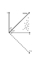
- FIG. 3 is a diagram for assisting in explanation of RG data calculation processing in processing step S13 of FIG. 2;
- FIG. 3 is a diagram for assisting in explanation of RG data calculation processing in processing step S13 of FIG. 2;
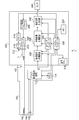
- FIG. 1 is a block diagram showing a configuration of an electronic endoscope system 1 according to an embodiment of the present invention.
- the electronic endoscope system 1 includes an electronic scope 100, a processor 200, and a monitor 300.
- the processor 200 includes a system controller 202 and a timing controller 204.
- the system controller 202 executes various programs stored in the memory 222 and controls the entire electronic endoscope system 1 in an integrated manner.
- the system controller 202 is connected to the operation panel 218.
- the system controller 202 changes each operation of the electronic endoscope system 1 and parameters for each operation in accordance with an instruction from the operator input from the operation panel 218.
- the input instruction by the operator includes, for example, an instruction to switch the operation mode of the electronic endoscope system 1. In the present embodiment, there are a normal mode and a special mode as operation modes.
- the timing controller 204 outputs a clock pulse for adjusting the operation timing of each unit to each circuit in the electronic endoscope system 1.
- the lamp 208 emits white light L after being started by the lamp power igniter 206.
- the lamp 208 is, for example, a high-intensity lamp such as a xenon lamp, a halogen lamp, a mercury lamp, or a metal halide lamp, an LED (Light Emitting Diode), or a laser.
- the white light L emitted from the lamp 208 is limited to an appropriate amount of light through the diaphragm 212 while being collected by the condenser lens 210. Note that since LEDs and lasers have features such as low power consumption and small amount of heat generation compared to other light sources, there is an advantage that a bright image can be acquired while suppressing power consumption and heat generation amount. The ability to acquire a bright image leads to improving the accuracy of evaluation values described later.
- the motor 214 is mechanically connected to the diaphragm 212 via a transmission mechanism such as an arm or gear not shown.
- the motor 214 is a DC motor, for example, and is driven under the drive control of the driver 216.
- the aperture 212 is operated by the motor 214 to change the opening degree so that the image displayed on the display screen of the monitor 300 has an appropriate brightness.
- the amount of white light L emitted from the lamp 208 is limited according to the opening degree of the diaphragm 212.
- the appropriate reference for the brightness of the image is changed according to the brightness adjustment operation of the operation panel 218 by the operator.
- the dimming circuit that controls the brightness by controlling the driver 216 is a well-known circuit and is omitted in this specification.
- the white light L that has passed through the stop 212 is condensed on the incident end face of an LCB (Light Carrying Bundle) 102 and is incident on the LCB 102.
- White light L incident on the LCB 102 from the incident end face propagates in the LCB 102.
- the white light L that has propagated through the LCB 102 is emitted from the emission end face of the LCB 102 disposed at the tip of the electronic scope 100 and irradiates the living tissue via the light distribution lens 104.
- the return light from the living tissue irradiated with the white light L forms an optical image on the light receiving surface of the solid-state image sensor 108 via the objective lens 106.
- the solid-state image sensor 108 is a single-plate color CCD (Charge Coupled Device) image sensor having a Bayer pixel arrangement.
- the solid-state image sensor 108 accumulates an optical image formed by each pixel on the light receiving surface as a charge corresponding to the amount of light, and generates R (Red), G (Green), and B (Blue) image signals. Output.
- an image signal of each pixel (each pixel address) sequentially output from the solid-state image sensor 108 is referred to as a “pixel signal”.
- the solid-state imaging element 108 is not limited to a CCD image sensor, and may be replaced with a CMOS (Complementary Metal Oxide Semiconductor) image sensor or other types of imaging devices.
- the solid-state image sensor 108 may also be one equipped with a complementary color filter.
- An example of the complementary color filter is a CMYG (cyan, magenta, yellow, green) filter.
- the color developability is better than that of the complementary color filter, and the evaluation accuracy can be improved by using the RGB image signal from the image sensor equipped with the primary color filter for the calculation of the inflammation evaluation value.
- the primary color filter it is not necessary to convert a signal in the later-described inflammation evaluation value calculation process, so that it is possible to suppress the processing load of the inflammation evaluation value calculation.
- a driver signal processing circuit 112 is provided in the connection part of the electronic scope 100.
- the pixel signal of the living tissue irradiated with the white light L is input to the driver signal processing circuit 112 from the solid-state imaging device 108 at a frame period.
- the driver signal processing circuit 112 outputs the pixel signal input from the solid-state image sensor 108 to the previous signal processing circuit 220 of the processor 200.
- “frame” may be replaced with “field”.
- the frame period and the field period are 1/30 seconds and 1/60 seconds, respectively.
- the driver signal processing circuit 112 also accesses the memory 114 and reads the unique information of the electronic scope 100.
- the unique information of the electronic scope 100 recorded in the memory 114 includes, for example, the number and sensitivity of the solid-state image sensor 108, the operable frame rate, the model number, and the like.
- the driver signal processing circuit 112 outputs the unique information read from the memory 114 to the system controller 202.
- the system controller 202 performs various calculations based on the unique information of the electronic scope 100 and generates a control signal.
- the system controller 202 controls the operation and timing of various circuits in the processor 200 using the generated control signal so that processing suitable for the electronic scope connected to the processor 200 is performed.
- the timing controller 204 supplies clock pulses to the driver signal processing circuit 112 according to the timing control by the system controller 202.
- the driver signal processing circuit 112 drives and controls the solid-state imaging device 108 at a timing synchronized with the frame rate of the video processed on the processor 200 side, according to the clock pulse supplied from the timing controller 204.
- the pre-stage signal processing circuit 220 performs demosaic processing on the R, G, and B pixel signals input from the driver signal processing circuit 112 at a frame period. Specifically, interpolation processing by G and B peripheral pixels is performed on each R pixel signal, interpolation processing by R and B peripheral pixels is performed on each G pixel signal, and R processing is performed on each B pixel signal. , G interpolation processing is performed on the peripheral pixels. As a result, all pixel signals having only information of one color component are converted into pixel data having information of three color components of R, G, and B.
- the pre-stage signal processing circuit 220 performs predetermined signal processing such as matrix operation, white balance adjustment processing, and gamma correction processing on the pixel data after demosaic processing, and outputs the result to the special image processing circuit 230.
- the image acquisition means for acquiring a color image is configured to include, for example, a solid-state imaging device 108, a driver signal processing circuit 112, and a pre-stage signal processing circuit 220.
- the special image processing circuit 230 outputs the pixel data input from the upstream signal processing circuit 220 to the downstream signal processing circuit 240 through.
- the post-stage signal processing circuit 240 performs predetermined signal processing on the pixel data input from the special image processing circuit 230 to generate screen data for monitor display, and the generated screen data for monitor display is converted to a predetermined video format. Convert to signal.
- the converted video format signal is output to the monitor 300. Thereby, a color image of the living tissue is displayed on the display screen of the monitor 300.
- the pre-stage signal processing circuit 220 performs predetermined image processing such as demosaic processing, matrix calculation, white balance adjustment processing, and gamma correction processing on the pixel signal input from the driver signal processing circuit 112 at a frame period to perform special image processing. Output to the circuit 230.
- FIG. 2 shows a flowchart of special image generation processing by the special image processing circuit 230.
- the special image generation process of FIG. 2 is started when the operation mode of the electronic endoscope system 1 is switched to the special mode.
- FIG. 3 shows an RG plane defined by an R axis and a G axis orthogonal to each other.
- the R axis is the axis of the R component (R pixel value)
- the G axis is the axis of the G component (G pixel value).
- the target pixel data (three-dimensional data) in the RGB space defined by the three primary colors of RGB is converted into two-dimensional data of RG, and according to the R and G pixel values as shown in FIG. Are plotted in the RG plane.
- the point of the target pixel data plotted in the RG plane is referred to as a “target pixel corresponding point”.
- positions the attention pixel data performed in step S13 in RG plane is performed by the arrangement
- the R component In the body cavity of a patient to be imaged, the R component is dominant over other components (G component and B component) due to the influence of hemoglobin pigment and the like. R component) becomes stronger. Therefore, it is considered that the value of the R axis of the target pixel is basically proportional to the intensity of inflammation.
- the color of the captured image in the body cavity changes according to the imaging condition that affects the brightness (for example, the degree of hitting of the white light L).
- the shaded portion where the white light L does not reach is black (achromatic color)
- the portion that is strongly reflected by the white light L and is regularly reflected is white (achromatic color). That is, depending on how white light L hits, the R-axis value of the pixel of interest may take a value that has no correlation with the intensity of inflammation.
- the angle passes through the intersection (origin) of the R axis and the G axis in the RG plane and is at an angle of 45 ° with respect to any of the R axis and the G axis. (Hereinafter, referred to as “white change axis” for convenience of explanation) is defined.
- the white color change axis can be defined as the axis having the highest sensitivity to the brightness of the captured image. Further, for the RG axis (see FIG. 3) orthogonal to the white change axis having the highest sensitivity to the brightness of the captured image, the axis that is least affected by the brightness of the captured image (the effect of the brightness of the captured image). Can be defined as an axis that does not substantially receive
- the distance between the target pixel corresponding point and the white color change axis indicates the intensity of inflammation, and the effect of the brightness of the captured image is substantially reduced. (Not substantially changed in color due to the brightness of the photographed image). Accordingly, in this processing step S13, distance data between the target pixel corresponding point and the white color change axis is calculated for the target pixel selected in processing step S12 (selection of target pixel).
- the RG data that is, the G pixel value is subtracted from the R pixel value for the target pixel selected in the processing step S12 (selection of the target pixel).
- distance (distance along the RG axis) data between the target pixel corresponding point and the white color change axis is obtained.
- the operation for calculating the distance data between the target pixel corresponding point and the white color change axis executed in step S13 is performed by the distance data calculation means.
- FIG. 4 shows RG data (data indicating the intensity of inflammation) calculated in processing step S13 (calculation of RG data).
- the horizontal axis is the axis of RG data.
- reference RG data is defined based on the idea that the inflammation is advanced and the state where the blood itself is visible is the strongest inflammation.
- reference RG data is referred to as “reference RG data”.
- the reference RG data is, for example, an average value of RG data of a plurality of blood image samples taken in advance.
- the RG data calculated in process step S13 is normalized to a value when the reference RG data is set to 1.00.
- the normalized RG data is referred to as “normalized RG data”.
- the normalized RG data is distributed within a range of values 0.20 to 0.40.
- processing step S15 the display color on the color map image of the target pixel selected in processing step S12 (selection of target pixel) is obtained in processing step S14 (normalization processing) based on the above table.
- processing step S14 normalization processing
- the special image generation processing in FIG. 2 executes the processing steps S12 to S15 on the next pixel of interest, so that the processing step S12. Return to (Selecting the pixel of interest).
- This processing step S17 is executed when it is determined that the processing steps S12 to S15 have been executed for all the pixels of the current frame (S16: YES).
- an average value obtained by averaging the normalized RG data of all pixels in the current frame is calculated as an inflammation evaluation value of the entire captured image, and display data of the calculated inflammation evaluation value is generated.
- the operation for calculating the inflammation evaluation value as the predetermined evaluation value for the color image executed in step S17 is performed by the evaluation value calculation means.
- a normal image based on the pixel data that is, pixel data having three color components of RGB
- a processing step S15 display color on the color map image
- the coefficient setting can be appropriately changed by a user operation. If the normal image is to be displayed darker, the coefficient of the normal pixel data is set higher. If the color map image is to be displayed darker, the coefficient of the color map pixel data is set higher.
- the post-stage signal processing circuit 240 generates display data of the overlay image of the normal image and the color map image based on the pixel data added in the processing step S18 (overlay processing) of FIG.
- a masking process for masking the peripheral area (periphery of the image display area) is performed, and screen data for monitor display is generated by superimposing an inflammation evaluation value on the mask area generated by the masking process.
- the post-stage signal processing circuit 240 converts the generated monitor display screen data into a predetermined video format signal and outputs it to the monitor 300.
- the monitor 300 is an image display unit that displays an image in which the pixel having inflammation and the pixel in the normal portion are identifiable in different colors based on the inflammation evaluation value.
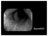
- Fig. 5 shows a screen display example in the special mode.
- a captured image in the body cavity an overlay image in which a normal image and a color map image are displayed in an overlay manner
- an image display area A screen with a mask around is displayed.
- an inflammation evaluation value (score) is displayed in the mask area.
- the inflammation evaluation value (here, the region to be imaged) can be obtained only by performing simple calculation processing without performing nonlinear calculation processing such as tone enhancement processing or complicated color space conversion processing. A value correlated with the increase or decrease of the hemoglobin pigment). That is, the hardware resources necessary for calculating the inflammation evaluation value can be greatly reduced.
- the inflammation evaluation value does not fluctuate due to imaging conditions that affect the brightness of the image (for example, the degree of irradiation light hit), the surgeon can make a more objective and accurate determination of inflammation.
- the endoscope system according to the present embodiment brings about the following effects or problems in the technical field.
- the endoscope system according to the present embodiment is a diagnostic aid for early detection of inflammatory diseases.
- the degree of inflammation can be displayed on the screen, or the image of the area where the inflammation has occurred can be emphasized so that the surgeon can find mild inflammation that is difficult to visually recognize. .
- the effects brought about by the configuration of the present embodiment regarding the evaluation of mild inflammation become remarkable.
- the diagnostic difference between doctors can be reduced.
- the merit of providing an objective evaluation value according to the configuration of the present embodiment to a doctor with little experience is great.
- the load of image processing is reduced, the inflamed part can be displayed as an image in real time, so that the diagnostic accuracy can be improved.
- a color map image an image showing the degree of inflammation
- a normal image can be obtained without delay. Can be displayed side by side or synthesized. Therefore, it is possible to display the color map image without extending the examination time, and as a result, it is possible to avoid an increase in patient burden.
- the observation target part in the present embodiment is, for example, a respiratory organ, a digestive organ, or the like.
- the respiratory organ or the like is, for example, the lung or the ENT.
- Examples of digestive organs include the large intestine, the small intestine, the stomach, the duodenum, and the uterus.
- the endoscope system according to the above-described embodiment is considered to be more effective when the observation target is the large intestine. Specifically, this is due to the following reasons. First, there is a disease that can be evaluated on the basis of inflammation in the large intestine, and the merit of finding an inflamed site is greater than other organs.
- the inflammation evaluation value according to the present embodiment is effective as an index of inflammatory bowel disease (IBD) represented by ulcerative colitis. Since the treatment method for ulcerative colitis has not been established, the use of the endoscope system having the configuration of the present embodiment has an extremely great effect of detecting it early and suppressing its progression.
- the large intestine is an elongated organ as compared with the stomach and the like, and the obtained image has a depth and becomes darker toward the back. According to the present embodiment, it is possible to suppress fluctuations in evaluation values due to changes in brightness in the image. Therefore, when the endoscope system of the present embodiment is applied to large intestine observation, the effect of the present embodiment is remarkable. It becomes. That is, the endoscope system of the present embodiment is preferably a respiratory endoscope system or a digestive system endoscope system, and more preferably a large intestine endoscope system.
- mild inflammation is generally difficult to diagnose
- the configuration of the present embodiment for example, by displaying the result of evaluating the degree of inflammation on the screen, it is possible to prevent the doctor from overlooking the mild inflammation.
- the judgment criteria are not clear, and this is a factor that increases individual differences among doctors.
- an objective evaluation value can be provided to the doctor, so that variation in diagnosis due to individual differences can be reduced.
- the above-described configuration of the present embodiment can be applied not only to the degree of inflammation but also to the evaluation value of various lesions accompanied by cancer, polyps, and other color changes. In these cases, the same advantages as described above can be applied. Effects can be achieved. That is, the evaluation value of the present embodiment is preferably an evaluation value of a lesion with a color change, and includes at least one of an inflammation level, a cancer, and a polyp.
- Embodiments of the present invention are not limited to those described above, and various modifications are possible within the scope of the technical idea of the present invention.
- the embodiment of the present application also includes an embodiment that is exemplarily specified in the specification or a combination of obvious embodiments and the like as appropriate.
- the inflammation evaluation value is calculated using the R component and the G component included in each pixel.
- the R component and the B component are used instead of the R component and the G component. Inflammation assessment values may be calculated.
- evaluation values such as inflammation are calculated using R, G, and B primary color components.
- the configuration for calculating evaluation values according to the present invention uses R, G, and B primary color components. It is not limited to. Instead of using R, G, and B primary color components, C, M, Y, and G (cyan, magenta, yellow, and green) complementary color components are used to evaluate inflammation and the like by the same method as in the above-described embodiment. A value may be calculated.
- the light source unit including the lamp power igniter 206, the lamp 208, the condenser lens 210, the diaphragm 212, the motor 214 and the like is provided integrally with the processor, but the light source unit is separate from the processor. It may be provided as a device.
- a CMOS image sensor may be used in place of the CCD image sensor as the solid-state imaging device 108.
- a CMOS image sensor tends to darken an image as a whole as compared with a CCD image sensor. Therefore, the advantageous effect that the fluctuation of the evaluation value due to the brightness of the image by the configuration of the above-described embodiment can be suppressed becomes more prominent in a situation where a CMOS image sensor is used as the solid-state imaging device.
- the resolution of the image is preferably 1 million pixels or more, more preferably 2 million pixels, and even more preferably 8 million pixels or more.
- the processing load for performing the above-described evaluation value calculation for all the pixels increases.
- the processing load for the evaluation value calculation can be suppressed. In the situation where an image is processed, the advantageous effects of the configuration of the present embodiment are remarkably exhibited.
- all the pixels in the image are processed, but for example, extremely high luminance pixels and extremely low luminance pixels may be excluded from the processing targets. .
- the accuracy of the evaluation value can be improved by setting only the pixels determined to have the luminance within a predetermined reference luminance range as the evaluation value calculation target.
- various types of light sources can be used as the light source used in the endoscope system 1.
- the light source used in the endoscope system 1 there may be a form based on a limited type of light source (for example, a laser is excluded as the type of light source).
- color component used for calculating the evaluation value there may be a form in which the calculation of the evaluation value using hue and saturation is excluded.
Landscapes
- Health & Medical Sciences (AREA)
- Life Sciences & Earth Sciences (AREA)
- Surgery (AREA)
- Engineering & Computer Science (AREA)
- General Health & Medical Sciences (AREA)
- Nuclear Medicine, Radiotherapy & Molecular Imaging (AREA)
- Physics & Mathematics (AREA)
- Medical Informatics (AREA)
- Radiology & Medical Imaging (AREA)
- Animal Behavior & Ethology (AREA)
- Biomedical Technology (AREA)
- Heart & Thoracic Surgery (AREA)
- Pathology (AREA)
- Molecular Biology (AREA)
- Optics & Photonics (AREA)
- Biophysics (AREA)
- Public Health (AREA)
- Veterinary Medicine (AREA)
- Signal Processing (AREA)
- Computer Vision & Pattern Recognition (AREA)
- General Physics & Mathematics (AREA)
- Theoretical Computer Science (AREA)
- Quality & Reliability (AREA)
- Endoscopes (AREA)
- Instruments For Viewing The Inside Of Hollow Bodies (AREA)
- Closed-Circuit Television Systems (AREA)
- Image Analysis (AREA)
- Image Processing (AREA)
Abstract
Description
図1は、本発明の一実施形態に係る電子内視鏡システム1の構成を示すブロック図である。図1に示されるように、電子内視鏡システム1は、電子スコープ100、プロセッサ200及びモニタ300を備えている。
通常モード時のプロセッサ200での信号処理動作を説明する。
次に、特殊モード時のプロセッサ200での信号処理動作を説明する。
図2は、特殊画像処理回路230による特殊画像生成処理のフローチャートを示す。図2の特殊画像生成処理は、電子内視鏡システム1の動作モードが特殊モードに切り替えられた時点で開始される。
本処理ステップS11では、前段信号処理回路220より現フレームの各画素の画素データが入力される。
本処理ステップS12では、全ての画素の中から所定の順序に従い一つの注目画素が選択される。
本処理ステップS13では、処理ステップS12(注目画素の選択)にて選択された注目画素について、R-Gデータが計算される。図3及び図4に、R-Gデータの計算処理の説明を補助する図を示す。
図4に、処理ステップS13(R-Gデータの計算)にて計算されたR-Gデータ(炎症の強さを示すデータ)を示す。図4中、横軸がR-Gデータの軸である。本実施形態では、炎症が進行して血液そのものが見えている状態が最も強い状態の炎症であるという考えに基づき、基準となるR-Gデータが規定されている。以下、説明の便宜上、基準となるR-Gデータを「基準RGデータ」と記す。基準RGデータは、例えば、予め撮影された複数の血液画像サンプルのR-Gデータの平均値である。
本実施形態では、炎症の強さに応じた表示色で撮影画像をモザイク化したカラーマップ画像を表示することができる。カラーマップ画像を表示可能とするため、正規化RGデータの値と所定の表示色とを対応付けたテーブルがメモリ222等の記憶領域に記憶されている。本テーブルでは、例えば、値0.05刻みで異なる表示色が対応付けられている。例示的には、正規化RGデータの値が0.00~0.05の範囲では黄色が対応付けられており、該値が0.05増える毎に色相環での色の並び順に従って異なる表示色が対応付けられており、該値が0.95~1.00の範囲では赤色が対応付けられている。
本処理ステップS16では、現フレームの全ての画素に対して処理ステップS12~S15が実行されたか否かが判定される。
本処理ステップS17は、現フレームの全ての画素に対して処理ステップS12~S15が実行されたと判定された場合(S16:YES)に実行される。本処理ステップS17では、現フレームの全ての画素の正規化RGデータを平均化した平均値が撮影画像全体の炎症評価値として計算され、計算された炎症評価値の表示データが生成される。なお、ステップS17において実行されるカラー画像に対する所定の評価値としての炎症評価値を計算する動作は、評価値計算手段により行われる。
本処理ステップS18では、前段信号処理回路220より入力される画素データ(すなわち、RGBの3つの色成分を持つ画素データ)に基づく通常画像と、処理ステップS15(カラーマップ画像上での表示色の決定)にて所定の表示色に決定された画素データに基づくカラーマップ画像とをオーバレイさせる割合を係数として、前者の画素データ(通常の画素データ)と後者の画素データ(カラーマップ用の画素データ)とが加算される。係数の設定は、ユーザ操作により適宜設定変更することが可能である。通常画像の方を濃く表示したい場合は、通常の画素データの係数が高く設定され、カラーマップ画像の方を濃く表示したい場合は、カラーマップ用の画素データの係数が高く設定される。
本処理ステップS19では、電子内視鏡システム1の動作モードが特殊モードとは別のモードに切り替えられたか否かが判定される。別のモードに切り替えられていないと判定される場合(S19:NO)、図2の特殊画像生成処理は、処理ステップS11(現フレームの画素データの入力)に戻る。一方、別のモードに切り替えられたと判定される場合(S19:YES)、図2の特殊画像生成処理は終了する。
後段信号処理回路240は、図2の処理ステップS18(オーバレイ処理)にて加算処理された画素データに基づいて通常画像とカラーマップ画像とのオーバレイ画像の表示データを生成すると共にモニタ300の表示画面の周辺領域(画像表示領域の周囲)をマスクするマスキング処理を行い、更に、マスキング処理により生成されるマスク領域に炎症評価値を重畳した、モニタ表示用の画面データを生成する。後段信号処理回路240は、生成されたモニタ表示用の画面データを所定のビデオフォーマット信号に変換して、モニタ300に出力する。なお、炎症評価値に基づいて、炎症を有する画素と正常部の画素とが異なる色で識別可能に表された画像を表示する画像表示手段は、例えば、モニタ300である。
Claims (16)
- 少なくとも三つ以上の色成分を持つカラー画像を取得する画像取得手段と、
前記カラー画像を構成する各画素に対応する点を、その色成分に応じて、前記少なくとも三つ以上の色成分のうちの第一の成分の軸である第一の軸と、前記少なくとも三つ以上の色成分のうちの第二の成分の軸であって前記第一の軸と交差する第二の軸とを含む平面内に配置する配置手段と、
前記平面内において前記第一の軸と前記第二の軸との交点を通り且つ該第一の軸、該第二の軸の何れに対しても非平行な第三の軸を定義し、該第三の軸と前記各画素に対応する点との距離データを計算する距離データ計算手段と、
前記計算された距離データに基づいて前記カラー画像に対する所定の評価値を計算する評価値計算手段と、
を備える内視鏡システム。 - 前記カラー画像は、R(Red)、G(Green)、B(Blue)の各色成分を有し、
前記第一の軸はR成分の軸であり、且つ前記第二の軸はG成分又はB成分の軸であり、
前記配置手段は、前記カラー画像を構成する各画素に対応する点を、その色成分に応じて、前記R成分の軸である第一の軸と、前記G成分又は前記B成分の軸である第二の軸とを含む平面内に配置する、
請求項1に記載の内視鏡システム。 - 前記第三の軸は、
前記平面内において前記第一の軸に対して45°の角度をなし且つ前記第二の軸に対して45°の角度をなす軸である、
請求項1又は請求項2に記載の内視鏡システム。 - 前記距離データ計算手段は、
前記各画素について、前記第一の軸の値から前記第二の軸の値を減算することにより、前記距離データを求める、
請求項1から請求項3のいずれか一項に記載の内視鏡システム。 - 前記評価値計算手段は、
前記距離計算手段により計算された第三の軸と各画素に対応する点との距離データを所定の基準距離データを用いて正規化し、正規化された各画素の距離データに基づいて前記カラー画像全体の評価値を計算する、
請求項1から請求項4のいずれか一項に記載の内視鏡システム。 - 前記所定の評価値は、炎症の強さに関する炎症評価値である、
請求項1から請求項5のいずれか一項に記載の内視鏡システム。 - 前記炎症評価値に基づいて、炎症を有する画素と正常部の画素とが異なる色で識別可能に表された画像を表示する画像表示手段を更に備える、
請求項6に記載の内視鏡システム。 - 少なくとも三つ以上の色成分を持つカラー画像を取得する画像取得手段と、
前記カラー画像に対する所定の評価値を計算する評価値計算手段と、を備え、
前記少なくとも三つ以上の色成分は、第一の成分と第二の成分とを含み、
前記評価値計算手段は、前記カラー画像を構成する各画素について第一の成分から第二の成分を減算した値を求め、当該減算した値に基づいて前記評価値を計算する、
内視鏡システム。 - 前記第一の成分がR成分であり、前記第二の成分がG成分又はB成分である、
請求項8に記載の内視鏡システム。 - 少なくとも三つ以上の色成分を持つカラー画像を構成する各画素に対応する点を、その色成分に応じて、前記少なくとも三つ以上の色成分のうちの第一の成分の軸である第一の軸と、前記少なくとも三つ以上の色成分のうちの第二の成分の軸であって前記第一の軸と交差する第二の軸とを含む平面内に配置する配置手段と、
前記平面内において前記第一の軸と前記第二の軸との交点を通り且つ該第一の軸、該第二の軸の何れに対しても非平行な第三の軸を定義し、該第三の軸と前記各画素に対応する点との距離データを計算する距離データ計算手段と、
前記計算された距離データに基づいて前記カラー画像に対する所定の評価値を計算する評価値計算手段と、
を備える評価値計算装置。 - R(Red)、G(Green)、B(Blue)の各色成分を持つカラー画像を構成する各画素に対応する点を、その色成分に応じて、R成分の軸である第一の軸と、該第一の軸と直交するG成分又はB成分の軸である第二の軸とを含む平面内に配置する配置手段と、
前記平面内において前記第一の軸と前記第二の軸との交点を通り且つ該第一の軸、該第二の軸の何れに対しても非平行な第三の軸を定義し、該第三の軸と前記各画素に対応する点との距離データを計算する距離データ計算手段と、
計算された距離データに基づいて前記カラー画像に対する所定の評価値を計算する評価値計算手段と、
を備える、
評価値計算装置。 - 前記第三の軸は、
前記平面内において前記第一の軸に対して45°の角度をなし且つ前記第二の軸に対して45°の角度をなす軸である、
請求項10又は請求項11に記載の評価値計算装置。 - 前記距離データ計算手段は、
前記各画素について、前記第一の軸の値から前記第二の軸の値を減算することにより、前記距離データを求める、
請求項10から請求項12の何れか一項に記載の評価値計算装置。 - 前記評価値計算手段は、
前記距離計算手段により計算された第三の軸と各画素に対応する点との距離データを所定の基準距離データを用いて正規化し、正規化された各画素の距離データに基づいて前記カラー画像全体の評価値を計算する、
請求項10から請求項13の何れか一項に記載の評価値計算装置。 - R、G、Bの各色成分を持つカラー画像を構成する各画素についてR成分からG成分を減算した値を求める減算手段と、
前記減算手段により求められた値に基づいて前記カラー画像に対する所定の評価値を計算する評価値計算手段と、
を備える、
評価値計算装置。 - 前記減算手段は、
前記各画素について、R成分からG成分を減算することに代えて、R成分からB成分を減算する、
請求項15に記載の評価値計算装置。
Priority Applications (4)
| Application Number | Priority Date | Filing Date | Title |
|---|---|---|---|
| DE112016001722.7T DE112016001722T5 (de) | 2015-06-25 | 2016-06-24 | Endoskopsystem und Bewertungswert-Berechnungsvorrichtung |
| JP2016558429A JP6420358B2 (ja) | 2015-06-25 | 2016-06-24 | 内視鏡システム及び評価値計算装置 |
| CN201680015825.8A CN107405050B (zh) | 2015-06-25 | 2016-06-24 | 内窥镜系统以及评价值计算装置 |
| US15/553,966 US10702127B2 (en) | 2015-06-25 | 2016-06-24 | Endoscope system and evaluation value calculation device |
Applications Claiming Priority (2)
| Application Number | Priority Date | Filing Date | Title |
|---|---|---|---|
| JP2015-128001 | 2015-06-25 | ||
| JP2015128001 | 2015-06-25 |
Publications (1)
| Publication Number | Publication Date |
|---|---|
| WO2016208748A1 true WO2016208748A1 (ja) | 2016-12-29 |
Family
ID=57585237
Family Applications (1)
| Application Number | Title | Priority Date | Filing Date |
|---|---|---|---|
| PCT/JP2016/068908 Ceased WO2016208748A1 (ja) | 2015-06-25 | 2016-06-24 | 内視鏡システム及び評価値計算装置 |
Country Status (5)
| Country | Link |
|---|---|
| US (1) | US10702127B2 (ja) |
| JP (1) | JP6420358B2 (ja) |
| CN (1) | CN107405050B (ja) |
| DE (1) | DE112016001722T5 (ja) |
| WO (1) | WO2016208748A1 (ja) |
Cited By (2)
| Publication number | Priority date | Publication date | Assignee | Title |
|---|---|---|---|---|
| WO2019159435A1 (ja) * | 2018-02-13 | 2019-08-22 | Hoya株式会社 | 内視鏡システム |
| WO2024201602A1 (ja) * | 2023-03-24 | 2024-10-03 | 日本電気株式会社 | 情報処理装置、情報処理方法、及び情報処理プログラム |
Families Citing this family (2)
| Publication number | Priority date | Publication date | Assignee | Title |
|---|---|---|---|---|
| DE112018001744T5 (de) * | 2017-03-29 | 2019-12-19 | Sony Corporation | Medizinische Bildgebungsvorrichtung und Endoskop |
| WO2020121906A1 (ja) | 2018-12-13 | 2020-06-18 | ソニー株式会社 | 医療支援システム、医療支援装置及び医療支援方法 |
Citations (8)
| Publication number | Priority date | Publication date | Assignee | Title |
|---|---|---|---|---|
| JPH02224635A (ja) * | 1988-11-02 | 1990-09-06 | Olympus Optical Co Ltd | 内視鏡装置 |
| JPH0490285A (ja) * | 1990-08-01 | 1992-03-24 | Fuji Photo Optical Co Ltd | 電子内視鏡装置 |
| JPH0935056A (ja) * | 1995-07-24 | 1997-02-07 | Olympus Optical Co Ltd | 画像処理装置 |
| JP2003093337A (ja) * | 2001-09-27 | 2003-04-02 | Fuji Photo Optical Co Ltd | 電子内視鏡装置 |
| JP2013051988A (ja) * | 2011-08-31 | 2013-03-21 | Olympus Corp | 画像処理装置、画像処理方法、及び画像処理プログラム |
| JP2014213094A (ja) * | 2013-04-26 | 2014-11-17 | Hoya株式会社 | 病変評価情報生成装置 |
| JP5647752B1 (ja) * | 2013-03-27 | 2015-01-07 | 富士フイルム株式会社 | 画像処理装置及び内視鏡システムの作動方法 |
| JP2015085152A (ja) * | 2013-09-26 | 2015-05-07 | 富士フイルム株式会社 | 内視鏡システム、内視鏡システムのプロセッサ装置、内視鏡システムの作動方法、プロセッサ装置の作動方法 |
Family Cites Families (11)
| Publication number | Priority date | Publication date | Assignee | Title |
|---|---|---|---|---|
| JPS506759B1 (ja) | 1971-04-13 | 1975-03-17 | ||
| JPS5269216A (en) | 1975-12-05 | 1977-06-08 | Matsushita Electric Ind Co Ltd | Still picture and voice transmitting system for stationary picture |
| US6128144A (en) * | 1996-12-02 | 2000-10-03 | Olympus Optical Co., Ltd. | Optical system for camera and camera apparatus |
| US7042488B2 (en) | 2001-09-27 | 2006-05-09 | Fujinon Corporation | Electronic endoscope for highlighting blood vessel |
| US7469069B2 (en) * | 2003-05-16 | 2008-12-23 | Samsung Electronics Co., Ltd. | Method and apparatus for encoding/decoding image using image residue prediction |
| US7333544B2 (en) * | 2003-07-16 | 2008-02-19 | Samsung Electronics Co., Ltd. | Lossless image encoding/decoding method and apparatus using inter-color plane prediction |
| JP5006759B2 (ja) | 2007-10-29 | 2012-08-22 | Hoya株式会社 | 電子内視鏡用信号処理装置および電子内視鏡装置 |
| CN102458215B (zh) * | 2009-06-10 | 2014-05-28 | 奥林巴斯医疗株式会社 | 胶囊型内窥镜装置 |
| JP5576739B2 (ja) * | 2010-08-04 | 2014-08-20 | オリンパス株式会社 | 画像処理装置、画像処理方法、撮像装置及びプログラム |
| JP5331904B2 (ja) * | 2011-04-15 | 2013-10-30 | 富士フイルム株式会社 | 内視鏡システム及び内視鏡システムの作動方法 |
| JP6067264B2 (ja) | 2012-07-17 | 2017-01-25 | Hoya株式会社 | 画像処理装置及び内視鏡装置 |
-
2016
- 2016-06-24 WO PCT/JP2016/068908 patent/WO2016208748A1/ja not_active Ceased
- 2016-06-24 CN CN201680015825.8A patent/CN107405050B/zh active Active
- 2016-06-24 US US15/553,966 patent/US10702127B2/en active Active
- 2016-06-24 DE DE112016001722.7T patent/DE112016001722T5/de active Pending
- 2016-06-24 JP JP2016558429A patent/JP6420358B2/ja active Active
Patent Citations (8)
| Publication number | Priority date | Publication date | Assignee | Title |
|---|---|---|---|---|
| JPH02224635A (ja) * | 1988-11-02 | 1990-09-06 | Olympus Optical Co Ltd | 内視鏡装置 |
| JPH0490285A (ja) * | 1990-08-01 | 1992-03-24 | Fuji Photo Optical Co Ltd | 電子内視鏡装置 |
| JPH0935056A (ja) * | 1995-07-24 | 1997-02-07 | Olympus Optical Co Ltd | 画像処理装置 |
| JP2003093337A (ja) * | 2001-09-27 | 2003-04-02 | Fuji Photo Optical Co Ltd | 電子内視鏡装置 |
| JP2013051988A (ja) * | 2011-08-31 | 2013-03-21 | Olympus Corp | 画像処理装置、画像処理方法、及び画像処理プログラム |
| JP5647752B1 (ja) * | 2013-03-27 | 2015-01-07 | 富士フイルム株式会社 | 画像処理装置及び内視鏡システムの作動方法 |
| JP2014213094A (ja) * | 2013-04-26 | 2014-11-17 | Hoya株式会社 | 病変評価情報生成装置 |
| JP2015085152A (ja) * | 2013-09-26 | 2015-05-07 | 富士フイルム株式会社 | 内視鏡システム、内視鏡システムのプロセッサ装置、内視鏡システムの作動方法、プロセッサ装置の作動方法 |
Cited By (5)
| Publication number | Priority date | Publication date | Assignee | Title |
|---|---|---|---|---|
| WO2019159435A1 (ja) * | 2018-02-13 | 2019-08-22 | Hoya株式会社 | 内視鏡システム |
| WO2019159770A1 (ja) * | 2018-02-13 | 2019-08-22 | Hoya株式会社 | 内視鏡システム |
| JPWO2019159770A1 (ja) * | 2018-02-13 | 2020-12-17 | Hoya株式会社 | 内視鏡システム |
| US11436728B2 (en) | 2018-02-13 | 2022-09-06 | Hoya Corporation | Endoscope system |
| WO2024201602A1 (ja) * | 2023-03-24 | 2024-10-03 | 日本電気株式会社 | 情報処理装置、情報処理方法、及び情報処理プログラム |
Also Published As
| Publication number | Publication date |
|---|---|
| US20180184882A1 (en) | 2018-07-05 |
| DE112016001722T5 (de) | 2017-12-28 |
| CN107405050B (zh) | 2019-11-22 |
| CN107405050A (zh) | 2017-11-28 |
| JPWO2016208748A1 (ja) | 2017-06-29 |
| US10702127B2 (en) | 2020-07-07 |
| JP6420358B2 (ja) | 2018-11-07 |
Similar Documents
| Publication | Publication Date | Title |
|---|---|---|
| JP6125740B1 (ja) | 内視鏡システム及び評価値計算装置 | |
| JP6581730B2 (ja) | 電子内視鏡用プロセッサ及び電子内視鏡システム | |
| US20230112696A1 (en) | Evaluation value calculation device and electronic endoscope system | |
| JP6097629B2 (ja) | 病変評価情報生成装置 | |
| US20230113382A1 (en) | Evaluation value calculation device and electronic endoscope system | |
| JP6591688B2 (ja) | 電子内視鏡用プロセッサ及び電子内視鏡システム | |
| JP6427280B2 (ja) | 補正データ生成方法及び補正データ生成装置 | |
| JP6420358B2 (ja) | 内視鏡システム及び評価値計算装置 | |
| JP6433634B2 (ja) | 電子内視鏡用プロセッサ及び電子内視鏡システム | |
| JP6926242B2 (ja) | 電子内視鏡用プロセッサ及び電子内視鏡システム | |
| JP2018023497A (ja) | 色補正用治具及び電子内視鏡システム |
Legal Events
| Date | Code | Title | Description |
|---|---|---|---|
| ENP | Entry into the national phase |
Ref document number: 2016558429 Country of ref document: JP Kind code of ref document: A |
|
| 121 | Ep: the epo has been informed by wipo that ep was designated in this application |
Ref document number: 16814517 Country of ref document: EP Kind code of ref document: A1 |
|
| WWE | Wipo information: entry into national phase |
Ref document number: 112016001722 Country of ref document: DE |
|
| 122 | Ep: pct application non-entry in european phase |
Ref document number: 16814517 Country of ref document: EP Kind code of ref document: A1 |