WO2016208631A1 - 超音波振動子および超音波プローブ - Google Patents
超音波振動子および超音波プローブ Download PDFInfo
- Publication number
- WO2016208631A1 WO2016208631A1 PCT/JP2016/068538 JP2016068538W WO2016208631A1 WO 2016208631 A1 WO2016208631 A1 WO 2016208631A1 JP 2016068538 W JP2016068538 W JP 2016068538W WO 2016208631 A1 WO2016208631 A1 WO 2016208631A1
- Authority
- WO
- WIPO (PCT)
- Prior art keywords
- ultrasonic
- acoustic matching
- matching layer
- connecting portion
- base material
- Prior art date
Links
- 239000000523 sample Substances 0.000 title claims description 16
- 239000000463 material Substances 0.000 claims description 243
- 238000003780 insertion Methods 0.000 claims description 21
- 230000037431 insertion Effects 0.000 claims description 21
- 239000004020 conductor Substances 0.000 claims description 10
- 238000012986 modification Methods 0.000 description 52
- 230000004048 modification Effects 0.000 description 52
- 239000011295 pitch Substances 0.000 description 47
- 238000004519 manufacturing process Methods 0.000 description 29
- 238000010586 diagram Methods 0.000 description 17
- 238000000465 moulding Methods 0.000 description 10
- 239000011159 matrix material Substances 0.000 description 9
- 239000013078 crystal Substances 0.000 description 8
- 238000005452 bending Methods 0.000 description 7
- 238000005286 illumination Methods 0.000 description 7
- 229910052451 lead zirconate titanate Inorganic materials 0.000 description 6
- 238000000034 method Methods 0.000 description 6
- 210000000056 organ Anatomy 0.000 description 6
- 230000002093 peripheral effect Effects 0.000 description 6
- 239000013307 optical fiber Substances 0.000 description 5
- 238000012545 processing Methods 0.000 description 5
- 239000010409 thin film Substances 0.000 description 5
- 238000002604 ultrasonography Methods 0.000 description 5
- 230000005540 biological transmission Effects 0.000 description 4
- 239000006104 solid solution Substances 0.000 description 4
- HCHKCACWOHOZIP-UHFFFAOYSA-N Zinc Chemical compound [Zn] HCHKCACWOHOZIP-UHFFFAOYSA-N 0.000 description 3
- 239000000853 adhesive Substances 0.000 description 3
- 230000001070 adhesive effect Effects 0.000 description 3
- NKZSPGSOXYXWQA-UHFFFAOYSA-N dioxido(oxo)titanium;lead(2+) Chemical compound [Pb+2].[O-][Ti]([O-])=O NKZSPGSOXYXWQA-UHFFFAOYSA-N 0.000 description 3
- 238000003384 imaging method Methods 0.000 description 3
- 239000007769 metal material Substances 0.000 description 3
- 230000003287 optical effect Effects 0.000 description 3
- 229910052725 zinc Inorganic materials 0.000 description 3
- 239000011701 zinc Substances 0.000 description 3
- FYYHWMGAXLPEAU-UHFFFAOYSA-N Magnesium Chemical compound [Mg] FYYHWMGAXLPEAU-UHFFFAOYSA-N 0.000 description 2
- BQCADISMDOOEFD-UHFFFAOYSA-N Silver Chemical compound [Ag] BQCADISMDOOEFD-UHFFFAOYSA-N 0.000 description 2
- MCMNRKCIXSYSNV-UHFFFAOYSA-N Zirconium dioxide Chemical compound O=[Zr]=O MCMNRKCIXSYSNV-UHFFFAOYSA-N 0.000 description 2
- 210000000013 bile duct Anatomy 0.000 description 2
- 210000003445 biliary tract Anatomy 0.000 description 2
- 210000000621 bronchi Anatomy 0.000 description 2
- 239000002131 composite material Substances 0.000 description 2
- 230000000694 effects Effects 0.000 description 2
- 238000005401 electroluminescence Methods 0.000 description 2
- 239000003822 epoxy resin Substances 0.000 description 2
- 239000000945 filler Substances 0.000 description 2
- 210000000232 gallbladder Anatomy 0.000 description 2
- 229910052738 indium Inorganic materials 0.000 description 2
- APFVFJFRJDLVQX-UHFFFAOYSA-N indium atom Chemical compound [In] APFVFJFRJDLVQX-UHFFFAOYSA-N 0.000 description 2
- HFGPZNIAWCZYJU-UHFFFAOYSA-N lead zirconate titanate Chemical compound [O-2].[O-2].[O-2].[O-2].[O-2].[Ti+4].[Zr+4].[Pb+2] HFGPZNIAWCZYJU-UHFFFAOYSA-N 0.000 description 2
- 210000001165 lymph node Anatomy 0.000 description 2
- 229910052749 magnesium Inorganic materials 0.000 description 2
- 239000011777 magnesium Substances 0.000 description 2
- 210000000496 pancreas Anatomy 0.000 description 2
- 229920000647 polyepoxide Polymers 0.000 description 2
- 230000000241 respiratory effect Effects 0.000 description 2
- 229910052709 silver Inorganic materials 0.000 description 2
- 239000004332 silver Substances 0.000 description 2
- 210000003437 trachea Anatomy 0.000 description 2
- 210000003932 urinary bladder Anatomy 0.000 description 2
- QNRATNLHPGXHMA-XZHTYLCXSA-N (r)-(6-ethoxyquinolin-4-yl)-[(2s,4s,5r)-5-ethyl-1-azabicyclo[2.2.2]octan-2-yl]methanol;hydrochloride Chemical compound Cl.C([C@H]([C@H](C1)CC)C2)CN1[C@@H]2[C@H](O)C1=CC=NC2=CC=C(OCC)C=C21 QNRATNLHPGXHMA-XZHTYLCXSA-N 0.000 description 1
- 239000004697 Polyetherimide Substances 0.000 description 1
- FKSZLDCMQZJMFN-UHFFFAOYSA-N [Mg].[Pb] Chemical compound [Mg].[Pb] FKSZLDCMQZJMFN-UHFFFAOYSA-N 0.000 description 1
- 230000003187 abdominal effect Effects 0.000 description 1
- 239000012814 acoustic material Substances 0.000 description 1
- PNEYBMLMFCGWSK-UHFFFAOYSA-N aluminium oxide Inorganic materials [O-2].[O-2].[O-2].[Al+3].[Al+3] PNEYBMLMFCGWSK-UHFFFAOYSA-N 0.000 description 1
- 230000002238 attenuated effect Effects 0.000 description 1
- 210000004204 blood vessel Anatomy 0.000 description 1
- 230000037237 body shape Effects 0.000 description 1
- 210000000481 breast Anatomy 0.000 description 1
- 229910010293 ceramic material Inorganic materials 0.000 description 1
- 239000000470 constituent Substances 0.000 description 1
- 230000008878 coupling Effects 0.000 description 1
- 238000010168 coupling process Methods 0.000 description 1
- 238000005859 coupling reaction Methods 0.000 description 1
- 230000003111 delayed effect Effects 0.000 description 1
- 238000013461 design Methods 0.000 description 1
- 238000003745 diagnosis Methods 0.000 description 1
- 230000029087 digestion Effects 0.000 description 1
- 210000001198 duodenum Anatomy 0.000 description 1
- 238000002592 echocardiography Methods 0.000 description 1
- 210000003238 esophagus Anatomy 0.000 description 1
- 238000005530 etching Methods 0.000 description 1
- 210000001035 gastrointestinal tract Anatomy 0.000 description 1
- 210000002429 large intestine Anatomy 0.000 description 1
- 239000004973 liquid crystal related substance Substances 0.000 description 1
- 210000004185 liver Anatomy 0.000 description 1
- 210000004072 lung Anatomy 0.000 description 1
- 210000005075 mammary gland Anatomy 0.000 description 1
- 229910052758 niobium Inorganic materials 0.000 description 1
- 239000010955 niobium Substances 0.000 description 1
- GUCVJGMIXFAOAE-UHFFFAOYSA-N niobium atom Chemical compound [Nb] GUCVJGMIXFAOAE-UHFFFAOYSA-N 0.000 description 1
- 238000012634 optical imaging Methods 0.000 description 1
- 210000000277 pancreatic duct Anatomy 0.000 description 1
- 229920001601 polyetherimide Polymers 0.000 description 1
- 239000011116 polymethylpentene Substances 0.000 description 1
- 229920000306 polymethylpentene Polymers 0.000 description 1
- 229920001296 polysiloxane Polymers 0.000 description 1
- 210000002307 prostate Anatomy 0.000 description 1
- 229920005989 resin Polymers 0.000 description 1
- 239000011347 resin Substances 0.000 description 1
- 229910052706 scandium Inorganic materials 0.000 description 1
- SIXSYDAISGFNSX-UHFFFAOYSA-N scandium atom Chemical compound [Sc] SIXSYDAISGFNSX-UHFFFAOYSA-N 0.000 description 1
- 210000002784 stomach Anatomy 0.000 description 1
- 239000000758 substrate Substances 0.000 description 1
- 229910052715 tantalum Inorganic materials 0.000 description 1
- GUVRBAGPIYLISA-UHFFFAOYSA-N tantalum atom Chemical compound [Ta] GUVRBAGPIYLISA-UHFFFAOYSA-N 0.000 description 1
- 210000001685 thyroid gland Anatomy 0.000 description 1
- 210000001519 tissue Anatomy 0.000 description 1
- WFKWXMTUELFFGS-UHFFFAOYSA-N tungsten Chemical compound [W] WFKWXMTUELFFGS-UHFFFAOYSA-N 0.000 description 1
- 229910052721 tungsten Inorganic materials 0.000 description 1
- 239000010937 tungsten Substances 0.000 description 1
- 210000000626 ureter Anatomy 0.000 description 1
- 210000003708 urethra Anatomy 0.000 description 1
Images


Classifications
-
- A—HUMAN NECESSITIES
- A61—MEDICAL OR VETERINARY SCIENCE; HYGIENE
- A61B—DIAGNOSIS; SURGERY; IDENTIFICATION
- A61B8/00—Diagnosis using ultrasonic, sonic or infrasonic waves
- A61B8/44—Constructional features of the ultrasonic, sonic or infrasonic diagnostic device
- A61B8/4483—Constructional features of the ultrasonic, sonic or infrasonic diagnostic device characterised by features of the ultrasound transducer
- A61B8/4494—Constructional features of the ultrasonic, sonic or infrasonic diagnostic device characterised by features of the ultrasound transducer characterised by the arrangement of the transducer elements
-
- B—PERFORMING OPERATIONS; TRANSPORTING
- B06—GENERATING OR TRANSMITTING MECHANICAL VIBRATIONS IN GENERAL
- B06B—METHODS OR APPARATUS FOR GENERATING OR TRANSMITTING MECHANICAL VIBRATIONS OF INFRASONIC, SONIC, OR ULTRASONIC FREQUENCY, e.g. FOR PERFORMING MECHANICAL WORK IN GENERAL
- B06B1/00—Methods or apparatus for generating mechanical vibrations of infrasonic, sonic, or ultrasonic frequency
- B06B1/02—Methods or apparatus for generating mechanical vibrations of infrasonic, sonic, or ultrasonic frequency making use of electrical energy
- B06B1/06—Methods or apparatus for generating mechanical vibrations of infrasonic, sonic, or ultrasonic frequency making use of electrical energy operating with piezoelectric effect or with electrostriction
- B06B1/0607—Methods or apparatus for generating mechanical vibrations of infrasonic, sonic, or ultrasonic frequency making use of electrical energy operating with piezoelectric effect or with electrostriction using multiple elements
- B06B1/0622—Methods or apparatus for generating mechanical vibrations of infrasonic, sonic, or ultrasonic frequency making use of electrical energy operating with piezoelectric effect or with electrostriction using multiple elements on one surface
- B06B1/0633—Cylindrical array
-
- A—HUMAN NECESSITIES
- A61—MEDICAL OR VETERINARY SCIENCE; HYGIENE
- A61B—DIAGNOSIS; SURGERY; IDENTIFICATION
- A61B1/00—Instruments for performing medical examinations of the interior of cavities or tubes of the body by visual or photographical inspection, e.g. endoscopes; Illuminating arrangements therefor
- A61B1/00112—Connection or coupling means
- A61B1/00117—Optical cables in or with an endoscope
-
- A—HUMAN NECESSITIES
- A61—MEDICAL OR VETERINARY SCIENCE; HYGIENE
- A61B—DIAGNOSIS; SURGERY; IDENTIFICATION
- A61B1/00—Instruments for performing medical examinations of the interior of cavities or tubes of the body by visual or photographical inspection, e.g. endoscopes; Illuminating arrangements therefor
- A61B1/06—Instruments for performing medical examinations of the interior of cavities or tubes of the body by visual or photographical inspection, e.g. endoscopes; Illuminating arrangements therefor with illuminating arrangements
- A61B1/0661—Endoscope light sources
- A61B1/0669—Endoscope light sources at proximal end of an endoscope
-
- A—HUMAN NECESSITIES
- A61—MEDICAL OR VETERINARY SCIENCE; HYGIENE
- A61B—DIAGNOSIS; SURGERY; IDENTIFICATION
- A61B8/00—Diagnosis using ultrasonic, sonic or infrasonic waves
- A61B8/12—Diagnosis using ultrasonic, sonic or infrasonic waves in body cavities or body tracts, e.g. by using catheters
-
- A—HUMAN NECESSITIES
- A61—MEDICAL OR VETERINARY SCIENCE; HYGIENE
- A61B—DIAGNOSIS; SURGERY; IDENTIFICATION
- A61B8/00—Diagnosis using ultrasonic, sonic or infrasonic waves
- A61B8/13—Tomography
- A61B8/14—Echo-tomography
-
- A—HUMAN NECESSITIES
- A61—MEDICAL OR VETERINARY SCIENCE; HYGIENE
- A61B—DIAGNOSIS; SURGERY; IDENTIFICATION
- A61B8/00—Diagnosis using ultrasonic, sonic or infrasonic waves
- A61B8/44—Constructional features of the ultrasonic, sonic or infrasonic diagnostic device
- A61B8/4444—Constructional features of the ultrasonic, sonic or infrasonic diagnostic device related to the probe
- A61B8/445—Details of catheter construction
-
- B—PERFORMING OPERATIONS; TRANSPORTING
- B06—GENERATING OR TRANSMITTING MECHANICAL VIBRATIONS IN GENERAL
- B06B—METHODS OR APPARATUS FOR GENERATING OR TRANSMITTING MECHANICAL VIBRATIONS OF INFRASONIC, SONIC, OR ULTRASONIC FREQUENCY, e.g. FOR PERFORMING MECHANICAL WORK IN GENERAL
- B06B1/00—Methods or apparatus for generating mechanical vibrations of infrasonic, sonic, or ultrasonic frequency
- B06B1/02—Methods or apparatus for generating mechanical vibrations of infrasonic, sonic, or ultrasonic frequency making use of electrical energy
- B06B1/06—Methods or apparatus for generating mechanical vibrations of infrasonic, sonic, or ultrasonic frequency making use of electrical energy operating with piezoelectric effect or with electrostriction
- B06B1/0644—Methods or apparatus for generating mechanical vibrations of infrasonic, sonic, or ultrasonic frequency making use of electrical energy operating with piezoelectric effect or with electrostriction using a single piezoelectric element
- B06B1/0662—Methods or apparatus for generating mechanical vibrations of infrasonic, sonic, or ultrasonic frequency making use of electrical energy operating with piezoelectric effect or with electrostriction using a single piezoelectric element with an electrode on the sensitive surface
- B06B1/067—Methods or apparatus for generating mechanical vibrations of infrasonic, sonic, or ultrasonic frequency making use of electrical energy operating with piezoelectric effect or with electrostriction using a single piezoelectric element with an electrode on the sensitive surface which is used as, or combined with, an impedance matching layer
-
- G—PHYSICS
- G10—MUSICAL INSTRUMENTS; ACOUSTICS
- G10K—SOUND-PRODUCING DEVICES; METHODS OR DEVICES FOR PROTECTING AGAINST, OR FOR DAMPING, NOISE OR OTHER ACOUSTIC WAVES IN GENERAL; ACOUSTICS NOT OTHERWISE PROVIDED FOR
- G10K11/00—Methods or devices for transmitting, conducting or directing sound in general; Methods or devices for protecting against, or for damping, noise or other acoustic waves in general
- G10K11/18—Methods or devices for transmitting, conducting or directing sound
- G10K11/26—Sound-focusing or directing, e.g. scanning
- G10K11/30—Sound-focusing or directing, e.g. scanning using refraction, e.g. acoustic lenses
Definitions
- the present invention relates to an ultrasonic transducer and an ultrasonic probe that emit an ultrasonic wave to an observation target, receive an ultrasonic echo reflected by the observation target, convert the ultrasonic echo into an echo signal, and output the echo signal.
- Ultrasound may be applied to observe the characteristics of the biological tissue or material that is the object of observation.
- the ultrasonic transducer transmits an ultrasonic wave to the observation target, receives an ultrasonic echo reflected by the observation target, and the ultrasonic observation apparatus performs a predetermined process on the received ultrasonic echo.
- the ultrasonic observation apparatus performs a predetermined process on the received ultrasonic echo.
- signal processing information on the image and characteristics of the observation target is acquired.
- An ultrasonic transducer converts an electrical pulse signal into an ultrasonic pulse (acoustic pulse) and irradiates the object to be observed, as well as an electrical echo signal that expresses the ultrasonic echo reflected by the object as a voltage change.
- a plurality of elements (ultrasonic elements) that are stacked on the elements and have at least an acoustic matching layer that matches the acoustic impedance between the elements and the observation target. For example, by arranging multiple ultrasonic elements along a predetermined direction and electronically switching the ultrasonic elements involved in transmission / reception or delaying transmission / reception of each ultrasonic element, ultrasonic echoes from the observation target To get.
- Patent Document 1 As a method for producing such an ultrasonic vibrator, a technique for forming a plurality of piezoelectric elements by bonding a base material made of a piezoelectric material to a sheet made of a material constituting a backing material and dividing the base material by dicing.
- Patent Document 1 a convex ultrasonic transducer is manufactured by bending a sheet on which a plurality of piezoelectric elements are formed along the arrangement direction of the piezoelectric elements and bonding the sheet to a backing material having a curved surface.
- the ultrasonic wave emission side between adjacent ultrasonic elements is completely divided.
- the ultrasonic element is diced from the emission side so that the ultrasonic elements are completely separated.
- the pitch of the adjacent ultrasonic element on the side different from the side bonded to the sheet, that is, the ultrasonic wave emission side is dicing. It becomes larger than the pitch when divided.
- the present invention has been made in view of the above, and improves the directivity characteristics of an ultrasonic element and emits ultrasonic waves when the ultrasonic elements are bent along the arrangement direction. It is an object of the present invention to provide an ultrasonic transducer and an ultrasonic probe that can maintain the pitch of 1 at the pitch at the time of division.
- the ultrasonic transducer emits an ultrasonic wave according to an input of an electric signal and converts an ultrasonic wave incident from the outside into an echo signal.
- a plurality of ultrasonic elements having at least one or a plurality of acoustic matching layers stacked on the elements and matching acoustic impedances of the elements and the observation target, and a surface passing through the surface of the acoustic matching layers And a connecting portion that protrudes to the opposite side of the element side and connects adjacent ultrasonic elements among the plurality of ultrasonic elements.
- the ultrasonic transducer according to the present invention is characterized in that, in the above-mentioned invention, the plurality of ultrasonic elements have a curved shape along the arrangement direction.
- the element is provided with a ground electrode for grounding, and the connecting portion is formed using a conductive material, and the ground electrode is electrically connected to the ground electrode. It is characterized by being connected.
- the ultrasonic transducer according to the present invention is characterized in that, in the above invention, the connecting portion is formed using the same material as the acoustic matching layer.
- the ultrasonic element has a plurality of acoustic matching layers, and the connecting portion is formed using the same material as the acoustic matching layer to be connected. It is characterized by that.
- the ultrasonic transducer according to the present invention further includes a backing material that attenuates ultrasonic vibration generated by the operation of the element in the above invention, and the connecting portion is formed using the same material as the backing material. It is characterized by that.
- the ultrasonic transducer according to the present invention further includes an acoustic lens that emits the ultrasonic wave that has passed through the acoustic matching layer to the outside in the above-described invention, and the connecting portion uses the same material as the acoustic lens. It is characterized by being formed.
- the ultrasonic probe according to the present invention is characterized in that the ultrasonic transducer according to the above-described invention is provided at the tip.
- the ultrasonic probe according to the present invention is the ultrasonic endoscope according to the above invention, characterized in that the ultrasonic probe includes the ultrasonic transducer at a tip and includes an insertion portion to be inserted into a subject. .
- the directivity characteristics of the ultrasonic element are improved, and the pitch of the ultrasonic element on the side from which the ultrasonic wave is emitted when the ultrasonic element is curved along the arrangement direction is maintained at the division pitch. There is an effect that can be done.
- FIG. 1 is a diagram schematically showing an endoscope system according to Embodiment 1 of the present invention.
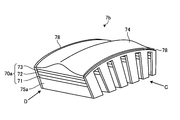
- FIG. 2 is a perspective view schematically showing the distal end configuration of the insertion portion of the ultrasonic endoscope according to the first embodiment of the present invention.
- FIG. 3 is a perspective view schematically showing the configuration of the ultrasonic transducer according to Embodiment 1 of the present invention.
- FIG. 4 is a plan view schematically showing the configuration of the ultrasonic transducer viewed from the direction of arrow A shown in FIG.
- FIG. 5 is a plan view schematically showing the configuration of the ultrasonic transducer viewed from the direction of arrow B shown in FIG.
- FIG. 1 is a diagram schematically showing an endoscope system according to Embodiment 1 of the present invention.
- FIG. 2 is a perspective view schematically showing the distal end configuration of the insertion portion of the ultrasonic endoscope according to the first embodiment of the present invention.
- FIG. 3 is a perspective
- FIG. 6 is a schematic diagram for explaining the method of manufacturing the ultrasonic transducer according to the first embodiment of the present invention.
- FIG. 7 is a schematic diagram for explaining the method of manufacturing the ultrasonic transducer according to the first embodiment of the present invention.
- FIG. 8 is a schematic diagram for explaining a method of manufacturing the ultrasonic transducer according to the first embodiment of the present invention.
- FIG. 9 is a schematic diagram for explaining a method of manufacturing the ultrasonic transducer according to the first embodiment of the present invention.
- FIG. 10 is a plan view schematically showing the configuration of the ultrasonic transducer according to the modification of the first embodiment of the present invention.
- FIG. 11 is a perspective view schematically showing the configuration of the ultrasonic transducer according to the second embodiment of the present invention.
- FIG. 10 is a plan view schematically showing the configuration of the ultrasonic transducer according to the modification of the first embodiment of the present invention.
- FIG. 11 is a perspective view schematically showing the configuration of the
- FIG. 12 is a plan view schematically showing the configuration of the ultrasonic transducer viewed from the direction of arrow C shown in FIG.
- FIG. 13 is a plan view schematically showing the configuration of the ultrasonic transducer viewed from the direction of arrow D shown in FIG.
- FIG. 14 is a schematic diagram for explaining a method of manufacturing an ultrasonic transducer according to the second embodiment of the present invention.
- FIG. 15 is a schematic diagram for explaining the method of manufacturing the ultrasonic transducer according to the second embodiment of the present invention.
- FIG. 16 is a schematic diagram for explaining a method of manufacturing an ultrasonic transducer according to the second embodiment of the present invention.
- FIG. 17 is a schematic diagram for explaining a method of manufacturing an ultrasonic transducer according to the third embodiment of the present invention.
- FIG. 18 is a schematic diagram for explaining a method of manufacturing an ultrasonic transducer according to the third embodiment of the present invention.
- FIG. 19 is a schematic diagram for explaining a method of manufacturing an ultrasonic transducer according to the first modification of the third embodiment of the present invention.
- FIG. 20 is a schematic diagram for explaining a method of manufacturing the ultrasonic transducer according to the first modification of the third embodiment of the present invention.
- FIG. 21 is a top view schematically showing a configuration of a main part of the ultrasonic transducer according to the second modification of the third embodiment of the present invention.
- FIG. 22 is a top view schematically showing the configuration of the main part of the ultrasonic transducer according to Modification 3 of Embodiment 3 of the present invention.
- FIG. 23 is a top view schematically showing a configuration of a main part of the ultrasonic transducer according to the fourth modification of the third embodiment of the present invention.
- FIG. 24 is a top view schematically showing the configuration of the main part of the ultrasonic transducer according to Modification 5 of Embodiment 3 of the present invention.
- FIG. 1 is a diagram schematically showing an endoscope system according to Embodiment 1 of the present invention.
- the endoscope system 1 is a system that performs ultrasonic diagnosis in a subject such as a person using an ultrasonic endoscope.
- the endoscope system 1 includes an ultrasonic endoscope 2, an ultrasonic observation device 3, an endoscope observation device 4, a display device 5, and a light source device 6.
- the ultrasonic endoscope 2 converts an electrical pulse signal received from the ultrasonic observation device 3 into an ultrasonic pulse (acoustic pulse) and irradiates the subject at the tip thereof, and is reflected by the subject.
- the converted ultrasonic echo is converted into an electrical echo signal expressed by a voltage change and output.
- the ultrasonic endoscope 2 usually has an imaging optical system and an imaging device, and is inserted into a digestive tract (esophagus, stomach, duodenum, large intestine) or respiratory organ (trachea / bronchi) of a subject for digestion. It is possible to take images of tubes and respiratory organs. In addition, surrounding organs (pancreas, gallbladder, bile duct, biliary tract, lymph node, mediastinal organ, blood vessel, etc.) can be imaged using ultrasound. In addition, the ultrasonic endoscope 2 has a light guide that guides illumination light to be irradiated onto a subject during optical imaging. The light guide has a distal end portion that reaches the distal end of the insertion portion of the ultrasonic endoscope 2 into the subject, and a proximal end portion that is connected to the light source device 6 that generates illumination light.
- a light guide that guides illumination light to be irradiated onto a subject during optical imaging. The light guide
- the ultrasonic endoscope 2 includes an insertion unit 21, an operation unit 22, a universal cable 23, and a connector 24.
- the insertion part 21 is a part inserted into the subject.
- the insertion portion 21 is connected to the ultrasonic transducer 7 provided on the distal end side, the rigid member 211 that holds the ultrasonic transducer 7, and the proximal end side of the rigid member 211, and can be bent.
- a flexible tube portion 213 connected to the proximal end side of the bending portion 212 and having flexibility.
- a light guide that transmits illumination light supplied from the light source device 6 and a plurality of signal cables that transmit various signals are routed inside the insertion portion 21.
- a treatment instrument insertion passage for inserting the treatment instrument is formed.
- the ultrasonic vibrator 7 may be any of a convex vibrator, a linear vibrator, and a radial vibrator.
- the ultrasonic endoscope 2 is provided with a plurality of piezoelectric elements as an ultrasonic transducer 7 in an array, and the piezoelectric elements involved in transmission / reception are electronically switched, or the transmission / reception of each piezoelectric element is delayed.
- the ultrasonic transducer 7 may be mechanically scanned. The configuration of the ultrasonic transducer 7 will be described later.
- FIG. 2 is a perspective view schematically showing the distal end configuration of the insertion portion of the ultrasonic endoscope according to the first embodiment.
- the rigid member 211 includes an illumination lens 211a that condenses illumination light and emits it outside, an objective lens 211b that forms part of the imaging optical system and captures light from outside, and an insertion A treatment instrument protruding port 211c that communicates with the treatment instrument insertion passage formed in the section 21 and projects the treatment instrument from the distal end of the insertion section 21.
- the operation unit 22 is a part that is connected to the proximal end side of the insertion unit 21 and receives various operations from a doctor or the like. As shown in FIG. 1, the operation unit 22 includes a bending knob 221 for performing a bending operation on the bending unit 212 and a plurality of operation members 222 for performing various operations. In addition, the operation section 22 is formed with a treatment instrument insertion port 223 that communicates with the treatment instrument insertion path and allows the treatment instrument to be inserted into the treatment instrument insertion path.
- the universal cable 23 is a cable that extends from the operation unit 22 and includes a plurality of signal cables that transmit various signals, an optical fiber that transmits illumination light supplied from the light source device 6, and the like.
- the connector 24 is provided at the tip of the universal cable 23.
- the connector 24 includes first to third connector portions 241 to 243 to which the ultrasonic cable 31, the video cable 41, and the optical fiber cable 61 are connected.
- the ultrasonic observation apparatus 3 is electrically connected to the ultrasonic endoscope 2 via the ultrasonic cable 31 (see FIG. 1), and outputs a pulse signal to the ultrasonic endoscope 2 via the ultrasonic cable 31. At the same time, an echo signal is input from the ultrasonic endoscope 2. Then, the ultrasonic observation device 3 performs a predetermined process on the echo signal to generate an ultrasonic image.
- the endoscope observation apparatus 4 is electrically connected to the ultrasonic endoscope 2 via a video cable 41 (see FIG. 1), and receives an image signal from the ultrasonic endoscope 2 via the video cable 41. To do. Then, the endoscope observation apparatus 4 performs a predetermined process on the image signal to generate an endoscope image.
- the display device 5 is configured by using a liquid crystal or organic EL (Electro Luminescence), a projector, a CRT (Cathode Ray Tube), and the like, and an ultrasonic image generated by the ultrasonic observation device 3 or the endoscope observation device 4.
- generated by are displayed.
- the light source device 6 is connected to the ultrasonic endoscope 2 via an optical fiber cable 61 (see FIG. 1), and illumination light that illuminates the inside of the subject via the optical fiber cable 61 is supplied to the ultrasonic endoscope 2. Supply.
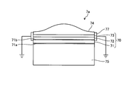
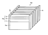
- FIG. 3 is a perspective view schematically showing the configuration of the ultrasonic transducer according to the first embodiment.
- FIG. 4 is a plan view schematically showing the configuration of the ultrasonic transducer viewed from the direction of arrow A shown in FIG.
- FIG. 5 is a plan view schematically showing the configuration of the ultrasonic transducer viewed from the direction of arrow B shown in FIG.
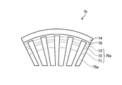
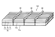
- six piezoelectric elements 71 are arranged side by side.
- the configuration of the ultrasonic transducer 7 is simplified and actually arranged. The number is not limited to this.
- the ultrasonic transducer 7 is a convex ultrasonic transducer as shown in FIG. 2, and is a one-dimensional array (1D array) in which a plurality of piezoelectric elements 71 are arranged in a line. It will be explained as being. In other words, in the ultrasonic transducer 7 according to the first embodiment, the plurality of piezoelectric elements 71 are arranged along the outer surface forming the curved surface of the ultrasonic transducer 7.
- the ultrasonic transducer 7 has a prismatic shape and a plurality of piezoelectric elements 71 arranged in the longitudinal direction and a plurality of piezoelectric elements 71 provided on the outer surface side of the ultrasonic transducer 7.
- Acoustic lens 74 provided on the opposite side of the piezoelectric element 71, backing material 75 provided on the opposite side of the piezoelectric element 71 to the first acoustic matching layer 72, and a connecting portion for connecting adjacent ultrasonic elements 70 to each other. 76.
- the first acoustic matching layer 72 and the second acoustic matching layer 73 are provided for each piezoelectric element 71, and the acoustic lens 74 and the backing material 75 include the plurality of piezoelectric elements 71, the first acoustic matching layer 73 and the first acoustic matching layer 73.
- the acoustic matching layer 72 and the second acoustic matching layer 73 are collectively covered.
- the ultrasonic element 70 includes a piezoelectric element 71, a first acoustic matching layer 72, and a second acoustic matching layer 73.
- the ultrasonic transducer 7 may have one piezoelectric element 71 as an output unit, or may have a plurality of piezoelectric elements 71 as an output unit.
- the longitudinal direction of the piezoelectric elements 71 is referred to as an elevation direction De
- the arrangement direction of the piezoelectric elements 71 is referred to as a scanning direction Ds.
- the piezoelectric element 71 converts an electrical pulse signal into an acoustic pulse and irradiates the subject, and converts an ultrasonic echo reflected by the subject into an electrical echo signal expressed by a voltage change and outputs the electrical echo signal.
- a signal input / output electrode 71a is provided on the main surface on the backing material 75 side, and a ground electrode for grounding is provided on the main surface on the first acoustic matching layer 72 side of the piezoelectric element 71.
- 71b is provided. Each electrode is formed using a conductive metal material or resin material.
- the piezoelectric element 71 is formed using a lead zirconate titanate (PZT) ceramic material, or a PMN-PT single crystal, PMN-PZT single crystal, PZN-PT single crystal, PIN-PZN-PT single crystal, or a relaxor material. Is done.
- PMN-PT single crystal is an abbreviation for solid solution of magnesium lead niobate and lead titanate.
- PMN-PZT single crystal is an abbreviation for solid solution of magnesium / lead niobate and lead zirconate titanate.
- the PZN-PT single crystal is an abbreviation for a solid solution of zinc / lead niobate and lead titanate.
- the PIN-PZN-PT single crystal is an abbreviation for a solid solution of indium / lead niobate, zinc / lead niobate and lead titanate.
- the relaxor-based material is a general term for a three-component piezoelectric material in which lead-based composite perovskite, which is a relaxor material, is added to PZT for the purpose of increasing the piezoelectric constant and dielectric constant.
- the lead-based composite perovskite is represented by Pb (B1, B2) O 3 , B1 is any one of magnesium, zinc, indium, and scandium, and B2 is any one of niobium, tantalum, or tungsten. These materials have an excellent piezoelectric effect. For this reason, even if it reduces in size, the value of an electrical impedance can be made low and it is preferable from a viewpoint of impedance matching with the thin film electrode provided in the piezoelectric element 71.
- the first acoustic matching layer 72 and the second acoustic matching layer 73 match the acoustic impedances of the piezoelectric element 71 and the observation target in order to efficiently transmit sound (ultrasound) between the piezoelectric element 71 and the observation target.
- the first acoustic matching layer 72 and the second acoustic matching layer 73 are made of different materials.
- the first embodiment will be described as having two acoustic matching layers (the first acoustic matching layer 72 and the second acoustic matching layer 73). It is good also as three or more layers.
- the acoustic lens 74 is formed using silicone, polymethylpentene, epoxy resin, polyetherimide, or the like, and has a function of narrowing the ultrasonic wave with one surface being convex or concave, and a second acoustic matching layer.
- the ultrasonic wave that has passed through 73 is emitted to the outside, or an ultrasonic echo from the outside is captured.
- the acoustic lens 74 can be arbitrarily provided, and the acoustic lens 74 may not be provided.
- the backing material 75 attenuates unnecessary ultrasonic vibration generated by the operation of the piezoelectric element 71.
- the backing material 75 is formed using a material having a large attenuation rate, for example, an epoxy resin in which a filler such as alumina or zirconia is dispersed, or a rubber in which the filler is dispersed.
- the connecting portion 76 is formed using the same material as the second acoustic matching layer 73.
- the connecting portion 76 has a comb shape extending along the scanning direction Ds, and a cut is formed according to the interval of the second acoustic matching layer 73.
- the connecting portions 76 are bonded to both ends of the second acoustic matching layer 73 in the elevation direction De, thereby connecting the adjacent second acoustic matching layers 73 to connect the ultrasonic elements 70.
- the connecting portion 76 may be bonded to the piezoelectric element 71 and the first acoustic matching layer 72.
- the connecting portion 76 is bonded to the second acoustic matching layer 73 located on the outer peripheral side when the ultrasonic element 70 is curved as a convex shape, and connects the adjacent second acoustic matching layers 73 to each other. That's fine.
- the connecting portion 76 protrudes with respect to the curved surface passing through the surface of the second acoustic matching layer 73 opposite to the side facing the first acoustic matching layer 72.
- the connecting portion 76 may be provided integrally with the second acoustic matching layer 73.
- the connection part 76 is arrange
- the piezoelectric element 71 is vibrated by the input of the pulse signal, so that the ultrasonic transducer 7 is supervised by the first acoustic matching layer 72, the second acoustic matching layer 73, and the acoustic lens 74. Irradiate sound waves.
- the vibration of the piezoelectric element 71 is attenuated by the backing material 75 on the side opposite to the side where the first acoustic matching layer 72, the second acoustic matching layer 73, and the acoustic lens 74 are disposed. The vibration of 71 is not transmitted.
- the ultrasonic wave reflected from the observation target is transmitted to the piezoelectric element 71 via the first acoustic matching layer 72, the second acoustic matching layer 73, and the acoustic lens 74.
- the piezoelectric element 71 is vibrated by the transmitted ultrasonic wave, and the piezoelectric element 71 converts the vibration into an electrical echo signal, and outputs it as an echo signal to the ultrasonic observation apparatus 3 via a wiring (not shown).
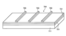
- FIGS. 6 to 9 are schematic diagrams for explaining the method of manufacturing the ultrasonic transducer according to the first embodiment of the present invention.
- a forming member 700 for forming the piezoelectric element 71, the first acoustic matching layer 72 and the second acoustic matching layer 73 is produced.
- a rectangular parallelepiped base material 710 made of a piezoelectric material is formed on one opposing main surface using a material constituting the first acoustic matching layer 72.
- the first acoustic matching layer base material 720 is laminated, and the second acoustic matching layer 73 is formed on the main surface of the first acoustic matching layer base material 720 opposite to the piezoelectric element base material 710 side.
- a rectangular parallelepiped second acoustic matching layer base material 730 formed using the constituent materials is laminated.
- Each base material is bonded by, for example, an adhesive that can pass ultrasonic waves.
- the material constituting the signal input / output electrode 71a and the ground electrode 71b is laminated on the piezoelectric element base material 710. Thereafter, the two opposing end portions of the second acoustic matching layer base material 730 in the laminated base material, which are the end portions forming the side surfaces orthogonal to the laminated surface, are formed using the material constituting the connecting portion 76.
- the prismatic connecting part base material 760 thus formed is bonded.
- the connecting portion base material 760 protrudes from the plane that passes through the surface of the second acoustic matching layer base material 730 that is opposite to the contact side of the first acoustic matching layer base material 720.
- the connecting portion base material 760 is bonded to the laminated base material that is laminated in the order of the piezoelectric element base material 710, the first acoustic matching layer base material 720, and the second acoustic matching layer base material 730.
- a molding member 700 is produced (see FIG. 6).
- a base material in which the second acoustic matching layer base material 730 and the connecting portion base material 760 are integrally formed may be used.
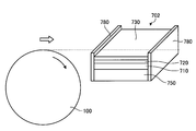
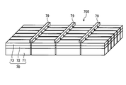
- the molding member 700 is divided, for example, by dicing.
- the forming member 700 is cut by moving the blade 100 along the dividing direction while rotating the blade 100. At this time, the molding member 700 is cut so that a part thereof is connected without being divided.
- the division direction refers to the main surfaces (laminate surfaces) of the piezoelectric element base material 710, the first acoustic matching layer base material 720, and the second acoustic matching layer base material 730, and This is a direction orthogonal to the longitudinal direction of the base material 760 for the connecting portion. Further, the blade 100 moves while maintaining a position where the outer edge slightly protrudes from the surface of the second acoustic matching layer base material 730 and does not cut the connecting portion base material 760.
- the piezoelectric element base material 710, the first acoustic matching layer base material 720, and the second acoustic matching layer base material 730 are divided, and the connecting portion base material 760 is comb-shaped. Is obtained (see FIG. 8).
- a plurality of ultrasonic elements 70 including the piezoelectric element 71, the first acoustic matching layer 72, and the second acoustic matching layer 73, and the connecting portion 76 are formed.
- the laminated body 701 obtained by cutting is curved, the piezoelectric element 71 side is bonded to the backing material 75 (see FIG. 9), and the acoustic lens 74 is provided on the second acoustic matching layer 73 side, thereby FIG.
- the ultrasonic transducer 7 shown can be obtained.
- the pitch between the second acoustic matching layers 73 is divided by dicing even if the stacked body 701 is curved. It is almost equal to the pitch.
- the pitch of the first acoustic matching layer 72 bonded to the second acoustic matching layer 73 and the pitch of the piezoelectric element 71 bonded to the first acoustic matching layer 72 is approximately equal to or divided by the pitch divided by dicing. It becomes narrower and can be miniaturized. That is, in the first embodiment, since the connecting portions 76 are connected so as to maintain the pitch between the second acoustic matching layers 73, the pitch on the outer peripheral side when the stacked body 701 is curved is the piezoelectric element 71. As compared with the pitch on the inner peripheral side which is the side, the pitch becomes substantially equal to or narrower than that and can be miniaturized.
- substantially equivalent includes a change in pitch due to a design error or expansion of the connecting portion 76.
- the case where the plurality of piezoelectric elements 71 and the like are formed by dicing the forming member 700 by the blade 100 has been described as an example. However, the processing by laser, the forming by etching, and the mold are used.
- the molded body shown in FIG. 8 may be produced by molding.
- the acoustic lens 74 is provided after the curved laminate 701 is attached to the backing material 75. However, after the acoustic lens 74 is provided on the curved laminate 701, the backing is provided. It may be attached to the material 75.
- a laminated base material having a substantially prismatic shape in which the piezoelectric element base material 710, the first acoustic matching layer base material 720, and the second acoustic matching layer base material 730 are stacked in this order. Then, the piezoelectric element base material 710, the first acoustic matching layer base material 720, and the second acoustic matching layer base material 730 are divided by dicing or the like into the forming member 700 to which the connecting portion base material 760 is bonded.
- a laminated body 701 in which a plurality of piezoelectric elements 71, a plurality of first acoustic matching layers 72 and a plurality of second acoustic matching layers 73, and a connecting portion 76 are formed is manufactured.
- the ultrasonic vibrator 7 is manufactured by attaching the acoustic lens 74 and the backing material 75 to the laminated body 701 in which the 70s are curved while maintaining the pitch at the time of division. Thereby, the directivity of the ultrasonic element 70 is improved, and the pitch of the ultrasonic element 70 on the side from which the ultrasonic waves are emitted when the plurality of ultrasonic elements 70 are bent along the arrangement direction is divided into the pitches when divided. Can be maintained.
- FIG. 10 is a plan view schematically showing the configuration of the ultrasonic transducer according to the modification of the first embodiment of the present invention.
- FIG. 10 is a plan view corresponding to the arrow B direction shown in FIG.
- the connecting portion 76 has been described as being formed using the same material as that of the second acoustic matching layer 73.
- a conductive material is used as the material of the connecting portion.
- the ultrasonic transducer 7a according to this modification includes a connecting portion 77 instead of the connecting portion 76 of the ultrasonic transducer 7 described above.
- the connecting portion 77 is formed using a conductive material obtained by mixing a conductive paste such as a silver paste. Similarly to the manufacturing method according to the first embodiment described above, the connecting portion 77 is composed of two opposing end portions of the laminated base material, and the connecting portion 77 is formed at an end portion that forms a side surface perpendicular to the laminated surface. It is formed by adhering a prismatic connecting part base material formed using a material to be diced and performing dicing.
- the connecting portion 77 has one end protruding from the end surface of the second acoustic matching layer 73 and the other end extending to the ground electrode 71b in the stacking direction of the piezoelectric element 71, the first acoustic matching layer 72, and the like. It is connected to the ground electrode 71b.
- the connecting portion 77 and the ground electrode 71b are bonded with a conductive adhesive or the like.
- the connecting portion 77 is grounded to the ground potential, and each piezoelectric element 71 is grounded to the ground potential via the connecting portion 77.
- the connecting portion 77 formed of the conductive material is grounded to the ground potential, the pitch when the ultrasonic element 70 is bent can be maintained substantially equal to the pitch when divided.
- the connecting portion 77 can function as a ground connection electrode.
- the piezoelectric elements 71 and the like can be formed only by division by dicing or the like, and connection electrodes for grounding each piezoelectric element 71 to the ground potential can be formed.
- the connecting portions 76 and 77 are provided at both ends in the elevation direction De. However, the connecting portions 76 and 77 are provided only on one of them. Also good. It is only necessary to support the plurality of second acoustic matching layers 73 on at least one end side.
- the connecting portions 76 and 77 are described as being formed using the second acoustic matching layer 73 or the conductive material, but the same material as the acoustic lens 74 is used. May be formed using the same material as the first acoustic matching layer 72, or the first acoustic matching layer 72, the second acoustic matching layer 73, and the acoustic material. Unlike the lens 74, the lens 74 may be formed using a material that can be bent and that can maintain the pitch when divided, for example, a metal material.
- FIG. 11 is a perspective view schematically showing the configuration of the ultrasonic transducer according to the second embodiment of the present invention.
- FIG. 12 is a plan view schematically showing the configuration of the ultrasonic transducer viewed from the direction of arrow C shown in FIG.
- FIG. 13 is a plan view schematically showing the configuration of the ultrasonic transducer viewed from the direction of arrow D shown in FIG.
- the connecting portion 76 has been described as being formed using the same material as that of the second acoustic matching layer 73. However, in Embodiment 2, the same material as that of the backing material 75a is used. A connecting part is formed.
- the ultrasonic transducer 7b includes a plurality of piezoelectric elements 71, a plurality of first acoustic matching layers 72, a plurality of second acoustic matching layers 73, an acoustic lens 74, and piezoelectric elements 71.
- a plurality of backing materials 75a provided on the side opposite to the side in contact with the first acoustic matching layer 72 and a connecting portion 78 for connecting the adjacent ultrasonic elements 70a to each other are provided.
- the ultrasonic element 70 a according to the second embodiment includes a piezoelectric element 71, a first acoustic matching layer 72, and a second acoustic matching layer 73.
- the connecting portion 78 is formed using the same material as the backing material 75a.
- the connecting portion 78 has a comb shape and covers the piezoelectric element 71, the first acoustic matching layer 72, the second acoustic matching layer 73, and the end of the backing material 75a on the elevation direction De side.
- the connecting portion 78 connects the adjacent second acoustic matching layers 73 by being bonded to both ends of the second acoustic matching layer 73 in the elevation direction De.
- the connecting portion 78 protrudes with respect to the surface of the second acoustic matching layer 73 opposite to the first acoustic matching layer 72 side.
- the connecting portion 78 is bonded to at least one of the piezoelectric element 71, the first acoustic matching layer 72, and the second acoustic matching layer 73, and at least the ultrasonic element 70a has the backing material 75a bent when curved as a convex shape.
- the ultrasonic elements 70a adjacent to each other may be connected to each other.
- the connection part 78 may be provided integrally with the backing material 75a.
- FIGS. 14 to 16 are schematic diagrams for explaining a method of manufacturing an ultrasonic transducer according to the second embodiment of the present invention.
- the forming member 702 for forming the piezoelectric element 71, the first acoustic matching layer 72, the second acoustic matching layer 73, and the backing material 75a is manufactured.
- the piezoelectric element base material 710, the first acoustic matching layer base material 720, and the second acoustic matching layer base material 730 are stacked, and the piezoelectric element base material 710 is opposed to the other.
- a rectangular base material 750 for the backing material formed by using the material constituting the backing material 75a is laminated on the main surface of the substrate to produce a laminated base material.
- a plate-shaped base material for connecting portion 780 formed using a material constituting the connecting portion 78 is bonded to the side surface exposed in the stacking order.
- the connecting portion base material 780 is disposed so as to cover the piezoelectric element base material 710, the first acoustic matching layer base material 720, the second acoustic matching layer base material 730, and the backing material base material 750.
- the connecting portion is connected to the laminated base material laminated in the order of the backing material base material 750, the piezoelectric element base material 710, the first acoustic matching layer base material 720, and the second acoustic matching layer base material 730.
- a forming member 702 to which the base material 780 is bonded is produced (see FIG. 14).
- the molding member 702 is divided, for example, by dicing.
- the forming member 702 is cut by moving the blade 100 along the dividing direction while rotating the blade 100.
- the base material for connecting portion 780 is cut so as to be partly connected without being divided.
- the dividing directions in the second embodiment are the main elements of the piezoelectric element base material 710, the first acoustic matching layer base material 720, the second acoustic matching layer base material 730, and the backing material base material 750. This is a direction orthogonal to the surface (laminated surface) and the main surface of the base material for connecting portion 780. Further, the blade 100 moves while maintaining the position where the outer edge slightly protrudes from the surface of the second acoustic matching layer base material 730 and does not cut the connection base material 780.
- the piezoelectric element base material 710 By cutting the forming member 702 by the blade 100, the piezoelectric element base material 710, the first acoustic matching layer base material 720, the second acoustic matching layer base material 730, and the backing material base material 750 are divided, and the connecting portion The base material 780 obtains a laminated body 703 having a comb shape (see FIG. 16).
- a plurality of ultrasonic elements 70a, a plurality of backing materials 75a, and a connecting portion 78 composed of the piezoelectric element 71, the first acoustic matching layer 72, and the second acoustic matching layer 73 are formed.
- the laminated body 703 obtained by cutting is curved, and the acoustic lens 74 is provided on the second acoustic matching layer 73 side, whereby the ultrasonic vibrator 7b shown in FIG. 11 can be obtained.
- the pitch between the ultrasonic elements 70a is the same as that at the time of division by dicing. It becomes almost equal to or narrower than the pitch, and can be miniaturized.
- the pitch on the outer peripheral side when the laminated body 703 is curved is the piezoelectric element 71.
- the pitch becomes substantially equal to or narrower than that and can be miniaturized.
- the surface passing through the end surface of each backing material 75a is flat by applying surface processing to the end of the backing material 75a opposite to the piezoelectric element 71 side.
- each backing material 75a may be a curved surface without being subjected to surface processing, or in a shape suitable for attachment to the distal end of the insertion portion 21. Surface processing may be performed.
- the backing material base material 750, the piezoelectric element base material 710, the first acoustic matching layer base material 720, and the second acoustic matching layer base material 730 are stacked in this order.
- a piezoelectric element base material 710, a first acoustic matching layer base material 720, and a second acoustic matching layer are formed by dicing or the like on a forming member 702 obtained by bonding a connecting base material 780 to a prismatic laminated base material.
- the base material 730 and the backing material base material 780 are divided into a plurality of piezoelectric elements 71, a plurality of first acoustic matching layers 72 and a plurality of second acoustic matching layers 73, and a plurality of backing materials.
- the laminated body 703 in which the 75a and the connecting portion 78 are formed is manufactured, and the acoustic lens 74 is formed on the laminated body 703 in which the adjacent second acoustic matching layers 73 are curved by the connecting portion 78 while maintaining the pitch at the time of division.
- the directivity of the ultrasonic element 70a is improved, and the pitch of the ultrasonic element 70a on the side from which ultrasonic waves are emitted when the ultrasonic element 70a is bent along the arrangement direction is maintained at the pitch at the time of division. can do.
- the connecting portion 78 is described as being bonded to at least the second acoustic matching layer 73.
- the backing material is used.
- the base material 750 and the base material 780 for the connecting portion are manufactured using a base material integrated. Thereby, the number of parts of the manufacturing process and the manufactured ultrasonic vibrator 7b can be reduced, and the ultrasonic vibrator 7b can be manufactured easily.
- the 1D array ultrasonic transducer is described as being manufactured.
- a method of manufacturing the 2D array ultrasonic transducer will be described.
- the plurality of piezoelectric elements 71, the plurality of first acoustic matching layers 72, and the plurality of second acoustic matching layers 73 described above are provided in a matrix, and the piezoelectric element 71 is provided.
- a backing material 75 is provided on the side opposite to the side in contact with the first acoustic matching layer 72 and the adjacent second acoustic matching layers 73 are connected by a connecting portion 79 (see, for example, FIG. 18).
- the piezoelectric element 71, the first acoustic matching layer 72, and the second acoustic matching layer 73 constitute an ultrasonic element.
- 17 and 18 are schematic diagrams for explaining a method of manufacturing an ultrasonic transducer according to the third embodiment of the present invention.
- a forming member 704 for forming the piezoelectric element 71, the first acoustic matching layer 72, and the second acoustic matching layer 73 is manufactured.
- a rectangular-shaped piezoelectric element base material 711 formed using a material constituting the piezoelectric element 71 (including the signal input / output electrode 71a and the ground electrode 71b)
- a first acoustic matching layer base material 721 having a rectangular parallelepiped shape formed using a material constituting the first acoustic matching layer 72, and a surface of the first acoustic matching layer base material 721.
- a rectangular-shaped second acoustic matching layer base material 731 formed using a material constituting the second acoustic matching layer 73 is laminated on the main surface opposite to the piezoelectric element base material 711 side.
- a laminated base material is produced.
- a plurality of connecting portion base materials 790 having a prismatic shape formed using a material constituting the connecting portion 79 are bonded to the main surface of the laminated base material on the second acoustic matching layer base material 731 side.
- the plurality of connecting portion base materials 790 are arranged side by side so as to be parallel to each other.
- the connecting portion base material 790 is bonded to the laminated base material in which the piezoelectric element base material 711, the first acoustic matching layer base material 721, and the second acoustic matching layer base material 731 are stacked in this order.
- a molding member 704 is produced (see FIG. 17).
- the connecting portion base material 790 is formed using a material constituting the first acoustic matching layer 72, the second acoustic matching layer 73, the acoustic lens, or the backing material.
- the molding member 704 is diced. For example, by using a blade 100 that is a blade for dicing as shown in FIG. 7, the forming member 704 is cut by moving the blade 100 along the dividing direction while rotating the blade 100. At this time, the base material for connecting portion 790 is cut so as to be partly connected without being divided.
- the dividing directions in the third embodiment are two directions orthogonal to each other so as to divide the main surface (stacked surface) of the molding member 704 into a matrix shape according to the arrangement of the piezoelectric elements 71.
- the blade 100 moves while maintaining a position where the outer edge slightly protrudes from the surface of the second acoustic matching layer base material 731 and does not cut the connecting part base material 790.
- the piezoelectric element base material 711, the first acoustic matching layer base material 721, and the second acoustic matching layer base material 731 are divided, and the connecting portion base material 790 A stacked body 705 is obtained in which the side surfaces are comb-shaped and the side surfaces orthogonal to the side surfaces are formed with one groove along the longitudinal direction (see FIG. 18).
- a plurality of piezoelectric elements 71, a plurality of first acoustic matching layers 72, a plurality of second acoustic matching layers 73, a plurality of backing materials, and a connecting portion 79 arranged in a matrix are formed.
- the laminated body 705 obtained by cutting is curved, an acoustic lens is provided on the second acoustic matching layer 73 side, and a backing material is provided on the piezoelectric element 71 side, thereby obtaining an ultrasonic transducer of a 2D array. it can.
- the pitch between the second acoustic matching layers 73 is the same as when divided by dicing. The pitch becomes almost the same as or narrower than the pitch of, and miniaturization becomes possible.
- a laminated base material having a substantially prismatic shape in which the piezoelectric element base material 711, the first acoustic matching layer base material 721, and the second acoustic matching layer base material 731 are stacked in this order.
- the piezoelectric element base material 711, the first acoustic matching layer base material 721, and the second acoustic matching layer base material 731 are divided by dicing or the like into the molding member 704 to which the connecting portion base material 790 is bonded.
- a laminated body 705 in which an ultrasonic element including a plurality of piezoelectric elements 71, a plurality of first acoustic matching layers 72, and a plurality of second acoustic matching layers 73 and a connecting portion 79 are formed is manufactured.
- the ultrasonic vibrator 7 is manufactured by attaching an acoustic lens and a backing material to the laminated body 705 in which the second acoustic matching layers 73 to be curved are maintained in a state where the pitch at the time of division is maintained.
- the directivity characteristics of the ultrasonic element can be improved and the pitch of the ultrasonic element on the side from which the ultrasonic wave is emitted when the ultrasonic element is bent along the arrangement direction can be maintained at the division pitch. it can.
- the connecting portion has been described as being formed using a material constituting the first acoustic matching layer, the second acoustic matching layer, the acoustic lens, or the backing material. In the following description, it is assumed that the connecting portion is formed using a conductive material.
- the plurality of piezoelectric elements 71, the plurality of first acoustic matching layers 72, and the plurality of second acoustic matching layers 73 described above are provided in a matrix, and a plurality of second elements are provided.
- the connecting portion 80 is formed using a conductive material obtained by mixing a conductive paste such as a silver paste, or a metal material.
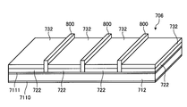
- 19 and 20 are schematic diagrams for explaining a method of manufacturing an ultrasonic transducer according to the first modification of the third embodiment of the present invention.
- a forming member 706 for forming the piezoelectric element 71, the first acoustic matching layer 72, and the second acoustic matching layer 73 is manufactured.
- an electrode thin film 7110 formed using a material constituting the signal input / output electrode 71a is provided on one main surface of the piezoelectric element 71, and the other main surface is provided.
- a connecting portion 80 is formed on the main surface of the electrode thin film 7111 in the rectangular piezoelectric element base material 712 provided with the electrode thin film 7111 formed on the surface using the material constituting the ground electrode 71b.
- a plurality of connecting portion base materials 800 having a prismatic shape formed using a material to be bonded are bonded.
- the plurality of connecting portion base materials 800 are arranged side by side so as to be parallel to each other.
- the electrode thin film 7111 and the connecting portion base material 800 are bonded together with a conductive adhesive or the like.
- first acoustic matching layer base materials 722 having a rectangular shape formed by using the material constituting the first acoustic matching layer 72 are provided between the base materials 800 for the connecting portion.
- the main surface opposite to the piezoelectric element base material 712 side is formed using the material constituting the second acoustic matching layer 73.
- a plurality of second acoustic matching layer base materials 732 having a body shape are stacked to produce a stacked body 707.
- the piezoelectric element base material 712, the first acoustic matching layer base material 722, and the second acoustic matching layer base material 732 are stacked in this order, and the first acoustic matching layer base material 722 and the first acoustic matching layer base material 722 are stacked.
- the forming member 706 in which the base material 800 for the connecting portion is provided between the base materials 732 for the two acoustic matching layers is manufactured (see FIG. 19).
- the molding member 706 is diced. For example, by using a blade 100 as a dicing blade as shown in FIG. 7, the forming member 706 is cut by moving the blade 100 along the dividing direction while rotating the blade 100. At this time, the base material 800 for the connecting portion is cut so as to be partly connected without being divided.
- the piezoelectric element base material 712, the first acoustic matching layer base material 722, and the second acoustic matching layer base material 732 are divided, and the connecting portion base material 800 is one of A stacked body 707 is obtained in which the side surfaces are comb-shaped and the side surfaces orthogonal to the side surfaces are formed with one groove along the longitudinal direction (see FIG. 20).
- the connecting portion 80 connects the ground electrodes 71b of the adjacent piezoelectric elements 71 to each other.
- the laminated body 707 obtained by cutting is curved, an acoustic lens is provided on the second acoustic matching layer 73 side, and a backing material is provided on the piezoelectric element 71 side, thereby obtaining an ultrasonic transducer of a 2D array. it can.
- the piezoelectric element 71 is grounded to the ground potential via the connecting portion 80 by grounding the connecting portion 80 to the ground potential.
- the connecting portion 80 formed of the conductive material is grounded to the ground potential, the piezoelectric element 71, the first acoustic matching layer 72, and the second acoustic matching layer 73 are bent.
- the pitch can be maintained substantially equal to the pitch at the time of division, and the connecting portion 80 can function as a ground connection electrode.
- the piezoelectric elements 71 and the like can be formed only by division by dicing or the like, and connection electrodes for grounding each piezoelectric element 71 to the ground potential can be formed.
- the connecting portion 80 is described as being directly bonded to the ground electrode 71b.
- the connecting portion 79 is formed of a conductive material and the first A through hole or the like may be formed in the acoustic matching layer 72 and the second acoustic matching layer 73, and the ground electrode 71b and the connecting portion 79 may be electrically connected through the through hole.
- FIG. 21 is a top view schematically showing a configuration of a main part of the ultrasonic transducer according to the second modification of the third embodiment of the present invention.
- the connecting portion 79 has been described as collectively holding the second acoustic matching layer 73 corresponding to the piezoelectric elements 71 arranged in one of the arrangement directions of the piezoelectric elements 71.
- a plurality of connecting portions that hold only the second acoustic matching layer 73 to be connected may be provided.
- the second modification as shown in FIG.
- the second acoustic matching layer 73 to be connected (the second modification 2). Then, the connection part 81 is provided in the matrix form so that the corner
- the second modification since the arrangement area of the connecting portion 81 is smaller than that of the connecting portion 79, the influence of ultrasonic propagation by the connecting portion is reduced, and ultrasonic waves are emitted or received in a wider range. can do.
- the shape formed by the outer edge of the connecting portion 81 is described as a rectangle (see FIG. 21), but may be a shape other than a rectangle, such as a circle, an ellipse, or a cross. .
- FIG. 22 is a top view schematically showing the configuration of the main part of the ultrasonic transducer according to Modification 3 of Embodiment 3 of the present invention.
- the plurality of piezoelectric elements 71 are arranged in a matrix, and the shape formed by the outer edge (the shape formed by the outer edge in a top view) is substantially rectangular, and the first acoustic matching layer 72 is formed on the main surface.
- the ultrasonic transducer in which the second acoustic matching layers 73 are sequentially stacked has been described as an example, but the shape formed by the outer edges of the plurality of piezoelectric elements 71 may be a circle or an ellipse.
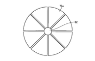
- the description will be made assuming that the shape formed by the outer edges of the plurality of piezoelectric elements 71 forms a circle.
- the second acoustic matching layer 73a laminated on the piezoelectric element via the first acoustic matching layer has a shape formed by dividing the main surface forming a circle into eight equal parts in the radial direction.
- a connecting portion 82 that holds the plurality of second acoustic matching layers 73a is provided at the center. According to the third modification, even when the connecting portion 82 is curved by holding the adjacent second acoustic matching layers 73a at once, the pitch of the adjacent second acoustic matching layers 73a is changed. The pitch at the time of division can be maintained.
- FIG. 23 is a top view schematically showing a configuration of a main part of the ultrasonic transducer according to the fourth modification of the third embodiment of the present invention.
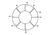
- the shape formed by the outer edges of the plurality of piezoelectric elements 71 is described as a circle or an ellipse.
- the shape formed by the outer edges of the plurality of piezoelectric elements 71 forms a hollow annular shape. It may be a thing.
- the second acoustic matching layer 73b laminated on the piezoelectric element via the first acoustic matching layer has a shape formed by dividing the main surface of which the outer edge forms a circle into eight equal parts, and the adjacent second A plurality of connecting portions 83 that hold the acoustic matching layer 73b are provided. According to the fourth modification, even when the plurality of connecting portions 83 are curved by holding the adjacent second acoustic matching layers 73b, the pitch of the adjacent second acoustic matching layers 73b is changed. The pitch at the time of division can be maintained.
- FIG. 24 is a top view schematically showing the configuration of the main part of the ultrasonic transducer according to Modification 5 of Embodiment 3 of the present invention.
- the shape formed by the outer edges of the plurality of piezoelectric elements 71 is described as a circle or an ellipse, and the main surface forming the circle is divided into eight equal parts in the radial direction. Further, it may be divided along the circumferential direction.
- the second acoustic matching layer 73c laminated on the piezoelectric element via the first acoustic matching layer has a shape that is divided in the circumferential direction and the radial direction, respectively.
- the connecting portion 84 according to the fifth modification extends radially from the center of the circle formed by the outer edges of the plurality of second acoustic matching layers 73c and holds the adjacent second acoustic matching layers 73c. According to the fifth modification, even when the connecting portion 84 is curved by holding the adjacent second acoustic matching layers 73c, the pitch of the adjacent second acoustic matching layers 73c is divided. Pitch can be maintained.
- a plurality of ultrasonic elements are formed by dividing the base material into a matrix or by dividing the base material in the radial direction and / or the circumferential direction.
- a piezoelectric element has been described as an example of outputting an ultrasonic wave and converting an ultrasonic wave incident from the outside into an echo signal.
- the present invention is not limited to this.
- an element manufactured in a MEMS Micro Electro Mechanical Systems
- a C-MUT Capacitive Micromachined Ultrasonic Transducers
- the acoustic lens is described as being disposed in the concave portion formed by the coupling portion and the second acoustic matching layer.
- the surface of the connecting portion may be further covered, or the acoustic lens covers the ultrasonic element and the backing material, that is, the acoustic lens forms the outer peripheral surface of the ultrasonic transducer. Also good.
- Ultrasonic miniature probes are usually inserted into the biliary tract, bile duct, pancreatic duct, trachea, bronchi, urethra, ureter, and used to observe surrounding organs (pancreas, lung, prostate, bladder, lymph nodes, etc.).
- an external ultrasonic probe that irradiates ultrasonic waves from the body surface of the subject may be applied.
- the extracorporeal ultrasonic probe is usually used for observing an abdominal organ (liver, gallbladder, bladder), breast (particularly mammary gland), and thyroid gland.
- the ultrasonic transducer and the ultrasonic probe according to the present invention improve the directivity of the ultrasonic element and emit ultrasonic waves when the ultrasonic element is bent along the arrangement direction. This is useful for maintaining the pitch of the ultrasonic element at the pitch at the time of division.
Abstract
本発明に係る超音波振動子は、電気信号の入力に応じて超音波を出射するとともに、外部から入射した超音波をエコー信号に変換する素子、および素子に積層され、素子と観測対象との音響インピーダンスをマッチングさせる複数の音響整合層を少なくとも有する複数の超音波エレメントと、音響整合層の表面を通過する面に対して素子側と反対側に突出し、複数の超音波エレメントのうち、隣接する超音波エレメント同士を連結する連結部と、を備えた。
Description
本発明は、超音波を観測対象へ出射するとともに、観測対象で反射された超音波エコーを受信してエコー信号に変換して出力する超音波振動子および超音波プローブに関する。
観測対象である生体組織または材料の特性を観測するために、超音波を適用することがある。具体的には、超音波振動子が、観測対象に超音波を送信し、その観測対象によって反射された超音波エコーを受信し、超音波観測装置が、受信した超音波エコーに対して所定の信号処理を施すことにより、観測対象の画像や特性に関する情報を取得する。
超音波振動子は、電気的なパルス信号を超音波パルス(音響パルス)に変換して観測対象へ照射するとともに、観測対象で反射された超音波エコーを電圧変化で表現する電気的なエコー信号に変換して出力する素子、および素子に積層され、この素子と観測対象との音響インピーダンスをマッチングさせる音響整合層を少なくとも有する複数のエレメント(超音波エレメント)を備える。例えば、複数の超音波エレメントを所定の方向に沿って並べて、送受信にかかわる超音波エレメントを電子的に切り替えたり、各超音波エレメントの送受信に遅延をかけたりすることで、観測対象から超音波エコーを取得する。
このような超音波振動子の作製方法として、圧電材料からなる母材を、バッキング材を構成する材料からなるシートに接着し、母材をダイシングにより分割することによって複数の圧電素子を形成する技術が開示されている(例えば、特許文献1を参照)。特許文献1では、複数の圧電素子が形成されたシートを圧電素子の配列方向に沿って湾曲し、曲面を有するバッキング材に接着することで、コンベックス型の超音波振動子を作製している。
ところで、各超音波エレメントの指向特性(エレメントファクタ:Element Factor)を向上するためには、隣接する超音波エレメント間の超音波の出射側が完全に分断されていることが好ましい。特許文献1では、超音波の出射側からダイシングして超音波エレメント間が完全に分断されるように作製している。しかしながら、複数の超音波エレメントが配列されたシートを湾曲させた場合は、隣接する超音波エレメントにおいて、シートに接着されている側と異なる側、すなわち、超音波の出射側のピッチが、ダイシングにより分割された際のピッチよりも大きくなってしまう。
本発明は、上記に鑑みてなされたものであって、超音波エレメントの指向特性を向上するとともに、超音波エレメントを配列方向に沿って湾曲させた際の超音波を出射する側の超音波エレメントのピッチを分割時のピッチに維持することができる超音波振動子および超音波プローブを提供することを目的とする。
上述した課題を解決し、目的を達成するために、本発明に係る超音波振動子は、電気信号の入力に応じて超音波を出射するとともに、外部から入射した超音波をエコー信号に変換する素子、および前記素子に積層され、前記素子と観測対象との音響インピーダンスをマッチングさせる一または複数の音響整合層を少なくとも有する複数の超音波エレメントと、前記音響整合層の表面を通過する面に対して前記素子側と反対側に突出し、前記複数の超音波エレメントのうち、隣接する前記超音波エレメント同士を連結する連結部と、を備えたことを特徴とする。
また、本発明に係る超音波振動子は、上記発明において、前記複数の超音波エレメントが、配列方向に沿って湾曲した形状をなすことを特徴とする。
また、本発明に係る超音波振動子は、上記発明において、前記素子には、グラウンド接地用のグラウンド電極が設けられ、前記連結部は、導電性材料を用いて形成され、前記グラウンド電極と電気的に接続することを特徴とする。
また、本発明に係る超音波振動子は、上記発明において、前記連結部は、前記音響整合層と同じ材料を用いて形成されることを特徴とする。
また、本発明に係る超音波振動子は、上記発明において、前記超音波エレメントは、複数の音響整合層を有し、前記連結部は、連結先の音響整合層と同じ材料を用いて形成されることを特徴とする。
また、本発明に係る超音波振動子は、上記発明において、前記素子の動作によって生じる超音波振動を減衰させるバッキング材をさらに備え、前記連結部は、前記バッキング材と同じ材料を用いて形成されることを特徴とする。
また、本発明に係る超音波振動子は、上記発明において、前記音響整合層を通過した前記超音波を外部に出射する音響レンズをさらに備え、前記連結部は、前記音響レンズと同じ材料を用いて形成されることを特徴とする。
また、本発明に係る超音波プローブは、上記の発明に係る超音波振動子を先端に備えたことを特徴とする。
また、本発明に係る超音波プローブは、上記発明において、前記超音波振動子を先端に有し、被検体内に挿入される挿入部を備えた超音波内視鏡であることを特徴とする。
本発明によれば、超音波エレメントの指向特性を向上するとともに、超音波エレメントを配列方向に沿って湾曲させた際の超音波を出射する側の超音波エレメントのピッチを分割時のピッチに維持することができるという効果を奏する。
以下に、図面を参照して、本発明を実施するための形態(以下、実施の形態)について説明する。なお、以下に説明する実施の形態によって本発明が限定されるものではない。さらに、図面の記載において、同一の部分には同一の符号を付している。
(実施の形態1)
図1は、本発明の実施の形態1に係る内視鏡システムを模式的に示す図である。内視鏡システム1は、超音波内視鏡を用いて人等の被検体内の超音波診断を行うシステムである。この内視鏡システム1は、図1に示すように、超音波内視鏡2と、超音波観測装置3と、内視鏡観察装置4と、表示装置5と、光源装置6とを備える。
図1は、本発明の実施の形態1に係る内視鏡システムを模式的に示す図である。内視鏡システム1は、超音波内視鏡を用いて人等の被検体内の超音波診断を行うシステムである。この内視鏡システム1は、図1に示すように、超音波内視鏡2と、超音波観測装置3と、内視鏡観察装置4と、表示装置5と、光源装置6とを備える。
超音波内視鏡2は、その先端部に、超音波観測装置3から受信した電気的なパルス信号を超音波パルス(音響パルス)に変換して被検体へ照射するとともに、被検体で反射された超音波エコーを電圧変化で表現する電気的なエコー信号に変換して出力する。
超音波内視鏡2は、通常は撮像光学系および撮像素子を有しており、被検体の消化管(食道、胃、十二指腸、大腸)、または呼吸器(気管・気管支)へ挿入され、消化管や、呼吸器の撮像を行うことが可能である。また、その周囲臓器(膵臓、胆嚢、胆管、胆道、リンパ節、縦隔臓器、血管等)を、超音波を用いて撮像することが可能である。また、超音波内視鏡2は、光学撮像時に被検体へ照射する照明光を導くライトガイドを有する。このライトガイドは、先端部が超音波内視鏡2の被検体への挿入部の先端まで達している一方、基端部が照明光を発生する光源装置6に接続されている。
超音波内視鏡2は、図1に示すように、挿入部21と、操作部22と、ユニバーサルケーブル23と、コネクタ24とを備える。挿入部21は、被検体内に挿入される部分である。この挿入部21は、図1に示すように、先端側に設けられる超音波振動子7と、超音波振動子7を保持する硬性部材211と、硬性部材211の基端側に連結され湾曲可能とする湾曲部212と、湾曲部212の基端側に連結され可撓性を有する可撓管部213とを備える。ここで、挿入部21の内部には、具体的な図示は省略したが、光源装置6から供給された照明光を伝送するライトガイド、各種信号を伝送する複数の信号ケーブルが引き回されているとともに、処置具を挿通するための処置具用挿通路が形成されている。
超音波振動子7は、コンベックス振動子、リニア振動子およびラジアル振動子のいずれでも構わない。本実施の形態1では、超音波内視鏡2が、超音波振動子7として複数の圧電素子をアレイ状に設け、送受信にかかわる圧電素子を電子的に切り替えたり、各圧電素子の送受信に遅延をかけたりすることで、電子的に走査させるものとして説明するが、超音波振動子7をメカ的に走査させるものであってもよい。超音波振動子7の構成については、後述する。
図2は、本実施の形態1に係る超音波内視鏡の挿入部の先端構成を模式的に示す斜視図である。図2に示すように、硬性部材211には、照明光を集光して外部に出射する照明レンズ211aと、撮像光学系の一部をなし、外部からの光を取り込む対物レンズ211bと、挿入部21内に形成された処置具用挿通路に連通し、挿入部21の先端から処置具を突出させる処置具突出口211cと、を有する。
操作部22は、挿入部21の基端側に連結され、医師等からの各種操作を受け付ける部分である。この操作部22は、図1に示すように、湾曲部212を湾曲操作するための湾曲ノブ221と、各種操作を行うための複数の操作部材222とを備える。また、操作部22には、処置具用挿通路に連通し、当該処置具用挿通路に処置具を挿通するための処置具挿入口223が形成されている。
ユニバーサルケーブル23は、操作部22から延在し、各種信号を伝送する複数の信号ケーブル、および光源装置6から供給された照明光を伝送する光ファイバ等が配設されたケーブルである。
コネクタ24は、ユニバーサルケーブル23の先端に設けられている。そして、コネクタ24は、超音波ケーブル31、ビデオケーブル41、および光ファイバケーブル61がそれぞれ接続される第1~第3コネクタ部241~243を備える。
超音波観測装置3は、超音波ケーブル31(図1参照)を介して超音波内視鏡2に電気的に接続し、超音波ケーブル31を介して超音波内視鏡2にパルス信号を出力するとともに超音波内視鏡2からエコー信号を入力する。そして、超音波観測装置3は、当該エコー信号に所定の処理を施して超音波画像を生成する。
内視鏡観察装置4は、ビデオケーブル41(図1参照)を介して超音波内視鏡2に電気的に接続し、ビデオケーブル41を介して超音波内視鏡2からの画像信号を入力する。そして、内視鏡観察装置4は、当該画像信号に所定の処理を施して内視鏡画像を生成する。
表示装置5は、液晶または有機EL(Electro Luminescence)、プロジェクタ、CRT(Cathode Ray Tube)などを用いて構成され、超音波観測装置3にて生成された超音波画像や、内視鏡観察装置4にて生成された内視鏡画像等を表示する。
光源装置6は、光ファイバケーブル61(図1参照)を介して超音波内視鏡2に接続し、光ファイバケーブル61を介して被検体内を照明する照明光を超音波内視鏡2に供給する。
続いて、挿入部21の先端に設けられた超音波振動子7の構成を図2~6を参照して説明する。図3は、本実施の形態1に係る超音波振動子の構成を模式的に示す斜視図である。図4は、図3に示す矢視A方向からみた超音波振動子の構成を模式的に示す平面図である。図5は、図3に示す矢視B方向からみた超音波振動子の構成を模式的に示す平面図である。なお、図3,4では、圧電素子71が6個並んでいるものを図示しているが、説明のために超音波振動子7の構成を簡略化した図であり、実際に配設される個数はこの限りではない。本実施の形態1では、超音波振動子7が、図2に示すようなコンベックス型の超音波振動子であって、複数の圧電素子71が一列に配列された一次元アレイ(1Dアレイ)であるものとして説明する。換言すれば、本実施の形態1に係る超音波振動子7では、複数の圧電素子71が、当該超音波振動子7の曲面をなす外表面に沿って配置されている。
超音波振動子7は、角柱状をなし、長手方向を揃えて並べられてなる複数の圧電素子71と、圧電素子71に対し、当該超音波振動子7の外表面側にそれぞれ設けられる複数の第1音響整合層72と、第1音響整合層72の圧電素子71と接する側と反対側に設けられる複数の第2音響整合層73と、第2音響整合層73の第1音響整合層72と接する側と反対側に設けられる音響レンズ74と、圧電素子71の第1音響整合層72と接する側と反対側に設けられるバッキング材75と、隣接する超音波エレメント70同士を連結する連結部76とを有する。なお、本実施の形態1では、第1音響整合層72および第2音響整合層73が、圧電素子71ごとに設けられるとともに、音響レンズ74およびバッキング材75が、複数の圧電素子71、第1音響整合層72および第2音響整合層73を一括して覆う構成をなしている。本実施の形態1にかかる超音波エレメント70は、圧電素子71、第1音響整合層72および第2音響整合層73からなる。超音波振動子7は、一つの圧電素子71を出力単位とするものであってもよいし、複数の圧電素子71を出力単位とするものであってもよい。以下、図2に示すように、圧電素子71の長手方向をエレベーション方向Deとよび、圧電素子71の配列方向を走査方向Dsとよぶ。
圧電素子71は、電気的なパルス信号を音響パルスに変換して被検体へ照射するとともに、被検体で反射された超音波エコーを電圧変化で表現する電気的なエコー信号に変換して出力する。圧電素子71には、例えば、バッキング材75側の主面に信号入出力用電極71aが設けられているとともに、圧電素子71の第1音響整合層72側の主面にグラウンド接地用のグラウンド電極71bが設けられている。各電極は、導電性を有する金属材料または樹脂材料を用いて形成される。
圧電素子71は、チタン酸ジルコン酸鉛(PZT)セラミック材料、またはPMN-PT単結晶、PMN-PZT単結晶、PZN-PT単結晶、PIN-PZN-PT単結晶もしくはリラクサー系材料を用いて形成される。PMN-PT単結晶は、マグネシウム・ニオブ酸鉛およびチタン酸鉛の固溶体の略称である。PMN-PZT単結晶は、マグネシウム・ニオブ酸鉛およびチタン酸ジルコン酸鉛の固溶体の略称である。PZN-PT単結晶は、亜鉛・ニオブ酸鉛およびチタン酸鉛の固溶体の略称である。PIN-PZN-PT単結晶は、インジウム・ニオブ酸鉛、亜鉛・ニオブ酸鉛およびチタン酸鉛の固溶体の略称である。リラクサー系材料は、圧電定数や誘電率を増加させる目的でリラクサー材料である鉛系複合ペロブスカイトをPZTに添加した三成分系圧電材料の総称である。鉛系複合ペロブスカイトは、Pb(B1、B2)O3で表され、B1はマグネシウム、亜鉛、インジウムまたはスカンジウムのいずれかであり、B2はニオブ、タンタルまたはタングステンのいずれかである。これらの材料は、優れた圧電効果を有している。このため、小型化しても電気的なインピーダンスの値を低くすることができ、圧電素子71に設けられる薄膜電極との間のインピーダンスマッチングの観点から好ましい。
第1音響整合層72および第2音響整合層73は、圧電素子71と観測対象との間で音(超音波)を効率よく透過させるために、圧電素子71と観測対象との音響インピーダンスをマッチングさせる。第1音響整合層72および第2音響整合層73は、互いに異なる材料からなる。なお、本実施の形態1では、二つの音響整合層(第1音響整合層72および第2音響整合層73)を有するものとして説明するが、圧電素子71と観測対象との特性により一層としてもよいし、三層以上としてもよい。
音響レンズ74は、シリコーン、ポリメチルペンテンや、エポキシ樹脂、ポリエーテルイミドなどを用いて形成され、一方の面が凸状または凹状をなして超音波を絞る機能を有し、第2音響整合層73を通過した超音波を外部に出射する、または外部からの超音波エコーを取り込む。音響レンズ74については、任意に設けることができ、当該音響レンズ74を有しない構成であってもよい。
バッキング材75は、圧電素子71の動作によって生じる不要な超音波振動を減衰させる。バッキング材75は、減衰率の大きい材料、例えば、アルミナやジルコニア等のフィラーを分散させたエポキシ樹脂や、上述したフィラーを分散したゴムを用いて形成される。
連結部76は、第2音響整合層73と同じ材料を用いて形成される。連結部76は、走査方向Dsに沿って延びる櫛状をなし、第2音響整合層73の間隔に応じた切り込みが形成されている。連結部76は、第2音響整合層73のエレベーション方向Deの両端にそれぞれ接着されることにより、隣接する第2音響整合層73を連結することで、超音波エレメント70を連結する。連結部76は、圧電素子71、第1音響整合層72に接着されるものであってもよい。連結部76は、少なくとも超音波エレメント70において、コンベックス型として湾曲させた際の外周側に位置する第2音響整合層73に接着され、隣接する第2音響整合層73同士を連結するものであればよい。連結部76は、第2音響整合層73の第1音響整合層72と対向する側と反対側の表面を通過する曲面に対して突出している。なお、連結部76は、第2音響整合層73と一体的に設けられるものであってもよい。また、連結部76は、圧電素子71が超音波を送受信する領域(有効領域)から外れた領域に配置されることが好ましい。
以上の構成を有する超音波振動子7は、パルス信号の入力によって圧電素子71が振動することで、第1音響整合層72、第2音響整合層73および音響レンズ74を介して観測対象に超音波を照射する。この際、圧電素子71において、第1音響整合層72、第2音響整合層73および音響レンズ74の配設側と反対側は、バッキング材75により、圧電素子71の振動が減衰され、圧電素子71の振動が伝わらないようになっている。また、観測対象から反射された超音波は、第1音響整合層72、第2音響整合層73および音響レンズ74を介して圧電素子71に伝えられる。伝達された超音波により圧電素子71が振動し、圧電素子71が該振動を電気的なエコー信号に変換して、エコー信号として図示しない配線を介して超音波観測装置3に出力する。
続いて、上述した超音波振動子7を製造する製造方法について、図6~9を参照して説明する。図6~9は、本発明の実施の形態1に係る超音波振動子の製造方法を説明する模式図である。超音波振動子7の製造方法では、まず、圧電素子71、第1音響整合層72および第2音響整合層73を形成するための成形用部材700を作製する。
具体的には、圧電材料からなる長方体状の圧電素子用母材710の対向する一方の主面に、第1音響整合層72を構成する材料を用いて形成された長方体状の第1音響整合層用母材720を積層し、第1音響整合層用母材720の表面であって、圧電素子用母材710側と反対側の主面に、第2音響整合層73を構成する材料を用いて形成された長方体状の第2音響整合層用母材730を積層する。各母材は、例えば、超音波が通過可能な接着剤により接着される。なお、圧電素子用母材710には、信号入出力用電極71aおよびグラウンド電極71bを構成する材料が積層されているものとして説明する。その後、この積層母材における第2音響整合層用母材730の対向する二つの端部であって、積層面と直交する側面をなす端部に、連結部76を構成する材料を用いて形成された角柱状の連結部用母材760を接着する。連結部用母材760は、第2音響整合層用母材730の表面であって、第1音響整合層用母材720の接触側と反対側の表面を通過する平面から突出している。このようにして、圧電素子用母材710、第1音響整合層用母材720、第2音響整合層用母材730の順で積層された積層母材に連結部用母材760を接着した成形用部材700を作製する(図6参照)。なお、第2音響整合層用母材730および連結部用母材760が一体的に形成された母材を用いてもよい。
続いて、圧電素子71、第1音響整合層72および第2音響整合層73からなる複数の超音波エレメント70を形成するため、成形用部材700の分割、例えばダイシングによる分割を行う。例えば、図7に示すような、ダイシング用の刃であるブレード100を用いて、該ブレード100を回転させながら分割方向に沿って移動させることで、成形用部材700を切削する。この際、成形用部材700は、分断されず、一部が繋がるように切削される。ここで、本実施の形態1における分割方向とは、圧電素子用母材710、第1音響整合層用母材720および第2音響整合層用母材730の各主面(積層面)、ならびに連結部用母材760の長手方向と直交する方向である。また、ブレード100は、外縁が、第2音響整合層用母材730の表面から若干突出し、かつ連結部用母材760を切断しない位置を維持して移動する。
ブレード100による成形用部材700の切削によって、圧電素子用母材710、第1音響整合層用母材720、第2音響整合層用母材730は分断され、連結部用母材760は櫛状をなす積層体701を得る(図8参照)。この工程により、圧電素子71、第1音響整合層72および第2音響整合層73からなる複数の超音波エレメント70、ならびに連結部76が形成される。
その後、切削により得られた積層体701を湾曲させ、圧電素子71側をバッキング材75に接合し(図9参照)、第2音響整合層73側に音響レンズ74を設けることによって、図3に示す超音波振動子7を得ることができる。本実施の形態1では、連結部76によって複数の第2音響整合層73が連結されているため、積層体701を湾曲させても、第2音響整合層73間のピッチが、ダイシングにより分割されたピッチとほぼ同等となる。このため、第2音響整合層73に接着されている第1音響整合層72、および第1音響整合層72に接着されている圧電素子71のピッチがダイシングにより分割されたピッチとほぼ同等またはそれより狭くなり、微細化が可能となる。すなわち、本実施の形態1では、連結部76により第2音響整合層73間のピッチを維持するように連結されているため、積層体701を湾曲した際の外周側のピッチが、圧電素子71側である内周側のピッチと比してほぼ同等またはそれより狭くなり、微細化が可能となる。なお、ここでいう「ほぼ同等」とは、設計上の誤差や、連結部76の伸長などによるピッチの変化を含む。
なお、上述した製造方法では、ブレード100による成形用部材700をダイシングすることで、複数の圧電素子71等を形成するものを例に説明したが、レーザーによる加工や、エッチングによる成形、型を用いた成形により図8に示す成形体を作製するものであってもよい。また、上述した製造方法では、湾曲させた積層体701をバッキング材75に取り付けた後、音響レンズ74を設けるものとして説明したが、湾曲させた積層体701に音響レンズ74を設けた後、バッキング材75に取り付けるものであってもよい。
以上説明した本実施の形態1では、圧電素子用母材710、第1音響整合層用母材720、第2音響整合層用母材730の順で積層された略角柱状をなす積層母材に連結部用母材760を接着した成形用部材700に対して、ダイシング等により圧電素子用母材710、第1音響整合層用母材720および第2音響整合層用母材730を分割して、複数の圧電素子71、複数の第1音響整合層72および複数の第2音響整合層73、ならびに連結部76が形成された積層体701を作製し、連結部76により隣接する超音波エレメント70同士を分割時のピッチを維持した状態で湾曲させた積層体701に、音響レンズ74およびバッキング材75を取り付けることによって、超音波振動子7を作製するようにした。これにより、超音波エレメント70の指向特性を向上するとともに、複数の超音波エレメント70を配列方向に沿って湾曲させた際の超音波を出射する側の超音波エレメント70のピッチを分割時のピッチに維持することができる。
(実施の形態1の変形例)
図10は、本発明の実施の形態1の変形例に係る超音波振動子の構成を模式的に示す平面図である。図10は、図3に示す矢視B方向に応じた平面図である。上述した実施の形態1では、連結部76が、第2音響整合層73と同じ材料を用いて形成されるものとして説明したが、本変形例では、連結部の材料として導電性材料を用いる。本変形例にかかる超音波振動子7aは、上述した超音波振動子7の連結部76に代えて、連結部77を有する。
図10は、本発明の実施の形態1の変形例に係る超音波振動子の構成を模式的に示す平面図である。図10は、図3に示す矢視B方向に応じた平面図である。上述した実施の形態1では、連結部76が、第2音響整合層73と同じ材料を用いて形成されるものとして説明したが、本変形例では、連結部の材料として導電性材料を用いる。本変形例にかかる超音波振動子7aは、上述した超音波振動子7の連結部76に代えて、連結部77を有する。
連結部77は、銀ペーストなどの導電性のペーストを混合した導電性材料を用いて形成される。連結部77は、上述した実施の形態1に係る製造方法と同様に、積層母材の対向する二つの端部であって、積層面と直交する側面をなす端部に、連結部77を構成する材料を用いて形成された角柱状の連結部用母材を接着し、ダイシングを行うことによって形成される。本変形例において、連結部77は、圧電素子71、第1音響整合層72等の積層方向において、一端が第2音響整合層73の端面から突出するとともに、他端がグラウンド電極71bまで延びて該グラウンド電極71bに接続している。連結部77とグラウンド電極71bとは、導電性の接着剤等により接着されている。また、連結部77はグラウンド電位に接地されており、各圧電素子71が、該連結部77を介してグラウンド電位に接地している。
本変形例によれば、導電性材料により形成される連結部77をグラウンド電位に接地するようにしたので、超音波エレメント70の湾曲時のピッチを分割時のピッチとほぼ同等に維持することができるとともに、連結部77をグラウンド接続電極として機能させることができる。また、本変形例では、ダイシング等による分割のみで、圧電素子71等を形成するとともに、各圧電素子71がグラウンド電位に接地するための接続電極を形成することができる。
また、上述した実施の形態1および変形例では、エレベーション方向Deの両端部に連結部76,77を設けるものとして説明したが、どちらか一方にのみ連結部76,77を設けるものであってもよい。少なくとも一端側で複数の第2音響整合層73を支持していればよい。
また、上述した実施の形態1および変形例では、連結部76,77が、第2音響整合層73または導電性材料を用いて形成されるものとして説明したが、音響レンズ74と同じ材料を用いて形成されるものであってもよいし、第1音響整合層72と同じ材料を用いて形成されるものであってもよいし、第1音響整合層72、第2音響整合層73および音響レンズ74とは異なり、屈曲自在、かつ分割時のピッチを維持可能な材料、例えば金属材料を用いて形成されるものであってもよい。
(実施の形態2)
図11は、本発明の実施の形態2に係る超音波振動子の構成を模式的に示す斜視図である。図12は、図11に示す矢視C方向からみた超音波振動子の構成を模式的に示す平面図である。図13は、図11に示す矢視D方向からみた超音波振動子の構成を模式的に示す平面図である。上述した実施の形態1では、連結部76が、第2音響整合層73と同じ材料を用いて形成されるものとして説明したが、本実施の形態2では、バッキング材75aと同じ材料を用いて連結部を形成する。
図11は、本発明の実施の形態2に係る超音波振動子の構成を模式的に示す斜視図である。図12は、図11に示す矢視C方向からみた超音波振動子の構成を模式的に示す平面図である。図13は、図11に示す矢視D方向からみた超音波振動子の構成を模式的に示す平面図である。上述した実施の形態1では、連結部76が、第2音響整合層73と同じ材料を用いて形成されるものとして説明したが、本実施の形態2では、バッキング材75aと同じ材料を用いて連結部を形成する。
本実施の形態2に係る超音波振動子7bは、複数の圧電素子71と、複数の第1音響整合層72と、複数の第2音響整合層73と、音響レンズ74と、圧電素子71の第1音響整合層72と接する側と反対側に設けられる複数のバッキング材75aと、隣接する超音波エレメント70a同士を連結する連結部78とを有する。本実施の形態2にかかる超音波エレメント70aは、圧電素子71、第1音響整合層72および第2音響整合層73からなる。
連結部78は、バッキング材75aと同じ材料を用いて形成される。連結部78は、櫛状をなして圧電素子71、第1音響整合層72および第2音響整合層73、バッキング材75aのエレベーション方向De側の端部を覆っている。連結部78は、第2音響整合層73のエレベーション方向Deの両端にそれぞれ接着されることにより、隣接する第2音響整合層73を連結する。連結部78は、第2音響整合層73の第1音響整合層72側と反対側の表面に対して突出している。連結部78は、圧電素子71、第1音響整合層72および第2音響整合層73の少なくとも一つに接着され、少なくとも超音波エレメント70aにおいて、コンベックス型として湾曲させた際に、バッキング材75aを介して隣接する超音波エレメント70a同士を連結するものであればよい。なお、連結部78は、バッキング材75aと一体的に設けられるものであってもよい。
続いて、上述した超音波振動子7bを製造する製造方法について、図14~16を参照して説明する。図14~16は、本発明の実施の形態2に係る超音波振動子の製造方法を説明する模式図である。超音波振動子7bの製造方法では、まず、圧電素子71、第1音響整合層72、第2音響整合層73およびバッキング材75aを形成するための成形用部材702を作製する。
具体的には、上述したように、圧電素子用母材710、第1音響整合層用母材720および第2音響整合層用母材730を積層し、圧電素子用母材710の対向する他方の主面に、バッキング材75aを構成する材料を用いて形成された長方体状のバッキング材用母材750を積層して、積層母材を作製する。その後、この積層母材の対向する二つの側面であって、圧電素子用母材710、第1音響整合層用母材720、第2音響整合層用母材730およびバッキング材用母材750が積層順に露出する側面に、連結部78を構成する材料を用いて形成された平板状の連結部用母材780を接着する。連結部用母材780は、圧電素子用母材710、第1音響整合層用母材720、第2音響整合層用母材730およびバッキング材用母材750を覆うように配設される。このようにして、バッキング材用母材750、圧電素子用母材710、第1音響整合層用母材720、第2音響整合層用母材730の順で積層された積層母材に連結部用母材780を接着した成形用部材702を作製する(図14参照)。
続いて、圧電素子71、第1音響整合層72および第2音響整合層73からなる複数の超音波エレメント70aを形成するため、成形用部材702の分割、例えばダイシングによる分割を行う。例えば、図15に示すような、ダイシング用の刃であるブレード100を用いて、該ブレード100を回転させながら分割方向に沿って移動させることで、成形用部材702を切削する。この際、連結部用母材780は、分断されず、一部が繋がるように切削される。ここで、本実施の形態2における分割方向とは、圧電素子用母材710、第1音響整合層用母材720、第2音響整合層用母材730およびバッキング材用母材750の各主面(積層面)、ならびに連結部用母材780の主面と直交する方向である。また、ブレード100は、外縁が、第2音響整合層用母材730の表面から若干突出し、かつ連結部用母材780を切断しない位置を維持して移動する。
ブレード100による成形用部材702の切削によって、圧電素子用母材710、第1音響整合層用母材720、第2音響整合層用母材730およびバッキング材用母材750は分断され、連結部用母材780は櫛状をなす積層体703を得る(図16参照)。この工程により、圧電素子71、第1音響整合層72および第2音響整合層73からなる複数の超音波エレメント70a、複数のバッキング材75aならびに連結部78が形成される。
その後、切削により得られた積層体703を湾曲させ、第2音響整合層73側に音響レンズ74を設けることによって、図11に示す超音波振動子7bを得ることができる。本実施の形態2では、連結部78によって少なくとも複数の第2音響整合層73が連結されているため、積層体703を湾曲させても、超音波エレメント70a間のピッチが、ダイシングによる分割時のピッチとほぼ同等またはそれより狭くなり、微細化が可能となる。すなわち、本実施の形態2では、連結部78により第2音響整合層73間のピッチを維持するように連結されているため、積層体703を湾曲した際の外周側のピッチが、圧電素子71側である内周側のピッチと比してほぼ同等またはそれより狭くなり、微細化が可能となる。なお、図11,12に示す超音波振動子7bでは、バッキング材75aの圧電素子71側と反対側の端部に表面加工を施すことで、各バッキング材75aの端面を通過する面が平面をなすものとして説明したが、表面加工を施さずに、各バッキング材75aの端面を通過する面が曲面をなすものであってもよいし、挿入部21の先端への取付などに適した形状に表面加工を施すものであってもよい。
以上説明した本実施の形態2では、バッキング材用母材750、圧電素子用母材710、第1音響整合層用母材720、第2音響整合層用母材730の順で積層された略角柱状をなす積層母材に連結部用母材780を接着した成形用部材702に対して、ダイシング等により圧電素子用母材710、第1音響整合層用母材720、第2音響整合層用母材730およびバッキング材用母材780を分割して、複数の圧電素子71、複数の第1音響整合層72および複数の第2音響整合層73からなる超音波エレメント70a、複数のバッキング材75a、ならびに連結部78が形成された積層体703を作製し、連結部78により隣接する第2音響整合層73同士を分割時のピッチを維持した状態で湾曲させた積層体703に音響レンズ74を取り付けることによって、超音波振動子7を作製するようにした。これにより、超音波エレメント70aの指向特性を向上するとともに、超音波エレメント70aを配列方向に沿って湾曲させた際の超音波を出射する側の超音波エレメント70aのピッチを分割時のピッチに維持することができる。
なお、上述した実施の形態2では、連結部78が、少なくとも第2音響整合層73に接着されるものとして説明したが、連結部78がバッキング材75aと一体的に設けられる場合は、バッキング材用母材750と連結部用母材780とが一体化した母材を用いて作製する。これにより、製造過程や作製された超音波振動子7bの部品点数を削減し、超音波振動子7bを簡易に作製することができる。
(実施の形態3)
上述した実施の形態1,2では、1Dアレイの超音波振動子を作製するものとして説明したが、本実施の形態3では、2Dアレイの超音波振動子の作製方法について説明する。本実施の形態3に係る超音波振動子は、上述した複数の圧電素子71、複数の第1音響整合層72、および複数の第2音響整合層73が、マトリクス状に設けられ、圧電素子71の第1音響整合層72と接する側と反対側にバッキング材75が設けられ、連結部79によって隣接する第2音響整合層73同士が連結されるものとして説明する(例えば、図18を参照)。本実施の形態3では、圧電素子71、第1音響整合層72および第2音響整合層73により超音波エレメントを構成する。
上述した実施の形態1,2では、1Dアレイの超音波振動子を作製するものとして説明したが、本実施の形態3では、2Dアレイの超音波振動子の作製方法について説明する。本実施の形態3に係る超音波振動子は、上述した複数の圧電素子71、複数の第1音響整合層72、および複数の第2音響整合層73が、マトリクス状に設けられ、圧電素子71の第1音響整合層72と接する側と反対側にバッキング材75が設けられ、連結部79によって隣接する第2音響整合層73同士が連結されるものとして説明する(例えば、図18を参照)。本実施の形態3では、圧電素子71、第1音響整合層72および第2音響整合層73により超音波エレメントを構成する。
図17,18は、本発明の実施の形態3に係る超音波振動子の製造方法を説明する模式図である。本実施の形態3に係る超音波振動子の製造方法では、まず、圧電素子71、第1音響整合層72および第2音響整合層73を形成するための成形用部材704を作製する。
具体的には、圧電素子71(信号入出力用電極71aおよびグラウンド電極71bを含む)を構成する材料を用いて形成された長方体状の圧電素子用母材711の対向する一方の主面に、第1音響整合層72を構成する材料を用いて形成された長方体状の第1音響整合層用母材721を積層し、第1音響整合層用母材721の表面であって、圧電素子用母材711側と反対側の主面に、第2音響整合層73を構成する材料を用いて形成された長方体状の第2音響整合層用母材731を積層して積層母材を作製する。その後、この積層母材の第2音響整合層用母材731側の主面に、連結部79を構成する材料を用いて形成された角柱状をなす複数の連結部用母材790を接着する。複数の連結部用母材790は、互いに平行となるように並べて配置される。このようにして、圧電素子用母材711、第1音響整合層用母材721、第2音響整合層用母材731の順で積層された積層母材に連結部用母材790を接着した成形用部材704を作製する(図17参照)。なお、連結部用母材790は、第1音響整合層72、第2音響整合層73、音響レンズまたはバッキング材を構成する材料を用いて形成されている。
続いて、圧電素子71、第1音響整合層72および第2音響整合層73を形成するため、成形用部材704のダイシングを行う。例えば、図7に示すような、ダイシング用の刃であるブレード100を用いて、該ブレード100を回転させながら分割方向に沿って移動させることで、成形用部材704を切削する。この際、連結部用母材790は、分断されず、一部が繋がるように切削される。ここで、本実施の形態3における分割方向とは、圧電素子71の配置に応じて成形用部材704の主面(積層面)をマトリクス状に分割するような互いに直交する二つの方向である。また、ブレード100は、外縁が、第2音響整合層用母材731の表面から若干突出し、かつ連結部用母材790を切断しない位置を維持して移動する。
ブレード100による成形用部材704の切削によって、圧電素子用母材711、第1音響整合層用母材721および第2音響整合層用母材731は分断され、連結部用母材790は一方の側面が櫛状をなすとともに、該側面と直交する側面が長手方向に沿って一方の溝が形成された積層体705を得る(図18参照)。この工程により、マトリクス状に配置された複数の圧電素子71、複数の第1音響整合層72、複数の第2音響整合層73および複数のバッキング材、ならびに連結部79が形成される。
その後、切削により得られた積層体705を湾曲させ、第2音響整合層73側に音響レンズを設け、圧電素子71側にバッキング材を設けることによって、2Dアレイの超音波振動子を得ることができる。本実施の形態3では、連結部79によって複数の第2音響整合層73が連結されているため、積層体705を湾曲させても、第2音響整合層73間のピッチが、ダイシングによる分割時のピッチとほぼ同等またはそれより狭くなり、微細化が可能となる。
以上説明した本実施の形態3では、圧電素子用母材711、第1音響整合層用母材721、第2音響整合層用母材731の順で積層された略角柱状をなす積層母材に連結部用母材790を接着した成形用部材704に対して、ダイシング等により圧電素子用母材711、第1音響整合層用母材721および第2音響整合層用母材731を分割して、複数の圧電素子71、複数の第1音響整合層72および複数の第2音響整合層73からなる超音波エレメントならびに連結部79が形成された積層体705を作製し、連結部79により隣接する第2音響整合層73同士を分割時のピッチを維持した状態で湾曲させた積層体705に、音響レンズやバッキング材を取り付けることによって、超音波振動子7を作製するようにした。これにより、超音波エレメントの指向特性を向上するとともに、超音波エレメントを配列方向に沿って湾曲させた際の超音波を出射する側の超音波エレメントのピッチを分割時のピッチに維持することができる。
(実施の形態3の変形例1)
上述した実施の形態3では、連結部が、第1音響整合層、第2音響整合層、音響レンズまたはバッキング材を構成する材料を用いて形成されているものとして説明したが、本変形例1では、連結部が、導電性材料を用いて形成されているものとして説明する。本変形例1に係る超音波振動子は、上述した複数の圧電素子71、複数の第1音響整合層72、および複数の第2音響整合層73が、マトリクス状に設けられ、複数の第2音響整合層73上に音響レンズが設けられ、圧電素子71の第1音響整合層72と接する側と反対側にバッキング材が設けられ、連結部80によって隣接する圧電素子71のグラウンド電極71b同士が連結されるものとして説明する(例えば、図20を参照)。連結部80は、銀ペーストなどの導電性のペーストを混合した導電性材料、または金属材料を用いて形成される。
上述した実施の形態3では、連結部が、第1音響整合層、第2音響整合層、音響レンズまたはバッキング材を構成する材料を用いて形成されているものとして説明したが、本変形例1では、連結部が、導電性材料を用いて形成されているものとして説明する。本変形例1に係る超音波振動子は、上述した複数の圧電素子71、複数の第1音響整合層72、および複数の第2音響整合層73が、マトリクス状に設けられ、複数の第2音響整合層73上に音響レンズが設けられ、圧電素子71の第1音響整合層72と接する側と反対側にバッキング材が設けられ、連結部80によって隣接する圧電素子71のグラウンド電極71b同士が連結されるものとして説明する(例えば、図20を参照)。連結部80は、銀ペーストなどの導電性のペーストを混合した導電性材料、または金属材料を用いて形成される。
図19,20は、本発明の実施の形態3の変形例1に係る超音波振動子の製造方法を説明する模式図である。本変形例1に係る超音波振動子の製造方法では、まず、圧電素子71、第1音響整合層72および第2音響整合層73を形成するための成形用部材706を作製する。
具体的には、圧電素子71を構成する材料を用いて形成され、一方の主面に信号入出力用電極71aを構成する材料を用いて形成された電極用薄膜7110が設けられ、他方の主面にグラウンド電極71bを構成する材料を用いて形成された電極用薄膜7111が設けられた長方体状の圧電素子用母材712において、電極用薄膜7111の主面に、連結部80を構成する材料を用いて形成された角柱状をなす複数の連結部用母材800を接着する。複数の連結部用母材800は、互いに平行となるように並べて配置される。電極用薄膜7111と連結部用母材800とは、導電性の接着剤等により接着されている。
その後、第1音響整合層72を構成する材料を用いて形成された長方体状をなす複数の第1音響整合層用母材722を連結部用母材800間に設ける。その後、第1音響整合層用母材722の表面であって、圧電素子用母材712側と反対側の主面に、第2音響整合層73を構成する材料を用いて形成された長方体状をなす複数の第2音響整合層用母材732を積層して積層体707を作製する。このようにして、圧電素子用母材712、第1音響整合層用母材722、第2音響整合層用母材732の順で積層され、第1音響整合層用母材722間、および第2音響整合層用母材732間に連結部用母材800が設けられた成形用部材706を作製する(図19参照)。
続いて、圧電素子71、第1音響整合層72および第2音響整合層73を形成するため、成形用部材706のダイシングを行う。例えば、図7に示すような、ダイシング用の刃であるブレード100を用いて、該ブレード100を回転させながら分割方向に沿って移動させることで、成形用部材706を切削する。この際、連結部用母材800は、分断されず、一部が繋がるように切削される。
ブレード100による成形用部材706の切削によって、圧電素子用母材712、第1音響整合層用母材722および第2音響整合層用母材732は分断され、連結部用母材800は一方の側面が櫛状をなすとともに、該側面と直交する側面が長手方向に沿って一方の溝が形成された積層体707を得る(図20参照)。この工程により、マトリクス状に配置された複数の圧電素子71、複数の第1音響整合層72、複数の第2音響整合層73および複数のバッキング材、ならびに連結部80が形成される。ここで、連結部80は、隣接する圧電素子71のグラウンド電極71b同士を連結している。
その後、切削により得られた積層体707を湾曲させ、第2音響整合層73側に音響レンズを設け、圧電素子71側にバッキング材を設けることによって、2Dアレイの超音波振動子を得ることができる。本変形例1に係る超音波振動子では、連結部80をグラウンド電位に接地することで、各圧電素子71を、該連結部80を介してグラウンド電位に接地する。
本変形例1によれば、導電性材料により形成される連結部80をグラウンド電位に接地するようにしたので、圧電素子71、第1音響整合層72および第2音響整合層73の湾曲時のピッチを分割時のピッチとほぼ同等に維持することができるとともに、連結部80をグラウンド接続電極として機能させることができる。また、本変形例では、ダイシング等による分割のみで、圧電素子71等を形成するとともに、各圧電素子71がグラウンド電位に接地するための接続電極を形成することができる。
なお、上述した変形例1では、連結部80が、グラウンド電極71bに直接接着されるものとして説明したが、実施の形態3の構成において、連結部79を導電性材料で形成するとともに、第1音響整合層72および第2音響整合層73にスルーホール等を形成し、該スルーホールを介してグラウンド電極71bと連結部79とを電気的に接続するものであってもよい。
(実施の形態3の変形例2)
図21は、本発明の実施の形態3の変形例2に係る超音波振動子の要部の構成を模式的に示す上面図である。上述した実施の形態3では、連結部79が、圧電素子71の配列方向のうちの一方の方向に配列する圧電素子71に応じた第2音響整合層73を一括して保持するものとして説明したが、連結対象の第2音響整合層73のみを保持する連結部を複数設けたものであってもよい。本変形例2では、図21に示すように、マトリクス状に設けられている複数の第2音響整合層73(圧電素子71)のうち、連結対象の第2音響整合層73(本変形例2では、四つの第2音響整合層73)の角部を保持するように、連結部81がマトリクス状に設けられている。本変形例2によれば、連結部81の配設面積が、連結部79と比して小さいため、連結部による超音波の伝搬の影響を少なくし、一層広範囲に超音波を出射、または受信することができる。なお、本変形例2では、連結部81の外縁のなす形状が矩形をなす(図21参照)ものとして説明したが、円や楕円、十文字など、矩形以外の形状をなすものであってもよい。
図21は、本発明の実施の形態3の変形例2に係る超音波振動子の要部の構成を模式的に示す上面図である。上述した実施の形態3では、連結部79が、圧電素子71の配列方向のうちの一方の方向に配列する圧電素子71に応じた第2音響整合層73を一括して保持するものとして説明したが、連結対象の第2音響整合層73のみを保持する連結部を複数設けたものであってもよい。本変形例2では、図21に示すように、マトリクス状に設けられている複数の第2音響整合層73(圧電素子71)のうち、連結対象の第2音響整合層73(本変形例2では、四つの第2音響整合層73)の角部を保持するように、連結部81がマトリクス状に設けられている。本変形例2によれば、連結部81の配設面積が、連結部79と比して小さいため、連結部による超音波の伝搬の影響を少なくし、一層広範囲に超音波を出射、または受信することができる。なお、本変形例2では、連結部81の外縁のなす形状が矩形をなす(図21参照)ものとして説明したが、円や楕円、十文字など、矩形以外の形状をなすものであってもよい。
(実施の形態3の変形例3)
図22は、本発明の実施の形態3の変形例3に係る超音波振動子の要部の構成を模式的に示す上面図である。上述した実施の形態3では、複数の圧電素子71がマトリクス状に配置され、外縁のなす形状(上面視における外縁のなす形状)が略矩形であって、その主面に第1音響整合層72、第2音響整合層73が順に積層された超音波振動子を例に説明したが、複数の圧電素子71の外縁のなす形状が円や楕円をなすものであってもよい。本変形例3では、複数の圧電素子71の外縁のなす形状が、円をなすものとして説明する。本変形例3では、第1音響整合層を介して圧電素子に積層される第2音響整合層73aが、円をなす主面を径方向に八等分してなる形状をなし、該円の中心部に当該複数の第2音響整合層73aを保持する連結部82が設けられる。本変形例3によれば、連結部82が、隣接する第2音響整合層73aを一括して保持することで、湾曲させた場合であっても、隣接する第2音響整合層73aのピッチを分割時のピッチに維持することができる。
図22は、本発明の実施の形態3の変形例3に係る超音波振動子の要部の構成を模式的に示す上面図である。上述した実施の形態3では、複数の圧電素子71がマトリクス状に配置され、外縁のなす形状(上面視における外縁のなす形状)が略矩形であって、その主面に第1音響整合層72、第2音響整合層73が順に積層された超音波振動子を例に説明したが、複数の圧電素子71の外縁のなす形状が円や楕円をなすものであってもよい。本変形例3では、複数の圧電素子71の外縁のなす形状が、円をなすものとして説明する。本変形例3では、第1音響整合層を介して圧電素子に積層される第2音響整合層73aが、円をなす主面を径方向に八等分してなる形状をなし、該円の中心部に当該複数の第2音響整合層73aを保持する連結部82が設けられる。本変形例3によれば、連結部82が、隣接する第2音響整合層73aを一括して保持することで、湾曲させた場合であっても、隣接する第2音響整合層73aのピッチを分割時のピッチに維持することができる。
(実施の形態3の変形例4)
図23は、本発明の実施の形態3の変形例4に係る超音波振動子の要部の構成を模式的に示す上面図である。上述した実施の形態3の変形例3では、複数の圧電素子71の外縁のなす形状が円や楕円をなすものとして説明したが、複数の圧電素子71の外縁のなす形状が中空円環状をなすものであってもよい。本変形例4では、第1音響整合層を介して圧電素子に積層される第2音響整合層73bが、外縁が円をなす主面を八等分してなる形状をなし、隣接する第2音響整合層73bを保持する複数の連結部83が設けられている。本変形例4によれば、複数の連結部83が、隣接する第2音響整合層73bをそれぞれ保持することで、湾曲させた場合であっても、隣接する第2音響整合層73bのピッチを分割時のピッチに維持することができる。
図23は、本発明の実施の形態3の変形例4に係る超音波振動子の要部の構成を模式的に示す上面図である。上述した実施の形態3の変形例3では、複数の圧電素子71の外縁のなす形状が円や楕円をなすものとして説明したが、複数の圧電素子71の外縁のなす形状が中空円環状をなすものであってもよい。本変形例4では、第1音響整合層を介して圧電素子に積層される第2音響整合層73bが、外縁が円をなす主面を八等分してなる形状をなし、隣接する第2音響整合層73bを保持する複数の連結部83が設けられている。本変形例4によれば、複数の連結部83が、隣接する第2音響整合層73bをそれぞれ保持することで、湾曲させた場合であっても、隣接する第2音響整合層73bのピッチを分割時のピッチに維持することができる。
(実施の形態3の変形例5)
図24は、本発明の実施の形態3の変形例5に係る超音波振動子の要部の構成を模式的に示す上面図である。上述した実施の形態3の変形例3では、複数の圧電素子71の外縁のなす形状が円や楕円をなし、円をなす主面を径方向に八等分に分割したものとして説明したが、さらに周方向に沿って分割したものであってもよい。本変形例5では、第1音響整合層を介して圧電素子に積層される第2音響整合層73cが、周方向および径方向にそれぞれ分割されてなる形状をなしている。本変形例5に係る連結部84は、複数の第2音響整合層73cの外縁のなす円の中心から、径方向に放射状に延びて、隣接する第2音響整合層73cを保持する。本変形例5によれば、連結部84が、隣接する第2音響整合層73cをそれぞれ保持することで、湾曲させた場合であっても、隣接する第2音響整合層73cのピッチを分割時のピッチに維持することができる。
図24は、本発明の実施の形態3の変形例5に係る超音波振動子の要部の構成を模式的に示す上面図である。上述した実施の形態3の変形例3では、複数の圧電素子71の外縁のなす形状が円や楕円をなし、円をなす主面を径方向に八等分に分割したものとして説明したが、さらに周方向に沿って分割したものであってもよい。本変形例5では、第1音響整合層を介して圧電素子に積層される第2音響整合層73cが、周方向および径方向にそれぞれ分割されてなる形状をなしている。本変形例5に係る連結部84は、複数の第2音響整合層73cの外縁のなす円の中心から、径方向に放射状に延びて、隣接する第2音響整合層73cを保持する。本変形例5によれば、連結部84が、隣接する第2音響整合層73cをそれぞれ保持することで、湾曲させた場合であっても、隣接する第2音響整合層73cのピッチを分割時のピッチに維持することができる。
ここまで、本発明を実施するための形態を説明してきたが、本発明は上述した実施の形態および変形例によってのみ限定されるべきものではない。本発明は、以上説明した実施の形態および変形例には限定されず、請求の範囲に記載した技術的思想を逸脱しない範囲内において、様々な実施の形態を含みうるものである。また、実施の形態および変形例の構成を適宜組み合わせてもよい。
また、上述した実施の形態1~3および変形例では、母材をマトリックス状に分割したり、径方向および/または周方向に分割したりすることによって、複数の超音波エレメントを形成するものとして説明したが、これに限らず、例えば、複数の圧電素子を千鳥状に配置するものや、斜方格子状に配置するものであってもよい。
また、上述した実施の形態1~3および変形例では、超音波を出射するとともに、外部から入射した超音波をエコー信号に変換するものとして圧電素子を例に挙げて説明したが、これに限らず、MEMS(Micro Electro Mechanical Systems)的に製造した素子、例えばC-MUT(Capacitive Micromachined Ultrasonic Transducers)であってもよい。
また、上述した実施の形態1~3および変形例では、連結部と第2音響整合層とによって形成される凹部に音響レンズが配設されるものとして説明したが、これに限らず、音響レンズが、連結部の表面をさらに被覆するものであってもよいし、音響レンズが超音波エレメントおよびバッキング材を被覆するもの、すなわち、音響レンズが超音波振動子の外周面をなすものであってもよい。
また、超音波プローブとして、光学系のない細径の超音波ミニチュアプローブを適用してもよい。超音波ミニチュアプローブは、通常、胆道、胆管、膵管、気管、気管支、尿道、尿管へ挿入され、その周囲臓器(膵臓、肺、前立腺、膀胱、リンパ節等)を観察する際に用いられる。
また、超音波プローブとして、被検体の体表から超音波を照射する体外式超音波プローブを適用してもよい。体外式超音波プローブは、通常、腹部臓器(肝臓、胆嚢、膀胱)、乳房(特に乳腺)、甲状腺を観察する際に用いられる。
以上のように、本発明にかかる超音波振動子および超音波プローブは、超音波エレメントの指向特性を向上するとともに、超音波エレメントを配列方向に沿って湾曲させた際の超音波を出射する側の超音波エレメントのピッチを分割時のピッチに維持するのに有用である。
1 内視鏡システム
2 超音波内視鏡
3 超音波観測装置
4 内視鏡観察装置
5 表示装置
6 光源装置
7,7a,7b 超音波振動子
21 挿入部
22 操作部
23 ユニバーサルケーブル
24 コネクタ
31 超音波ケーブル
41 ビデオケーブル
61 光ファイバケーブル
70,70a 超音波エレメント
71 圧電素子
72 第1音響整合層
73,73a,73b,73c 第2音響整合層
74 音響レンズ
75,75a バッキング材
76,77,78,79,80,81,82,83,84 連結部
211 硬性部材
212 湾曲部
213 可撓管部
221 湾曲ノブ
222 操作部材
223 処置具挿入口
241 第1コネクタ部
242 第2コネクタ部
243 第3コネクタ部
Claims (9)
- 電気信号の入力に応じて超音波を出射するとともに、外部から入射した超音波をエコー信号に変換する素子、および前記素子に積層され、前記素子と観測対象との音響インピーダンスをマッチングさせる一または複数の音響整合層を少なくとも有する複数の超音波エレメントと、
前記音響整合層の表面を通過する面に対して前記素子側と反対側に突出し、前記複数の超音波エレメントのうち、隣接する前記超音波エレメント同士を連結する連結部と、
を備えたことを特徴とする超音波振動子。 - 前記複数の超音波エレメントが、配列方向に沿って湾曲した形状をなすことを特徴とする請求項1に記載の超音波振動子。
- 前記素子には、グラウンド接地用のグラウンド電極が設けられ、
前記連結部は、導電性材料を用いて形成され、前記グラウンド電極と電気的に接続することを特徴とする請求項1に記載の超音波振動子。 - 前記連結部は、前記音響整合層と同じ材料を用いて形成されることを特徴とする請求項1に記載の超音波振動子。
- 前記超音波エレメントは、複数の音響整合層を有し、
前記連結部は、連結先の音響整合層と同じ材料を用いて形成されることを特徴とする請求項1に記載の超音波振動子。 - 前記素子の動作によって生じる超音波振動を減衰させるバッキング材をさらに備え、
前記連結部は、前記バッキング材と同じ材料を用いて形成されることを特徴とする請求項1に記載の超音波振動子。 - 前記音響整合層を通過した前記超音波を外部に出射する音響レンズをさらに備え、
前記連結部は、前記音響レンズと同じ材料を用いて形成されることを特徴とする請求項1に記載の超音波振動子。 - 請求項1に記載の超音波振動子を先端に備えたことを特徴とする超音波プローブ。
- 前記超音波振動子を先端に有し、被検体内に挿入される挿入部を備えた超音波内視鏡であることを特徴とする請求項8に記載の超音波プローブ。
Priority Applications (4)
| Application Number | Priority Date | Filing Date | Title |
|---|---|---|---|
| JP2017519344A JP6157795B2 (ja) | 2015-06-23 | 2016-06-22 | 超音波振動子および超音波プローブ |
| EP16814401.2A EP3315078A4 (en) | 2015-06-23 | 2016-06-22 | ULTRASONIC VIBRATOR AND ULTRASONIC PROBE |
| CN201680036717.9A CN107708576B (zh) | 2015-06-23 | 2016-06-22 | 超声波振子和超声波探头 |
| US15/844,754 US20180146951A1 (en) | 2015-06-23 | 2017-12-18 | Ultrasonic transducer and ultrasonic probe |
Applications Claiming Priority (2)
| Application Number | Priority Date | Filing Date | Title |
|---|---|---|---|
| JP2015126051 | 2015-06-23 | ||
| JP2015-126051 | 2015-06-23 |
Related Child Applications (1)
| Application Number | Title | Priority Date | Filing Date |
|---|---|---|---|
| US15/844,754 Continuation US20180146951A1 (en) | 2015-06-23 | 2017-12-18 | Ultrasonic transducer and ultrasonic probe |
Publications (1)
| Publication Number | Publication Date |
|---|---|
| WO2016208631A1 true WO2016208631A1 (ja) | 2016-12-29 |
Family
ID=57584988
Family Applications (1)
| Application Number | Title | Priority Date | Filing Date |
|---|---|---|---|
| PCT/JP2016/068538 WO2016208631A1 (ja) | 2015-06-23 | 2016-06-22 | 超音波振動子および超音波プローブ |
Country Status (5)
| Country | Link |
|---|---|
| US (1) | US20180146951A1 (ja) |
| EP (1) | EP3315078A4 (ja) |
| JP (1) | JP6157795B2 (ja) |
| CN (1) | CN107708576B (ja) |
| WO (1) | WO2016208631A1 (ja) |
Cited By (1)
| Publication number | Priority date | Publication date | Assignee | Title |
|---|---|---|---|---|
| US11707257B2 (en) | 2018-02-15 | 2023-07-25 | Canon Medical Systems Corporation | Ultrasonic probe and probe head for ultrasonic probe |
Families Citing this family (5)
| Publication number | Priority date | Publication date | Assignee | Title |
|---|---|---|---|---|
| CN108843794B (zh) * | 2018-06-21 | 2021-02-09 | 西安交通大学 | 一种阵列式超声波动密封装置及方法 |
| CN108799508B (zh) * | 2018-06-21 | 2020-08-18 | 西安交通大学 | 一种超声波动密封装置及方法 |
| CN112839591A (zh) * | 2018-10-19 | 2021-05-25 | 奥林巴斯株式会社 | 超声波探头和超声波内窥镜 |
| CN117297653A (zh) * | 2019-09-05 | 2023-12-29 | 深圳迈瑞生物医疗电子股份有限公司 | 超声探头的声头及超声探头 |
| CN112657817B (zh) * | 2020-11-20 | 2022-03-04 | 深圳皓影医疗科技有限公司 | 一种阵列式超声换能器及其制作方法 |
Citations (3)
| Publication number | Priority date | Publication date | Assignee | Title |
|---|---|---|---|---|
| JPS5767479U (ja) * | 1980-10-13 | 1982-04-22 | ||
| JPH0889505A (ja) * | 1994-09-27 | 1996-04-09 | Toshiba Corp | 超音波プローブの製造方法 |
| WO2013114968A1 (ja) * | 2012-01-30 | 2013-08-08 | オリンパスメディカルシステムズ株式会社 | 超音波振動子アレイ、超音波振動子アレイの製造方法、及び超音波内視鏡 |
Family Cites Families (14)
| Publication number | Priority date | Publication date | Assignee | Title |
|---|---|---|---|---|
| JPH0426418A (ja) * | 1990-05-22 | 1992-01-29 | Toshiba Corp | 超音波診断装置 |
| US5735282A (en) * | 1996-05-30 | 1998-04-07 | Acuson Corporation | Flexible ultrasonic transducers and related systems |
| JP3940683B2 (ja) * | 2003-02-24 | 2007-07-04 | 株式会社東芝 | 超音波探触子及びその製造方法 |
| US20070222339A1 (en) * | 2004-04-20 | 2007-09-27 | Mark Lukacs | Arrayed ultrasonic transducer |
| US7880368B2 (en) * | 2004-09-21 | 2011-02-01 | Olympus Corporation | Ultrasonic transducer, ultrasonic transducer array and ultrasound endoscope apparatus |
| JP2007158467A (ja) * | 2005-11-30 | 2007-06-21 | Toshiba Corp | 超音波プローブ及びその製造方法 |
| JP4373982B2 (ja) * | 2006-01-11 | 2009-11-25 | 株式会社東芝 | アレイ式超音波プローブおよび超音波診断装置 |
| US9987666B2 (en) * | 2006-01-20 | 2018-06-05 | Naura Akrion Inc. | Composite transducer apparatus and system for processing a substrate and method of constructing the same |
| JP4171052B2 (ja) * | 2006-05-31 | 2008-10-22 | 株式会社東芝 | アレイ式超音波プローブおよび超音波診断装置 |
| JP4294678B2 (ja) * | 2006-10-30 | 2009-07-15 | オリンパスメディカルシステムズ株式会社 | 超音波トランスデューサ、超音波トランスデューサの製造方法、及び超音波内視鏡 |
| JP6091755B2 (ja) * | 2012-01-24 | 2017-03-08 | 東芝メディカルシステムズ株式会社 | 超音波プローブおよび超音波診断装置 |
| JP5881582B2 (ja) * | 2012-02-07 | 2016-03-09 | 富士フイルム株式会社 | 超音波探触子の製造方法 |
| JP6210679B2 (ja) * | 2012-12-12 | 2017-10-11 | オリンパス株式会社 | 半導体装置接続構造、超音波モジュールおよび超音波モジュールを搭載した超音波内視鏡システム |
| KR102201866B1 (ko) * | 2014-01-07 | 2021-01-12 | 삼성메디슨 주식회사 | 초음파 프로브 |
-
2016
- 2016-06-22 CN CN201680036717.9A patent/CN107708576B/zh active Active
- 2016-06-22 JP JP2017519344A patent/JP6157795B2/ja active Active
- 2016-06-22 EP EP16814401.2A patent/EP3315078A4/en not_active Withdrawn
- 2016-06-22 WO PCT/JP2016/068538 patent/WO2016208631A1/ja active Application Filing
-
2017
- 2017-12-18 US US15/844,754 patent/US20180146951A1/en not_active Abandoned
Patent Citations (3)
| Publication number | Priority date | Publication date | Assignee | Title |
|---|---|---|---|---|
| JPS5767479U (ja) * | 1980-10-13 | 1982-04-22 | ||
| JPH0889505A (ja) * | 1994-09-27 | 1996-04-09 | Toshiba Corp | 超音波プローブの製造方法 |
| WO2013114968A1 (ja) * | 2012-01-30 | 2013-08-08 | オリンパスメディカルシステムズ株式会社 | 超音波振動子アレイ、超音波振動子アレイの製造方法、及び超音波内視鏡 |
Non-Patent Citations (1)
| Title |
|---|
| See also references of EP3315078A4 * |
Cited By (1)
| Publication number | Priority date | Publication date | Assignee | Title |
|---|---|---|---|---|
| US11707257B2 (en) | 2018-02-15 | 2023-07-25 | Canon Medical Systems Corporation | Ultrasonic probe and probe head for ultrasonic probe |
Also Published As
| Publication number | Publication date |
|---|---|
| EP3315078A4 (en) | 2019-03-27 |
| CN107708576B (zh) | 2021-07-13 |
| CN107708576A (zh) | 2018-02-16 |
| JPWO2016208631A1 (ja) | 2017-07-27 |
| US20180146951A1 (en) | 2018-05-31 |
| EP3315078A1 (en) | 2018-05-02 |
| JP6157795B2 (ja) | 2017-07-05 |
Similar Documents
| Publication | Publication Date | Title |
|---|---|---|
| JP6157795B2 (ja) | 超音波振動子および超音波プローブ | |
| JP6109463B1 (ja) | 超音波プローブおよび超音波プローブの製造方法 | |
| JP6064098B1 (ja) | 超音波振動子および超音波プローブ | |
| EP3288290A1 (en) | Ultrasonic transducer, ultrasonic probe, and method for manufacturing ultrasonic transducer | |
| JP6741637B2 (ja) | 超音波内視鏡 | |
| JP5876196B1 (ja) | 超音波内視鏡 | |
| US20180132820A1 (en) | Ultrasound transducer module and ultrasound endoscope | |
| US11160530B2 (en) | Ultrasonic transducer module, ultrasonic endoscope and processing method of ultrasonic transducer module | |
| JP6197145B2 (ja) | 超音波内視鏡 | |
| JP6697962B2 (ja) | 超音波振動子および超音波内視鏡 | |
| JP6800035B2 (ja) | 超音波振動子、超音波プローブ、及び超音波内視鏡 | |
| JP6581302B2 (ja) | 超音波振動子モジュールおよび超音波内視鏡 | |
| JP7223871B2 (ja) | 超音波内視鏡 |
Legal Events
| Date | Code | Title | Description |
|---|---|---|---|
| 121 | Ep: the epo has been informed by wipo that ep was designated in this application |
Ref document number: 16814401 Country of ref document: EP Kind code of ref document: A1 |
|
| ENP | Entry into the national phase |
Ref document number: 2017519344 Country of ref document: JP Kind code of ref document: A |
|
| NENP | Non-entry into the national phase |
Ref country code: DE |
|
| WWE | Wipo information: entry into national phase |
Ref document number: 2016814401 Country of ref document: EP |