WO2016208627A1 - 車線維持支援装置 - Google Patents
車線維持支援装置 Download PDFInfo
- Publication number
- WO2016208627A1 WO2016208627A1 PCT/JP2016/068525 JP2016068525W WO2016208627A1 WO 2016208627 A1 WO2016208627 A1 WO 2016208627A1 JP 2016068525 W JP2016068525 W JP 2016068525W WO 2016208627 A1 WO2016208627 A1 WO 2016208627A1
- Authority
- WO
- WIPO (PCT)
- Prior art keywords
- host vehicle
- lane
- vehicle
- steering
- torque
- Prior art date
- Legal status (The legal status is an assumption and is not a legal conclusion. Google has not performed a legal analysis and makes no representation as to the accuracy of the status listed.)
- Ceased
Links
Images


Classifications
-
- B—PERFORMING OPERATIONS; TRANSPORTING
- B62—LAND VEHICLES FOR TRAVELLING OTHERWISE THAN ON RAILS
- B62D—MOTOR VEHICLES; TRAILERS
- B62D15/00—Steering not otherwise provided for
- B62D15/02—Steering position indicators ; Steering position determination; Steering aids
- B62D15/025—Active steering aids, e.g. helping the driver by actively influencing the steering system after environment evaluation
-
- B—PERFORMING OPERATIONS; TRANSPORTING
- B62—LAND VEHICLES FOR TRAVELLING OTHERWISE THAN ON RAILS
- B62D—MOTOR VEHICLES; TRAILERS
- B62D6/00—Arrangements for automatically controlling steering depending on driving conditions sensed and responded to, e.g. control circuits
- B62D6/08—Arrangements for automatically controlling steering depending on driving conditions sensed and responded to, e.g. control circuits responsive only to driver input torque
- B62D6/10—Arrangements for automatically controlling steering depending on driving conditions sensed and responded to, e.g. control circuits responsive only to driver input torque characterised by means for sensing or determining torque
-
- G—PHYSICS
- G06—COMPUTING OR CALCULATING; COUNTING
- G06V—IMAGE OR VIDEO RECOGNITION OR UNDERSTANDING
- G06V20/00—Scenes; Scene-specific elements
- G06V20/50—Context or environment of the image
- G06V20/56—Context or environment of the image exterior to a vehicle by using sensors mounted on the vehicle
- G06V20/588—Recognition of the road, e.g. of lane markings; Recognition of the vehicle driving pattern in relation to the road
Definitions
- the present invention relates to a lane keeping support device that maintains a state in which a vehicle does not deviate from a traveling lane.
- a lane keeping assist device that controls steering of a vehicle so that the vehicle does not deviate from the traveling lane is known (see, for example, Patent Document 1).
- This device sets a target track on which the host vehicle should travel in order to return to the driving lane when it is determined that the host vehicle tends to deviate from the driving lane.
- the driver of the own vehicle performs steering in a direction that avoids the departure from the traveling lane of the own vehicle.
- a situation is assumed in which the host vehicle is positioned inside the target track in the travel lane.
- the lane keeping assist device performs control for steering the host vehicle in a direction deviating from the traveling lane. For this reason, in a situation where the host vehicle is about to depart from the traveling lane, there is a risk of giving the driver an anxiety that the own vehicle is automatically steered in a direction deviating from the traveling lane.
- the present invention has been made in view of these problems, and an object of the present invention is to provide a technique for reducing a driver's anxiety when avoiding deviation from a driving lane.
- the lane keeping assist device of the present invention made to achieve the above object includes a traveling lane recognition means, a target track setting means, a control amount calculation means, and a control amount setting means.
- the travel lane recognition means recognizes the travel lane in which the host vehicle travels.
- the target trajectory setting means sets a target trajectory that is a trajectory on which the host vehicle travels so as to prevent the host vehicle from deviating from the travel lane recognized by the travel lane recognition means.
- the control amount calculation unit calculates a steering control amount for controlling the steering of the host vehicle so that the host vehicle travels along the target track set by the target track setting unit.
- the control amount setting means is while the traveling direction of the host vehicle is in a direction deviating from the traveling lane, and the steering control amount calculated by the control amount calculating unit is deviating from the traveling lane. Is set to a deviation prohibition value in which the host vehicle is not steered in a direction deviating from the traveling lane.
- the driver of the host vehicle performs steering in a direction that avoids the departure from the driving lane, so that the host vehicle is inward of the target track in the driving lane. Even if the vehicle is in a position, the steering control amount for steering the host vehicle in a direction deviating from the traveling lane is not output. Thereby, the lane keeping assist device of the present invention can suppress giving the driver anxiety that the host vehicle is automatically steered in a direction deviating from the traveling lane. For this reason, the lane keeping assist device of the present invention can reduce the driver's anxiety when avoiding deviation from the traveling lane.
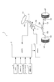
- FIG. 1 is a diagram illustrating a schematic configuration of a driving support system 1.
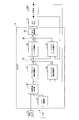
- FIG. It is a block diagram which shows the flow of the process which LKAECU performs. It is a figure which shows a target track
- the driving support system 1 of this embodiment is mounted on a vehicle, and includes a torque sensor 2, a motor 3, a camera 4, a vehicle speed sensor 5, a yaw rate sensor 6, a rudder angle sensor 7, and a lane keeping support electronic control device. 8 and an electric power steering electronic control unit 9.
- the lane keeping assist electronic control device 8 is referred to as a LKA ECU (Lane Keep Assist Electronic Control Unit) 8.
- the electric power steering electronic control unit 9 is referred to as EPSECU (Electric Power Steering Electronic Control Unit) 9.
- a vehicle equipped with the driving support system 1 is referred to as a host vehicle.
- the driving support system 1 performs control to avoid the departure when the host vehicle is about to depart from the lane.
- the handle 101 of the host vehicle is fixed to the first end of the steering shaft 102.
- the first end of the torque sensor 2 is connected to the second end of the steering shaft 102, and the second end of the torque sensor 2 is connected to the first end of the intermediate shaft 103.
- the torque sensor 2 is a sensor for detecting steering torque. Specifically, the torque sensor 2 has a torsion bar that connects the steering shaft 102 and the intermediate shaft 103, and detects the torque applied to the torsion bar based on the twist angle of the torsion bar.
- the motor 3 has a worm gear at the tip of its rotating shaft.
- the worm gear meshes with a worm wheel provided on the intermediate shaft 103. Thereby, the rotation of the motor 3 is transmitted to the intermediate shaft 103.
- the second end of the intermediate shaft 103 is connected to the steering gear box 104.
- the steering gear box 104 is configured by a gear mechanism including a rack and a pinion gear, and the rack teeth mesh with a pinion gear provided at the second end of the intermediate shaft 103. Therefore, when the driver turns the handle 101, the intermediate shaft 103 rotates (that is, the pinion gear rotates), thereby moving the rack to the left and right.
- Tie rods 105 are attached to both ends of the rack, and the tie rods 105 reciprocate left and right together with the rack. Thereby, the direction of the tire 107 is changed by pulling or pushing the knuckle arm 106 ahead of the tie rod 105.
- the camera 4 is attached to the front side of the host vehicle.
- the camera 4 repeatedly captures the road surface ahead of the host vehicle and outputs image data indicating the captured image.
- the vehicle speed sensor 5 detects the traveling speed of the host vehicle and outputs a vehicle speed signal indicating the detection result.
- the yaw rate sensor 6 detects the yaw rate of the host vehicle and outputs a yaw rate signal indicating the detection result.
- the steering angle sensor 7 detects the steering angle of the host vehicle, and outputs a steering angle signal indicating the detection result.
- the LKA ECU 8 is mainly configured by a known microcomputer including a CPU, a ROM, a RAM, an I / O, a bus line connecting these components, and the like.
- the CPU executes various processes based on a program stored in a non-transitory tangible storage medium such as a ROM while using the temporary storage function of the RAM.
- the LKA ECU 8 performs a calculation for avoiding the departure of the host vehicle from the lane based on information input from the torque sensor 2, the camera 4, the vehicle speed sensor 5, the yaw rate sensor 6, and the rudder angle sensor 7. Then, LKAECU 8 outputs a required torque ⁇ tgt indicating a torque required for the motor 3 to the EPS ECU 9 based on the calculation result.
- the EPS ECU 9 is configured around a known microcomputer including a CPU, ROM, RAM, I / O, a bus line connecting these components, and the like.
- the CPU executes various processes based on a program stored in a non-transitory tangible storage medium such as a ROM while using the temporary storage function of the RAM.
- the EPS ECU 9 applies a driving voltage corresponding to the required torque ⁇ tgt from the LKA ECU 8 to the motor 3 to cause the motor 3 to generate a force for steering both the tires 107.
- the LKA ECU 8 includes a lane recognition unit 21, a target trajectory generation unit 22, a feedforward steering angle calculation unit 23, a feedback steering angle calculation unit 24, a first adder 25, a feedforward torque calculation unit 26, a feedback A torque calculator 27, a second adder 28, and an output controller 29 are provided.
- the lane recognition unit 21 recognizes a white line dividing the left side and the right side of the traveling lane in which the host vehicle is traveling by performing image processing on the image data input from the camera 4.
- the lane recognition unit 21 calculates the lateral position, the lateral speed, and the departure angle of the host vehicle based on the position where the white line appears in the image data.
- the lateral position of the host vehicle is the position of the host vehicle along a direction perpendicular to the traveling direction of the travel lane in the travel lane.
- the lateral speed of the host vehicle is a moving speed of the host vehicle along a direction perpendicular to the traveling direction of the traveling lane.
- the departure angle is an angle at which the traveling direction of the host vehicle is inclined with respect to the traveling direction of the traveling lane.
- the target track generation unit 22 is based on the position of the white line recognized by the lane recognition unit 21, the lateral position and departure angle of the host vehicle calculated by the lane recognition unit 21, and the vehicle speed signal input from the vehicle speed sensor 5. It is determined whether or not the vehicle departs from the traveling lane. When the target track generation unit 22 determines that the vehicle departs from the travel lane, the target track generation unit 22 determines the target based on the lateral position and the departure angle calculated by the lane recognition unit 21 and the vehicle speed specified by the vehicle speed signal from the vehicle speed sensor 5. Start generating orbit data.
- the target track gradually changes the traveling direction of the host vehicle from the outside of the traveling lane toward the inside of the traveling lane so that the host vehicle finally travels in the center of the traveling lane.
- the target trajectory data includes a plurality of times based on the current time, a lateral position indicating a target trajectory corresponding to each of the plurality of times, a plurality of lateral velocities calculated corresponding to each of the plurality of lateral positions, A plurality of lateral accelerations calculated corresponding to each of the plurality of lateral positions.
- the target trajectory generation unit 22 outputs the lateral position, the lateral velocity, and the lateral acceleration that constitute the target trajectory data to the feedforward steering angle calculation unit 23 and the feedback steering angle calculation unit 24.
- the feedforward rudder angle calculation unit 23 calculates a rudder angle when the lateral acceleration output from the target trajectory generation unit 22 acts on the host vehicle based on an arithmetic expression indicating a relationship between the lateral acceleration and the rudder angle. and it outputs the steering angle as a feedforward steering angle [delta] FF.
- the feedback rudder angle calculation unit 24 performs feedback control so that the lateral position, lateral speed, and lateral acceleration of the host vehicle MC coincide with the lateral position, lateral speed, and lateral acceleration input from the target trajectory generation unit 22, respectively.
- the feedback steering angle ⁇ FB is calculated and output.
- the lateral position and the lateral speed of the host vehicle MC are calculated by the lane recognition unit 21. Further, the lateral acceleration of the host vehicle MC is calculated based on the yaw rate detected by the yaw rate sensor 6 and the vehicle speed detected by the vehicle speed sensor 5.
- the first adder 25 requests an addition value obtained by adding the feed forward steering angle ⁇ FF output from the feed forward steering angle calculation unit 23 and the feedback steering angle ⁇ FB output from the feedback steering angle calculation unit 24. Output as the steering angle ⁇ tgt .
- the feedforward torque calculation unit 26 converts the required steering angle ⁇ tgt output from the first adder 25 into torque, and outputs this torque as feedforward torque ⁇ FF .
- the relationship between the lateral acceleration and the torque (hereinafter referred to as the lateral acceleration-torque conversion relationship) is obtained in advance from vehicle specifications, and the feedforward torque calculator 26 calculates the relationship between the lateral acceleration-torque conversion relationship and the required steering angle ⁇ . on the basis of the lateral acceleration corresponding to tgt, it calculates a torque corresponding to the required steering angle [delta] tgt. Note that the lateral acceleration corresponding to the required steering angle ⁇ tgt is calculated based on an arithmetic expression indicating the relationship between the lateral acceleration and the steering angle.
- the feedback torque calculator 27 calculates a feedback torque ⁇ FB for feedback control so that the steering angle detected by the steering angle sensor 7 matches the required steering angle ⁇ tgt output from the first adder 25. Output.
- the second adder 28 adds an addition value obtained by adding the feed forward torque ⁇ FF output from the feed forward torque calculation unit 26 and the feedback torque ⁇ FB output from the feedback torque calculation unit 27 as a required torque ⁇ tgt. Output to the output control unit 29.
- the output control unit 29 controls the output of the required torque ⁇ tgt output from the second adder 28 to the EPS ECU 9.
- the EPS ECU 9 controls the motor 3 based on the required torque ⁇ tgt output from the output control unit 29.
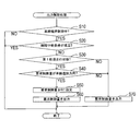
- the output control process is a process that is repeatedly executed during the operation of the LKA ECU 8.
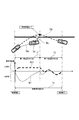
- the CPU of LKAECU 8 first determines in S10 whether or not lane keeping control is being executed, as shown in FIG. Specifically, when the target track generation unit 22 determines that the host vehicle departs from the travel lane and before the host vehicle returns to the travel lane (see period Tc in FIG. 5), the lane It is determined that maintenance control is being executed.
- a preset control interruption condition is that at least one of the following four interruption conditions is satisfied.
- the first interruption condition is that the lane recognition unit 21 cannot recognize a white line in the image data.
- the second interruption condition is that the vehicle speed is less than a predetermined interruption determination vehicle speed (for example, 40 km / m in the present embodiment).
- the third interruption condition is that the steering torque detected by the torque sensor 2 is equal to or greater than a predetermined interruption determination torque.
- the fourth interruption condition is that the direction indicator is operating.
- the first track traveling state is a state where the traveling direction of the host vehicle is in a direction deviating from the traveling lane (see period T1 in FIG. 5).
- the second track traveling state is a state in which the traveling direction of the host vehicle is in the direction of returning to the traveling lane (see period T2 in FIG. 5). Specifically, when the lateral acceleration calculated based on the yaw rate detected by the yaw rate sensor 6 and the vehicle speed detected by the vehicle speed sensor 5 is not 0, it is determined that the vehicle is in the first track traveling state.
- the vehicle is in the first track running state (S30: YES)
- the required control amount is the required torque ⁇ tgt output from the second adder 28. Specifically, as shown in FIG. 5, for example, when the host vehicle is moving so as to deviate to the left side of the traveling lane, the driver of the own vehicle moves to the right side in order to avoid the deviation. When the vehicle is steered, the vehicle is positioned on the right side of the target track TRt (see the actual track TRc in FIG. 5).
- the LKA ECU 8 performs request control for turning the host vehicle to the left in order to move the host vehicle to the left side (see the arrow ML in FIG. 5) so as to make the traveling track of the host vehicle coincide with the target track TRt.
- the amount is output (see arrow Qc and required control amount Rc1 in FIG. 5).
- the required control amount at this time is to steer the vehicle in a direction to deviate from the traveling lane.
- the requested control amount is set to 0 in S50 (see the requested control amount Rc2 in FIG. 5).
- the requested control amount set in S50 is output to the EPS ECU 9, and the output control process is temporarily terminated.
- the requested control amount is not one that steers in the departure direction (S40: NO)
- the process proceeds to S70.
- S30 when it is not in the first track running state (S30: NO), the process proceeds to S70.
- the required torque ⁇ tgt output from the second adder 28 is output to the EPS ECU 9 as a required control amount, and the output control process is temporarily terminated.
- the lane recognition unit 21 recognizes a travel lane in which the host vehicle travels.
- the target track generation unit 22 generates a target track for causing the host vehicle to travel so as to prevent the host vehicle from deviating from the recognized travel lane.
- the feedforward steering angle calculation unit 23, the feedback steering angle calculation unit 24, the first adder 25, the feedforward torque calculation unit 26, the feedback torque calculation unit 27, and the second adder 28 are arranged along the generated target trajectory.
- the required torque ⁇ tgt for controlling the steering of the host vehicle is calculated so that the host vehicle travels.
- the output control unit 29 is in the first track traveling state in which the traveling direction of the host vehicle is in a direction deviating from the traveling lane, and the calculated required torque ⁇ tgt is in the direction deviating from the traveling lane.
- the required torque ⁇ tgt is set to 0, which is a value that does not steer the vehicle in a direction deviating from the travel lane.
- the LKA ECU 8 can suppress giving the driver anxiety that the host vehicle is automatically steered in a direction deviating from the travel lane. For this reason, the LKA ECU 8 can reduce the driver's anxiety when avoiding deviation from the travel lane.
- the output control unit 29 of the LKA ECU 8 sets 0, which is a constant value, as a value that does not steer the host vehicle in a direction deviating from the traveling lane.
- the LKA ECU 8 can simplify the control for preventing the host vehicle from being steered in a direction deviating from the travel lane.
- the LKA ECU 8 is a lane keeping assist device according to the present invention.
- the lane recognition unit 21 is a traveling lane recognition unit in the present invention.
- the target trajectory generation unit 22 is a target trajectory setting means in the present invention.
- the feedforward steering angle calculation unit 23, the feedback steering angle calculation unit 24, the first adder 25, the feedforward torque calculation unit 26, the feedback torque calculation unit 27, and the second adder 28 are control amount calculation means in the present invention. is there. Furthermore, the output control unit 29 is a control amount setting means in the present invention.
- the traveling lane is a traveling lane in the present invention.
- the required torque ⁇ tgt is a steering control amount in the present invention.
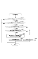
- the driving support system 1 of the second embodiment is the same as that of the first embodiment except that the output control process is changed.
- the output control process of the second embodiment is the same as that of the first embodiment except that S55 is executed instead of S50.
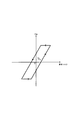
- the hysteresis torque Th is the maximum value of the required torque ⁇ tgt that maintains the steering angle at 0 when the steering angle is 0. That is, when the required torque ⁇ tgt exceeds the hysteresis torque Th in the departure avoidance direction, the host vehicle can be steered in the departure avoidance direction.
- the output control unit 29 of the LKA ECU 8 requests that the steering angle of the host vehicle be maintained at 0 when the steering angle of the host vehicle is 0 as a constant value that does not steer the host vehicle in a direction that deviates from the travel lane.
- a hysteresis torque Th that is the maximum value of the torque ⁇ tgt is set.
- the hysteresis torque Th is the maximum value of the steering control amount at which the steering angle in the present invention is maintained at zero.
- the LKA ECU 8 calculates the required torque ⁇ tgt and outputs the EPS ECU 9, but the steering control amount for controlling the steering of the host vehicle is not limited to this.
- the required control amount is set to 0 or the hysteresis torque Th in the departure avoidance direction.
- the present invention is not limited to this.
- the functions of one component in the above embodiment may be distributed as a plurality of components, or the functions of a plurality of components may be integrated into one component.
- at least a part of the configuration of the above embodiment may be replaced with a known configuration having the same function.
- at least a part of the configuration of the above embodiment may be added to or replaced with the configuration of the other embodiment.
- all the aspects included in the technical idea specified only by the wording described in the claim are embodiment of this invention.
- Driving support system 8 ... LKAECU DESCRIPTION OF SYMBOLS 21 ... Lane recognition part 22 ... Target track
Landscapes
- Engineering & Computer Science (AREA)
- Chemical & Material Sciences (AREA)
- Combustion & Propulsion (AREA)
- Transportation (AREA)
- Mechanical Engineering (AREA)
- Physics & Mathematics (AREA)
- General Physics & Mathematics (AREA)
- Multimedia (AREA)
- Theoretical Computer Science (AREA)
- Steering Control In Accordance With Driving Conditions (AREA)
Priority Applications (1)
| Application Number | Priority Date | Filing Date | Title |
|---|---|---|---|
| US15/739,133 US10538270B2 (en) | 2015-06-26 | 2016-06-22 | Lane keep assist device |
Applications Claiming Priority (2)
| Application Number | Priority Date | Filing Date | Title |
|---|---|---|---|
| JP2015-128886 | 2015-06-26 | ||
| JP2015128886A JP2017013519A (ja) | 2015-06-26 | 2015-06-26 | 車線維持支援装置 |
Publications (1)
| Publication Number | Publication Date |
|---|---|
| WO2016208627A1 true WO2016208627A1 (ja) | 2016-12-29 |
Family
ID=57586499
Family Applications (1)
| Application Number | Title | Priority Date | Filing Date |
|---|---|---|---|
| PCT/JP2016/068525 Ceased WO2016208627A1 (ja) | 2015-06-26 | 2016-06-22 | 車線維持支援装置 |
Country Status (3)
| Country | Link |
|---|---|
| US (1) | US10538270B2 (enExample) |
| JP (1) | JP2017013519A (enExample) |
| WO (1) | WO2016208627A1 (enExample) |
Cited By (1)
| Publication number | Priority date | Publication date | Assignee | Title |
|---|---|---|---|---|
| CN114179904A (zh) * | 2017-04-14 | 2022-03-15 | 日产自动车株式会社 | 车辆控制方法及车辆控制装置 |
Families Citing this family (5)
| Publication number | Priority date | Publication date | Assignee | Title |
|---|---|---|---|---|
| JP6524943B2 (ja) * | 2016-03-17 | 2019-06-05 | 株式会社デンソー | 走行支援装置 |
| US10248124B2 (en) * | 2016-07-21 | 2019-04-02 | Mobileye Vision Technologies, Inc. | Localizing vehicle navigation using lane measurements |
| JP2020075665A (ja) * | 2018-11-09 | 2020-05-21 | トヨタ自動車株式会社 | 車両走行制御装置 |
| JP7310272B2 (ja) * | 2019-04-25 | 2023-07-19 | 株式会社アドヴィックス | 車両の制御装置 |
| CN111645755B (zh) * | 2020-05-18 | 2021-10-01 | 长城汽车股份有限公司 | 一种控制方法和装置 |
Citations (1)
| Publication number | Priority date | Publication date | Assignee | Title |
|---|---|---|---|---|
| JP2013252862A (ja) * | 2013-09-27 | 2013-12-19 | Mitsubishi Motors Corp | 車線逸脱防止装置 |
Family Cites Families (3)
| Publication number | Priority date | Publication date | Assignee | Title |
|---|---|---|---|---|
| JP4867313B2 (ja) * | 2004-12-27 | 2012-02-01 | 日産自動車株式会社 | 車線逸脱防止装置 |
| EP2103500B1 (en) * | 2005-12-27 | 2010-12-22 | Honda Motor Co., Ltd. | Vehicle and steering control device for vehicle |
| JP6541216B2 (ja) * | 2015-03-20 | 2019-07-10 | 株式会社Subaru | 車両の車線逸脱防止制御装置 |
-
2015
- 2015-06-26 JP JP2015128886A patent/JP2017013519A/ja active Pending
-
2016
- 2016-06-22 US US15/739,133 patent/US10538270B2/en active Active
- 2016-06-22 WO PCT/JP2016/068525 patent/WO2016208627A1/ja not_active Ceased
Patent Citations (1)
| Publication number | Priority date | Publication date | Assignee | Title |
|---|---|---|---|---|
| JP2013252862A (ja) * | 2013-09-27 | 2013-12-19 | Mitsubishi Motors Corp | 車線逸脱防止装置 |
Cited By (2)
| Publication number | Priority date | Publication date | Assignee | Title |
|---|---|---|---|---|
| CN114179904A (zh) * | 2017-04-14 | 2022-03-15 | 日产自动车株式会社 | 车辆控制方法及车辆控制装置 |
| CN114179904B (zh) * | 2017-04-14 | 2023-08-01 | 日产自动车株式会社 | 车辆控制方法及车辆控制装置 |
Also Published As
| Publication number | Publication date |
|---|---|
| JP2017013519A (ja) | 2017-01-19 |
| US10538270B2 (en) | 2020-01-21 |
| US20180154937A1 (en) | 2018-06-07 |
Similar Documents
| Publication | Publication Date | Title |
|---|---|---|
| JP6332167B2 (ja) | 車線維持支援装置 | |
| EP1862374B1 (en) | Steering control device for vehicles | |
| JP6489135B2 (ja) | 車両の運転支援装置 | |
| CN106494497B (zh) | 车辆的操舵反力控制装置 | |
| CN107697153B (zh) | 作动器控制装置 | |
| CN106428210B (zh) | 车道维持辅助装置 | |
| JP6056975B2 (ja) | 車両用操舵制御装置および車両用操舵制御方法 | |
| WO2016208627A1 (ja) | 車線維持支援装置 | |
| CN113165642A (zh) | 转向操作装置及转向操作装置中的电动机控制方法 | |
| JP7099892B2 (ja) | 操舵制御装置 | |
| US9988081B2 (en) | Steering system | |
| JP6074976B2 (ja) | 車線維持支援装置 | |
| JP2018111460A (ja) | 車両の運転支援装置 | |
| JP2018103713A (ja) | 車両走行制御装置及び自動運転制御方法 | |
| JP2018103732A (ja) | 車両走行制御装置及び自動運転制御方法 | |
| CN107176201B (zh) | 转向操纵控制装置 | |
| JP5525357B2 (ja) | サーボ制御装置 | |
| JP2015151048A (ja) | 車両用軌跡制御装置 | |
| JP2017001625A (ja) | 車両用操舵装置 | |
| JP2017189994A (ja) | ステアリング制御装置 | |
| JP5735895B2 (ja) | 操舵支援装置 | |
| JP6566246B2 (ja) | 操舵支援装置 | |
| JP2010158987A (ja) | 車両用転舵制御装置 | |
| JP2018012473A (ja) | 操舵支援装置 | |
| JP2018114934A (ja) | 車両用制御装置 |
Legal Events
| Date | Code | Title | Description |
|---|---|---|---|
| 121 | Ep: the epo has been informed by wipo that ep was designated in this application |
Ref document number: 16814397 Country of ref document: EP Kind code of ref document: A1 |
|
| WWE | Wipo information: entry into national phase |
Ref document number: 15739133 Country of ref document: US |
|
| NENP | Non-entry into the national phase |
Ref country code: DE |
|
| 122 | Ep: pct application non-entry in european phase |
Ref document number: 16814397 Country of ref document: EP Kind code of ref document: A1 |