WO2016208627A1 - Lane keeping assistance device - Google Patents
Lane keeping assistance device Download PDFInfo
- Publication number
- WO2016208627A1 WO2016208627A1 PCT/JP2016/068525 JP2016068525W WO2016208627A1 WO 2016208627 A1 WO2016208627 A1 WO 2016208627A1 JP 2016068525 W JP2016068525 W JP 2016068525W WO 2016208627 A1 WO2016208627 A1 WO 2016208627A1
- Authority
- WO
- WIPO (PCT)
- Prior art keywords
- host vehicle
- lane
- vehicle
- steering
- torque
- Prior art date
Links
Images


Classifications
-
- B—PERFORMING OPERATIONS; TRANSPORTING
- B62—LAND VEHICLES FOR TRAVELLING OTHERWISE THAN ON RAILS
- B62D—MOTOR VEHICLES; TRAILERS
- B62D15/00—Steering not otherwise provided for
- B62D15/02—Steering position indicators ; Steering position determination; Steering aids
- B62D15/025—Active steering aids, e.g. helping the driver by actively influencing the steering system after environment evaluation
-
- B—PERFORMING OPERATIONS; TRANSPORTING
- B62—LAND VEHICLES FOR TRAVELLING OTHERWISE THAN ON RAILS
- B62D—MOTOR VEHICLES; TRAILERS
- B62D6/00—Arrangements for automatically controlling steering depending on driving conditions sensed and responded to, e.g. control circuits
- B62D6/08—Arrangements for automatically controlling steering depending on driving conditions sensed and responded to, e.g. control circuits responsive only to driver input torque
- B62D6/10—Arrangements for automatically controlling steering depending on driving conditions sensed and responded to, e.g. control circuits responsive only to driver input torque characterised by means for sensing or determining torque
-
- G—PHYSICS
- G06—COMPUTING; CALCULATING OR COUNTING
- G06V—IMAGE OR VIDEO RECOGNITION OR UNDERSTANDING
- G06V20/00—Scenes; Scene-specific elements
- G06V20/50—Context or environment of the image
- G06V20/56—Context or environment of the image exterior to a vehicle by using sensors mounted on the vehicle
- G06V20/588—Recognition of the road, e.g. of lane markings; Recognition of the vehicle driving pattern in relation to the road
Definitions
- the present invention relates to a lane keeping support device that maintains a state in which a vehicle does not deviate from a traveling lane.
- a lane keeping assist device that controls steering of a vehicle so that the vehicle does not deviate from the traveling lane is known (see, for example, Patent Document 1).
- This device sets a target track on which the host vehicle should travel in order to return to the driving lane when it is determined that the host vehicle tends to deviate from the driving lane.
- the driver of the own vehicle performs steering in a direction that avoids the departure from the traveling lane of the own vehicle.
- a situation is assumed in which the host vehicle is positioned inside the target track in the travel lane.
- the lane keeping assist device performs control for steering the host vehicle in a direction deviating from the traveling lane. For this reason, in a situation where the host vehicle is about to depart from the traveling lane, there is a risk of giving the driver an anxiety that the own vehicle is automatically steered in a direction deviating from the traveling lane.
- the present invention has been made in view of these problems, and an object of the present invention is to provide a technique for reducing a driver's anxiety when avoiding deviation from a driving lane.
- the lane keeping assist device of the present invention made to achieve the above object includes a traveling lane recognition means, a target track setting means, a control amount calculation means, and a control amount setting means.
- the travel lane recognition means recognizes the travel lane in which the host vehicle travels.
- the target trajectory setting means sets a target trajectory that is a trajectory on which the host vehicle travels so as to prevent the host vehicle from deviating from the travel lane recognized by the travel lane recognition means.
- the control amount calculation unit calculates a steering control amount for controlling the steering of the host vehicle so that the host vehicle travels along the target track set by the target track setting unit.
- the control amount setting means is while the traveling direction of the host vehicle is in a direction deviating from the traveling lane, and the steering control amount calculated by the control amount calculating unit is deviating from the traveling lane. Is set to a deviation prohibition value in which the host vehicle is not steered in a direction deviating from the traveling lane.
- the driver of the host vehicle performs steering in a direction that avoids the departure from the driving lane, so that the host vehicle is inward of the target track in the driving lane. Even if the vehicle is in a position, the steering control amount for steering the host vehicle in a direction deviating from the traveling lane is not output. Thereby, the lane keeping assist device of the present invention can suppress giving the driver anxiety that the host vehicle is automatically steered in a direction deviating from the traveling lane. For this reason, the lane keeping assist device of the present invention can reduce the driver's anxiety when avoiding deviation from the traveling lane.
- FIG. 1 is a diagram illustrating a schematic configuration of a driving support system 1.
- FIG. It is a block diagram which shows the flow of the process which LKAECU performs. It is a figure which shows a target track
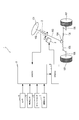
- the driving support system 1 of this embodiment is mounted on a vehicle, and includes a torque sensor 2, a motor 3, a camera 4, a vehicle speed sensor 5, a yaw rate sensor 6, a rudder angle sensor 7, and a lane keeping support electronic control device. 8 and an electric power steering electronic control unit 9.
- the lane keeping assist electronic control device 8 is referred to as a LKA ECU (Lane Keep Assist Electronic Control Unit) 8.
- the electric power steering electronic control unit 9 is referred to as EPSECU (Electric Power Steering Electronic Control Unit) 9.
- a vehicle equipped with the driving support system 1 is referred to as a host vehicle.
- the driving support system 1 performs control to avoid the departure when the host vehicle is about to depart from the lane.
- the handle 101 of the host vehicle is fixed to the first end of the steering shaft 102.
- the first end of the torque sensor 2 is connected to the second end of the steering shaft 102, and the second end of the torque sensor 2 is connected to the first end of the intermediate shaft 103.
- the torque sensor 2 is a sensor for detecting steering torque. Specifically, the torque sensor 2 has a torsion bar that connects the steering shaft 102 and the intermediate shaft 103, and detects the torque applied to the torsion bar based on the twist angle of the torsion bar.
- the motor 3 has a worm gear at the tip of its rotating shaft.
- the worm gear meshes with a worm wheel provided on the intermediate shaft 103. Thereby, the rotation of the motor 3 is transmitted to the intermediate shaft 103.
- the second end of the intermediate shaft 103 is connected to the steering gear box 104.
- the steering gear box 104 is configured by a gear mechanism including a rack and a pinion gear, and the rack teeth mesh with a pinion gear provided at the second end of the intermediate shaft 103. Therefore, when the driver turns the handle 101, the intermediate shaft 103 rotates (that is, the pinion gear rotates), thereby moving the rack to the left and right.
- Tie rods 105 are attached to both ends of the rack, and the tie rods 105 reciprocate left and right together with the rack. Thereby, the direction of the tire 107 is changed by pulling or pushing the knuckle arm 106 ahead of the tie rod 105.
- the camera 4 is attached to the front side of the host vehicle.
- the camera 4 repeatedly captures the road surface ahead of the host vehicle and outputs image data indicating the captured image.
- the vehicle speed sensor 5 detects the traveling speed of the host vehicle and outputs a vehicle speed signal indicating the detection result.
- the yaw rate sensor 6 detects the yaw rate of the host vehicle and outputs a yaw rate signal indicating the detection result.
- the steering angle sensor 7 detects the steering angle of the host vehicle, and outputs a steering angle signal indicating the detection result.
- the LKA ECU 8 is mainly configured by a known microcomputer including a CPU, a ROM, a RAM, an I / O, a bus line connecting these components, and the like.
- the CPU executes various processes based on a program stored in a non-transitory tangible storage medium such as a ROM while using the temporary storage function of the RAM.
- the LKA ECU 8 performs a calculation for avoiding the departure of the host vehicle from the lane based on information input from the torque sensor 2, the camera 4, the vehicle speed sensor 5, the yaw rate sensor 6, and the rudder angle sensor 7. Then, LKAECU 8 outputs a required torque ⁇ tgt indicating a torque required for the motor 3 to the EPS ECU 9 based on the calculation result.
- the EPS ECU 9 is configured around a known microcomputer including a CPU, ROM, RAM, I / O, a bus line connecting these components, and the like.
- the CPU executes various processes based on a program stored in a non-transitory tangible storage medium such as a ROM while using the temporary storage function of the RAM.
- the EPS ECU 9 applies a driving voltage corresponding to the required torque ⁇ tgt from the LKA ECU 8 to the motor 3 to cause the motor 3 to generate a force for steering both the tires 107.
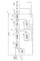
- the LKA ECU 8 includes a lane recognition unit 21, a target trajectory generation unit 22, a feedforward steering angle calculation unit 23, a feedback steering angle calculation unit 24, a first adder 25, a feedforward torque calculation unit 26, a feedback A torque calculator 27, a second adder 28, and an output controller 29 are provided.
- the lane recognition unit 21 recognizes a white line dividing the left side and the right side of the traveling lane in which the host vehicle is traveling by performing image processing on the image data input from the camera 4.
- the lane recognition unit 21 calculates the lateral position, the lateral speed, and the departure angle of the host vehicle based on the position where the white line appears in the image data.
- the lateral position of the host vehicle is the position of the host vehicle along a direction perpendicular to the traveling direction of the travel lane in the travel lane.
- the lateral speed of the host vehicle is a moving speed of the host vehicle along a direction perpendicular to the traveling direction of the traveling lane.
- the departure angle is an angle at which the traveling direction of the host vehicle is inclined with respect to the traveling direction of the traveling lane.
- the target track generation unit 22 is based on the position of the white line recognized by the lane recognition unit 21, the lateral position and departure angle of the host vehicle calculated by the lane recognition unit 21, and the vehicle speed signal input from the vehicle speed sensor 5. It is determined whether or not the vehicle departs from the traveling lane. When the target track generation unit 22 determines that the vehicle departs from the travel lane, the target track generation unit 22 determines the target based on the lateral position and the departure angle calculated by the lane recognition unit 21 and the vehicle speed specified by the vehicle speed signal from the vehicle speed sensor 5. Start generating orbit data.
- the target track gradually changes the traveling direction of the host vehicle from the outside of the traveling lane toward the inside of the traveling lane so that the host vehicle finally travels in the center of the traveling lane.
- the target trajectory data includes a plurality of times based on the current time, a lateral position indicating a target trajectory corresponding to each of the plurality of times, a plurality of lateral velocities calculated corresponding to each of the plurality of lateral positions, A plurality of lateral accelerations calculated corresponding to each of the plurality of lateral positions.
- the target trajectory generation unit 22 outputs the lateral position, the lateral velocity, and the lateral acceleration that constitute the target trajectory data to the feedforward steering angle calculation unit 23 and the feedback steering angle calculation unit 24.
- the feedforward rudder angle calculation unit 23 calculates a rudder angle when the lateral acceleration output from the target trajectory generation unit 22 acts on the host vehicle based on an arithmetic expression indicating a relationship between the lateral acceleration and the rudder angle. and it outputs the steering angle as a feedforward steering angle [delta] FF.
- the feedback rudder angle calculation unit 24 performs feedback control so that the lateral position, lateral speed, and lateral acceleration of the host vehicle MC coincide with the lateral position, lateral speed, and lateral acceleration input from the target trajectory generation unit 22, respectively.
- the feedback steering angle ⁇ FB is calculated and output.
- the lateral position and the lateral speed of the host vehicle MC are calculated by the lane recognition unit 21. Further, the lateral acceleration of the host vehicle MC is calculated based on the yaw rate detected by the yaw rate sensor 6 and the vehicle speed detected by the vehicle speed sensor 5.
- the first adder 25 requests an addition value obtained by adding the feed forward steering angle ⁇ FF output from the feed forward steering angle calculation unit 23 and the feedback steering angle ⁇ FB output from the feedback steering angle calculation unit 24. Output as the steering angle ⁇ tgt .
- the feedforward torque calculation unit 26 converts the required steering angle ⁇ tgt output from the first adder 25 into torque, and outputs this torque as feedforward torque ⁇ FF .
- the relationship between the lateral acceleration and the torque (hereinafter referred to as the lateral acceleration-torque conversion relationship) is obtained in advance from vehicle specifications, and the feedforward torque calculator 26 calculates the relationship between the lateral acceleration-torque conversion relationship and the required steering angle ⁇ . on the basis of the lateral acceleration corresponding to tgt, it calculates a torque corresponding to the required steering angle [delta] tgt. Note that the lateral acceleration corresponding to the required steering angle ⁇ tgt is calculated based on an arithmetic expression indicating the relationship between the lateral acceleration and the steering angle.
- the feedback torque calculator 27 calculates a feedback torque ⁇ FB for feedback control so that the steering angle detected by the steering angle sensor 7 matches the required steering angle ⁇ tgt output from the first adder 25. Output.
- the second adder 28 adds an addition value obtained by adding the feed forward torque ⁇ FF output from the feed forward torque calculation unit 26 and the feedback torque ⁇ FB output from the feedback torque calculation unit 27 as a required torque ⁇ tgt. Output to the output control unit 29.
- the output control unit 29 controls the output of the required torque ⁇ tgt output from the second adder 28 to the EPS ECU 9.
- the EPS ECU 9 controls the motor 3 based on the required torque ⁇ tgt output from the output control unit 29.
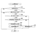
- the output control process is a process that is repeatedly executed during the operation of the LKA ECU 8.
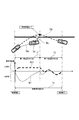
- the CPU of LKAECU 8 first determines in S10 whether or not lane keeping control is being executed, as shown in FIG. Specifically, when the target track generation unit 22 determines that the host vehicle departs from the travel lane and before the host vehicle returns to the travel lane (see period Tc in FIG. 5), the lane It is determined that maintenance control is being executed.
- a preset control interruption condition is that at least one of the following four interruption conditions is satisfied.
- the first interruption condition is that the lane recognition unit 21 cannot recognize a white line in the image data.
- the second interruption condition is that the vehicle speed is less than a predetermined interruption determination vehicle speed (for example, 40 km / m in the present embodiment).
- the third interruption condition is that the steering torque detected by the torque sensor 2 is equal to or greater than a predetermined interruption determination torque.
- the fourth interruption condition is that the direction indicator is operating.
- the first track traveling state is a state where the traveling direction of the host vehicle is in a direction deviating from the traveling lane (see period T1 in FIG. 5).
- the second track traveling state is a state in which the traveling direction of the host vehicle is in the direction of returning to the traveling lane (see period T2 in FIG. 5). Specifically, when the lateral acceleration calculated based on the yaw rate detected by the yaw rate sensor 6 and the vehicle speed detected by the vehicle speed sensor 5 is not 0, it is determined that the vehicle is in the first track traveling state.
- the vehicle is in the first track running state (S30: YES)
- the required control amount is the required torque ⁇ tgt output from the second adder 28. Specifically, as shown in FIG. 5, for example, when the host vehicle is moving so as to deviate to the left side of the traveling lane, the driver of the own vehicle moves to the right side in order to avoid the deviation. When the vehicle is steered, the vehicle is positioned on the right side of the target track TRt (see the actual track TRc in FIG. 5).
- the LKA ECU 8 performs request control for turning the host vehicle to the left in order to move the host vehicle to the left side (see the arrow ML in FIG. 5) so as to make the traveling track of the host vehicle coincide with the target track TRt.
- the amount is output (see arrow Qc and required control amount Rc1 in FIG. 5).
- the required control amount at this time is to steer the vehicle in a direction to deviate from the traveling lane.
- the requested control amount is set to 0 in S50 (see the requested control amount Rc2 in FIG. 5).
- the requested control amount set in S50 is output to the EPS ECU 9, and the output control process is temporarily terminated.
- the requested control amount is not one that steers in the departure direction (S40: NO)
- the process proceeds to S70.
- S30 when it is not in the first track running state (S30: NO), the process proceeds to S70.
- the required torque ⁇ tgt output from the second adder 28 is output to the EPS ECU 9 as a required control amount, and the output control process is temporarily terminated.
- the lane recognition unit 21 recognizes a travel lane in which the host vehicle travels.
- the target track generation unit 22 generates a target track for causing the host vehicle to travel so as to prevent the host vehicle from deviating from the recognized travel lane.
- the feedforward steering angle calculation unit 23, the feedback steering angle calculation unit 24, the first adder 25, the feedforward torque calculation unit 26, the feedback torque calculation unit 27, and the second adder 28 are arranged along the generated target trajectory.
- the required torque ⁇ tgt for controlling the steering of the host vehicle is calculated so that the host vehicle travels.
- the output control unit 29 is in the first track traveling state in which the traveling direction of the host vehicle is in a direction deviating from the traveling lane, and the calculated required torque ⁇ tgt is in the direction deviating from the traveling lane.
- the required torque ⁇ tgt is set to 0, which is a value that does not steer the vehicle in a direction deviating from the travel lane.
- the LKA ECU 8 can suppress giving the driver anxiety that the host vehicle is automatically steered in a direction deviating from the travel lane. For this reason, the LKA ECU 8 can reduce the driver's anxiety when avoiding deviation from the travel lane.
- the output control unit 29 of the LKA ECU 8 sets 0, which is a constant value, as a value that does not steer the host vehicle in a direction deviating from the traveling lane.
- the LKA ECU 8 can simplify the control for preventing the host vehicle from being steered in a direction deviating from the travel lane.
- the LKA ECU 8 is a lane keeping assist device according to the present invention.
- the lane recognition unit 21 is a traveling lane recognition unit in the present invention.
- the target trajectory generation unit 22 is a target trajectory setting means in the present invention.
- the feedforward steering angle calculation unit 23, the feedback steering angle calculation unit 24, the first adder 25, the feedforward torque calculation unit 26, the feedback torque calculation unit 27, and the second adder 28 are control amount calculation means in the present invention. is there. Furthermore, the output control unit 29 is a control amount setting means in the present invention.
- the traveling lane is a traveling lane in the present invention.
- the required torque ⁇ tgt is a steering control amount in the present invention.
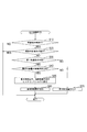
- the driving support system 1 of the second embodiment is the same as that of the first embodiment except that the output control process is changed.
- the output control process of the second embodiment is the same as that of the first embodiment except that S55 is executed instead of S50.
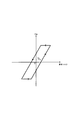
- the hysteresis torque Th is the maximum value of the required torque ⁇ tgt that maintains the steering angle at 0 when the steering angle is 0. That is, when the required torque ⁇ tgt exceeds the hysteresis torque Th in the departure avoidance direction, the host vehicle can be steered in the departure avoidance direction.
- the output control unit 29 of the LKA ECU 8 requests that the steering angle of the host vehicle be maintained at 0 when the steering angle of the host vehicle is 0 as a constant value that does not steer the host vehicle in a direction that deviates from the travel lane.
- a hysteresis torque Th that is the maximum value of the torque ⁇ tgt is set.
- the hysteresis torque Th is the maximum value of the steering control amount at which the steering angle in the present invention is maintained at zero.
- the LKA ECU 8 calculates the required torque ⁇ tgt and outputs the EPS ECU 9, but the steering control amount for controlling the steering of the host vehicle is not limited to this.
- the required control amount is set to 0 or the hysteresis torque Th in the departure avoidance direction.
- the present invention is not limited to this.
- the functions of one component in the above embodiment may be distributed as a plurality of components, or the functions of a plurality of components may be integrated into one component.
- at least a part of the configuration of the above embodiment may be replaced with a known configuration having the same function.
- at least a part of the configuration of the above embodiment may be added to or replaced with the configuration of the other embodiment.
- all the aspects included in the technical idea specified only by the wording described in the claim are embodiment of this invention.
- Driving support system 8 ... LKAECU DESCRIPTION OF SYMBOLS 21 ... Lane recognition part 22 ... Target track
Abstract
In a LKAECU 8, a lane recognition unit 21 recognizes a travel lane along which a vehicle is traveling. A target trajectory generation unit 22 generates a target trajectory for causing the vehicle to travel such that departure of the vehicle from the travel lane is inhibited. A feedforward steering angle calculation unit 23, a feedback steering angle calculation unit 24, first adders 25, 28, a feedforward torque calculation unit 26, and a feedback torque calculation unit 27 calculate a request torque τtgt for controlling the steering of the vehicle such that the vehicle travels along the target trajectory. In cases when the travel direction of the vehicle is oriented in a direction departing from the travel lane, and the request torque τtgt is steering the vehicle in the direction departing from the travel lane, an output control unit 29 sets the request torque τtgt at a value at which the vehicle is not steered in the direction departing from the travel lane.
Description
本発明は、車両が走行車線から逸脱しない状態を維持する車線維持支援装置に関する。
The present invention relates to a lane keeping support device that maintains a state in which a vehicle does not deviate from a traveling lane.
車両が走行車線から逸脱しないように車両の操舵を制御する車線維持支援装置が知られている(例えば、特許文献1を参照)。この装置は、自車両が走行車線から逸脱する傾向にあると判定された場合に、自車両が走行車線に復帰するために自車両が走行するべき目標軌道を設定するもの
A lane keeping assist device that controls steering of a vehicle so that the vehicle does not deviate from the traveling lane is known (see, for example, Patent Document 1). This device sets a target track on which the host vehicle should travel in order to return to the driving lane when it is determined that the host vehicle tends to deviate from the driving lane.
しかし、自車両が走行車線から逸脱する傾向にあると判定されて目標軌道が設定された後に、自車両の走行車線からの逸脱を回避する方向への操舵を自車両の運転者が行うと、走行車線内において自車両が目標軌道よりも内側に位置することになる状況が想定される。このような状況において自車両を目標軌道に追従させる制御を行うと、車線維持支援装置は、走行車線から逸脱する方向へ自車両を操舵する制御を行うことになる。このため、自車両が走行車線から逸脱しようとしている状況において、走行車線から逸脱する方向へ自車両が自動的に操舵されていくという不安感を運転者に与えてしまうおそれがあった。
However, when it is determined that the host vehicle tends to deviate from the traveling lane and the target track is set, the driver of the own vehicle performs steering in a direction that avoids the departure from the traveling lane of the own vehicle. A situation is assumed in which the host vehicle is positioned inside the target track in the travel lane. In such a situation, when the control for causing the host vehicle to follow the target track is performed, the lane keeping assist device performs control for steering the host vehicle in a direction deviating from the traveling lane. For this reason, in a situation where the host vehicle is about to depart from the traveling lane, there is a risk of giving the driver an anxiety that the own vehicle is automatically steered in a direction deviating from the traveling lane.
本発明は、こうした問題に鑑みてなされたものであり、走行車線からの逸脱を回避する場合における運転者の不安感を低減する技術を提供することを目的とする。
The present invention has been made in view of these problems, and an object of the present invention is to provide a technique for reducing a driver's anxiety when avoiding deviation from a driving lane.
上記目的を達成するためになされた本発明の車線維持支援装置は、走行車線認識手段と、目標軌道設定手段と、制御量算出手段と、制御量設定手段とを備える。
走行車線認識手段は、自車両が走行する走行車線を認識する。目標軌道設定手段は、走行車線認識手段により認識された走行車線から自車両が逸脱するのを抑制するように自車両を走行させる軌道である目標軌道を設定する。制御量算出手段は、目標軌道設定手段により設定された目標軌道に沿って自車両が走行するように自車両の操舵を制御するための操舵制御量を算出する。制御量設定手段は、自車両の進行方向が走行車線から逸脱する方向に向いている間であり、且つ、制御量算出手段により算出された操舵制御量が、走行車線から逸脱する方向へ自車両を操舵するものである場合に、操舵制御量を、走行車線から逸脱する方向へ自車両を操舵しない逸脱禁止値に設定する。 The lane keeping assist device of the present invention made to achieve the above object includes a traveling lane recognition means, a target track setting means, a control amount calculation means, and a control amount setting means.
The travel lane recognition means recognizes the travel lane in which the host vehicle travels. The target trajectory setting means sets a target trajectory that is a trajectory on which the host vehicle travels so as to prevent the host vehicle from deviating from the travel lane recognized by the travel lane recognition means. The control amount calculation unit calculates a steering control amount for controlling the steering of the host vehicle so that the host vehicle travels along the target track set by the target track setting unit. The control amount setting means is while the traveling direction of the host vehicle is in a direction deviating from the traveling lane, and the steering control amount calculated by the control amount calculating unit is deviating from the traveling lane. Is set to a deviation prohibition value in which the host vehicle is not steered in a direction deviating from the traveling lane.
このように構成された本発明の車線維持支援装置は、走行車線からの逸脱を回避する方向への操舵を自車両の運転者が行うことにより走行車線内において自車両が目標軌道よりも内側に位置する状況になったとしても、走行車線から逸脱する方向へ自車両を操舵する操舵制御量を出力しない。これにより、本発明の車線維持支援装置は、走行車線から逸脱する方向へ自車両が自動的に操舵されていくという不安感を運転者に与えるのを抑制することができる。このため、本発明の車線維持支援装置は、走行車線からの逸脱を回避する場合における運転者の不安感を低減することができる。
In the lane keeping assist device of the present invention configured as described above, the driver of the host vehicle performs steering in a direction that avoids the departure from the driving lane, so that the host vehicle is inward of the target track in the driving lane. Even if the vehicle is in a position, the steering control amount for steering the host vehicle in a direction deviating from the traveling lane is not output. Thereby, the lane keeping assist device of the present invention can suppress giving the driver anxiety that the host vehicle is automatically steered in a direction deviating from the traveling lane. For this reason, the lane keeping assist device of the present invention can reduce the driver's anxiety when avoiding deviation from the traveling lane.
(第1実施形態)
以下に本発明の第1実施形態を図面とともに説明する。
図1に示すように、本実施形態の走行支援システム1は車両に搭載され、トルクセンサ2、モータ3、カメラ4、車速センサ5、ヨーレートセンサ6、舵角センサ7、車線維持支援電子制御装置8および電動パワーステアリング電子制御装置9を備える。以下、車線維持支援電子制御装置8をLKAECU(Lane Keep Assist Electronic Control Unit)8という。また、電動パワーステアリング電子制御装置9をEPSECU(Electric Power Steering Electronic Control Unit)9という。さらに、走行支援システム1を搭載する車両を自車両という。 (First embodiment)
A first embodiment of the present invention will be described below with reference to the drawings.
As shown in FIG. 1, the driving support system 1 of this embodiment is mounted on a vehicle, and includes atorque sensor 2, a motor 3, a camera 4, a vehicle speed sensor 5, a yaw rate sensor 6, a rudder angle sensor 7, and a lane keeping support electronic control device. 8 and an electric power steering electronic control unit 9. Hereinafter, the lane keeping assist electronic control device 8 is referred to as a LKA ECU (Lane Keep Assist Electronic Control Unit) 8. The electric power steering electronic control unit 9 is referred to as EPSECU (Electric Power Steering Electronic Control Unit) 9. Furthermore, a vehicle equipped with the driving support system 1 is referred to as a host vehicle.
以下に本発明の第1実施形態を図面とともに説明する。
図1に示すように、本実施形態の走行支援システム1は車両に搭載され、トルクセンサ2、モータ3、カメラ4、車速センサ5、ヨーレートセンサ6、舵角センサ7、車線維持支援電子制御装置8および電動パワーステアリング電子制御装置9を備える。以下、車線維持支援電子制御装置8をLKAECU(Lane Keep Assist Electronic Control Unit)8という。また、電動パワーステアリング電子制御装置9をEPSECU(Electric Power Steering Electronic Control Unit)9という。さらに、走行支援システム1を搭載する車両を自車両という。 (First embodiment)
A first embodiment of the present invention will be described below with reference to the drawings.
As shown in FIG. 1, the driving support system 1 of this embodiment is mounted on a vehicle, and includes a
走行支援システム1は、自車両が車線から逸脱しそうになった場合にその逸脱を回避するための制御を行う。
自車両のハンドル101は、ステアリングシャフト102の第一端に固定される。トルクセンサ2の第一端はステアリングシャフト102の第二端に接続され、トルクセンサ2の第二端はインターミディエイトシャフト103の第一端に接続される。 The driving support system 1 performs control to avoid the departure when the host vehicle is about to depart from the lane.
Thehandle 101 of the host vehicle is fixed to the first end of the steering shaft 102. The first end of the torque sensor 2 is connected to the second end of the steering shaft 102, and the second end of the torque sensor 2 is connected to the first end of the intermediate shaft 103.
自車両のハンドル101は、ステアリングシャフト102の第一端に固定される。トルクセンサ2の第一端はステアリングシャフト102の第二端に接続され、トルクセンサ2の第二端はインターミディエイトシャフト103の第一端に接続される。 The driving support system 1 performs control to avoid the departure when the host vehicle is about to depart from the lane.
The
トルクセンサ2は、操舵トルクを検出するためのセンサである。具体的には、トルクセンサ2は、ステアリングシャフト102とインターミディエイトシャフト103とを連結するトーションバーを有し、このトーションバーのねじれ角に基づいてそのトーションバーに加えられているトルクを検出する。
The torque sensor 2 is a sensor for detecting steering torque. Specifically, the torque sensor 2 has a torsion bar that connects the steering shaft 102 and the intermediate shaft 103, and detects the torque applied to the torsion bar based on the twist angle of the torsion bar.
モータ3は、その回転軸の先端にウォームギアを備える。このウォームギアは、インターミディエイトシャフト103に設けられたウォームホイールと噛み合っている。これにより、モータ3の回転がインターミディエイトシャフト103に伝達される。
The motor 3 has a worm gear at the tip of its rotating shaft. The worm gear meshes with a worm wheel provided on the intermediate shaft 103. Thereby, the rotation of the motor 3 is transmitted to the intermediate shaft 103.
インターミディエイトシャフト103の第二端は、ステアリングギアボックス104に接続されている。ステアリングギアボックス104は、ラックとピニオンギアからなるギア機構にて構成されており、インターミディエイトシャフト103の第二端に設けられたピニオンギアに、ラックの歯が噛み合っている。そのため、運転者がハンドル101を回すと、インターミディエイトシャフト103が回転(すなわち、ピニオンギアが回転)し、これによりラックが左右に移動する。ラックの両端にはそれぞれタイロッド105が取り付けられており、ラックとともにタイロッド105が左右の往復運動を行う。これにより、タイロッド105がその先のナックルアーム106を引っ張ったり押したりすることで、タイヤ107の向きが変わる。
The second end of the intermediate shaft 103 is connected to the steering gear box 104. The steering gear box 104 is configured by a gear mechanism including a rack and a pinion gear, and the rack teeth mesh with a pinion gear provided at the second end of the intermediate shaft 103. Therefore, when the driver turns the handle 101, the intermediate shaft 103 rotates (that is, the pinion gear rotates), thereby moving the rack to the left and right. Tie rods 105 are attached to both ends of the rack, and the tie rods 105 reciprocate left and right together with the rack. Thereby, the direction of the tire 107 is changed by pulling or pushing the knuckle arm 106 ahead of the tie rod 105.
カメラ4は、詳細には図示しないが、自車両の前側に取り付けられている。このカメラ4は、自車両の前方の路面を繰り返し撮影し、その撮影画像を示す画像データを出力する。
車速センサ5は、自車両の走行速度を検出し、その検出結果を示す車速信号を出力する。ヨーレートセンサ6は、自車両のヨーレートを検出し、その検出結果を示すヨーレート信号を出力する。舵角センサ7は、自車両の舵角を検出し、その検出結果を示す舵角信号を出力する。 Although not shown in detail, thecamera 4 is attached to the front side of the host vehicle. The camera 4 repeatedly captures the road surface ahead of the host vehicle and outputs image data indicating the captured image.
Thevehicle speed sensor 5 detects the traveling speed of the host vehicle and outputs a vehicle speed signal indicating the detection result. The yaw rate sensor 6 detects the yaw rate of the host vehicle and outputs a yaw rate signal indicating the detection result. The steering angle sensor 7 detects the steering angle of the host vehicle, and outputs a steering angle signal indicating the detection result.
車速センサ5は、自車両の走行速度を検出し、その検出結果を示す車速信号を出力する。ヨーレートセンサ6は、自車両のヨーレートを検出し、その検出結果を示すヨーレート信号を出力する。舵角センサ7は、自車両の舵角を検出し、その検出結果を示す舵角信号を出力する。 Although not shown in detail, the
The
LKAECU8は、CPU、ROM、RAM、I/O及びこれらの構成を接続するバスラインなどからなる周知のマイクロコンピュータを中心に構成される。CPUは、RAMの一時記憶機能を利用しつつ、ROMなどの非遷移的実体的記録媒体(non-transitory tangible storage media)に記憶されているプログラムに基づいて各種処理を実行する。LKAECU8は、トルクセンサ2、カメラ4、車速センサ5、ヨーレートセンサ6および舵角センサ7から入力される情報に基づいて、自車両が車線から逸脱するのを回避するための演算を行う。そしてLKAECU8は、この演算結果に基づいて、モータ3へ要求するトルクを示す要求トルクτtgtをEPSECU9へ出力する。
The LKA ECU 8 is mainly configured by a known microcomputer including a CPU, a ROM, a RAM, an I / O, a bus line connecting these components, and the like. The CPU executes various processes based on a program stored in a non-transitory tangible storage medium such as a ROM while using the temporary storage function of the RAM. The LKA ECU 8 performs a calculation for avoiding the departure of the host vehicle from the lane based on information input from the torque sensor 2, the camera 4, the vehicle speed sensor 5, the yaw rate sensor 6, and the rudder angle sensor 7. Then, LKAECU 8 outputs a required torque τ tgt indicating a torque required for the motor 3 to the EPS ECU 9 based on the calculation result.
EPSECU9は、CPU、ROM、RAM、I/O及びこれらの構成を接続するバスラインなどからなる周知のマイクロコンピュータを中心に構成される。CPUは、RAMの一時記憶機能を利用しつつ、ROMなどの非遷移的実体的記録媒体(non-transitory tangible storage media)に記憶されているプログラムに基づいて各種処理を実行する。EPSECU9は、LKAECU8からの要求トルクτtgtに応じた駆動電圧をモータ3へ印加することにより、両タイヤ107を操舵するための力をモータ3に発生させる。
The EPS ECU 9 is configured around a known microcomputer including a CPU, ROM, RAM, I / O, a bus line connecting these components, and the like. The CPU executes various processes based on a program stored in a non-transitory tangible storage medium such as a ROM while using the temporary storage function of the RAM. The EPS ECU 9 applies a driving voltage corresponding to the required torque τ tgt from the LKA ECU 8 to the motor 3 to cause the motor 3 to generate a force for steering both the tires 107.
LKAECU8は、図2に示すように、レーン認識部21、目標軌道生成部22、フィードフォワード舵角演算部23、フィードバック舵角演算部24、第一加算器25、フィードフォワードトルク演算部26、フィードバックトルク演算部27、第二加算器28および出力制御部29を備える。
As shown in FIG. 2, the LKA ECU 8 includes a lane recognition unit 21, a target trajectory generation unit 22, a feedforward steering angle calculation unit 23, a feedback steering angle calculation unit 24, a first adder 25, a feedforward torque calculation unit 26, a feedback A torque calculator 27, a second adder 28, and an output controller 29 are provided.
レーン認識部21は、カメラ4から入力された画像データを画像処理することにより、自車両が走行している走行レーンの左側と右側とを区画する白線を認識する。そしてレーン認識部21は、画像データ内において白線が写っている位置に基づいて、自車両の横位置、横速度および逸脱角度を算出する。自車両の横位置は、走行レーン内において走行レーンの進行方向に対して垂直な方向に沿った自車両の位置である。自車両の横速度は、走行レーンの進行方向に対して垂直な方向に沿った自車両の移動速度である。逸脱角度は、走行レーンの進行方向に対して自車両の進行方向が傾いている角度である。
The lane recognition unit 21 recognizes a white line dividing the left side and the right side of the traveling lane in which the host vehicle is traveling by performing image processing on the image data input from the camera 4. The lane recognition unit 21 calculates the lateral position, the lateral speed, and the departure angle of the host vehicle based on the position where the white line appears in the image data. The lateral position of the host vehicle is the position of the host vehicle along a direction perpendicular to the traveling direction of the travel lane in the travel lane. The lateral speed of the host vehicle is a moving speed of the host vehicle along a direction perpendicular to the traveling direction of the traveling lane. The departure angle is an angle at which the traveling direction of the host vehicle is inclined with respect to the traveling direction of the traveling lane.
目標軌道生成部22は、レーン認識部21が認識した白線の位置と、レーン認識部21が算出した自車両の横位置および逸脱角度と、車速センサ5から入力される車速信号とに基づいて、自車両が走行レーンから逸脱するか否かを判断する。そして目標軌道生成部22は、走行レーンから逸脱すると判断した場合に、レーン認識部21が算出した横位置および逸脱角度と、車速センサ5からの車速信号により特定される車速とに基づいて、目標軌道データの生成を開始する。
The target track generation unit 22 is based on the position of the white line recognized by the lane recognition unit 21, the lateral position and departure angle of the host vehicle calculated by the lane recognition unit 21, and the vehicle speed signal input from the vehicle speed sensor 5. It is determined whether or not the vehicle departs from the traveling lane. When the target track generation unit 22 determines that the vehicle departs from the travel lane, the target track generation unit 22 determines the target based on the lateral position and the departure angle calculated by the lane recognition unit 21 and the vehicle speed specified by the vehicle speed signal from the vehicle speed sensor 5. Start generating orbit data.
目標軌道は、図3に示すように、自車両の進行方向を走行レーンの外側から走行レーンの内側に向かうように徐々に変化させ、最終的に走行レーンの中央を自車両が走行するように設定される軌道である。目標軌道データは、現時点を基点とした複数の時間と、複数の時間のそれぞれに対応した目標軌道を示す横位置と、複数の横位置のそれぞれに対応して算出された複数の横速度と、複数の横位置のそれぞれに対応して算出された複数の横加速度とを備える。目標軌道生成部22は、図2に示すように、目標軌道データを構成する横位置、横速度および横加速度を、フィードフォワード舵角演算部23とフィードバック舵角演算部24へ出力する。
As shown in FIG. 3, the target track gradually changes the traveling direction of the host vehicle from the outside of the traveling lane toward the inside of the traveling lane so that the host vehicle finally travels in the center of the traveling lane. The trajectory to be set. The target trajectory data includes a plurality of times based on the current time, a lateral position indicating a target trajectory corresponding to each of the plurality of times, a plurality of lateral velocities calculated corresponding to each of the plurality of lateral positions, A plurality of lateral accelerations calculated corresponding to each of the plurality of lateral positions. As shown in FIG. 2, the target trajectory generation unit 22 outputs the lateral position, the lateral velocity, and the lateral acceleration that constitute the target trajectory data to the feedforward steering angle calculation unit 23 and the feedback steering angle calculation unit 24.
フィードフォワード舵角演算部23は、横加速度と舵角との関係を示す演算式に基づいて、目標軌道生成部22から出力される横加速度が自車両に作用するときの舵角を算出し、この舵角をフィードフォワード舵角δFFとして出力する。
The feedforward rudder angle calculation unit 23 calculates a rudder angle when the lateral acceleration output from the target trajectory generation unit 22 acts on the host vehicle based on an arithmetic expression indicating a relationship between the lateral acceleration and the rudder angle. and it outputs the steering angle as a feedforward steering angle [delta] FF.
フィードバック舵角演算部24は、自車両MCの横位置、横速度および横加速度がそれぞれ、目標軌道生成部22から入力される横位置、横速度および横加速度に一致するようにフィードバック制御するためのフィードバック舵角δFBを算出して出力する。なお、自車両MCの横位置と横速度は、レーン認識部21により算出される。また、自車両MCの横加速度は、ヨーレートセンサ6で検出されるヨーレートと、車速センサ5で検出される車速とに基づいて算出される。
The feedback rudder angle calculation unit 24 performs feedback control so that the lateral position, lateral speed, and lateral acceleration of the host vehicle MC coincide with the lateral position, lateral speed, and lateral acceleration input from the target trajectory generation unit 22, respectively. The feedback steering angle δ FB is calculated and output. The lateral position and the lateral speed of the host vehicle MC are calculated by the lane recognition unit 21. Further, the lateral acceleration of the host vehicle MC is calculated based on the yaw rate detected by the yaw rate sensor 6 and the vehicle speed detected by the vehicle speed sensor 5.
第一加算器25は、フィードフォワード舵角演算部23から出力されるフィードフォワード舵角δFFと、フィードバック舵角演算部24から出力されるフィードバック舵角δFBとを加算した加算値を、要求舵角δtgtとして出力する。
The first adder 25 requests an addition value obtained by adding the feed forward steering angle δ FF output from the feed forward steering angle calculation unit 23 and the feedback steering angle δ FB output from the feedback steering angle calculation unit 24. Output as the steering angle δ tgt .
フィードフォワードトルク演算部26は、第一加算器25から出力される要求舵角δtgtをトルクへ変換し、このトルクをフィードフォワードトルクτFFとして出力する。横加速度とトルクとの関係(以下、横加速度-トルク換算関係という)は車両諸元から予め求められており、フィードフォワードトルク演算部26は、この横加速度-トルク換算関係と、要求舵角δtgtに対応する横加速度とに基づいて、要求舵角δtgtに対応するトルクを算出する。なお、要求舵角δtgtに対応する横加速度は、横加速度と舵角との関係を示す演算式に基づいて算出される。
The feedforward torque calculation unit 26 converts the required steering angle δ tgt output from the first adder 25 into torque, and outputs this torque as feedforward torque τ FF . The relationship between the lateral acceleration and the torque (hereinafter referred to as the lateral acceleration-torque conversion relationship) is obtained in advance from vehicle specifications, and the feedforward torque calculator 26 calculates the relationship between the lateral acceleration-torque conversion relationship and the required steering angle δ. on the basis of the lateral acceleration corresponding to tgt, it calculates a torque corresponding to the required steering angle [delta] tgt. Note that the lateral acceleration corresponding to the required steering angle δ tgt is calculated based on an arithmetic expression indicating the relationship between the lateral acceleration and the steering angle.
フィードバックトルク演算部27は、舵角センサ7で検出される舵角が、第一加算器25から出力される要求舵角δtgtに一致するようにフィードバック制御するためのフィードバックトルクτFBを算出して出力する。
The feedback torque calculator 27 calculates a feedback torque τ FB for feedback control so that the steering angle detected by the steering angle sensor 7 matches the required steering angle δ tgt output from the first adder 25. Output.
第二加算器28は、フィードフォワードトルク演算部26から出力されるフィードフォワードトルクτFFと、フィードバックトルク演算部27から出力されるフィードバックトルクτFBとを加算した加算値を、要求トルクτtgtとして出力制御部29へ出力する。
The second adder 28 adds an addition value obtained by adding the feed forward torque τ FF output from the feed forward torque calculation unit 26 and the feedback torque τ FB output from the feedback torque calculation unit 27 as a required torque τ tgt. Output to the output control unit 29.
出力制御部29は、第二加算器28から出力された要求トルクτtgtのEPSECU9へ出力を制御する。
EPSECU9は、出力制御部29から出力された要求トルクτtgtに基づいてモータ3を制御する。 Theoutput control unit 29 controls the output of the required torque τ tgt output from the second adder 28 to the EPS ECU 9.
TheEPS ECU 9 controls the motor 3 based on the required torque τ tgt output from the output control unit 29.
EPSECU9は、出力制御部29から出力された要求トルクτtgtに基づいてモータ3を制御する。 The
The
次に、出力制御部29が実行する出力制御処理を説明する。出力制御処理は、LKAECU8の動作中において繰り返し実行される処理である。
この出力制御処理が実行されると、LKAECU8のCPUは、図4に示すように、まずS10にて、車線維持制御を実行中であるか否かを判断する。具体的には、自車両が走行レーンから逸脱すると目標軌道生成部22が判断してから、自車両が走行レーンに復帰するまでの間(図5の期間Tcを参照)である場合に、車線維持制御を実行中であると判断する。 Next, output control processing executed by theoutput control unit 29 will be described. The output control process is a process that is repeatedly executed during the operation of the LKA ECU 8.
When this output control process is executed, the CPU ofLKAECU 8 first determines in S10 whether or not lane keeping control is being executed, as shown in FIG. Specifically, when the target track generation unit 22 determines that the host vehicle departs from the travel lane and before the host vehicle returns to the travel lane (see period Tc in FIG. 5), the lane It is determined that maintenance control is being executed.
この出力制御処理が実行されると、LKAECU8のCPUは、図4に示すように、まずS10にて、車線維持制御を実行中であるか否かを判断する。具体的には、自車両が走行レーンから逸脱すると目標軌道生成部22が判断してから、自車両が走行レーンに復帰するまでの間(図5の期間Tcを参照)である場合に、車線維持制御を実行中であると判断する。 Next, output control processing executed by the
When this output control process is executed, the CPU of
ここで、車線維持制御を実行中ではない場合には(S10:NO)、出力制御処理を一旦終了する。一方、車線維持制御を実行中である場合には(S10:YES)、S20にて、予め設定された制御中断条件が成立しているか否かを判断する。この制御中断条件は、以下の4つの中断条件の少なくとも1つが成立することである。第1の中断条件は、レーン認識部21が画像データ内において白線を認識できないことである。第2の中断条件は、車速が予め設定された中断判定車速(本実施形態では例えば40km/m)未満であることである。第3の中断条件は、トルクセンサ2により検出された操舵トルクが予め設定された中断判定トルク以上であることである。第4の中断条件は、方向指示器が作動していることである。
Here, when the lane keeping control is not being executed (S10: NO), the output control process is temporarily ended. On the other hand, when the lane keeping control is being executed (S10: YES), it is determined in S20 whether a preset control interruption condition is satisfied. This control interruption condition is that at least one of the following four interruption conditions is satisfied. The first interruption condition is that the lane recognition unit 21 cannot recognize a white line in the image data. The second interruption condition is that the vehicle speed is less than a predetermined interruption determination vehicle speed (for example, 40 km / m in the present embodiment). The third interruption condition is that the steering torque detected by the torque sensor 2 is equal to or greater than a predetermined interruption determination torque. The fourth interruption condition is that the direction indicator is operating.
ここで、制御中断条件が成立している場合には(S20:YES)、出力制御処理を一旦終了する。一方、制御中断条件が成立していない場合には(S20:NO)、S30にて、第1軌道走行状態であるか否かを判断する。第1軌道走行状態は、自車両の進行方向が走行レーンから逸脱する方向に向いている状態である(図5の期間T1を参照)。また第2軌道走行状態は、自車両の進行方向が走行レーンに復帰する方向に向いている状態である(図5の期間T2を参照)。具体的には、ヨーレートセンサ6で検出されたヨーレートと、車速センサ5で検出された車速とに基づいて算出された横加速度が0でない場合に、第1軌道走行状態であると判断する。
Here, when the control interruption condition is satisfied (S20: YES), the output control process is temporarily ended. On the other hand, if the control interruption condition is not satisfied (S20: NO), it is determined in S30 whether or not it is in the first track running state. The first track traveling state is a state where the traveling direction of the host vehicle is in a direction deviating from the traveling lane (see period T1 in FIG. 5). Further, the second track traveling state is a state in which the traveling direction of the host vehicle is in the direction of returning to the traveling lane (see period T2 in FIG. 5). Specifically, when the lateral acceleration calculated based on the yaw rate detected by the yaw rate sensor 6 and the vehicle speed detected by the vehicle speed sensor 5 is not 0, it is determined that the vehicle is in the first track traveling state.
ここで、第1軌道走行状態である場合には(S30:YES)、S40にて、要求制御量が、自車両を走行レーンから逸脱させる方向に操舵するものであるか否かを判断する。なお要求制御量は、第二加算器28から出力される要求トルクτtgtである。具体的には、図5に示すように、例えば、自車両が走行レーンの左側へ逸脱するように移動している場合において、自車両の運転者が逸脱を回避するために右側へ移動するように操舵すると、自車両は、目標軌道TRtよりも右側に位置することになる(図5の実軌道TRcを参照)。この場合に、LKAECU8は、自車両の走行軌道を目標軌道TRtに一致させようとして自車両を左側に移動させるために(図5の矢印MLを参照)、自車両を左旋回させるための要求制御量を出力する(図5の矢印Qcと要求制御量Rc1を参照)。このときの要求制御量は、自車両を走行レーンから逸脱させる方向に操舵するものである。
If the vehicle is in the first track running state (S30: YES), it is determined in S40 whether or not the requested control amount is to steer the vehicle in a direction that causes the vehicle to deviate from the running lane. The required control amount is the required torque τ tgt output from the second adder 28. Specifically, as shown in FIG. 5, for example, when the host vehicle is moving so as to deviate to the left side of the traveling lane, the driver of the own vehicle moves to the right side in order to avoid the deviation. When the vehicle is steered, the vehicle is positioned on the right side of the target track TRt (see the actual track TRc in FIG. 5). In this case, the LKA ECU 8 performs request control for turning the host vehicle to the left in order to move the host vehicle to the left side (see the arrow ML in FIG. 5) so as to make the traveling track of the host vehicle coincide with the target track TRt. The amount is output (see arrow Qc and required control amount Rc1 in FIG. 5). The required control amount at this time is to steer the vehicle in a direction to deviate from the traveling lane.
ここで、要求制御量が逸脱方向に操舵するものである場合には(S40:YES)、S50にて、要求制御量を0に設定する(図5の要求制御量Rc2を参照)。そしてS60にて、S50で設定された要求制御量をEPSECU9へ出力し、出力制御処理を一旦終了する。一方、要求制御量が逸脱方向に操舵するものでない場合には(S40:NO)、S70に移行する。またS30にて、第1軌道走行状態でない場合には(S30:NO)、S70に移行する。
Here, when the requested control amount is to be steered in the departure direction (S40: YES), the requested control amount is set to 0 in S50 (see the requested control amount Rc2 in FIG. 5). In S60, the requested control amount set in S50 is output to the EPS ECU 9, and the output control process is temporarily terminated. On the other hand, when the requested control amount is not one that steers in the departure direction (S40: NO), the process proceeds to S70. In S30, when it is not in the first track running state (S30: NO), the process proceeds to S70.
そしてS70に移行すると、第二加算器28から出力される要求トルクτtgtを要求制御量としてEPSECU9へ出力し、出力制御処理を一旦終了する。
このように構成されたLKAECU8では、レーン認識部21が、自車両が走行する走行レーンを認識する。また目標軌道生成部22が、認識された走行レーンから自車両が逸脱するのを抑制するように自車両を走行させる目標軌道を生成する。また、フィードフォワード舵角演算部23、フィードバック舵角演算部24、第一加算器25、フィードフォワードトルク演算部26、フィードバックトルク演算部27および第二加算器28が、生成された目標軌道に沿って自車両が走行するように自車両の操舵を制御するための要求トルクτtgtを算出する。そして出力制御部29が、自車両の進行方向が走行レーンから逸脱する方向に向いている第1軌道走行状態であり、且つ、算出された要求トルクτtgtが、走行レーンから逸脱する方向へ自車両を操舵するものである場合に、要求トルクτtgtを、走行レーンから逸脱する方向へ自車両を操舵しない値である0に設定する。 In S70, the required torque τ tgt output from thesecond adder 28 is output to the EPS ECU 9 as a required control amount, and the output control process is temporarily terminated.
In theLKA ECU 8 configured as described above, the lane recognition unit 21 recognizes a travel lane in which the host vehicle travels. Further, the target track generation unit 22 generates a target track for causing the host vehicle to travel so as to prevent the host vehicle from deviating from the recognized travel lane. Further, the feedforward steering angle calculation unit 23, the feedback steering angle calculation unit 24, the first adder 25, the feedforward torque calculation unit 26, the feedback torque calculation unit 27, and the second adder 28 are arranged along the generated target trajectory. The required torque τ tgt for controlling the steering of the host vehicle is calculated so that the host vehicle travels. The output control unit 29 is in the first track traveling state in which the traveling direction of the host vehicle is in a direction deviating from the traveling lane, and the calculated required torque τ tgt is in the direction deviating from the traveling lane. When the vehicle is to be steered, the required torque τ tgt is set to 0, which is a value that does not steer the vehicle in a direction deviating from the travel lane.
このように構成されたLKAECU8では、レーン認識部21が、自車両が走行する走行レーンを認識する。また目標軌道生成部22が、認識された走行レーンから自車両が逸脱するのを抑制するように自車両を走行させる目標軌道を生成する。また、フィードフォワード舵角演算部23、フィードバック舵角演算部24、第一加算器25、フィードフォワードトルク演算部26、フィードバックトルク演算部27および第二加算器28が、生成された目標軌道に沿って自車両が走行するように自車両の操舵を制御するための要求トルクτtgtを算出する。そして出力制御部29が、自車両の進行方向が走行レーンから逸脱する方向に向いている第1軌道走行状態であり、且つ、算出された要求トルクτtgtが、走行レーンから逸脱する方向へ自車両を操舵するものである場合に、要求トルクτtgtを、走行レーンから逸脱する方向へ自車両を操舵しない値である0に設定する。 In S70, the required torque τ tgt output from the
In the
このようにLKAECU8は、走行レーンからの逸脱を回避する方向への操舵を自車両の運転者が行うことにより走行レーン内において自車両が目標軌道よりも内側に位置する状況になったとしても、走行レーンから逸脱する方向へ自車両を操舵する要求トルクτtgtを出力しない。これにより、LKAECU8は、走行レーンから逸脱する方向へ自車両が自動的に操舵されていくという不安感を運転者に与えるのを抑制することができる。このため、LKAECU8は、走行レーンからの逸脱を回避する場合における運転者の不安感を低減することができる。
In this way, even if the LKA ECU 8 steers in a direction to avoid deviation from the traveling lane, the driver of the own vehicle is in a situation where the own vehicle is positioned inside the target track in the traveling lane. The requested torque τ tgt for steering the host vehicle in a direction deviating from the traveling lane is not output. Thereby, the LKA ECU 8 can suppress giving the driver anxiety that the host vehicle is automatically steered in a direction deviating from the travel lane. For this reason, the LKA ECU 8 can reduce the driver's anxiety when avoiding deviation from the travel lane.
また、LKAECU8の出力制御部29は、走行レーンから逸脱する方向へ自車両を操舵しない値として、一定値である0を設定する。これにより、LKAECU8は、走行レーンから逸脱する方向へ自車両を操舵しないようにするための制御を簡略化することができる。
Also, the output control unit 29 of the LKA ECU 8 sets 0, which is a constant value, as a value that does not steer the host vehicle in a direction deviating from the traveling lane. As a result, the LKA ECU 8 can simplify the control for preventing the host vehicle from being steered in a direction deviating from the travel lane.
以上説明した実施形態において、LKAECU8は本発明における車線維持支援装置である。また、レーン認識部21は本発明における走行車線認識手段である。そして、目標軌道生成部22は本発明における目標軌道設定手段である。
In the embodiment described above, the LKA ECU 8 is a lane keeping assist device according to the present invention. The lane recognition unit 21 is a traveling lane recognition unit in the present invention. The target trajectory generation unit 22 is a target trajectory setting means in the present invention.
また、フィードフォワード舵角演算部23、フィードバック舵角演算部24、第一加算器25、フィードフォワードトルク演算部26、フィードバックトルク演算部27および第二加算器28は本発明における制御量算出手段である。さらに、出力制御部29は本発明における制御量設定手段である。
The feedforward steering angle calculation unit 23, the feedback steering angle calculation unit 24, the first adder 25, the feedforward torque calculation unit 26, the feedback torque calculation unit 27, and the second adder 28 are control amount calculation means in the present invention. is there. Furthermore, the output control unit 29 is a control amount setting means in the present invention.
また、走行レーンは本発明における走行車線である。そして、要求トルクτtgtは本発明における操舵制御量である。
(第2実施形態)
以下に本発明の第2実施形態を図面とともに説明する。なお第2実施形態では、第1実施形態と同一のものに関しては同一の符号を付し、詳細な説明は省略すると共に、第1実施形態と異なる部分のみを説明する。 The traveling lane is a traveling lane in the present invention. The required torque τ tgt is a steering control amount in the present invention.
(Second Embodiment)
A second embodiment of the present invention will be described below with reference to the drawings. Note that in the second embodiment, the same components as those in the first embodiment are denoted by the same reference numerals, detailed description thereof is omitted, and only portions different from those in the first embodiment are described.
第2実施形態の走行支援システム1は、出力制御処理が変更された点以外は第1実施形態と同じである。
第2実施形態の出力制御処理は、S50の代わりにS55が実行される点以外は第1実施形態と同じである。 The driving support system 1 of the second embodiment is the same as that of the first embodiment except that the output control process is changed.
The output control process of the second embodiment is the same as that of the first embodiment except that S55 is executed instead of S50.
すなわち、図6に示すように、要求制御量が逸脱方向に操舵するものである場合には(S40:YES)、S55にて、要求制御量を逸脱回避方向のヒステリシストルクThに設定し(図7の要求制御量Rc3を参照)、S60に移行する。
That is, as shown in FIG. 6, when the requested control amount is steered in the departure direction (S40: YES), the requested control amount is set to the hysteresis torque Th in the departure avoidance direction in S55 (FIG. 6). 7), the process proceeds to S60.
図8に示すように、ヒステリシストルクThは、舵角が0である場合において舵角が0に維持される要求トルクτtgtの最大値である。すなわち、要求トルクτtgtが逸脱回避方向のヒステリシストルクThを超えると、自車両を逸脱回避方向へ操舵することができる。
As shown in FIG. 8, the hysteresis torque Th is the maximum value of the required torque τ tgt that maintains the steering angle at 0 when the steering angle is 0. That is, when the required torque τ tgt exceeds the hysteresis torque Th in the departure avoidance direction, the host vehicle can be steered in the departure avoidance direction.
このようにLKAECU8の出力制御部29は、走行レーンから逸脱する方向へ自車両を操舵しない一定値として、自車両の舵角が0である場合において自車両の舵角が0に維持される要求トルクτtgtの最大値であるヒステリシストルクThを設定する。これにより、走行レーンからの逸脱を回避する方向への操舵を自車両の運転者が行った場合に、自車両は、走行レーンからの逸脱を回避する方向への舵角の変更を速やかに行うことが可能となる。
In this way, the output control unit 29 of the LKA ECU 8 requests that the steering angle of the host vehicle be maintained at 0 when the steering angle of the host vehicle is 0 as a constant value that does not steer the host vehicle in a direction that deviates from the travel lane. A hysteresis torque Th that is the maximum value of the torque τ tgt is set. Thus, when the driver of the host vehicle performs steering in a direction that avoids the departure from the travel lane, the host vehicle quickly changes the rudder angle in a direction that avoids the departure from the travel lane. It becomes possible.
以上説明した実施形態において、ヒステリシストルクThは本発明における舵角が0に維持される操舵制御量の最大値である。
以上、本発明の実施形態について説明したが、本発明は上記実施形態に限定されるものではなく、本発明の技術的範囲に属する限り種々の形態を採ることができる。 In the embodiment described above, the hysteresis torque Th is the maximum value of the steering control amount at which the steering angle in the present invention is maintained at zero.
As mentioned above, although embodiment of this invention was described, this invention is not limited to the said embodiment, As long as it belongs to the technical scope of this invention, a various form can be taken.
(変形例1)
例えば上記実施形態では、LKAECU8が要求トルクτtgtを算出してEPSECU9を出力するものを示したが、自車両の操舵を制御するための操舵制御量はこれに限定されるものではない。 (Modification 1)
For example, in the above embodiment, theLKA ECU 8 calculates the required torque τ tgt and outputs the EPS ECU 9, but the steering control amount for controlling the steering of the host vehicle is not limited to this.
例えば上記実施形態では、LKAECU8が要求トルクτtgtを算出してEPSECU9を出力するものを示したが、自車両の操舵を制御するための操舵制御量はこれに限定されるものではない。 (Modification 1)
For example, in the above embodiment, the
(変形例2)
また上記実施形態では、要求制御量を0または逸脱回避方向のヒステリシストルクThに設定するものを示したが、これに限定されるものではなく、例えば、運転者が感じないようなトルク、または、車線維持制御開始の舵角を示すトルクなどに設定するようにしてもよい。 (Modification 2)
In the above embodiment, the required control amount is set to 0 or the hysteresis torque Th in the departure avoidance direction. However, the present invention is not limited to this. For example, the torque that the driver does not feel, or You may make it set to the torque etc. which show the steering angle of lane maintenance control start.
また、上記実施形態における1つの構成要素が有する機能を複数の構成要素として分散させたり、複数の構成要素が有する機能を1つの構成要素に統合させたりしてもよい。また、上記実施形態の構成の少なくとも一部を、同様の機能を有する公知の構成に置き換えてもよい。また、上記実施形態の構成の一部を省略してもよい。また、上記実施形態の構成の少なくとも一部を、他の上記実施形態の構成に対して付加または置換してもよい。なお、特許請求の範囲に記載した文言のみによって特定される技術思想に含まれるあらゆる態様が本発明の実施形態である。
Also, the functions of one component in the above embodiment may be distributed as a plurality of components, or the functions of a plurality of components may be integrated into one component. Further, at least a part of the configuration of the above embodiment may be replaced with a known configuration having the same function. Moreover, you may abbreviate | omit a part of structure of the said embodiment. Further, at least a part of the configuration of the above embodiment may be added to or replaced with the configuration of the other embodiment. In addition, all the aspects included in the technical idea specified only by the wording described in the claim are embodiment of this invention.
1…走行支援システム
8…LKAECU
21…レーン認識部
22…目標軌道生成部
23…フィードフォワード舵角演算部
24…フィードバック舵角演算部
25…加算器
26…フィードフォワードトルク演算部
27…フィードバックトルク演算部
28…加算器
29…出力制御部 1 ... Drivingsupport system 8 ... LKAECU
DESCRIPTION OFSYMBOLS 21 ... Lane recognition part 22 ... Target track | orbit production | generation part 23 ... Feed forward steering angle calculating part 24 ... Feedback steering angle calculating part 25 ... Adder 26 ... Feed forward torque calculating part 27 ... Feedback torque calculating part 28 ... Adder 29 ... Output Control unit
8…LKAECU
21…レーン認識部
22…目標軌道生成部
23…フィードフォワード舵角演算部
24…フィードバック舵角演算部
25…加算器
26…フィードフォワードトルク演算部
27…フィードバックトルク演算部
28…加算器
29…出力制御部 1 ... Driving
DESCRIPTION OF
Claims (3)
- 自車両が走行する走行車線を認識する走行車線認識手段(21)と、
前記走行車線認識手段により認識された前記走行車線から前記自車両が逸脱するのを抑制するように前記自車両を走行させる軌道である目標軌道を設定する目標軌道設定手段(22)と、
前記目標軌道設定手段により設定された前記目標軌道に沿って前記自車両が走行するように前記自車両の操舵を制御するための操舵制御量を算出する制御量算出手段(23,24,25,26,27,28)と、
前記自車両の進行方向が前記走行車線から逸脱する方向に向いている間であり、且つ、前記制御量算出手段により算出された前記操舵制御量が、前記走行車線から逸脱する方向へ前記自車両を操舵するものである場合に、前記操舵制御量を、前記走行車線から逸脱する方向へ前記自車両を操舵しない逸脱禁止値に設定する制御量設定手段(29)とを備えることを特徴とする車線維持支援装置(8)。 Traveling lane recognition means (21) for recognizing a traveling lane on which the host vehicle travels
Target track setting means (22) for setting a target track that is a track on which the host vehicle travels so as to suppress the host vehicle from deviating from the travel lane recognized by the travel lane recognition unit;
Control amount calculation means (23, 24, 25, 25) for calculating a steering control amount for controlling the steering of the host vehicle so that the host vehicle travels along the target track set by the target track setting unit. 26, 27, 28),
The host vehicle is in a direction in which the traveling direction of the host vehicle is deviating from the traveling lane and the steering control amount calculated by the control amount calculating unit deviates from the traveling lane. Control amount setting means (29) for setting the steering control amount to a deviation prohibition value that does not steer the host vehicle in a direction deviating from the travel lane. Lane maintenance support device (8). - 前記逸脱禁止値は、0以上となるように予め設定された一定値であることを特徴とする請求項1に記載の車線維持支援装置。 The lane keeping assist device according to claim 1, wherein the departure prohibition value is a constant value set in advance so as to be 0 or more.
- 前記一定値は、
前記自車両の舵角が0である場合において前記自車両の前記舵角が0に維持される前記操舵制御量の最大値であることを特徴とする請求項1に記載の車線維持支援装置。 The constant value is
2. The lane keeping assist device according to claim 1, wherein when the steering angle of the host vehicle is zero, the steering control amount is a maximum value that maintains the steering angle of the host vehicle at zero.
Priority Applications (1)
| Application Number | Priority Date | Filing Date | Title |
|---|---|---|---|
| US15/739,133 US10538270B2 (en) | 2015-06-26 | 2016-06-22 | Lane keep assist device |
Applications Claiming Priority (2)
| Application Number | Priority Date | Filing Date | Title |
|---|---|---|---|
| JP2015128886A JP2017013519A (en) | 2015-06-26 | 2015-06-26 | Lane maintenance support device |
| JP2015-128886 | 2015-06-26 |
Publications (1)
| Publication Number | Publication Date |
|---|---|
| WO2016208627A1 true WO2016208627A1 (en) | 2016-12-29 |
Family
ID=57586499
Family Applications (1)
| Application Number | Title | Priority Date | Filing Date |
|---|---|---|---|
| PCT/JP2016/068525 WO2016208627A1 (en) | 2015-06-26 | 2016-06-22 | Lane keeping assistance device |
Country Status (3)
| Country | Link |
|---|---|
| US (1) | US10538270B2 (en) |
| JP (1) | JP2017013519A (en) |
| WO (1) | WO2016208627A1 (en) |
Cited By (1)
| Publication number | Priority date | Publication date | Assignee | Title |
|---|---|---|---|---|
| CN114179904A (en) * | 2017-04-14 | 2022-03-15 | 日产自动车株式会社 | Vehicle control method and vehicle control device |
Families Citing this family (5)
| Publication number | Priority date | Publication date | Assignee | Title |
|---|---|---|---|---|
| JP6524943B2 (en) * | 2016-03-17 | 2019-06-05 | 株式会社デンソー | Driving support device |
| US10248124B2 (en) * | 2016-07-21 | 2019-04-02 | Mobileye Vision Technologies, Inc. | Localizing vehicle navigation using lane measurements |
| JP2020075665A (en) * | 2018-11-09 | 2020-05-21 | トヨタ自動車株式会社 | Vehicle travelling control device |
| JP7310272B2 (en) * | 2019-04-25 | 2023-07-19 | 株式会社アドヴィックス | vehicle controller |
| CN111645755B (en) * | 2020-05-18 | 2021-10-01 | 长城汽车股份有限公司 | Control method and device |
Citations (1)
| Publication number | Priority date | Publication date | Assignee | Title |
|---|---|---|---|---|
| JP2013252862A (en) * | 2013-09-27 | 2013-12-19 | Mitsubishi Motors Corp | Traffic lane deviation preventive device |
Family Cites Families (3)
| Publication number | Priority date | Publication date | Assignee | Title |
|---|---|---|---|---|
| JP4867313B2 (en) * | 2004-12-27 | 2012-02-01 | 日産自動車株式会社 | Lane departure prevention device |
| US8340866B2 (en) * | 2005-12-27 | 2012-12-25 | Honda Motor Co., Ltd. | Vehicle and steering control device for vehicle |
| JP6541216B2 (en) * | 2015-03-20 | 2019-07-10 | 株式会社Subaru | Vehicle lane departure prevention control device |
-
2015
- 2015-06-26 JP JP2015128886A patent/JP2017013519A/en active Pending
-
2016
- 2016-06-22 US US15/739,133 patent/US10538270B2/en active Active
- 2016-06-22 WO PCT/JP2016/068525 patent/WO2016208627A1/en active Application Filing
Patent Citations (1)
| Publication number | Priority date | Publication date | Assignee | Title |
|---|---|---|---|---|
| JP2013252862A (en) * | 2013-09-27 | 2013-12-19 | Mitsubishi Motors Corp | Traffic lane deviation preventive device |
Cited By (2)
| Publication number | Priority date | Publication date | Assignee | Title |
|---|---|---|---|---|
| CN114179904A (en) * | 2017-04-14 | 2022-03-15 | 日产自动车株式会社 | Vehicle control method and vehicle control device |
| CN114179904B (en) * | 2017-04-14 | 2023-08-01 | 日产自动车株式会社 | Vehicle control method and vehicle control device |
Also Published As
| Publication number | Publication date |
|---|---|
| US10538270B2 (en) | 2020-01-21 |
| JP2017013519A (en) | 2017-01-19 |
| US20180154937A1 (en) | 2018-06-07 |
Similar Documents
| Publication | Publication Date | Title |
|---|---|---|
| JP6332167B2 (en) | Lane maintenance support device | |
| WO2016208627A1 (en) | Lane keeping assistance device | |
| JP6489135B2 (en) | Vehicle driving support device | |
| EP1862374B1 (en) | Steering control device for vehicles | |
| CN107697153B (en) | Actuator control device | |
| JP6056975B2 (en) | Vehicle steering control device and vehicle steering control method | |
| JP7099892B2 (en) | Steering control device | |
| US9802645B2 (en) | Steering reaction force control apparatus for vehicle | |
| US9988081B2 (en) | Steering system | |
| JP2018111460A (en) | Driving support device for vehicle | |
| JP2018103713A (en) | Vehicle travel control device and automatic operation control method | |
| CN113165642A (en) | Steering operation device and motor control method in steering operation device | |
| JP5525357B2 (en) | Servo control device | |
| CN107176201B (en) | Steering control device | |
| JP2018103732A (en) | Vehicle travel control device and automatic operation control method | |
| JP6074976B2 (en) | Lane maintenance support device | |
| JP2014024448A (en) | Steering support device of vehicle | |
| JP2018047827A (en) | Steering control apparatus | |
| JP2017189994A (en) | Steering control device | |
| JP2015151048A (en) | vehicle trajectory control device | |
| JP2017001625A (en) | Vehicular steering device | |
| JP6566246B2 (en) | Steering support device | |
| JP5735895B2 (en) | Steering support device | |
| JP2018114934A (en) | Control device for vehicle | |
| JP2018012473A (en) | Steering support device |
Legal Events
| Date | Code | Title | Description |
|---|---|---|---|
| 121 | Ep: the epo has been informed by wipo that ep was designated in this application |
Ref document number: 16814397 Country of ref document: EP Kind code of ref document: A1 |
|
| WWE | Wipo information: entry into national phase |
Ref document number: 15739133 Country of ref document: US |
|
| NENP | Non-entry into the national phase |
Ref country code: DE |
|
| 122 | Ep: pct application non-entry in european phase |
Ref document number: 16814397 Country of ref document: EP Kind code of ref document: A1 |