JP6524943B2 - Driving support device - Google Patents
Driving support device Download PDFInfo
- Publication number
- JP6524943B2 JP6524943B2 JP2016053919A JP2016053919A JP6524943B2 JP 6524943 B2 JP6524943 B2 JP 6524943B2 JP 2016053919 A JP2016053919 A JP 2016053919A JP 2016053919 A JP2016053919 A JP 2016053919A JP 6524943 B2 JP6524943 B2 JP 6524943B2
- Authority
- JP
- Japan
- Prior art keywords
- vehicle
- lane
- lane change
- driving support
- support device
- Prior art date
- Legal status (The legal status is an assumption and is not a legal conclusion. Google has not performed a legal analysis and makes no representation as to the accuracy of the status listed.)
- Active
Links
Images

Classifications
-
- B—PERFORMING OPERATIONS; TRANSPORTING
- B60—VEHICLES IN GENERAL
- B60L—PROPULSION OF ELECTRICALLY-PROPELLED VEHICLES; SUPPLYING ELECTRIC POWER FOR AUXILIARY EQUIPMENT OF ELECTRICALLY-PROPELLED VEHICLES; ELECTRODYNAMIC BRAKE SYSTEMS FOR VEHICLES IN GENERAL; MAGNETIC SUSPENSION OR LEVITATION FOR VEHICLES; MONITORING OPERATING VARIABLES OF ELECTRICALLY-PROPELLED VEHICLES; ELECTRIC SAFETY DEVICES FOR ELECTRICALLY-PROPELLED VEHICLES
- B60L3/00—Electric devices on electrically-propelled vehicles for safety purposes; Monitoring operating variables, e.g. speed, deceleration or energy consumption
-
- B—PERFORMING OPERATIONS; TRANSPORTING
- B60—VEHICLES IN GENERAL
- B60T—VEHICLE BRAKE CONTROL SYSTEMS OR PARTS THEREOF; BRAKE CONTROL SYSTEMS OR PARTS THEREOF, IN GENERAL; ARRANGEMENT OF BRAKING ELEMENTS ON VEHICLES IN GENERAL; PORTABLE DEVICES FOR PREVENTING UNWANTED MOVEMENT OF VEHICLES; VEHICLE MODIFICATIONS TO FACILITATE COOLING OF BRAKES
- B60T7/00—Brake-action initiating means
- B60T7/12—Brake-action initiating means for automatic initiation; for initiation not subject to will of driver or passenger
-
- B—PERFORMING OPERATIONS; TRANSPORTING
- B60—VEHICLES IN GENERAL
- B60W—CONJOINT CONTROL OF VEHICLE SUB-UNITS OF DIFFERENT TYPE OR DIFFERENT FUNCTION; CONTROL SYSTEMS SPECIALLY ADAPTED FOR HYBRID VEHICLES; ROAD VEHICLE DRIVE CONTROL SYSTEMS FOR PURPOSES NOT RELATED TO THE CONTROL OF A PARTICULAR SUB-UNIT
- B60W30/00—Purposes of road vehicle drive control systems not related to the control of a particular sub-unit, e.g. of systems using conjoint control of vehicle sub-units
- B60W30/10—Path keeping
-
- B—PERFORMING OPERATIONS; TRANSPORTING
- B60—VEHICLES IN GENERAL
- B60W—CONJOINT CONTROL OF VEHICLE SUB-UNITS OF DIFFERENT TYPE OR DIFFERENT FUNCTION; CONTROL SYSTEMS SPECIALLY ADAPTED FOR HYBRID VEHICLES; ROAD VEHICLE DRIVE CONTROL SYSTEMS FOR PURPOSES NOT RELATED TO THE CONTROL OF A PARTICULAR SUB-UNIT
- B60W30/00—Purposes of road vehicle drive control systems not related to the control of a particular sub-unit, e.g. of systems using conjoint control of vehicle sub-units
- B60W30/18—Propelling the vehicle
- B60W30/18009—Propelling the vehicle related to particular drive situations
- B60W30/18163—Lane change; Overtaking manoeuvres
-
- B—PERFORMING OPERATIONS; TRANSPORTING
- B60—VEHICLES IN GENERAL
- B60W—CONJOINT CONTROL OF VEHICLE SUB-UNITS OF DIFFERENT TYPE OR DIFFERENT FUNCTION; CONTROL SYSTEMS SPECIALLY ADAPTED FOR HYBRID VEHICLES; ROAD VEHICLE DRIVE CONTROL SYSTEMS FOR PURPOSES NOT RELATED TO THE CONTROL OF A PARTICULAR SUB-UNIT
- B60W50/00—Details of control systems for road vehicle drive control not related to the control of a particular sub-unit, e.g. process diagnostic or vehicle driver interfaces
- B60W50/02—Ensuring safety in case of control system failures, e.g. by diagnosing, circumventing or fixing failures
- B60W50/0205—Diagnosing or detecting failures; Failure detection models
-
- B—PERFORMING OPERATIONS; TRANSPORTING
- B60—VEHICLES IN GENERAL
- B60W—CONJOINT CONTROL OF VEHICLE SUB-UNITS OF DIFFERENT TYPE OR DIFFERENT FUNCTION; CONTROL SYSTEMS SPECIALLY ADAPTED FOR HYBRID VEHICLES; ROAD VEHICLE DRIVE CONTROL SYSTEMS FOR PURPOSES NOT RELATED TO THE CONTROL OF A PARTICULAR SUB-UNIT
- B60W50/00—Details of control systems for road vehicle drive control not related to the control of a particular sub-unit, e.g. process diagnostic or vehicle driver interfaces
- B60W50/02—Ensuring safety in case of control system failures, e.g. by diagnosing, circumventing or fixing failures
- B60W50/029—Adapting to failures or work around with other constraints, e.g. circumvention by avoiding use of failed parts
-
- B—PERFORMING OPERATIONS; TRANSPORTING
- B60—VEHICLES IN GENERAL
- B60W—CONJOINT CONTROL OF VEHICLE SUB-UNITS OF DIFFERENT TYPE OR DIFFERENT FUNCTION; CONTROL SYSTEMS SPECIALLY ADAPTED FOR HYBRID VEHICLES; ROAD VEHICLE DRIVE CONTROL SYSTEMS FOR PURPOSES NOT RELATED TO THE CONTROL OF A PARTICULAR SUB-UNIT
- B60W50/00—Details of control systems for road vehicle drive control not related to the control of a particular sub-unit, e.g. process diagnostic or vehicle driver interfaces
- B60W50/08—Interaction between the driver and the control system
- B60W50/10—Interpretation of driver requests or demands
-
- B—PERFORMING OPERATIONS; TRANSPORTING
- B60—VEHICLES IN GENERAL
- B60W—CONJOINT CONTROL OF VEHICLE SUB-UNITS OF DIFFERENT TYPE OR DIFFERENT FUNCTION; CONTROL SYSTEMS SPECIALLY ADAPTED FOR HYBRID VEHICLES; ROAD VEHICLE DRIVE CONTROL SYSTEMS FOR PURPOSES NOT RELATED TO THE CONTROL OF A PARTICULAR SUB-UNIT
- B60W50/00—Details of control systems for road vehicle drive control not related to the control of a particular sub-unit, e.g. process diagnostic or vehicle driver interfaces
- B60W50/08—Interaction between the driver and the control system
- B60W50/12—Limiting control by the driver depending on vehicle state, e.g. interlocking means for the control input for preventing unsafe operation
-
- B—PERFORMING OPERATIONS; TRANSPORTING
- B62—LAND VEHICLES FOR TRAVELLING OTHERWISE THAN ON RAILS
- B62D—MOTOR VEHICLES; TRAILERS
- B62D6/00—Arrangements for automatically controlling steering depending on driving conditions sensed and responded to, e.g. control circuits
-
- G—PHYSICS
- G06—COMPUTING OR CALCULATING; COUNTING
- G06V—IMAGE OR VIDEO RECOGNITION OR UNDERSTANDING
- G06V20/00—Scenes; Scene-specific elements
- G06V20/50—Context or environment of the image
- G06V20/56—Context or environment of the image exterior to a vehicle by using sensors mounted on the vehicle
- G06V20/58—Recognition of moving objects or obstacles, e.g. vehicles or pedestrians; Recognition of traffic objects, e.g. traffic signs, traffic lights or roads
-
- G—PHYSICS
- G06—COMPUTING OR CALCULATING; COUNTING
- G06V—IMAGE OR VIDEO RECOGNITION OR UNDERSTANDING
- G06V20/00—Scenes; Scene-specific elements
- G06V20/50—Context or environment of the image
- G06V20/56—Context or environment of the image exterior to a vehicle by using sensors mounted on the vehicle
- G06V20/588—Recognition of the road, e.g. of lane markings; Recognition of the vehicle driving pattern in relation to the road
-
- G—PHYSICS
- G08—SIGNALLING
- G08G—TRAFFIC CONTROL SYSTEMS
- G08G1/00—Traffic control systems for road vehicles
- G08G1/16—Anti-collision systems
-
- G—PHYSICS
- G08—SIGNALLING
- G08G—TRAFFIC CONTROL SYSTEMS
- G08G1/00—Traffic control systems for road vehicles
- G08G1/16—Anti-collision systems
- G08G1/166—Anti-collision systems for active traffic, e.g. moving vehicles, pedestrians, bikes
-
- G—PHYSICS
- G08—SIGNALLING
- G08G—TRAFFIC CONTROL SYSTEMS
- G08G1/00—Traffic control systems for road vehicles
- G08G1/16—Anti-collision systems
- G08G1/167—Driving aids for lane monitoring, lane changing, e.g. blind spot detection
-
- B—PERFORMING OPERATIONS; TRANSPORTING
- B60—VEHICLES IN GENERAL
- B60L—PROPULSION OF ELECTRICALLY-PROPELLED VEHICLES; SUPPLYING ELECTRIC POWER FOR AUXILIARY EQUIPMENT OF ELECTRICALLY-PROPELLED VEHICLES; ELECTRODYNAMIC BRAKE SYSTEMS FOR VEHICLES IN GENERAL; MAGNETIC SUSPENSION OR LEVITATION FOR VEHICLES; MONITORING OPERATING VARIABLES OF ELECTRICALLY-PROPELLED VEHICLES; ELECTRIC SAFETY DEVICES FOR ELECTRICALLY-PROPELLED VEHICLES
- B60L15/00—Methods, circuits, or devices for controlling the traction-motor speed of electrically-propelled vehicles
- B60L15/20—Methods, circuits, or devices for controlling the traction-motor speed of electrically-propelled vehicles for control of the vehicle or its driving motor to achieve a desired performance, e.g. speed, torque, programmed variation of speed
-
- B—PERFORMING OPERATIONS; TRANSPORTING
- B60—VEHICLES IN GENERAL
- B60W—CONJOINT CONTROL OF VEHICLE SUB-UNITS OF DIFFERENT TYPE OR DIFFERENT FUNCTION; CONTROL SYSTEMS SPECIALLY ADAPTED FOR HYBRID VEHICLES; ROAD VEHICLE DRIVE CONTROL SYSTEMS FOR PURPOSES NOT RELATED TO THE CONTROL OF A PARTICULAR SUB-UNIT
- B60W50/00—Details of control systems for road vehicle drive control not related to the control of a particular sub-unit, e.g. process diagnostic or vehicle driver interfaces
- B60W50/02—Ensuring safety in case of control system failures, e.g. by diagnosing, circumventing or fixing failures
- B60W50/0205—Diagnosing or detecting failures; Failure detection models
- B60W2050/0215—Sensor drifts or sensor failures
-
- B—PERFORMING OPERATIONS; TRANSPORTING
- B60—VEHICLES IN GENERAL
- B60W—CONJOINT CONTROL OF VEHICLE SUB-UNITS OF DIFFERENT TYPE OR DIFFERENT FUNCTION; CONTROL SYSTEMS SPECIALLY ADAPTED FOR HYBRID VEHICLES; ROAD VEHICLE DRIVE CONTROL SYSTEMS FOR PURPOSES NOT RELATED TO THE CONTROL OF A PARTICULAR SUB-UNIT
- B60W50/00—Details of control systems for road vehicle drive control not related to the control of a particular sub-unit, e.g. process diagnostic or vehicle driver interfaces
- B60W50/02—Ensuring safety in case of control system failures, e.g. by diagnosing, circumventing or fixing failures
- B60W50/029—Adapting to failures or work around with other constraints, e.g. circumvention by avoiding use of failed parts
- B60W2050/0292—Fail-safe or redundant systems, e.g. limp-home or backup systems
-
- Y—GENERAL TAGGING OF NEW TECHNOLOGICAL DEVELOPMENTS; GENERAL TAGGING OF CROSS-SECTIONAL TECHNOLOGIES SPANNING OVER SEVERAL SECTIONS OF THE IPC; TECHNICAL SUBJECTS COVERED BY FORMER USPC CROSS-REFERENCE ART COLLECTIONS [XRACs] AND DIGESTS
- Y02—TECHNOLOGIES OR APPLICATIONS FOR MITIGATION OR ADAPTATION AGAINST CLIMATE CHANGE
- Y02T—CLIMATE CHANGE MITIGATION TECHNOLOGIES RELATED TO TRANSPORTATION
- Y02T10/00—Road transport of goods or passengers
- Y02T10/60—Other road transportation technologies with climate change mitigation effect
- Y02T10/72—Electric energy management in electromobility
Landscapes
- Engineering & Computer Science (AREA)
- Automation & Control Theory (AREA)
- Transportation (AREA)
- Mechanical Engineering (AREA)
- Human Computer Interaction (AREA)
- Physics & Mathematics (AREA)
- General Physics & Mathematics (AREA)
- Chemical & Material Sciences (AREA)
- Combustion & Propulsion (AREA)
- Theoretical Computer Science (AREA)
- Multimedia (AREA)
- Life Sciences & Earth Sciences (AREA)
- Sustainable Development (AREA)
- Sustainable Energy (AREA)
- Power Engineering (AREA)
- Traffic Control Systems (AREA)
- Control Of Driving Devices And Active Controlling Of Vehicle (AREA)
- Regulating Braking Force (AREA)
- Electric Propulsion And Braking For Vehicles (AREA)
- Steering Control In Accordance With Driving Conditions (AREA)
Description
本開示は、車両の車線変更を制御する技術に関する。 The present disclosure relates to technology for controlling a lane change of a vehicle.
車両が走行する道路の車線をカメラ等の周囲検出センサで検出し、周囲検出センサから取得する検出情報に基づいて道路の車線を認識する技術が知られている。特許文献1に記載の走行支援装置は、カメラから取得する検出情報に基づいて車両が走行する走行車線と、走行車線から車線変更をする側の隣接車線とを認識し、車両の車線変更を制御する。 There is known a technique of detecting a lane of a road on which a vehicle travels with a surrounding detection sensor such as a camera and recognizing the lane of the road based on detection information acquired from the surrounding detection sensor. The driving support device described in Patent Document 1 recognizes the traveling lane in which the vehicle travels based on the detection information acquired from the camera and the adjacent lane on the side where the lane is changed from the traveling lane, and controls the lane change of the vehicle. Do.
走行支援装置が車両の車線変更を制御する場合、道路の車線に加え、車両の周囲の物体を検出することも必要である。これら車両の周囲の物体と車線とを検出する周囲検出センサの少なくとも一つが異常になると、車両の車線変更を適切に制御できないおそれがある。 When the travel support device controls lane change of a vehicle, it is also necessary to detect objects around the vehicle in addition to road lanes. If at least one of the surroundings detection sensors for detecting an object around the vehicle and the lane becomes abnormal, there is a possibility that the lane change of the vehicle can not be properly controlled.
特許文献1に記載の技術では、車両の周囲の物体と道路の車線とを検出する周囲検出センサが正常であるか異常であるかが考慮されていない。
本開示の一側面は、車両の周囲の物体と道路の車線とを検出する周囲検出センサが正常であるか異常であるかを考慮して車両の車線変更を適切に制御する技術を提供することにある。
In the technology described in Patent Document 1, it is not considered whether the surrounding area detection sensor for detecting an object around the vehicle and the lane of the road is normal or abnormal.
One aspect of the present disclosure provides a technique for appropriately controlling a lane change of a vehicle in consideration of whether a surrounding detection sensor that detects an object around the vehicle and a lane of a road is normal or abnormal. It is in.
本開示の一態様は、認識部と、走行制御部と、センサ判定部と、制御決定部と、を備えている。
認識部(32、S402)は、車両(100、102、104)の周囲の物体(110)と車両が走行する道路(200)の車線(210、212)とを検出する一つ以上の周囲検出センサ(10、12)から取得する検出情報に基づいて、車両の周囲の物体と車両が走行する道路の車線とを認識する。走行制御部(40、S408、S416)は、少なくとも認識部による認識結果に基づいて車両の車線変更を制御する。
One aspect of the present disclosure includes a recognition unit, a traveling control unit, a sensor determination unit, and a control determination unit.
The recognition unit (32, S402) is one or more surroundings detection detecting an object (110) around the vehicle (100, 102, 104) and a lane (210, 212) of the road (200) on which the vehicle travels The object around the vehicle and the lane on the road on which the vehicle travels are recognized based on the detection information acquired from the sensors (10, 12). The traveling control unit (40, S408, S416) controls the lane change of the vehicle based on at least the recognition result by the recognition unit.
センサ判定部(34、S406)は、周囲検出センサが正常であるか異常であるかを判定する。制御決定部(36、S400、S404、S412、S414、S418)は、センサ判定部の判定結果に基づいて、走行制御部が車線変更を制御するか否かを決定する。 The sensor determination unit (34, S406) determines whether the ambient detection sensor is normal or abnormal. The control determination unit (36, S400, S404, S412, S414, S418) determines whether the travel control unit controls lane change based on the determination result of the sensor determination unit.
この構成によれば、車両の周囲の物体と道路の車線とを検出する周囲検出センサが正常であるか異常であるかを考慮して、車両の車線変更を適切に制御できる。
尚、この欄および特許請求の範囲に記載した括弧内の符号は、一つの態様として後述する実施形態に記載の具体的手段との対応関係を示すものであって、本発明の技術的範囲を限定するものではない。
According to this configuration, it is possible to appropriately control the lane change of the vehicle in consideration of whether the surrounding area detection sensor that detects an object around the vehicle and the lane of the road is normal or abnormal.
In addition, the reference numerals in parentheses described in this column and the claims indicate the correspondence with specific means described in the embodiment described later as one aspect, and the technical scope of the present invention It is not limited.
以下、本開示の実施形態を図に基づいて説明する。
[1.構成]
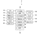
図1に示す車載の走行支援システム2は、カメラ10と、ミリ波レーダ12と、操舵角センサ14と、車速センサ16と、ウィンカースイッチ18と、支援スイッチ20と、走行支援装置30と、パワートレインシステム50と、ブレーキシステム52と、ステアリングシステム54と、報知システム56とを備えている。
Hereinafter, embodiments of the present disclosure will be described based on the drawings.
[1. Constitution]
The on-vehicle
カメラ10は、例えば車両の前方側と後方側とにそれぞれ取り付けられており、車両100の周囲を撮像した画像データを検出情報として走行支援装置30に出力する。
ミリ波レーダ12は、例えば車両の前方側と後方側とにそれぞれ取り付けられており、送信したミリ波が車両の周囲の他車両および歩行者等の物体に反射された反射波を受信するまでの時間に基づいて、物体までの距離を算出する。さらに、反射波の受信方向により車両に対する物体の方位、すなわち角度が定まる。ミリ波レーダ12は、計算した距離と角度とを検出情報として走行支援装置30に出力する。
The
The
尚、ミリ波レーダ12等の電波を照射するレーダに代えて、レーザ光を照射するLIDARを使用してもよい。
操舵角センサ14は車両の操舵角を検出する。車速センサ16は、車両100の車速を検出する。ウィンカースイッチ18は、車両の乗員であるドライバが操作することにより、車両が右左折をするとき、あるいは車線変更をするときに進行方向側のウィンカーを点滅させるスイッチである。
It should be noted that LIDAR for emitting laser light may be used instead of the radar for emitting radio waves such as the
The
ウィンカースイッチ18は、ウィンカーレバーのようにレバー式のスイッチでもよいし、押しボタン式のスイッチでもよい。また、ウィンカースイッチ18は、機械式のスイッチに限らず、ディスプレイ上に表示されるスイッチでもよい。また、スイッチに限らず、音声により車両の進行方向を入力し、進行方向側のウィンカーを点滅させてもよい。
The
支援スイッチ20は、オンであれば走行支援装置30が車線変更の制御を実行することを許可し、オフであれば走行支援装置30が車線変更の制御を実行することを禁止する。
走行支援装置30は、CPUと、RAM、ROM、フラッシュメモリ等の半導体メモリとを備えるマイクロコンピュータを搭載している。尚、走行支援装置30を構成するマイクロコンピュータの数は一つでも複数でもよい。
The
The
走行支援装置30の各機能は、CPUがROMまたはフラッシュメモリ等の非遷移的実体的記録媒体に記憶されているプログラムを実行することにより実現される。このプログラムが実行されることにより、プログラムに対応する方法が実行される。
Each function of the
走行支援装置30は、CPUがプログラムを実行することで実現される機能の構成として、認識部32と、センサ判定部34と、制御決定部36と、軌跡設定部38と、走行制御部40と、報知部42とを備えている。走行支援装置30を構成するこれらの要素を実現する手法は、ソフトウェアに限るものではなく、その一部または全部の要素を、論理回路やアナログ回路等を組み合わせたハードウェアを用いて実現してもよい。
The
認識部32は、車両の周囲の物体と、車両が走行する道路の車線とを検出するカメラ10とミリ波レーダ12とから取得する検出情報に基づいて、車両の周囲の物体と、車両が走行する道路の車線とを認識する。
The
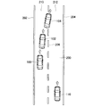
例えば、図2に示すように、認識部32は、カメラ10から取得する車両100の前方および後方の画像データに基づいて、車両100が走行する道路200の白線202、204、206の位置、白線同士の間隔が示す車線幅、白線の曲率等を算出する。
For example, as illustrated in FIG. 2, the
認識部32は、白線202、204、206を認識することにより、車両100が走行する道路200の車線210、212を認識する。尚、図2において、車両100、102、104は車線変更をしている同じ車両を表している。
The
さらに、認識部32は、白線202、204、206の位置と車両100の位置とに基づいて、車線210、212とのうち、車両が走行している走行車線210と、走行車線210に隣接している隣接車線212とを認識する。認識部32は、例えば、車両100の位置を図示しないGPS装置から取得する。
Furthermore, the
認識部32は、カメラ10とミリ波レーダ12とから取得する車両100の前方および後方の検出情報に基づいて、走行車線210に隣接する隣接車線212を走行する他車両110を認識する。図2では、他車両110は車両100の後方を走行している。
The
認識部32は、カメラ10から取得する車両の前方および後方の画像データに基づいて、他車両の位置と、他車両の位置の変化量から他車両の車速とを算出する。また、認識部32は、ミリ波レーダ12から取得する車両の前方と側方と後方との検出情報に基づいて、他車両の位置と、車両に対する他車両の相対速度等を算出する。
The
センサ判定部34は、走行支援装置30が車両の車線変更を制御する情報を取得する周囲検出センサとして、カメラ10とミリ波レーダ12とが異常であるか否かを判定する。
センサ判定部34は、カメラ10から取得する各フレームの画像データが変化しない場合、カメラ10が異常であると判定する。また、センサ判定部34は、カメラ10とミリ波レーダ12とからそれぞれ入力する信号のレベルが一定レベルで変化しないか、あるいは信号のレベルが正常範囲を超えている場合、異常であると判定する。
The
When the image data of each frame acquired from the
制御決定部36は、カメラ10とミリ波レーダ12とが正常であるか異常であるかに基づいて、走行支援装置30が車両の車線変更を制御するか否かを決定する。
軌跡設定部38は、認識部32による認識結果と車速センサ16の出力とに基づいて、車両が車線変更をするときに、他車両との衝突を回避するように走行軌跡を設定する。軌跡設定部38は、車線変更中に隣接車線を走行する他車両の車速が変化すると、新たに走行軌跡を設定してもよい。車線変更をするときの走行軌跡は、車線変更中に車両に加わる横加速度が車両の乗員に不快感を与えない値以下になるように設定される。
The
The
走行制御部40は、軌跡設定部38が設定する走行軌跡を車両が車線変更中に走行するように、パワートレインシステム50、ブレーキシステム52、ステアリングシステム54を制御する。つまり、走行制御部40は、車線変更中において、車両の車速と操舵角とを制御する。
The
報知部42は、周囲検出センサであるカメラ10とミリ波レーダ12との少なくとも一つが異常の場合、報知システム56に指示して車両の乗員に周囲検出センサの異常を報知する。
The
パワートレインシステム50は、走行制御部40から指令される駆動出力にしたがって、駆動源として内燃機関を搭載している場合にはスロットル装置の開度および燃料噴射量を制御し、駆動源としてモータを搭載している場合にはモータへの供給電力を制御する。
When the internal combustion engine is mounted as a drive source,
ブレーキシステム52は、走行制御部40から指令される制動力にしたがって、油圧式ブレーキの液圧回路に設けられたアクチュエータを制御する。車両が駆動源としてモータを搭載している場合には、ブレーキシステム52は、走行制御部40から指令される制動力にしたがって、モータへの供給電力を制御して回生ブレーキによる制動力を生成してもよい。
The
ステアリングシステム54は、走行制御部40から指令されるトルクにしたがってステアリングハンドルを駆動し、車両を操舵する。
報知システム56は、報知部42からの指示によりスピーカ、ディスプレイ、ランプ、バイブレータ等を作動させる。
The
The
[2.処理]
以下、走行支援装置30が実行する走行支援処理を、図3のフローチャートに基づいて説明する。図3のフローチャートは所定時間間隔で常時実行される。
[2. processing]
Hereinafter, the driving support processing executed by the driving
S400において制御決定部36は、支援スイッチ20の出力がオンであるか否かを判定する。S400の判定がNoであり、支援スイッチ20がオフの場合、車線変更の制御は禁止されているので、本処理は終了する。
In S400, the
S400の判定がYesであり、支援スイッチ20がオンの場合、車線変更の制御は許可されているので、S402において認識部32は、カメラ10とミリ波レーダ12とから取得する検出情報に基づいて、車両の周囲の物体と、車両が走行する道路の車線とを認識する。
When the determination in S400 is Yes and the
S404において制御決定部36は、走行制御部40に車線変更を制御させる事象が発生しているか否かを判定する。走行制御部40に車線変更を制御させる事象として、例えば、以下の(1)〜(3)等が考えられる。制御決定部36は、(2)または(3)の事象の発生で走行制御部40に車線変更を制御させる場合、車線変更する側のウィンカーを走行制御部40に点灯させる。
In S404, the
(1)車両の乗員から車線変更が指示されている。車両の乗員は、ウィンカースイッチ18等のスイッチを操作するか、あるいは音声入力等により車両の車線変更を指示する。
(2)設定した車速で車両を走行させるクルーズコントロール中に、車両が走行している走行車線の前方を、設定した車速よりも所定速度以上遅い他車両が走行している。
(1) A lane change is instructed by a vehicle occupant. The occupant of the vehicle operates a switch such as the
(2) During cruise control for causing the vehicle to travel at the set vehicle speed, another vehicle traveling at a predetermined speed or more slower than the set vehicle speed is traveling ahead of the traveling lane on which the vehicle is traveling.
(3)車両の前方に障害物が存在している。
S404の判定がNoであり、走行制御部40に車線変更を制御させる事象が発生していない場合、本処理は終了する。
(3) An obstacle exists in front of the vehicle.
If the determination in S404 is No, and there is no event that causes the
S404の判定がYesであり、走行制御部40に車線変更を制御させる事象が発生している場合、S406においてセンサ判定部34は、前述したように、カメラ10とミリ波レーダ12とから取得する検出情報の内容および検出情報の信号レベルに基づいて、カメラ10とミリ波レーダ12との少なくとも一つが異常であるか否かを判定する。
If the determination in S404 is Yes and there is an event that causes the traveling
S406の判定がNoであり、周囲検出センサであるカメラ10とミリ波レーダ12との両方が正常の場合、制御決定部36は、周囲検出センサを含む各種センサから取得する情報に基づいて走行制御部40に車線変更を制御させることを決定する。これにより、処理はS408に移行する。
If the determination in S406 is No and both the
S408において軌跡設定部38は、認識部32による認識結果と、車速センサ16から取得する車両100の車速とに基づいて、車両が車線変更をするときの走行軌跡を設定する。
In S408, the
そして、S408において走行制御部40は、軌跡設定部38が設定する走行軌跡から車両102、104の位置が外れずに車両が車線変更をするように、パワートレインシステム50とブレーキシステム52とステアリングシステム54とを制御する。
Then, in S408, the
S406の判定がYesであり、カメラ10とミリ波レーダ12との少なくとも一つが異常の場合、S410において報知部42は、報知システム56に指示し、音声、画像、光、振動等により周囲検出センサの異常を報知する。
If the determination in S406 is Yes and at least one of the
S412において制御決定部36は、図2に示す車両102、104のように、車線変更を開始しているか否かを判定する。S412の判定がNoであり、車両100のように車線変更を開始していない場合、制御決定部36は、カメラ10とミリ波レーダ12との少なくとも一つが異常のために走行制御部40が車線変更を制御するための適切な検出情報を取得できないと判断する。この場合、処理はS418に移行する。
In S412, the
S412の判定がYesであり、車両102、104のように車線変更を開始し隣接車線212に向けて進行方向を変えている場合、S414において制御決定部36は、隣接車線212に車両102、104の少なくとも一部が進入したか否かを判定する。
If the determination in S412 is YES and the lane change is started and the traveling direction is changed toward the
S414の判定がNoであり、隣接車線212に車両102がまだ進入していない場合、制御決定部36は、周囲検出センサが異常のために走行制御部40が車線変更の制御を継続するための検出情報を取得できないと判断し、S418に処理を移行する。
If the determination in S414 is No, and the
S414の判定がYesであり、隣接車線212に車両104の少なくとも一部が進入している場合、制御決定部36は、周囲検出センサが異常になる前に取得していた検出情報に基づいて走行制御部40に車線変更を制御させることを決定する。これにより、S416において走行制御部40は、周囲検出センサが異常になる前に取得していた検出情報に基づいて軌跡設定部38が設定した走行軌跡に沿って車線変更を制御する。
When the determination in S414 is Yes and at least a part of the
尚、周囲検出センサが異常になる前に取得していた検出情報とは、隣接車線212において車両104の後方を走行している他車両110と車両104との距離および相対速度、白線202、204、206の位置等である。
Note that the detection information obtained before the surrounding detection sensor became abnormal means the distance and relative speed between the
隣接車線212に車両104の少なくとも一部が進入している状態で、周囲検出センサであるカメラ10とミリ波レーダ12との少なくとも一つが異常になると、速やかに車線変更を終了することが望ましい。そこで、走行制御部40は、周囲検出センサが異常になる前よりも、車両104の車速を上昇させたり、操舵角を大きくしたりすることにより、車線変更を極力早く終了させる。
When at least a part of the
S418において制御決定部36は、走行制御部40に車線変更の制御を中止させる。これにより、走行制御部40は車線変更の制御を中止する。
[3.効果]
以上説明した上記実施形態では、以下の効果を得ることができる。
In S418, the
[3. effect]
The following effects can be obtained in the embodiment described above.
(1)走行制御部40が車線変更を制御するための検出情報を出力する周囲検出センサが正常であるか異常であるかを判定するセンサ判定部34の判定結果に基づいて、走行制御部40が車両の車線変更を制御するか否かを決定する。したがって、車両が適切に車線変更するための検出情報を出力する周囲検出センサが正常であるか異常であるかを考慮して車両の車線変更を適切に制御できる。
(1) The traveling
(2)周囲検出センサの少なくとも一つが異常であることを検出したタイミングによって、車線変更の制御を中止するか継続するかを適切に決定できる。例えば、車線変更の制御を開始していても、車両がまだ車線変更を開始していないか、車線変更を開始しているが車両が隣接車線に進入せずまだ走行車線を走行中の場合には、周囲検出センサの少なくとも一つが異常であれば走行の安全を考慮して車線変更を中止する。 (2) Depending on the timing at which at least one of the surrounding detection sensors detects an abnormality, it is possible to appropriately determine whether to stop or continue the control of the lane change. For example, when the lane change control has been started, the vehicle has not yet started lane change, or the lane change has been started but the vehicle has not yet entered the adjacent lane and is still traveling in the traveling lane. If the at least one of the surrounding detection sensors is abnormal, the lane change is canceled in consideration of the traveling safety.
一方、車線変更の制御により車両の少なくとも一部が隣接車線に進入しているときに周囲検出センサの少なくとも一つの異常を検出すると、周囲検出センサが異常になる前に周囲検出センサから取得していた検出情報に基づいて、車線変更の制御を継続する。周囲検出センサが異常になる前に周囲検出センサから取得していた検出情報に基づいて、車線変更を完了できるとの判断はすでになされている。 On the other hand, when at least one abnormality of the surroundings detection sensor is detected while at least a part of the vehicle is entering the adjacent lane by control of lane change, the surroundings detection sensor is acquired from the surroundings detection sensor before becoming abnormal. Control of lane change is continued based on the detected information. It is already determined that the lane change can be completed based on detection information obtained from the surroundings detection sensor before the surroundings detection sensor becomes abnormal.
(3)周囲検出センサの少なくとも一つが異常であるときに車線変更の制御を継続する場合、車速を上昇したり、車線変更側の隣接車線への操舵角を大きくしたりすることにより、より早く安全に車線変更を完了することができる。 (3) When control of lane change is continued when at least one of the surroundings detection sensors is abnormal, the vehicle speed can be increased by increasing the vehicle speed or increasing the steering angle to the adjacent lane on the lane change side. You can safely complete the lane change.
(4)車線変更の制御が開始されてから周囲検出センサの少なくとも一つの異常を検出すると、音声、画像、光、振動等によりセンサの異常を報知する。これにより、例えば、ドライバがウィンカーレバーを操作して車線変更を指示したにも関わらず車線変更が実行されない場合、ドライバは車線変更が実行されない理由を理解できる。 (4) When at least one abnormality of the surrounding area detection sensor is detected after control of lane change is started, the abnormality of the sensor is notified by voice, image, light, vibration or the like. This allows the driver to understand the reason why the lane change is not performed, for example, if the lane change is not performed although the driver operates the blinker lever to instruct the lane change.
以上説明した上記実施形態において、カメラ10とミリ波レーダ12とが周囲検出センサに対応し、他車両110が車両の周囲の物体に対応し、ウィンカースイッチ18が入力装置に対応する。
In the embodiment described above, the
また、上記実施形態において、S400、S404、S412、S414、S418が制御決定部36としての処理に対応し、S402が認識部32としての処理に対応し、S406がセンサ判定部34としての処理に対応し、S410が報知部42としての処理に対応し、S408、S416が走行制御部40としての処理に対応する。
In the above embodiment, S400, S404, S412, S414, and S418 correspond to the processing as the
[4.他の実施形態]
(1)上記実施形態では、周囲検出センサとしてカメラ10とミリ波レーダ12との少なくとも一つが異常になった場合、走行車線210から隣接車線212に車両が進入していないと、走行支援装置30は車線変更の制御を中止した。
[4. Other embodiments]
(1) In the above embodiment, when at least one of the
これに対し、周囲検出センサの少なくとも一つが異常でも正常な周囲検出センサが存在すれば、車両が隣接車線212に進入していなくても、正常な周囲検出センサから取得する検出情報に基づいて、走行支援装置30は車線変更を制御してもよい。
On the other hand, if there is a normal surrounding detection sensor even if at least one of the surrounding detection sensors is abnormal, even if the vehicle does not enter the
(2)車両の車速が遅く所定速度未満の場合、あるいは隣接車線において車両に対し車両の後方を走行している他車両の相対速度が遅く所定速度未満の場合、周囲検出センサの少なくとも一つが正常であれば、車両が隣接車線に進入していない場合にも車両の車線変更を制御してもよい。 (2) At least one of the surroundings detection sensors is normal if the vehicle speed of the vehicle is low and less than the predetermined speed, or if the relative speed of the other vehicle traveling behind the vehicle relative to the vehicle in the adjacent lane is low In this case, the lane change of the vehicle may be controlled even when the vehicle is not in the adjacent lane.
(3)周囲検出センサの少なくとも一つが異常でも正常な周囲検出センサが存在すれば、異常になる前の周囲検出センサの検出範囲で取得していた検出情報を適用できなくなるまで、走行支援装置30は車線変更を制御してもよい。例えば、異常になる前の周囲検出センサの検出範囲が、車両の前方100mまでであれば、車両が進行方向前方に向かって100m走行するまで、走行支援装置30は車線変更を制御してもよい。
(3) If there is a normal surrounding detection sensor even if at least one of the surrounding detection sensors is abnormal, the driving
そして、異常になる前のセンサの検出範囲を越えて車両が走行し、異常になる前の周囲検出センサから取得していた情報を適用できなくなると、走行支援装置30は、車線変更の制御を中止する。この場合、車線変更の制御を中止することを、報知部42が報知することが望ましい。
When the vehicle travels beyond the detection range of the sensor before becoming abnormal and the information acquired from the surroundings detection sensor before becoming abnormal can not be applied, the driving
(4)車線変更を制御中に周囲検出センサの少なくとも一つが異常になっても、異常になる前に取得していた検出情報に基づいて車線変更を完了できる場合、図2の車両100、102、104の位置に関わらず、走行支援装置30は車線変更を継続してもよい。異常になる前に周囲検出センサから取得していた検出情報では車線変更を安全に完了できない場合には、走行支援装置30は車線変更を中止することが望ましい。
(4) Even if at least one of the surroundings detection sensors becomes abnormal while controlling the lane change, if the lane change can be completed based on the detection information acquired before the abnormality, the
(5)上記実施形態では、カメラ10とミリ波レーダ12とを周囲検出センサして使用した。これに対し、周囲検出センサは、例えばカメラ10またはミリ波レーダ12の一方だけでもよい。また、周囲検出センサとして、カメラ10とミリ波レーダ12とに他のセンサを加えてもよいし、カメラ10とミリ波レーダ12と以外の他のセンサを使用してもよい。
(5) In the said embodiment, the
(6)上記実施形態における一つの構成要素が有する複数の機能を複数の構成要素によって実現したり、一つの構成要素が有する一つの機能を複数の構成要素によって実現したりしてもよい。また、複数の構成要素が有する複数の機能を一つの構成要素によって実現したり、複数の構成要素によって実現される一つの機能を一つの構成要素によって実現したりしてもよい。また、上記実施形態の構成の一部を省略してもよい。また、上記実施形態の構成の少なくとも一部を、他の上記実施形態の構成に対して付加又は置換してもよい。尚、特許請求の範囲に記載した文言のみによって特定される技術思想に含まれるあらゆる態様が本発明の実施形態である。 (6) The plurality of functions of one component in the above embodiment may be realized by a plurality of components, or one function of one component may be realized by a plurality of components. Further, a plurality of functions possessed by a plurality of components may be realized by one component, or a single function realized by a plurality of components may be realized by a single component. In addition, part of the configuration of the above embodiment may be omitted. In addition, at least a part of the configuration of the above-described embodiment may be added to or replaced with the configuration of the other above-described embodiment. It is to be noted that all aspects included in the technical concept specified by only the words described in the claims are the embodiments of the present invention.
(7)上述した走行支援装置30の他、当該走行支援装置30を構成要素とする走行支援システム2、当該走行支援装置30としてコンピュータを機能させるための走行支援プログラム、この走行支援プログラムを記録した記録媒体、走行支援方法など、種々の形態で本発明を実現することもできる。
(7) A driving
2:走行支援システム、10:カメラ(周囲検出センサ)、12:ミリ波レーダ(周囲検出センサ)、14操舵角センサ、16:車速センサ、18:ウィンカースイッチ(入力装置)、30:走行支援装置、32:認識部、34:センサ判定部、36:制御決定部、38:軌跡設定部、40:走行制御部、42:報知部、100、102、104:車両、110:他車両(物体)、200:道路、202、204、206:白線、210、走行車線、212:隣接車線 2: driving support system, 10: camera (surrounding detection sensor), 12: millimeter wave radar (surrounding detection sensor), 14 steering angle sensor, 16: vehicle speed sensor, 18: blinker switch (input device), 30: driving support device , 32: recognition unit, 34: sensor determination unit, 36: control determination unit, 38: trajectory setting unit, 40: travel control unit, 42: notification unit, 100, 102, 104: vehicle, 110: other vehicle (object) , 200: road, 202, 204, 206: white line, 210, driving lane, 212: adjacent lane
Claims (5)
少なくとも前記認識部による認識結果に基づいて前記車両の車線変更を制御する走行制御部(40、S408、S416)と、
前記周囲検出センサが正常であるか異常であるかを判定するセンサ判定部(34、S406)と、
前記センサ判定部の判定結果に基づいて、前記走行制御部が車線変更を制御するか否かを決定し、前記周囲検出センサが全て正常であると前記センサ判定部が判定する場合、前記走行制御部が車線変更を制御することを決定し、前記周囲検出センサの少なくとも一つが異常であると前記センサ判定部が判定する場合、前記車両が走行している走行車線から車線変更をする側の隣接車線に進入していない場合は前記走行制御部による車線変更の制御を中止し、前記車両の少なくとも一部が前記隣接車線に進入している場合、前記周囲検出センサが異常になる前よりも車速を上昇させること、ならびに操舵角を大きくすることの少なくともいずれかを実行して前記走行制御部による車線変更の制御を継続する制御決定部(36、S400、S404、S412、S414、S418)と、
を備える走行支援装置。 Acquired from one or more surrounding detection sensors (10, 12) that detect an object (110) around a vehicle (100, 102, 104) and a lane (210, 212) of a road (200) on which the vehicle travels A recognition unit (32, S402) for recognizing the object and the lane based on the detected information;
A travel control unit (40, S408, S416) for controlling a lane change of the vehicle based on at least a recognition result by the recognition unit;
A sensor determination unit (34, S406) that determines whether the surrounding detection sensor is normal or abnormal;
Based on the determination result of the sensor determination unit, the travel control unit determines whether or not to control a lane change, and when the sensor determination unit determines that the surrounding detection sensors are all normal, the travel control Unit determines to control the lane change, and when the sensor determination unit determines that at least one of the surroundings detection sensors is abnormal, the adjacent on the lane where the vehicle is traveling is to be changed When the vehicle has not entered the lane, the travel control unit stops controlling the lane change, and when at least a part of the vehicle enters the adjacent lane, the vehicle speed is higher than before the surrounding area detection sensor becomes abnormal. raising, as well as control decision unit to continue the control of the lane change by the travel control unit to perform at least one of increasing the steering angle (36, S400, S40 , S412, S414, S418 and),
Driving support device comprising
前記認識部は、前記周囲検出センサの少なくとも一つから、前記車両が走行している走行車線に隣接する隣接車線において前記車両の後方を走行する他車両の前記検出情報を取得する、
走行支援装置。 In the driving support device according to claim 1,
The recognition unit acquires the detection information of another vehicle traveling behind the vehicle in an adjacent lane adjacent to a traveling lane in which the vehicle is traveling, from at least one of the surrounding area detection sensors.
Driving support device.
前記制御決定部(S404)は、前記車両の乗員により車線変更の指示が入力装置(18)から入力されると、前記センサ判定部の判定結果に基づいて、前記走行制御部が車線変更を制御するか否かを決定する、
走行支援装置。 In the driving support device according to claim 1 or 2,
The control determination unit (S404) controls the lane change based on the determination result of the sensor determination unit when the driver of the vehicle receives an instruction to change the lane from the input device (18). Decide whether to
Driving support device.
前記制御決定部は、前記走行制御部が車線変更を制御中に、前記周囲検出センサの少なくとも一つが異常であると前記センサ判定部が判定すると、前記周囲検出センサが異常であると判定される前に前記走行制御部が前記周囲検出センサから取得していた検出情報に基づいて、前記走行制御部による車線変更の制御を継続するか中止するかを決定する、
走行支援装置。 The driving support apparatus according to any one of claims 1 to 3
The control determination unit determines that the surrounding area detection sensor is abnormal when the sensor determination unit determines that at least one of the surrounding area detection sensors is abnormal while the travel control unit controls a lane change. Based on the detection information previously acquired by the traveling control unit from the surrounding area detection sensor, it is determined whether to continue or cancel the control of the lane change by the traveling control unit.
Driving support device.
前記走行制御部は、車線変更を制御するときに、少なくとも前記車両の操舵角を制御す
る、
走行支援装置。 In the driving support device according to any one of claims 1 to 4 .
The travel control unit controls at least a steering angle of the vehicle when controlling a lane change.
Driving support device.
Priority Applications (5)
| Application Number | Priority Date | Filing Date | Title |
|---|---|---|---|
| JP2016053919A JP6524943B2 (en) | 2016-03-17 | 2016-03-17 | Driving support device |
| CN201780017111.5A CN108778886B (en) | 2016-03-17 | 2017-03-16 | driving aids |
| PCT/JP2017/010692 WO2017159792A1 (en) | 2016-03-17 | 2017-03-16 | Travel assistance device |
| US16/084,779 US10689005B2 (en) | 2016-03-17 | 2017-03-16 | Traveling assist device |
| DE112017001351.8T DE112017001351B4 (en) | 2016-03-17 | 2017-03-16 | DRIVING ASSISTANCE DEVICE |
Applications Claiming Priority (1)
| Application Number | Priority Date | Filing Date | Title |
|---|---|---|---|
| JP2016053919A JP6524943B2 (en) | 2016-03-17 | 2016-03-17 | Driving support device |
Publications (3)
| Publication Number | Publication Date |
|---|---|
| JP2017165322A JP2017165322A (en) | 2017-09-21 |
| JP2017165322A5 JP2017165322A5 (en) | 2018-05-31 |
| JP6524943B2 true JP6524943B2 (en) | 2019-06-05 |
Family
ID=59851723
Family Applications (1)
| Application Number | Title | Priority Date | Filing Date |
|---|---|---|---|
| JP2016053919A Active JP6524943B2 (en) | 2016-03-17 | 2016-03-17 | Driving support device |
Country Status (5)
| Country | Link |
|---|---|
| US (1) | US10689005B2 (en) |
| JP (1) | JP6524943B2 (en) |
| CN (1) | CN108778886B (en) |
| DE (1) | DE112017001351B4 (en) |
| WO (1) | WO2017159792A1 (en) |
Families Citing this family (19)
| Publication number | Priority date | Publication date | Assignee | Title |
|---|---|---|---|---|
| JP6387369B2 (en) * | 2016-05-23 | 2018-09-05 | 本田技研工業株式会社 | Travel control device |
| JP6643297B2 (en) * | 2017-11-16 | 2020-02-12 | 株式会社Subaru | Driving support device |
| CN111565992A (en) * | 2018-01-18 | 2020-08-21 | 本田技研工业株式会社 | vehicle control device |
| KR102485352B1 (en) * | 2018-04-11 | 2023-01-05 | 현대자동차주식회사 | Vehicle apparatus, system having the same and method for changing automatically operable range thereof |
| US20190315405A1 (en) * | 2018-04-11 | 2019-10-17 | Hyundai Motor Company | Apparatus and method for controlling lane change in vehicle |
| EP3569460B1 (en) | 2018-04-11 | 2024-03-20 | Hyundai Motor Company | Apparatus and method for controlling driving in vehicle |
| US11597403B2 (en) | 2018-04-11 | 2023-03-07 | Hyundai Motor Company | Apparatus for displaying driving state of vehicle, system including the same and method thereof |
| US11548509B2 (en) | 2018-04-11 | 2023-01-10 | Hyundai Motor Company | Apparatus and method for controlling lane change in vehicle |
| US10843710B2 (en) | 2018-04-11 | 2020-11-24 | Hyundai Motor Company | Apparatus and method for providing notification of control authority transition in vehicle |
| EP3552913B1 (en) | 2018-04-11 | 2021-08-18 | Hyundai Motor Company | Apparatus and method for controlling to enable autonomous system in vehicle |
| EP3552902B1 (en) | 2018-04-11 | 2025-05-28 | Hyundai Motor Company | Apparatus and method for providing a driving path to a vehicle |
| US11351989B2 (en) | 2018-04-11 | 2022-06-07 | Hyundai Motor Company | Vehicle driving controller, system including the same, and method thereof |
| CN109664880B (en) * | 2019-02-15 | 2020-08-04 | 东软睿驰汽车技术(沈阳)有限公司 | Method and device for checking whether vehicle is subjected to broken detection |
| JP2021133891A (en) * | 2020-02-28 | 2021-09-13 | いすゞ自動車株式会社 | Drive support device and drive support method |
| JP7466396B2 (en) * | 2020-07-28 | 2024-04-12 | 株式会社Soken | Vehicle control device |
| US20240010242A1 (en) * | 2020-11-11 | 2024-01-11 | Sony Semiconductor Solutions Corporation | Signal processing device and signal processing method |
| MX2024005895A (en) * | 2021-11-22 | 2024-05-31 | Nissan Motor | Travel assistance method and travel assistance device for vehicle. |
| DE102021213571A1 (en) | 2021-11-30 | 2023-06-01 | Volkswagen Aktiengesellschaft | Method and assistance system for supporting a lane change maneuver and motor vehicle |
| KR20250062801A (en) * | 2023-10-31 | 2025-05-08 | 현대자동차주식회사 | Apparatus for controlling autonomous driving and method thereof |
Family Cites Families (42)
| Publication number | Priority date | Publication date | Assignee | Title |
|---|---|---|---|---|
| JP3743778B2 (en) | 1995-06-16 | 2006-02-08 | 株式会社壹会 | System ceiling |
| US6069581A (en) * | 1998-02-20 | 2000-05-30 | Amerigon | High performance vehicle radar system |
| US6400308B1 (en) * | 1998-02-20 | 2002-06-04 | Amerigon Inc. | High performance vehicle radar system |
| JP5055933B2 (en) * | 2006-10-05 | 2012-10-24 | トヨタ自動車株式会社 | Driving support device |
| US7885730B2 (en) * | 2007-01-26 | 2011-02-08 | Nexteer (Beijing) Technology Co., Ltd. | Systems, methods and computer program products for lane change detection and handling of lane keeping torque |
| JP2009274594A (en) * | 2008-05-15 | 2009-11-26 | Hitachi Ltd | Lane change support device |
| EP2380348A4 (en) * | 2008-12-19 | 2012-06-13 | Delphi Tech Inc | Electronic side view display system |
| US20110190972A1 (en) * | 2010-02-02 | 2011-08-04 | Gm Global Technology Operations, Inc. | Grid unlock |
| CN201961311U (en) * | 2011-02-18 | 2011-09-07 | 深圳精美精科技有限公司 | Auxiliary system for safe driving of automobile |
| US9542846B2 (en) * | 2011-02-28 | 2017-01-10 | GM Global Technology Operations LLC | Redundant lane sensing systems for fault-tolerant vehicular lateral controller |
| JP5892876B2 (en) * | 2011-07-28 | 2016-03-23 | クラリオン株式会社 | In-vehicle environment recognition system |
| US9772196B2 (en) * | 2013-08-23 | 2017-09-26 | Cellepathy Inc. | Dynamic navigation instructions |
| KR101439017B1 (en) * | 2013-04-11 | 2014-10-30 | 현대자동차주식회사 | System for controlling change of lane |
| DE102013213171A1 (en) * | 2013-07-04 | 2015-01-08 | Robert Bosch Gmbh | Method and device for operating a motor vehicle in an automated driving operation |
| US9454816B2 (en) * | 2013-10-23 | 2016-09-27 | International Electronic Machines Corp. | Enhanced stereo imaging-based metrology |
| KR102200121B1 (en) * | 2014-02-17 | 2021-01-08 | 삼성전자 주식회사 | Apparatus and method forecasting vehicle flow |
| DE102015102163B4 (en) * | 2014-02-18 | 2021-01-28 | Subaru Corporation | Battery voltage control and method for controlling a battery voltage |
| JP6307383B2 (en) * | 2014-08-07 | 2018-04-04 | 日立オートモティブシステムズ株式会社 | Action planning device |
| JP2016053919A (en) | 2014-09-04 | 2016-04-14 | 東芝テック株式会社 | Server device and program |
| JP5970513B2 (en) * | 2014-09-29 | 2016-08-17 | 富士重工業株式会社 | Driving support control device |
| RU2682690C2 (en) * | 2014-10-22 | 2019-03-20 | Ниссан Мотор Ко., Лтд. | Driving assistance device |
| JP6035306B2 (en) * | 2014-10-27 | 2016-11-30 | 富士重工業株式会社 | Vehicle travel control device |
| CN104290745B (en) * | 2014-10-28 | 2017-02-01 | 奇瑞汽车股份有限公司 | Driving method of semi-automatic driving system for vehicle |
| JP2017013519A (en) * | 2015-06-26 | 2017-01-19 | 株式会社デンソー | Lane maintenance support device |
| US10940868B2 (en) * | 2015-07-10 | 2021-03-09 | Honda Motor Co., Ltd. | Vehicle control device, vehicle control method, and vehicle control program |
| KR101795250B1 (en) * | 2016-05-03 | 2017-11-07 | 현대자동차주식회사 | Path planning apparatus and method for autonomous vehicle |
| NL2016744B1 (en) * | 2016-05-09 | 2017-11-16 | Fugro Tech Bv | Fiber-optic based traffic and infrastructure monitoring system |
| KR102455835B1 (en) * | 2016-07-20 | 2022-10-18 | 현대모비스 주식회사 | Apparatus and method for determining deviation of wheel alignment of vehicle |
| US20180067496A1 (en) * | 2016-09-06 | 2018-03-08 | Delphi Technologies, Inc. | Automated vehicle lane change control system |
| IL288191B2 (en) * | 2016-12-23 | 2023-10-01 | Mobileye Vision Technologies Ltd | A navigation system with forced commitment constraints |
| JP6801591B2 (en) * | 2017-06-06 | 2020-12-16 | トヨタ自動車株式会社 | Steering support device |
| JP6642522B2 (en) * | 2017-06-06 | 2020-02-05 | トヨタ自動車株式会社 | Lane change support device |
| JP6791021B2 (en) * | 2017-06-06 | 2020-11-25 | トヨタ自動車株式会社 | Steering support device |
| JP6627822B2 (en) * | 2017-06-06 | 2020-01-08 | トヨタ自動車株式会社 | Lane change support device |
| JP6760204B2 (en) * | 2017-06-06 | 2020-09-23 | トヨタ自動車株式会社 | Steering support device |
| JP6589941B2 (en) * | 2017-06-06 | 2019-10-16 | トヨタ自動車株式会社 | Steering support device |
| JP6627821B2 (en) * | 2017-06-06 | 2020-01-08 | トヨタ自動車株式会社 | Lane change support device |
| DE102017006051A1 (en) * | 2017-06-27 | 2018-12-27 | Lucas Automotive Gmbh | System and method for a direction indicator of a motor vehicle |
| EP3707572B1 (en) * | 2017-11-10 | 2023-08-23 | Nvidia Corporation | Systems and methods for safe and reliable autonomous vehicles |
| JP6946972B2 (en) * | 2017-11-24 | 2021-10-13 | トヨタ自動車株式会社 | Vehicle control device |
| KR102127741B1 (en) * | 2018-03-20 | 2020-07-01 | 모빌아이 비젼 테크놀로지스 엘티디. | Systems and methods for navigation of vehicles |
| US20190051188A1 (en) * | 2018-09-27 | 2019-02-14 | Intel Corporation | Technologies for on-demand ad hoc cooperation for autonomous vehicles in emergency situations |
-
2016
- 2016-03-17 JP JP2016053919A patent/JP6524943B2/en active Active
-
2017
- 2017-03-16 WO PCT/JP2017/010692 patent/WO2017159792A1/en not_active Ceased
- 2017-03-16 CN CN201780017111.5A patent/CN108778886B/en active Active
- 2017-03-16 US US16/084,779 patent/US10689005B2/en active Active
- 2017-03-16 DE DE112017001351.8T patent/DE112017001351B4/en active Active
Also Published As
| Publication number | Publication date |
|---|---|
| DE112017001351T5 (en) | 2018-11-22 |
| CN108778886B (en) | 2021-04-27 |
| US10689005B2 (en) | 2020-06-23 |
| DE112017001351B4 (en) | 2023-05-25 |
| US20190077411A1 (en) | 2019-03-14 |
| JP2017165322A (en) | 2017-09-21 |
| WO2017159792A1 (en) | 2017-09-21 |
| CN108778886A (en) | 2018-11-09 |
Similar Documents
| Publication | Publication Date | Title |
|---|---|---|
| JP6524943B2 (en) | Driving support device | |
| JP6493272B2 (en) | Driving support device | |
| JP6638178B2 (en) | Vehicle control system, vehicle control method, and program | |
| JP6593607B2 (en) | Vehicle control device | |
| JP6668895B2 (en) | Driving support device | |
| JP6596772B2 (en) | Vehicle control device, vehicle control method, and program | |
| JP6327244B2 (en) | Vehicle control device | |
| JP6763327B2 (en) | Collision avoidance device | |
| JP2019043313A (en) | Vehicle control device | |
| JP2011512283A (en) | Vehicle driver support system and method for maintaining lanes separated by lane marks | |
| CN111661042B (en) | vehicle control device | |
| JP2017100681A (en) | Travel control apparatus | |
| JP2004331023A (en) | Driving operation assist device for vehicle and vehicle equipped with the device | |
| WO2019077669A1 (en) | Vehicle control device | |
| JP7213149B2 (en) | VEHICLE CONTROL DEVICE, VEHICLE, OPERATING METHOD AND PROGRAM OF VEHICLE CONTROL DEVICE | |
| US20230234608A1 (en) | Path generation apparatus and path generation method | |
| JP7222343B2 (en) | Driving support device | |
| JP7489415B2 (en) | Driving assistance device, driving assistance method, and program | |
| JP7268464B2 (en) | vehicle controller | |
| JP7781136B2 (en) | Vehicle control program, vehicle control device, and vehicle control method | |
| JP7550834B2 (en) | Vehicle control device, vehicle control method, and program | |
| JP2018177148A (en) | Driving support device for vehicle | |
| JP7759827B2 (en) | Driving assistance device, driving assistance method, and program | |
| JP7288923B2 (en) | Driving support device, driving support method, and program | |
| JP6500932B2 (en) | Driving support device for vehicle |
Legal Events
| Date | Code | Title | Description |
|---|---|---|---|
| A521 | Request for written amendment filed |
Free format text: JAPANESE INTERMEDIATE CODE: A523 Effective date: 20180411 |
|
| A621 | Written request for application examination |
Free format text: JAPANESE INTERMEDIATE CODE: A621 Effective date: 20180416 |
|
| TRDD | Decision of grant or rejection written | ||
| A01 | Written decision to grant a patent or to grant a registration (utility model) |
Free format text: JAPANESE INTERMEDIATE CODE: A01 Effective date: 20190409 |
|
| A61 | First payment of annual fees (during grant procedure) |
Free format text: JAPANESE INTERMEDIATE CODE: A61 Effective date: 20190422 |
|
| R151 | Written notification of patent or utility model registration |
Ref document number: 6524943 Country of ref document: JP Free format text: JAPANESE INTERMEDIATE CODE: R151 |
|
| R250 | Receipt of annual fees |
Free format text: JAPANESE INTERMEDIATE CODE: R250 |
|
| R250 | Receipt of annual fees |
Free format text: JAPANESE INTERMEDIATE CODE: R250 |
|
| R250 | Receipt of annual fees |
Free format text: JAPANESE INTERMEDIATE CODE: R250 |
|
| R250 | Receipt of annual fees |
Free format text: JAPANESE INTERMEDIATE CODE: R250 |