WO2016208195A1 - Affichage tête haute et corps mobile équipé d'un affichage tête haute - Google Patents
Affichage tête haute et corps mobile équipé d'un affichage tête haute Download PDFInfo
- Publication number
- WO2016208195A1 WO2016208195A1 PCT/JP2016/003029 JP2016003029W WO2016208195A1 WO 2016208195 A1 WO2016208195 A1 WO 2016208195A1 JP 2016003029 W JP2016003029 W JP 2016003029W WO 2016208195 A1 WO2016208195 A1 WO 2016208195A1
- Authority
- WO
- WIPO (PCT)
- Prior art keywords
- optical system
- mirror
- display
- head
- image
- Prior art date
Links
Images


Classifications
-
- G—PHYSICS
- G02—OPTICS
- G02B—OPTICAL ELEMENTS, SYSTEMS OR APPARATUS
- G02B27/00—Optical systems or apparatus not provided for by any of the groups G02B1/00 - G02B26/00, G02B30/00
- G02B27/01—Head-up displays
- G02B27/0101—Head-up displays characterised by optical features
-
- B—PERFORMING OPERATIONS; TRANSPORTING
- B60—VEHICLES IN GENERAL
- B60K—ARRANGEMENT OR MOUNTING OF PROPULSION UNITS OR OF TRANSMISSIONS IN VEHICLES; ARRANGEMENT OR MOUNTING OF PLURAL DIVERSE PRIME-MOVERS IN VEHICLES; AUXILIARY DRIVES FOR VEHICLES; INSTRUMENTATION OR DASHBOARDS FOR VEHICLES; ARRANGEMENTS IN CONNECTION WITH COOLING, AIR INTAKE, GAS EXHAUST OR FUEL SUPPLY OF PROPULSION UNITS IN VEHICLES
- B60K35/00—Arrangement of adaptations of instruments
-
- B—PERFORMING OPERATIONS; TRANSPORTING
- B60—VEHICLES IN GENERAL
- B60R—VEHICLES, VEHICLE FITTINGS, OR VEHICLE PARTS, NOT OTHERWISE PROVIDED FOR
- B60R11/00—Arrangements for holding or mounting articles, not otherwise provided for
- B60R11/02—Arrangements for holding or mounting articles, not otherwise provided for for radio sets, television sets, telephones, or the like; Arrangement of controls thereof
-
- G—PHYSICS
- G02—OPTICS
- G02B—OPTICAL ELEMENTS, SYSTEMS OR APPARATUS
- G02B27/00—Optical systems or apparatus not provided for by any of the groups G02B1/00 - G02B26/00, G02B30/00
- G02B27/01—Head-up displays
-
- G—PHYSICS
- G02—OPTICS
- G02B—OPTICAL ELEMENTS, SYSTEMS OR APPARATUS
- G02B27/00—Optical systems or apparatus not provided for by any of the groups G02B1/00 - G02B26/00, G02B30/00
- G02B27/01—Head-up displays
- G02B27/017—Head mounted
- G02B27/0176—Head mounted characterised by mechanical features
-
- G—PHYSICS
- G02—OPTICS
- G02B—OPTICAL ELEMENTS, SYSTEMS OR APPARATUS
- G02B17/00—Systems with reflecting surfaces, with or without refracting elements
- G02B17/02—Catoptric systems, e.g. image erecting and reversing system
- G02B17/06—Catoptric systems, e.g. image erecting and reversing system using mirrors only, i.e. having only one curved mirror
- G02B17/0647—Catoptric systems, e.g. image erecting and reversing system using mirrors only, i.e. having only one curved mirror using more than three curved mirrors
- G02B17/0663—Catoptric systems, e.g. image erecting and reversing system using mirrors only, i.e. having only one curved mirror using more than three curved mirrors off-axis or unobscured systems in which not all of the mirrors share a common axis of rotational symmetry, e.g. at least one of the mirrors is warped, tilted or decentered with respect to the other elements
-
- G—PHYSICS
- G02—OPTICS
- G02B—OPTICAL ELEMENTS, SYSTEMS OR APPARATUS
- G02B17/00—Systems with reflecting surfaces, with or without refracting elements
- G02B17/08—Catadioptric systems
- G02B17/0804—Catadioptric systems using two curved mirrors
- G02B17/0816—Catadioptric systems using two curved mirrors off-axis or unobscured systems in which not all of the mirrors share a common axis of rotational symmetry, e.g. at least one of the mirrors is warped, tilted or decentered with respect to the other elements
-
- G—PHYSICS
- G02—OPTICS
- G02B—OPTICAL ELEMENTS, SYSTEMS OR APPARATUS
- G02B27/00—Optical systems or apparatus not provided for by any of the groups G02B1/00 - G02B26/00, G02B30/00
- G02B27/01—Head-up displays
- G02B27/0101—Head-up displays characterised by optical features
- G02B2027/011—Head-up displays characterised by optical features comprising device for correcting geometrical aberrations, distortion
-
- G—PHYSICS
- G02—OPTICS
- G02B—OPTICAL ELEMENTS, SYSTEMS OR APPARATUS
- G02B27/00—Optical systems or apparatus not provided for by any of the groups G02B1/00 - G02B26/00, G02B30/00
- G02B27/01—Head-up displays
- G02B27/0101—Head-up displays characterised by optical features
- G02B2027/013—Head-up displays characterised by optical features comprising a combiner of particular shape, e.g. curvature
-
- G—PHYSICS
- G02—OPTICS
- G02B—OPTICAL ELEMENTS, SYSTEMS OR APPARATUS
- G02B27/00—Optical systems or apparatus not provided for by any of the groups G02B1/00 - G02B26/00, G02B30/00
- G02B27/01—Head-up displays
- G02B27/0101—Head-up displays characterised by optical features
- G02B2027/014—Head-up displays characterised by optical features comprising information/image processing systems
-
- G—PHYSICS
- G02—OPTICS
- G02B—OPTICAL ELEMENTS, SYSTEMS OR APPARATUS
- G02B27/00—Optical systems or apparatus not provided for by any of the groups G02B1/00 - G02B26/00, G02B30/00
- G02B27/01—Head-up displays
- G02B27/0101—Head-up displays characterised by optical features
- G02B2027/0145—Head-up displays characterised by optical features creating an intermediate image
-
- G—PHYSICS
- G02—OPTICS
- G02B—OPTICAL ELEMENTS, SYSTEMS OR APPARATUS
- G02B27/00—Optical systems or apparatus not provided for by any of the groups G02B1/00 - G02B26/00, G02B30/00
- G02B27/01—Head-up displays
- G02B27/0149—Head-up displays characterised by mechanical features
- G02B2027/0154—Head-up displays characterised by mechanical features with movable elements
-
- G—PHYSICS
- G02—OPTICS
- G02B—OPTICAL ELEMENTS, SYSTEMS OR APPARATUS
- G02B27/00—Optical systems or apparatus not provided for by any of the groups G02B1/00 - G02B26/00, G02B30/00
- G02B27/01—Head-up displays
- G02B27/0179—Display position adjusting means not related to the information to be displayed
- G02B2027/0185—Displaying image at variable distance
-
- G—PHYSICS
- G02—OPTICS
- G02B—OPTICAL ELEMENTS, SYSTEMS OR APPARATUS
- G02B27/00—Optical systems or apparatus not provided for by any of the groups G02B1/00 - G02B26/00, G02B30/00
- G02B27/01—Head-up displays
- G02B27/0179—Display position adjusting means not related to the information to be displayed
Definitions
- This disclosure relates to a head-up display that projects an image on a transmissive reflective member to allow an observer to visually recognize a virtual image.
- Patent Document 1 discloses a display device that enables stereoscopic display.
- the display device includes a display panel, an imaging optical system, and an imaging position variable unit.
- the display panel is an image forming unit that forms an image.
- the imaging optical system forms an image formed by the image forming unit.
- the imaging position variable unit is provided on the incident side of the imaging optical system, and changes the position of the image formed by the imaging optical system.
- the imaging position variable unit includes a relay optical system that forms an intermediate image between the image forming unit and the imaging optical system. By changing the position of the intermediate image by the relay optical system, the positions of a plurality of images sequentially switched by the image forming unit are changed.
- the head-up display in the present disclosure projects an image on a transmissive reflecting member to make an observer visually recognize a virtual image.
- the head-up display includes a display device, a relay optical system, and a projection optical system.
- the display device displays an image.
- the relay optical system forms an image displayed by the display device as an intermediate image.
- the projection optical system reflects and projects the intermediate image formed by the relay optical system onto the reflecting member.
- the head-up display according to the present disclosure can present a large-screen virtual image while being small.
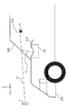
- FIG. 1 is a schematic diagram illustrating a moving body on which the head-up display according to the present disclosure is mounted.
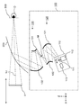
- FIG. 2 is a schematic diagram showing an optical cross section showing the configuration of the head-up display in the first embodiment.
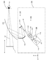
- FIG. 3 is a schematic diagram showing an optical cross section showing the configuration of the head-up display in the second embodiment.
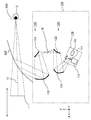
- FIG. 4 is a schematic diagram showing an optical cross section showing the configuration of the head-up display in the third embodiment.
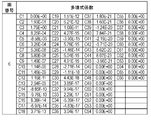
- FIG. 5 is a diagram showing the decentering data of each surface in the optical system of Example 1 (corresponding to Embodiment 1).
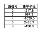
- FIG. 6 is a diagram showing the radius of curvature of each surface in the optical system of Example 1 (corresponding to Embodiment 1).
- FIG. 1 is a schematic diagram illustrating a moving body on which the head-up display according to the present disclosure is mounted.
- FIG. 2 is a schematic diagram showing an optical cross section showing the configuration of the head-up display in the first embodiment.
- FIG. 3 is a schematic
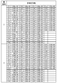
- FIG. 7 is a diagram showing data on the shape of a free-form surface in the optical system of Example 1 (corresponding to Embodiment 1).
- FIG. 8 is a diagram showing data on the shape of a free-form surface in the optical system of Example 1 (corresponding to Embodiment 1).
- FIG. 9 is a diagram showing data on the shape of a free-form surface in the optical system of Example 1 (corresponding to Embodiment 1).
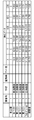
- FIG. 10 is a diagram showing decentering data of each surface in the optical system of Example 2 (corresponding to Embodiment 1).
- FIG. 11 is a diagram showing the radius of curvature of each surface in the optical system of Example 2 (corresponding to Embodiment 1).
- FIG. 12 is a diagram showing data on the shape of a free-form surface in the optical system of Example 2 (corresponding to Embodiment 1).
- FIG. 13 is a diagram showing data on the shape of a free-form surface in the optical system of Example 2 (corresponding to Embodiment 1).
- FIG. 14 is a diagram showing data on the shape of a free-form surface in the optical system of Example 2 (corresponding to Embodiment 1).
- FIG. 15 is a diagram illustrating data of the head-up display of Examples 1 and 2.
- FIG. 1 is a schematic diagram showing a cross section of a vehicle 200 equipped with a head-up display 100 according to the present disclosure.
- the head-up display 100 is disposed inside the dashboard 210 below the windshield 220 of the vehicle 200.
- the observer D recognizes an image projected from the head-up display 100 as a virtual image I.
- FIG. 2 is a schematic diagram showing an optical cross section for explaining the head-up display 100 according to the first embodiment.
- the head-up display 100 includes a display device 110, a relay optical system 120, and a projection optical system 130.
- the head-up display 100 reflects an image displayed by the display device 110 through the windshield 220 and guides it to the viewpoint region 300 (sometimes referred to as an eyebox) of the observer D to present a virtual image I. is there.
- the optical path of the display image on the screen 111 that forms the center of the virtual image I is defined as a reference ray Lc.
- the reference light beam Lc visually recognized by the observer D actually arrives at the observer D from the display device 110 via the optical system.
- the light beam corresponding to the reference light beam Lc emitted from the center of the virtual image I until reaching the observer D from the display device 110 is also expressed as the reference light beam Lc.
- the optical paths corresponding to these rays are also expressed as reference rays Lc.
- the viewpoint of the observer D is at the center of the viewpoint area 300.
- the display device 110 includes a screen 111, a drive unit 112 that drives the screen 111, and a scanning laser 113.
- display image information is controlled by a control unit such as a microcomputer (not shown).
- a control unit such as a microcomputer (not shown).
- As the display image information it is possible to display various information such as a road progress guidance display, a distance to the vehicle ahead, a remaining battery level of the car, and the current vehicle speed.
- a light source of the display device 110 a projector or a scanning laser that projects an image on the screen 111 is used.
- the scanning laser 113 forms a display image by scanning the surface of the screen 111.
- the drive unit 112 is a drive device that moves the screen 111 along the reference light beam Lc.
- the distance from the observer D to the virtual image I can be adjusted by moving the screen 111 along the reference light beam Lc by the driving unit 112.
- the virtual image I can be moved away from the observer D by moving the screen 111 away from the relay optical system 120.
- the driving unit 112 moves according to the scanning position on the screen 111 of the scanning laser 113.
- the virtual image I can be drawn on an arbitrary plane regardless of the emission angle of the reference light beam Lc of the screen 111.
- the virtual image I can be drawn on a plane inclined with respect to the observer D by synchronizing the drawing period of the scanning laser 113 and the oscillation period of the screen 111.
- the virtual image I can be displayed in three dimensions by moving the screen 111 back and forth in the direction of the reference light beam Lc at several tens of Hz.
- the movement amount of the intermediate image M is larger than the movement amount of the screen 111. This is because the lateral magnification ⁇ of the relay optical system 120 has an enlargement effect larger than 1. At this time, with respect to the amount of movement of the screen 111, the amount of movement of the intermediate image M is moved by beta 2 times.
- the aerial image M is not formed on the projection surface that forms an image in the air and diffusely reflects it.
- the driving unit 112 may not only move the screen 111 in the optical axis direction but also may be configured to rotate or tilt the screen 111.
- the relay optical system 120 includes a first mirror 121 and a second mirror 122.
- the relay optical system 120 forms an intermediate image M by reflecting the image displayed on the screen 111 of the display device 110 through the first mirror 121 and further through the second mirror 122.
- the intermediate image M is formed larger than the image displayed on the screen 111. That is, even if the image displayed on the screen 111 is small, a large intermediate image M can be obtained. Thereby, the size of the screen 111 can be reduced. Further, since the intermediate image M is large, the magnification in the projection optical system 130 can be lowered. Thereby, the positive power of the 4th mirror of the projection optical system 130 can be weakened, and screen distortion can be suppressed. Specifically, it is desirable to set the power of the relay optical system 120 so as to satisfy the following condition (1).
- ⁇ The lateral magnification of the relay optical system 120.
- the intermediate image M does not need to be formed as a good point at the intermediate image position, and spherical aberration, coma aberration, field curvature, and astigmatism may occur.
- the projection optical system 130 includes a third mirror 131 and a fourth mirror 132.
- the projection optical system 130 projects the intermediate image M formed by the relay optical system 120 onto the windshield 220 by reflecting through the third mirror 131 and reflecting through the fourth mirror 132.
- the aerial image M is not formed on the projection surface that forms an image in the air and diffusely reflects it.
- the position of the display device 110 is disposed below the relay optical system 120 and the projection optical system 130. Further, the display surface of the screen 111 of the display device 110 is directed toward the first mirror 121. At this time, it is desirable that the reference light beam Lc emitted from the display device 110 is inclined with respect to the display surface of the screen 111. Thereby, stray light caused by external light entering the housing and reflected on the display surface of the display device 110 can be prevented.
- the screen 111 of the display device 110 is composed of an optical member having diffusion characteristics.
- a scanning laser 113 that projects an image onto the screen 111 is disposed behind the screen 111.
- the first mirror 121 is arranged above the display device 110 and on the viewer D side.
- the reflection surface of the first mirror 121 is decentered so as to reflect an image displayed on the display device 110 in a direction in which the image is reflected on the second mirror 122.
- the second mirror 122 is disposed below the first mirror 121 and on the virtual image I side.
- the reflection surface of the second mirror 122 is decentered so that the light beam reflected by the first mirror 121 is reflected in the direction reflected by the third mirror 131.
- the third mirror 131 is disposed above the first mirror 121.
- the reflection surface of the third mirror 131 is decentered so that the light beam reflected by the second mirror 122 is reflected in the direction in which it is reflected on the fourth mirror 132.
- the fourth mirror 132 is disposed on the virtual image I side with respect to the third mirror 131.
- the reflection surface of the fourth mirror 132 is decentered so as to reflect the reflected light from the third mirror 131 in the direction reflected on the windshield 220.
- the interval of the reference beam Lc from the first mirror 121 to the second mirror 122 is shorter than the interval of the reference beam Lc from the third mirror 131 to the fourth mirror 132.
- the size of the head-up display 100 can be reduced.
- the interval of the reference light beam Lc from the screen 111 to the first mirror 121 is shorter than the interval of the reference light beam Lc from the first mirror 121 to the intermediate image M.
- the first mirror 121 can be reduced in size, and the size of the head-up display 100 can also be reduced.
- the upper end of the reflection surface of the first mirror 121 is positioned above the lower end of the reflection surface of the fourth mirror 132 in the vertical direction. By doing so, the size of the head-up display 100 can be reduced.
- the difference in the emission angle from the screen 111 can be reduced from the center to the periphery of the display image area of the screen 111.
- fluctuate in the direction of the reference ray Lc can be suppressed.
- the reflecting surface of the first mirror 121 has a concave shape.
- the reflection surface of the second mirror 122 has a convex shape.
- the second mirror 122 has a convex shape, it is possible to satisfactorily correct asymmetric eccentric distortion generated in the first mirror 121.
- by forming the first mirror 121 into a concave shape it is possible to perform a condensing function for intermediately forming an image on the screen 111.
- either the first mirror 121 or the second mirror 122 may be a free-form surface, and the other may be a plane mirror.
- the relay optical system 120 is not limited to the first mirror 121 and the second mirror 122, and may be constituted by a refractive optical element such as a lens element having the same function, or the first mirror 121 or the second mirror 122. You may comprise only the mirror 121. FIG.
- the reflecting surface of the third mirror 131 has a convex shape.
- the reflection surface of the fourth mirror 132 has a concave shape.
- the power of the first mirror 121 is the largest among the relay optical system 120 and the projection optical system 130. Thereby, size reduction of the relay optical system 120 can be achieved.
- the first mirror 121, the second mirror 122, the third mirror 131, and the fourth mirror 132 adopt a free curved surface shape. This is to correct the distortion of the virtual image caused by the reflection so that a good virtual image I can be seen in the entire viewpoint area 300.
- the head-up display 100 includes the display device 110, the relay optical system 120, and the projection optical system 130.
- the image formed by the relay optical system 120 is larger than the display image that the display device 110 displays on the screen 111. Thereby, size reduction of the display device 110 is realizable. Further, by including the relay optical system 120, the positive power of the projection optical system 130 can be suppressed while the screen 111 is downsized while the screen distortion is corrected well.
- Embodiment 2 will be described with reference to FIG.
- the configuration of the relay optical system 140 is different from the relay optical system 120 of the first embodiment, and other configurations are the same as those of the first embodiment. Therefore, hereinafter, different points will be mainly described, and description of similar configurations will be omitted.
- FIG. 3 is a schematic diagram showing an optical cross section for explaining the head-up display 100 according to the second embodiment.
- the relay optical system 140 in the second embodiment includes a first lens 141, a second lens 142, and a third lens 143.
- the relay optical system 140 has a positive power as a whole.
- the first lens 141 has a spherical shape having a positive power.
- the second lens 142 has a spherical shape having a negative power.
- the third lens 143 has a spherical shape having positive power.
- the surface shape of any of the first lens 141, the second lens 142, and the third lens 143 may be a free-form surface.
- the relay optical system 140 is not limited to the first lens 141, the second lens 142, and the third lens 143, and may be configured by four or more lenses.
- the image displayed on the screen 111 of the display device 110 is refracted through the first lens 141, then refracted through the second lens 142, and then refracted through the third lens 143 to be an intermediate image. M is formed. At this time, the intermediate image M is formed larger than the image displayed on the screen 111.
- the power of the relay optical system 140 is set so as to satisfy the following condition (1).
- ⁇ The lateral magnification of the relay optical system 140.
- the projection optical system 130 includes a third mirror 131 and a fourth mirror 132.
- the projection optical system 130 projects the intermediate image M formed by the relay optical system onto the windshield 220 by reflecting through the third mirror 131 and further through the fourth mirror 132.
- the position of the display device 110 is disposed below the relay optical system 140 and the projection optical system 130.
- the display surface of the screen 111 of the display device 110 is directed toward the first lens 141.
- it is desirable that the reference light beam Lc emitted from the display device 110 is inclined with respect to the display surface of the screen 111.
- the screen 111 of the display device 110 is composed of an optical member having diffusion characteristics.
- a scanning laser 113 that projects an image onto the screen 111 is disposed behind the screen 111.
- the third mirror 131 is disposed above the relay optical system 140.
- the reflection surface of the third mirror 131 is decentered so that the light beam emitted from the third lens 143 is reflected in the direction reflected on the fourth mirror 132.
- the fourth mirror 132 is disposed on the virtual image I side (the positive direction of the X axis) with respect to the third mirror 131.
- the reflection surface of the fourth mirror 132 is eccentric in the direction in which the reflected light from the third mirror 131 is projected onto the windshield 220.
- the head-up display 100 includes the display device 110, the relay optical system 140, and the projection optical system 130.
- the image formed by the relay optical system 140 is larger than the display image that the display device 110 displays on the screen 111. Thereby, size reduction of the display device 110 is realizable. Further, by including the relay optical system 140, it is possible to suppress the positive power of the projection optical system 130 while reducing the size of the screen 111 while favorably correcting the screen distortion.
- Embodiment 3 will be described with reference to FIG.
- the arrangement position of the relay optical system 120 is different from that in the first embodiment, and other configurations are the same as those in the first embodiment. Therefore, hereinafter, different points will be mainly described, and description of similar configurations will be omitted.
- the position of the display device 110 is arranged below the relay optical system 120 and the projection optical system 130. Further, the display surface of the screen 111 of the display device 110 is directed toward the first mirror 121. At this time, it is desirable that the reference light beam Lc emitted from the display device 110 is inclined with respect to the display surface of the screen 111. Thereby, stray light caused by external light such as sunlight entering the housing of the head-up display 100 and reflected on the display surface of the screen 111 can be prevented.
- the screen 111 is composed of an optical member having diffusion characteristics.
- a scanning laser 113 that projects an image onto the screen 111 is disposed behind the screen 111.
- the first mirror 121 is disposed above the display device 110 in the vertical direction of the vehicle 200 (positive direction of the Z axis) and on the virtual image I side (positive direction of the X axis), and is displayed on the display device 110.
- the reflection surface is decentered in the direction in which the image to be reflected on the second mirror 122 is reflected.
- the second mirror 122 is arranged above the first mirror 121 and on the viewer D side (the negative direction of the X axis), and reflects the light beam reflected by the first mirror 121 in the direction in which it is reflected on the third mirror 131.
- the surface is eccentric.
- the interval of the reference beam Lc between the first mirror 121 and the second mirror 122 is shorter than the interval of the reference beam Lc between the third mirror 131 and the fourth mirror 132.
- the size of the head-up display 100 can be reduced.
- the interval between the reference light beam Lc from the screen 111 and the first mirror 121 is shorter than the interval between the reference light beam Lc from the first mirror 121 to the intermediate image M.
- the first mirror 121 can be reduced in size, and the size of the head-up display 100 can also be reduced.
- the exit side of the screen 111 faces the traveling direction of the vehicle 200. By doing so, the scanning laser 113 can be disposed on the viewer D side, and interference with the structure in front of the vehicle can be avoided.
- Embodiments 1 to 3 have been described as examples of the technology disclosed in the present application.
- the technology in the present disclosure is not limited to this, and can also be applied to embodiments that have been changed, replaced, added, omitted, and the like.
- the display device 110 has been described using a projector or a scanning laser that projects an image on the screen 111.
- a liquid crystal display device Liquid Crystal Display
- organic light emitting diode electrospray
- a plasma display or the like can be used as the screen 111 without using a projector or a scanning laser.
- the drive unit 112 is a drive device that moves the screen 111 along the reference light beam Lc.
- either the third mirror 131 or the fourth mirror 132 may be a free-form surface, and the other may be a plane mirror.
- the projection optical system 130 is not limited to the third mirror 131 and the fourth mirror 132, and may be configured by a refractive optical element such as a lens element having the same function, or a fourth one. You may comprise only the mirror 132. FIG.
- the third mirror 131 has been described using a mirror having a rotationally asymmetric shape.
- the third mirror 131 has a so-called bowl-shaped surface shape in which the sign of curvature differs between the X direction and the Y direction. May be.
- the second mirror 122 has been described using a mirror having a rotationally asymmetric shape.
- the second mirror 122 has a so-called bowl-shaped surface shape with different signs of curvature in the X direction and the Y direction. May be.
- the unit of length in the table is (mm), and the unit of angle is (degree).
- the free-form surface is defined by the following formula 1.
- z is the sag amount at the position (x, y) from the axis defining the surface.
- r is the radius of curvature at the origin of the axis defining the surface.
- c is the curvature at the origin of the axis defining the surface.
- k is the conic constant, corresponding to C 1 polynomial coefficients.
- C j is a coefficient of the monomial x m y n .
- m and n are integers of 0 or more.
- the reference coordinate origin is the center of the image (display surface) displayed on the display device 110.
- the horizontal direction of the display surface is shown as the X axis, the vertical direction as the Y axis, and the direction perpendicular to the display surface as the Z axis.
- ADE means the amount of rotation of the mirror or lens from the Z axis direction to the Y axis direction around the X axis.
- BDE means the amount of rotation about the Y axis from the X axis direction to the Z axis direction.
- CDE means the amount of rotation about the Z axis from the X axis direction to the Y axis direction.
- FIGS. 5 to 9 are data of the optical system of the head-up display 100 according to Numerical Example 1 (Embodiment 1).
- Numerical Example 1 adopts the configuration of the first embodiment. Specific optical system data are shown in FIGS.
- FIG. 5 shows the decentration data of each surface in each optical element of the head-up display 100.
- FIG. 6 shows the radius of curvature of each surface.
- 7 to 9 are polynomial coefficients representing the shape of the free-form surface.
- FIGS. 10 to 14 show optical system data of the head-up display 100 according to Numerical Example 2 (Embodiment 1).
- Numerical Example 2 adopts the configuration of the first embodiment. Specific optical data are shown in FIGS.
- FIG. 10 shows the decentration data of each surface in each optical element of the head-up display 100.
- FIG. 11 shows the radius of curvature.
- 12 to 14 are polynomial coefficients representing the shape of a free-form surface.
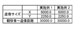
- FIG. 15 is data showing the size of the virtual image I of Examples 1 and 2 and the distance from the observer D to the virtual image I.
- Table 1 shows the corresponding values of conditional expression (1) of the first and second embodiments.
- the present disclosure can be applied to a head-up display that projects onto a reflective transmission member. Specifically, the present disclosure is applicable to a head-up display mounted on a moving body having a windshield.
Abstract
Cet affichage tête haute (100) projette une image sur un pare-brise transparent (220) et rend une image virtuelle visible pour un observateur. L'affichage tête haute (100) est pourvu d'un dispositif d'affichage (110), d'un système optique de relais (120), et d'un système optique de projection (130). Le dispositif d'affichage (110) affiche une image. Le système optique de relais (120) forme une image intermédiaire de l'image affichée par le dispositif d'affichage (110). Le système optique de projection (130) réfléchit l'image intermédiaire formée par le système optique de relais (120) et projette ladite image intermédiaire sur le pare-brise (220).
Priority Applications (3)
| Application Number | Priority Date | Filing Date | Title |
|---|---|---|---|
| EP16813967.3A EP3276396B1 (fr) | 2015-06-26 | 2016-06-23 | Affichage tête haute et corps mobile équipé d'un affichage tête haute |
| JP2017524643A JP6650584B2 (ja) | 2015-06-26 | 2016-06-23 | ヘッドアップディスプレイおよびヘッドアップディスプレイを搭載した移動体 |
| US15/728,543 US10281722B2 (en) | 2015-06-26 | 2017-10-10 | Head-up display and moving body equipped with head-up display |
Applications Claiming Priority (2)
| Application Number | Priority Date | Filing Date | Title |
|---|---|---|---|
| JP2015128943 | 2015-06-26 | ||
| JP2015-128943 | 2015-06-26 |
Related Child Applications (1)
| Application Number | Title | Priority Date | Filing Date |
|---|---|---|---|
| US15/728,543 Continuation-In-Part US10281722B2 (en) | 2015-06-26 | 2017-10-10 | Head-up display and moving body equipped with head-up display |
Publications (1)
| Publication Number | Publication Date |
|---|---|
| WO2016208195A1 true WO2016208195A1 (fr) | 2016-12-29 |
Family
ID=57584791
Family Applications (1)
| Application Number | Title | Priority Date | Filing Date |
|---|---|---|---|
| PCT/JP2016/003029 WO2016208195A1 (fr) | 2015-06-26 | 2016-06-23 | Affichage tête haute et corps mobile équipé d'un affichage tête haute |
Country Status (4)
| Country | Link |
|---|---|
| US (1) | US10281722B2 (fr) |
| EP (1) | EP3276396B1 (fr) |
| JP (1) | JP6650584B2 (fr) |
| WO (1) | WO2016208195A1 (fr) |
Cited By (10)
| Publication number | Priority date | Publication date | Assignee | Title |
|---|---|---|---|---|
| JP2017181644A (ja) * | 2016-03-29 | 2017-10-05 | 矢崎総業株式会社 | 車両用投影表示装置 |
| WO2018199245A1 (fr) * | 2017-04-28 | 2018-11-01 | コニカミノルタ株式会社 | Dispositif d'affichage d'image virtuelle et système d'affichage de corps mobile |
| WO2018199246A1 (fr) * | 2017-04-28 | 2018-11-01 | コニカミノルタ株式会社 | Dispositif d'affichage d'image virtuelle et système d'affichage pour corps mobile |
| WO2019044595A1 (fr) * | 2017-08-31 | 2019-03-07 | 富士フイルム株式会社 | Dispositif d'affichage tête haute |
| JP2020204773A (ja) * | 2017-04-03 | 2020-12-24 | 三菱電機株式会社 | 虚像表示装置 |
| JPWO2019163171A1 (ja) * | 2018-02-23 | 2021-04-15 | パナソニックIpマネジメント株式会社 | ヘッドアップディスプレイおよびヘッドアップディスプレイを搭載した移動体 |
| US11402630B2 (en) | 2017-12-11 | 2022-08-02 | Panasonic Intellectual Property Management Co., Ltd. | Head-up display and moving body with head-up display mounted thereon |
| US11579445B2 (en) | 2017-12-11 | 2023-02-14 | Panasonic Intrllectual Property Management Co., Ltd. | Head-up display and moving body with head-up display mounted thereon |
| WO2023047678A1 (fr) | 2021-09-22 | 2023-03-30 | 日亜化学工業株式会社 | Unité de source de lumière et dispositif d'affichage vidéo |
| WO2023234194A1 (fr) * | 2022-05-30 | 2023-12-07 | 日亜化学工業株式会社 | Unité de source de lumière, dispositif d'affichage vidéo et automobile |
Families Citing this family (4)
| Publication number | Priority date | Publication date | Assignee | Title |
|---|---|---|---|---|
| US10788665B2 (en) * | 2015-10-09 | 2020-09-29 | Maxell, Ltd. | Projection optical system and head-up display device |
| EP3825748A1 (fr) * | 2019-11-21 | 2021-05-26 | Ricoh Company, Ltd. | Dispositif de réflexion de lumière et objet mobile |
| WO2022085658A1 (fr) * | 2020-10-20 | 2022-04-28 | 日本精機株式会社 | Dispositif d'affichage tête haute |
| CN112731667A (zh) * | 2021-01-05 | 2021-04-30 | 业成科技(成都)有限公司 | 投影装置及投影方法 |
Citations (2)
| Publication number | Priority date | Publication date | Assignee | Title |
|---|---|---|---|---|
| JP2009150947A (ja) * | 2007-12-19 | 2009-07-09 | Hitachi Ltd | 車両用ヘッドアップディスプレイ装置 |
| JP2013061554A (ja) * | 2011-09-14 | 2013-04-04 | Ricoh Co Ltd | 画像形成装置、画像形成装置を搭載した車両 |
Family Cites Families (11)
| Publication number | Priority date | Publication date | Assignee | Title |
|---|---|---|---|---|
| US4669810A (en) * | 1984-02-03 | 1987-06-02 | Flight Dynamics, Inc. | Head up display system |
| DE69325607T2 (de) * | 1992-04-07 | 2000-04-06 | Raytheon Co | Breites spektrales Band virtuelles Bildanzeige optisches System |
| JPH07159718A (ja) * | 1993-12-02 | 1995-06-23 | Fujitsu Ltd | ヘッドアップディスプレイ |
| JPH08286140A (ja) * | 1995-04-11 | 1996-11-01 | Canon Inc | 画像表示装置 |
| JPH0965247A (ja) * | 1995-08-22 | 1997-03-07 | Olympus Optical Co Ltd | 映像表示装置 |
| US6902282B2 (en) * | 2002-03-22 | 2005-06-07 | Raytheon Company | Fast, wide-field-of-view, relayed multimirror optical system |
| JP4930071B2 (ja) * | 2007-01-23 | 2012-05-09 | セイコーエプソン株式会社 | 表示装置 |
| JP2010256867A (ja) * | 2009-03-30 | 2010-11-11 | Victor Co Of Japan Ltd | ヘッドアップディスプレイ及び画像表示方法 |
| DE102012214533B4 (de) * | 2012-08-15 | 2017-06-08 | Sypro Optics Gmbh | Head-up Display und Projektionsoptik für ein Head-up Display |
| JP6024452B2 (ja) * | 2012-12-28 | 2016-11-16 | 株式会社Jvcケンウッド | 画像表示装置 |
| DE102013203616B4 (de) * | 2013-03-04 | 2019-10-24 | Sypro Optics Gmbh | Vorrichtung zur Projektion eines Bildes in einen Anzeigebereich mit Schirm zur Zwischenbildanzeige |
-
2016
- 2016-06-23 JP JP2017524643A patent/JP6650584B2/ja active Active
- 2016-06-23 EP EP16813967.3A patent/EP3276396B1/fr active Active
- 2016-06-23 WO PCT/JP2016/003029 patent/WO2016208195A1/fr active Application Filing
-
2017
- 2017-10-10 US US15/728,543 patent/US10281722B2/en active Active
Patent Citations (2)
| Publication number | Priority date | Publication date | Assignee | Title |
|---|---|---|---|---|
| JP2009150947A (ja) * | 2007-12-19 | 2009-07-09 | Hitachi Ltd | 車両用ヘッドアップディスプレイ装置 |
| JP2013061554A (ja) * | 2011-09-14 | 2013-04-04 | Ricoh Co Ltd | 画像形成装置、画像形成装置を搭載した車両 |
Non-Patent Citations (1)
| Title |
|---|
| See also references of EP3276396A4 * |
Cited By (17)
| Publication number | Priority date | Publication date | Assignee | Title |
|---|---|---|---|---|
| JP2017181644A (ja) * | 2016-03-29 | 2017-10-05 | 矢崎総業株式会社 | 車両用投影表示装置 |
| JP7062038B2 (ja) | 2017-04-03 | 2022-05-02 | 三菱電機株式会社 | 虚像表示装置 |
| JP2020204773A (ja) * | 2017-04-03 | 2020-12-24 | 三菱電機株式会社 | 虚像表示装置 |
| WO2018199245A1 (fr) * | 2017-04-28 | 2018-11-01 | コニカミノルタ株式会社 | Dispositif d'affichage d'image virtuelle et système d'affichage de corps mobile |
| WO2018199246A1 (fr) * | 2017-04-28 | 2018-11-01 | コニカミノルタ株式会社 | Dispositif d'affichage d'image virtuelle et système d'affichage pour corps mobile |
| WO2019044595A1 (fr) * | 2017-08-31 | 2019-03-07 | 富士フイルム株式会社 | Dispositif d'affichage tête haute |
| JPWO2019044595A1 (ja) * | 2017-08-31 | 2020-04-09 | 富士フイルム株式会社 | ヘッドアップディスプレイ装置 |
| US11402630B2 (en) | 2017-12-11 | 2022-08-02 | Panasonic Intellectual Property Management Co., Ltd. | Head-up display and moving body with head-up display mounted thereon |
| US11579445B2 (en) | 2017-12-11 | 2023-02-14 | Panasonic Intrllectual Property Management Co., Ltd. | Head-up display and moving body with head-up display mounted thereon |
| US11852809B2 (en) | 2017-12-11 | 2023-12-26 | Panasonic Intellectual Property Management Co., Ltd. | Head-up display and moving body with head-up display mounted thereon |
| JPWO2019163171A1 (ja) * | 2018-02-23 | 2021-04-15 | パナソニックIpマネジメント株式会社 | ヘッドアップディスプレイおよびヘッドアップディスプレイを搭載した移動体 |
| US11428928B2 (en) | 2018-02-23 | 2022-08-30 | Panasonic Intellectual Property Management Co., Ltd. | Head-up display and mobile body equipped with head-up display |
| JP7162273B2 (ja) | 2018-02-23 | 2022-10-28 | パナソニックIpマネジメント株式会社 | ヘッドアップディスプレイおよびヘッドアップディスプレイを搭載した移動体 |
| US11789260B2 (en) | 2018-02-23 | 2023-10-17 | Panasonic Intellectual Property Management Co., Ltd. | Head-up display and mobile body equipped with head-up display and projection optical system |
| JP7365621B2 (ja) | 2018-02-23 | 2023-10-20 | パナソニックIpマネジメント株式会社 | 結像光学系および結像光学系を搭載した移動体 |
| WO2023047678A1 (fr) | 2021-09-22 | 2023-03-30 | 日亜化学工業株式会社 | Unité de source de lumière et dispositif d'affichage vidéo |
| WO2023234194A1 (fr) * | 2022-05-30 | 2023-12-07 | 日亜化学工業株式会社 | Unité de source de lumière, dispositif d'affichage vidéo et automobile |
Also Published As
| Publication number | Publication date |
|---|---|
| JPWO2016208195A1 (ja) | 2018-04-19 |
| EP3276396B1 (fr) | 2022-10-19 |
| US10281722B2 (en) | 2019-05-07 |
| US20180039077A1 (en) | 2018-02-08 |
| EP3276396A1 (fr) | 2018-01-31 |
| EP3276396A4 (fr) | 2018-04-04 |
| JP6650584B2 (ja) | 2020-02-19 |
Similar Documents
| Publication | Publication Date | Title |
|---|---|---|
| WO2016208195A1 (fr) | Affichage tête haute et corps mobile équipé d'un affichage tête haute | |
| US9958677B2 (en) | Head-up display and mobile object equipped with head-up display | |
| JP6630921B2 (ja) | ヘッドアップディスプレイおよびヘッドアップディスプレイを搭載した移動体 | |
| WO2016079926A1 (fr) | Affichage tête haute et véhicule | |
| JP6283826B2 (ja) | ヘッドアップディスプレイおよびヘッドアップディスプレイを搭載した移動体 | |
| JP6709906B2 (ja) | 画像投写装置 | |
| JP6225341B2 (ja) | ヘッドアップディスプレイおよびヘッドアップディスプレイを搭載した移動体 | |
| JP6675059B2 (ja) | ヘッドアップディスプレイおよびヘッドアップディスプレイを搭載した移動体 | |
| JP7365621B2 (ja) | 結像光学系および結像光学系を搭載した移動体 | |
| JP2017068251A (ja) | ヘッドアップディスプレイおよびヘッドアップディスプレイを搭載した車両 | |
| JPWO2019116730A1 (ja) | ヘッドアップディスプレイおよびヘッドアップディスプレイを搭載した移動体 | |
| JP6830182B2 (ja) | 画像投写装置 | |
| WO2018186149A1 (fr) | Système d'affichage tête haute, et objet mobile équipé du système d'affichage tête haute | |
| JPWO2019116731A1 (ja) | ヘッドアップディスプレイおよびヘッドアップディスプレイを搭載した移動体 | |
| JP2016012129A (ja) | 車両用投影表示装置 | |
| JP2019179065A (ja) | ヘッドアップディスプレイ装置 |
Legal Events
| Date | Code | Title | Description |
|---|---|---|---|
| 121 | Ep: the epo has been informed by wipo that ep was designated in this application |
Ref document number: 16813967 Country of ref document: EP Kind code of ref document: A1 |
|
| ENP | Entry into the national phase |
Ref document number: 2017524643 Country of ref document: JP Kind code of ref document: A |
|
| REEP | Request for entry into the european phase |
Ref document number: 2016813967 Country of ref document: EP |
|
| NENP | Non-entry into the national phase |
Ref country code: DE |