WO2016204203A1 - ゲートバルブ - Google Patents
ゲートバルブ Download PDFInfo
- Publication number
- WO2016204203A1 WO2016204203A1 PCT/JP2016/067859 JP2016067859W WO2016204203A1 WO 2016204203 A1 WO2016204203 A1 WO 2016204203A1 JP 2016067859 W JP2016067859 W JP 2016067859W WO 2016204203 A1 WO2016204203 A1 WO 2016204203A1
- Authority
- WO
- WIPO (PCT)
- Prior art keywords
- valve
- valve body
- base material
- gate
- valve seat
- Prior art date
- Legal status (The legal status is an assumption and is not a legal conclusion. Google has not performed a legal analysis and makes no representation as to the accuracy of the status listed.)
- Ceased
Links
Images


Classifications
-
- C—CHEMISTRY; METALLURGY
- C23—COATING METALLIC MATERIAL; COATING MATERIAL WITH METALLIC MATERIAL; CHEMICAL SURFACE TREATMENT; DIFFUSION TREATMENT OF METALLIC MATERIAL; COATING BY VACUUM EVAPORATION, BY SPUTTERING, BY ION IMPLANTATION OR BY CHEMICAL VAPOUR DEPOSITION, IN GENERAL; INHIBITING CORROSION OF METALLIC MATERIAL OR INCRUSTATION IN GENERAL
- C23C—COATING METALLIC MATERIAL; COATING MATERIAL WITH METALLIC MATERIAL; SURFACE TREATMENT OF METALLIC MATERIAL BY DIFFUSION INTO THE SURFACE, BY CHEMICAL CONVERSION OR SUBSTITUTION; COATING BY VACUUM EVAPORATION, BY SPUTTERING, BY ION IMPLANTATION OR BY CHEMICAL VAPOUR DEPOSITION, IN GENERAL
- C23C14/00—Coating by vacuum evaporation, by sputtering or by ion implantation of the coating forming material
- C23C14/22—Coating by vacuum evaporation, by sputtering or by ion implantation of the coating forming material characterised by the process of coating
- C23C14/56—Apparatus specially adapted for continuous coating; Arrangements for maintaining the vacuum, e.g. vacuum locks
-
- F—MECHANICAL ENGINEERING; LIGHTING; HEATING; WEAPONS; BLASTING
- F16—ENGINEERING ELEMENTS AND UNITS; GENERAL MEASURES FOR PRODUCING AND MAINTAINING EFFECTIVE FUNCTIONING OF MACHINES OR INSTALLATIONS; THERMAL INSULATION IN GENERAL
- F16K—VALVES; TAPS; COCKS; ACTUATING-FLOATS; DEVICES FOR VENTING OR AERATING
- F16K1/00—Lift valves or globe valves, i.e. cut-off apparatus with closure members having at least a component of their opening and closing motion perpendicular to the closing faces
- F16K1/32—Details
- F16K1/34—Cutting-off parts, e.g. valve members, seats
-
- F—MECHANICAL ENGINEERING; LIGHTING; HEATING; WEAPONS; BLASTING
- F16—ENGINEERING ELEMENTS AND UNITS; GENERAL MEASURES FOR PRODUCING AND MAINTAINING EFFECTIVE FUNCTIONING OF MACHINES OR INSTALLATIONS; THERMAL INSULATION IN GENERAL
- F16K—VALVES; TAPS; COCKS; ACTUATING-FLOATS; DEVICES FOR VENTING OR AERATING
- F16K51/00—Other details not peculiar to particular types of valves or cut-off apparatus
- F16K51/02—Other details not peculiar to particular types of valves or cut-off apparatus specially adapted for high-vacuum installations
Definitions
- the present invention relates to a gate valve that sandwiches and closes a flexible belt-like base material.
- a thin film base material when a thin film base material is manufactured, a flexible belt-shaped base material made of resin is intermittently conveyed by roll-to-roll, and a thin film is patterned on the base material.
- Thin film patterning is performed in a chamber provided for each thin film.
- the substrate is transported between the chambers. Between adjacent chambers, for example, a gate valve for maintaining the environment in each chamber at a high vacuum is provided (see Patent Documents 1 to 7).
- the valve body is a resin-made flexible member
- the valve body is seated on the valve seat through the base material, and the valve body and the valve seat sandwich the base material between the valve body and the valve closed state.
- the base material remains in close contact with the valve body, and the base material may not be transported after the valve is opened.
- the gate valve is increased in size, and the opening / closing time of the gate valve is increased, resulting in a decrease in productivity.
- the present invention has been made in view of the above circumstances, and an object thereof is to provide a gate valve capable of suitably peeling a base material from a valve body when the valve is opened.
- a gate valve provided at an inlet / outlet of the base material in a chamber in which a belt-like base material having flexibility is conveyed, and opening / closing the inlet / outlet; a valve seat provided on one side of the base material; and the base A valve body provided on the other surface side of the material, wherein the valve body is a flexible member, and the valve body is seated on the valve seat so that the valve body and the valve seat
- the part that contacts the other surface of the base material in the seated state of the valve body is: A gate valve that moves in a direction different from a direction in which the valve body is separated.
- the valve body has a cylindrical shape, and when the valve body is separated from the valve seat, the valve body is moved in a direction away from the valve seat while rotating.
- the valve body includes a valve body base portion and a movable portion movable relative to the valve body base portion. When the valve body is seated on the valve seat, the valve body base portion and the movable portion are When the valve body comes into contact with the base material and moves away from the valve seat, the movable portion moves away from the valve body base while the valve body base moves away from the valve seat. 2.
- the gate valve according to 1 above wherein the gate valve moves relative to the first valve. 4). When the valve body separates from the valve seat, the valve body moves in a direction along the other surface of the base material while moving in a direction away from the valve seat. 2.
- the base material can be suitably peeled off from the valve body when the valve is opened.
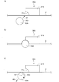
- FIG. 1 is a figure which shows a valve opening state
- (a) is a figure which shows a valve opening state
- (b) is a figure which shows a valve closing state
- (c) shows valve opening operation
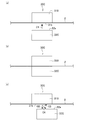
- FIG. 2nd embodiment of this invention is a figure which shows a valve opening state
- (b) is a figure which shows a valve closing state
- (c) shows valve opening operation
- FIG. 1 It is a schematic diagram which shows the gate valve which concerns on 3rd embodiment of this invention, (a) is a figure which shows a valve opening state, (b) is a figure which shows a valve closing state, (c) shows valve opening operation
- FIG. 1 is a schematic diagram which shows the gate valve which concerns on 3rd embodiment of this invention.
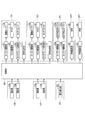
- FIG. 1 is a schematic diagram showing a thin film substrate manufacturing apparatus according to an embodiment of the present invention.
- FIG. 2 is a block diagram showing a thin film substrate manufacturing apparatus according to an embodiment of the present invention.
- a thin film substrate manufacturing apparatus 1 is an apparatus for manufacturing a thin film substrate by patterning a thin film on a substrate 2.
- the thin film substrate manufacturing apparatus 1 includes thin film forming units 10X and 10Y, a meandering correction unit 20, and gate valves 30X and 30Y. Further, as shown in FIG. 2, the thin film substrate manufacturing apparatus 1 includes a roller driving unit 41, a mask driving unit 42, a touch plate driving unit 43, and a meandering correction unit 20 provided for each of the thin film forming units 10X and 10Y.
- the roller drive parts 44a and 44b provided, the valve body drive part 45 provided for every gate valve 30X and 30Y, and the control part 50 which controls these each drive part are provided.
- the thin film base material manufacturing apparatus 1 may be provided with three or more thin film formation parts, and may be provided with the formation part which forms films other than the thin film formed into a pattern.
- the method of forming a thin film on the base material 2 is not limited to what is described later.
- the thin film forming portions 10 ⁇ / b> X and 10 ⁇ / b> Y are formed by patterning a thin film on a flexible belt-like substrate 2. These thin film forming portions 10X and 10Y are provided in order of the thin film forming portion 10X and the thin film forming portion 10Y from the upstream side.
- Each of the thin film forming units 10X and 10Y includes a chamber 11, a driving roller 12a, a touch roller 12b, photographing units 16a and 16b, a material emitting unit 17, and a mask 18. Note that the inside of the chamber 11 of the thin film forming units 10X and 10Y can be maintained at a high vacuum by a vacuum suction unit (not shown).
- the downstream end of the chamber 11 of the thin film forming unit 10X and the upstream end of the chamber 11 of the thin film forming unit 10Y communicate with each other so that the substrate 2 can be conveyed.
- the driving roller 12 a is provided in the chamber 11.
- the touch roller 12 b is a driven roller provided at a position facing the drive roller 12 in the chamber 11.
- the substrate 2 is sandwiched between the drive roller 12a and the touch roller 12b.
- the control unit 50 shown in FIG. 2 controls the roller driving unit 41 to rotate the driving roller 12a and convey the base material 2 from the upstream side to the downstream side.
- the imaging units 16 a and 16 b are cameras provided on the downstream side of the driving roller 12 a in the chamber 11, and are provided on a marker (not shown) and a mask 18 provided on the substrate 2. A marker (not shown) provided on the camera is photographed, and the photographing result is output to the control unit 50.
- the material emitting unit 17 is provided on the downstream side of the driving roller 12 a in the chamber 11 and below the base material 2.
- the control unit 50 shown in FIG. 2 controls the material emitting unit 17 to emit a thin film material (for example, evaporated material) to the lower surface of the substrate 2 through the mask 18.
- the mask 18 is provided on the downstream side of the drive roller 12 a in the chamber 11 and below the base material 2 and between the base material 2 and the material emitting portion 17.
- the control unit 50 shown in FIG. 2 moves the mask 18 by controlling the mask driving unit 42.
- the touch plate 19 is provided on the downstream side of the drive roller 12 a in the chamber 11 and at a position facing the mask 18 through the base material 2.
- the control unit 50 shown in FIG. 2 moves the touch plate 19 by controlling the touch plate driving unit 43.
- the meandering correction unit 20 corrects the meandering of the base material 2.
- the meandering correction unit 20 is provided on the downstream side of the thin film forming unit 10Y.
- the meandering correction unit 20 includes a chamber 21, driven rollers 21a, 21b, 21c, and 21d, meandering correction rollers 22a and 22b, and a meandering detection unit 23.
- the driven rollers 21 a, 21 b, 21 c, 21 d are provided in the chamber 21.
- the upper surface of the substrate 2 is wound around the driven rollers 21a and 21c, and the lower surface of the substrate 2 is wound around the driven rollers 21b and 21d.
- the meandering correction rollers 22 a and 22 b are driven rollers provided between the driven rollers 21 b and 21 c in the chamber 21.
- the upper surface of the base material 2 is wound around the meandering correction rollers 22a and 22b.
- the meandering detection unit 23 is a capacitance sensor provided between the meandering correction rollers 22a and 22b in the chamber 21, detects the position of the base material 2 (specifically, the position in the width direction), and controls the detection result. Output to 50.
- the control unit 50 shown in FIG. 2 drives the roller driving units 44a and 44b based on the detection result of the meandering detection unit 23, thereby tilting the meandering correction rollers 22a and 22b in the axial direction with respect to the conveyance direction of the base material 2. Change and correct the meandering of the substrate 2.
- the gate valves 30X and 30Y are provided between adjacent chambers, and are opened (pseudo-sealed) by sandwiching the base material 2 and sealing (pseudo-sealing) the base material 2. It is a valve that can be switched between a closed valve state that maintains the vacuum state.
- the gate valve 30 ⁇ / b> X is provided between the chamber 11 of the thin film forming unit 10 ⁇ / b> X and a chamber upstream of the chamber 11. That is, the gate valve 30X is a valve capable of sealing the inlet of the base material 2 in the thin film forming unit 10X.
- the gate valve 30 ⁇ / b> Y is provided between the chamber 11 of the thin film forming unit 10 ⁇ / b> Y and the chamber 21 of the meandering correction unit 20. That is, the gate valve 30Y is a valve capable of sealing the outlet of the base material 2 in the thin film forming unit 10Y (in other words, the inlet of the base material 2 in the chamber 21 of the meandering correction unit 20).
- the control part 50 shown in FIG. 2 moves the valve body 32 by controlling the valve body drive part 45, and switches the gate valves 30X and 30Y between the valve opening state and the valve closing state.
- the control unit 50 rotates the driving roller 12a by controlling the roller driving unit 41 of the thin film forming units 10X and 10Y in a state where the gate valves 30X and 30Y are opened, and the base material 2 is moved from the upstream side. After transporting to the downstream side by a predetermined distance, the drive roller 12a is stopped and the base material 2 is stopped (base material transport process).
- control unit 50 controls the valve body driving unit 45 of the gate valves 30X and 30Y to close the gate valves 30X and 30Y, and the inlet of the base material 2 and the thin film in the chamber 11 of the thin film forming unit 10X.
- the outlet of the base material 2 in the chamber 12 of the forming unit 10Y is sealed (valve closing step).
- the control unit 50 moves the mask 18 to control the mask 18 and the base material by controlling the mask driving unit 42 based on the imaging results of the imaging units 16a and 16b in each of the thin film forming units 10X and 10Y. 2, the mask 18, the base material 2, and the touch plate 19 are brought into close contact with each other by controlling the mask driving unit 42 and the touch plate driving unit 43.
- the control unit 50 controls the material emitting unit 17 in each of the thin film forming units 10X and 10Y to emit the material of the thin film to the lower surface of the substrate 2 through the mask 18, and the patterned thin film Is formed on the upper surface of the substrate 2 (for example, an evaporated organic material is deposited on the lower surface of the substrate 2) (thin film patterning step).
- the control unit 50 controls the mask driving unit 42 and the touch plate driving unit 43 to release the close contact between the mask 18, the base material 2, and the touch plate 19.
- control unit 50 opens the gate valves 30X and 30Y by controlling the valve body driving unit 45 in each of the gate valves 30X and 30Y (valve opening process).
- Control part 50 returns to the above-mentioned substrate conveyance process after a valve opening process, and manufactures a thin film substrate by repeatedly performing each above-mentioned process.
- the gate valve 30A according to the first embodiment which is a specific example of the gate valves 30X and 30Y, will be described with reference to FIG.
- the gate valve 30A according to the first embodiment includes a valve seat 31A and a valve body 32A provided in a housing (not shown).
- the valve seat 31 ⁇ / b> A is a metal block provided on the upper surface side of the base material 2.
- a valve seat surface 31a having an arc shape when viewed from the side is formed at the lower end on the upstream side of the valve seat 31A.
- the valve body 32 ⁇ / b> A is a resin-made flexible member provided on the lower surface side of the base material 2.
- the valve body 32A has a cylindrical shape, and the outer peripheral surface at the upper right side of the valve body 32A constitutes a sealing surface 32a seated on the valve seat surface 31a via the base material 2.
- the valve body drive unit 45 moves the valve body 32A in the seating direction (right diagonally upward direction in FIG. 3) A1 and the seating direction (left diagonally downward direction in FIG. 3) A2. And a mechanism for rotating the valve body 32A in the rotation direction A3.
- the rotation direction A3 is a direction in which the central axis of the valve body 32A is a rotation axis, and the sealing surface 32a that is the outer peripheral surface of the right upper portion of the valve body 32A moves from the upstream side to the downstream side of the base member 2. It is.
- valve closing> when closing the gate valve 30A, the control unit 50 controls the valve body driving unit 45 to move the separated valve body 32A in the seating direction A1, The base material 2 is sandwiched between the seating surface 31a of the valve seat 31A and the sealing surface 32a of the valve body 32A to close the valve (FIG. 3 (a) ⁇ FIG. 3 (b)).
- valve opening> In the valve opening process described above, when the gate valve 30A is opened, the control unit 50 controls the valve body driving unit 45 to rotate the seated valve body 32A in the rotation direction A2 while separating it.
- the valve body 32A is moved away from the valve seat 31A and opened in the seating direction A2 (FIG. 3 (b) ⁇ FIG. 3 (c)).
- the valve body 32A moves in the separation direction A2 while rotating in the rotation direction A3. Therefore, the base material 2 that is in close contact with the valve body 32A in the closed state is peeled off from the valve body 32A by the rotation of the valve body 32A. It is.
- the gate valve 30A according to the first embodiment of the present invention is sealed so that the valve body 32A contacts the lower surface of the base member 2 in the seated state when the valve body 32A opens from the valve seat 31A. Since the surface 32a moves in a direction different from the separating direction A2 of the valve body 32A, the base material 2 can be peeled off from the valve body 32A, and the base material 2 remains in close contact with the valve body 32A. It is possible to suitably prevent the conveyance of the material 2 from being hindered. Further, since the rotation direction A3 of the valve body 32A corresponds to the conveyance direction of the base material 2, the gate valve 30A prevents the base material 2 from being extended or returned to the upstream side by the rotation of the valve body 32A. be able to.
- the gate valve 30B according to the second embodiment of the present invention will be described focusing on differences from the gate valve 30A according to the first embodiment.
- the gate valve 30B according to the second embodiment of the present invention includes a valve seat 31B and a valve body 32B instead of the valve seat 31A and the valve body 32A.
- the valve seat 31 ⁇ / b> B is a metal block provided on the upper surface side of the base material 2.
- the lower surface of the valve seat 31B constitutes a valve seat surface 31b.
- the valve body 32B is a resin-made flexible member provided on the lower surface side of the substrate 2.
- the valve body 32B includes a valve body base portion 32b and a movable portion 32c.
- the valve body base 32b has a block shape having a recess on the upper surface.
- the movable portion 32c has a smaller block shape than the valve body base portion 32b, and the movable portion 32c is accommodated in the recess of the valve body base portion 32b.
- the upper surfaces of the valve body base portion 32b and the movable portion 32c are flush with each other, and constitute a sealing surface 32d that is seated on the valve seat surface 31b via the base material 2.
- the valve body drive unit 45 (see FIG. 2) is a mechanism for moving the valve body base 32b in the seating direction (upward direction in FIG. 4) B1 and the separation direction (downward direction in FIG. 4) B2. And a mechanism for relatively moving the movable portion 32c in the direction B3 away from the valve body base portion 32b and in the direction approaching the valve body base portion 32b.
- a mechanism for moving the movable portion 32c relative to the valve body base 32b may be provided in the valve body base 32b.
- valve closing> When the gate valve 30B is closed in the valve closing process described above, the control unit 50 controls the valve body driving unit 45 to move the separated valve body 32B in the seating direction B1. Then, the base material 2 is sandwiched between the seating surface 31b of the valve seat 31B and the sealing surface 32d of the valve body 32B to close the valve (FIG. 4 (a) ⁇ FIG. 4 (b)).
- valve opening> In the valve opening process described above, when the gate valve 30B is opened, the control unit 50 controls the valve body driving unit 45 so that the valve body base portion 32b of the seated valve body 32B is separated. While moving to B2, the movable portion 32c is moved relative to the direction B3 away from the valve body base portion 32b to open the valve (FIG. 4 (b) ⁇ FIG. 4 (c)). That is, a part of the contact portion (contact surface 32d) that contacts the base material 2 of the valve body 32B moves in the direction B3 different from the valve opening direction B2, so that the sealing surface 32d of the valve body base portion 32b becomes the base.
- the sealing surface 32 d of the movable part 32 c is peeled off from the base material 2.
- the control unit 50 controls the valve body driving unit 45 to relatively move the movable unit 32c in the direction approaching the valve body base 32b, and the valve body 32B is in the state shown in FIG. Return to.
- the speed at which the valve body base 32b moves in the separating direction B2 is greater than the speed at which the movable part 32c moves relative to the direction B3 away from the valve body base 32b.
- the movable body 32c moves relative to the direction B3 away from the valve body base 32b while the valve body base 32b moves in the direction B2 away from the valve seat 31B.
- the adhered base material 2 is peeled off from the valve element 32B by the relative movement of the movable part 32c with respect to the valve element base part 32b.
- the movable portion 32c of the valve body 32B when the valve body 32B is separated from the valve seat 31B and opened, the movable portion 32c of the valve body 32B and Moves in different directions, so that the base material 2 can be peeled off from the valve body 32B, and the base material 2 remains in close contact with the valve body 32B, and preferably prevents the base material 2 from being transported. Can do.
- the gate valve 30C according to the third embodiment of the present invention will be described focusing on differences from the gate valve 30B according to the second embodiment.
- the gate valve 30C according to the third embodiment of the present invention includes a valve body 32C instead of the valve body 32B.
- the valve seat 31 ⁇ / b> B is a metal block provided on the upper surface side of the base material 2.
- the lower surface of the valve seat 31B constitutes a valve seat surface 31b.
- the valve body 32 ⁇ / b> C is a resin-made flexible member provided on the lower surface side of the base material 2.
- the valve body 32C has a block shape.
- the upper surface of the valve body 32 ⁇ / b> C constitutes a sealing surface 32 e that sits on the valve seat surface 31 b via the base material 2.
- the valve body drive unit 45 includes a mechanism for moving the valve body 32C in the seating direction (upward direction in FIG. 4) C1 and the separation direction (downward direction in FIG. 4) C2. And a mechanism for moving the valve body 32C in the direction C3 along the lower surface of the substrate 2 and in the direction opposite to the direction C3.
- the direction C ⁇ b> 3 is a direction from the upstream side to the downstream side in the conveyance direction of the base material 2.
- valve closing> In the valve closing step described above, when closing the gate valve 30C, the control unit 50 controls the valve body driving unit 45 to move the separated valve body 32C in the seating direction C1, The base material 2 is sandwiched between the seating surface 31b of the valve seat 31B and the sealing surface 32e of the valve body 32C to close the valve (FIG. 5 (a) ⁇ FIG. 5 (b)).
- valve opening> In the valve opening process described above, when the gate valve 30C is opened, the control unit 50 controls the valve body driving unit 45 to move the seated valve body 32C in the separating direction C2. Then, the valve body 32C is moved in the direction C3 along the lower surface of the substrate 2 to open the valve (FIG. 5B ⁇ FIG. 5C). As a result, the valve body 32C moves in the direction C4 obtained by combining the vector in the direction C2 and the vector in the direction C3. After the opening of the valve, the control unit 50 controls the valve body driving unit 45 to move the valve body 32C in the direction opposite to the direction C3, and the valve body 32C is shown in FIG. Return to position.
- valve body 32C moves in the direction C3 along the lower surface of the base material 2 while moving in the direction C2 away from the valve seat 31B. Therefore, the base material 2 that is in close contact with the valve body 32C in the closed state is The valve body 32C is peeled off from the valve body 32C by the movement in the direction C3.
- the gate valve 30C is a seal that contacts the lower surface of the base member 2 in the seated state of the valve body 32C when the valve body 32C opens from the valve seat 31B. Since the surface 32e moves in a direction different from the separation direction C2 of the valve body 32C, the base material 2 can be peeled off from the valve body 32C, and the base material 2 remains in close contact with the valve body 32C. It is possible to suitably prevent the conveyance of the material 2 from being hindered. Further, in the gate valve 30C, since the moving direction C3 of the valve body 32C corresponds to the transport direction of the base material 2, it is possible to prevent the meandering of the base material 2 due to the movement of the valve body 32A in the moving direction C3. it can.
- the thin film may be an organic thin film or an inorganic thin film.
- the rotation direction of the valve body 32A when the valve is opened may be the reverse rotation direction as described above.
- the moving direction along the base material 2 of the valve body 32C at the time of valve opening may be a reverse direction as described above, or may be the width direction of the base material 2.
- valve seats 31A and 31B are resin-made flexible members
- the valve seats 31A and 31B are oriented along the base material 2 when the valve is opened, preferably in the first embodiment and the second embodiment.
- the structure moved to the direction different from the moving direction along the base material 2 of valve seat 31A, 31C may be sufficient.
- the meandering detection unit 23 is not limited to a capacitance sensor, and may be a linear sensor or the like.
Landscapes
- Engineering & Computer Science (AREA)
- General Engineering & Computer Science (AREA)
- Mechanical Engineering (AREA)
- Chemical & Material Sciences (AREA)
- Chemical Kinetics & Catalysis (AREA)
- Materials Engineering (AREA)
- Metallurgy (AREA)
- Organic Chemistry (AREA)
- Sliding Valves (AREA)
- Details Of Valves (AREA)
- Physical Vapour Deposition (AREA)
- Chemical Vapour Deposition (AREA)
Abstract
開弁時に基材を弁体から好適に剥がすことが可能なゲートバルブを提供する。 ゲートバルブ(30A)は、可撓性を有する帯状の基材(2)が搬送されるチャンバーにおける基材(2)の出入口に設けられ、出入口を開閉するバルブであって、基材(2)の一面側に設けられる弁座(31A)と、基材(2)の他面側に設けられる弁体(32A)と、を備え、弁体(32A)は、可撓性部材であり、弁体(32A)は、弁座(31A)に着座することによって、当該弁体(32A)と弁座(31A)とで基材(2)を挟み込んだ状態で閉弁し、弁体(32A)が弁座(31A)から離座して開弁する際に、弁体(32A)のうち着座状態で基材(2)の他面と当接する部位が、弁体(31A)の離座方向とは異なる方向にも移動する。
Description
本発明は、可撓性を有する帯状の基材を挟み込んで閉弁するゲートバルブに関する。
従来、薄膜基材を製造するに際し、樹脂製で可撓性を有する帯状の基材をロールトゥロールで間欠搬送し、基材上に薄膜をパターニングして形成することが行われている。
薄膜のパターニングは、薄膜ごとに設けられたチャンバー内で行われる。基材は、各チャンバー間を搬送される。隣り合うチャンバー間には、各チャンバー内の環境を例えば高真空に維持するためのゲートバルブが設けられる(特許文献1~7参照)。
従来のゲートバルブでは、弁体が樹脂製の可撓性部材であるため、弁体が基材を介して弁座に着座して弁体及び弁座で基材を挟み込む閉弁状態から、弁体が弁座から離座した開弁状態となる際に、基材が弁体に密着したままとなってしまい、開弁後に基材を搬送することができないおそれがある。基材を弁体から剥がすために弁体のストローク量を大きくすると、ゲートバルブが大型化するのに加え、ゲートバルブの開閉時間が長くなり、生産性が低下してしまう。
本発明は、前記事情に鑑みて創案されたものであり、開弁時に基材を弁体から好適に剥がすことが可能なゲートバルブを提供することを課題とする。
前記課題を解決するための本発明は、以下の構成を備える。
1.可撓性を有する帯状の基材が搬送されるチャンバーにおける前記基材の出入口に設けられ、前記出入口を開閉するゲートバルブであって、前記基材の一面側に設けられる弁座と、前記基材の他面側に設けられる弁体と、を備え、前記弁体は、可撓性部材であり、前記弁体は、前記弁座に着座することによって、当該弁体と前記弁座とで前記基材を挟み込んだ状態で閉弁し、前記弁体が前記弁座から離座して開弁する際に、前記弁体のうち着座状態で前記基材の他面と当接する部位が、前記弁体の離座方向とは異なる方向にも移動することを特徴とするゲートバルブ。
2.前記弁体は、円柱形状を呈しており、前記弁体が前記弁座から離座する際に、前記弁体は、回転しつつ前記弁座から離座する方向に移動することを特徴とする前記1に記載のゲートバルブ。
3.前記弁体は、弁体基部と、前記弁体基部に対して相対移動可能な可動部と、を備え、前記弁体が前記弁座に着座した状態において、前記弁体基部及び前記可動部が前記基材に当接し、前記弁体が前記弁座から離座する際に、前記弁体基部が前記弁座から離間する方向に移動しつつ、前記可動部が前記弁体基部から離間する方向に相対移動することを特徴とする前記1に記載のゲートバルブ。
4.前記弁体が前記弁座から離座する際に、前記弁体は、前記弁座から離座する方向に移動しつつ、前記基材の他面に沿う方向にも移動することを特徴とする前記1に記載のゲートバルブ。
1.可撓性を有する帯状の基材が搬送されるチャンバーにおける前記基材の出入口に設けられ、前記出入口を開閉するゲートバルブであって、前記基材の一面側に設けられる弁座と、前記基材の他面側に設けられる弁体と、を備え、前記弁体は、可撓性部材であり、前記弁体は、前記弁座に着座することによって、当該弁体と前記弁座とで前記基材を挟み込んだ状態で閉弁し、前記弁体が前記弁座から離座して開弁する際に、前記弁体のうち着座状態で前記基材の他面と当接する部位が、前記弁体の離座方向とは異なる方向にも移動することを特徴とするゲートバルブ。
2.前記弁体は、円柱形状を呈しており、前記弁体が前記弁座から離座する際に、前記弁体は、回転しつつ前記弁座から離座する方向に移動することを特徴とする前記1に記載のゲートバルブ。
3.前記弁体は、弁体基部と、前記弁体基部に対して相対移動可能な可動部と、を備え、前記弁体が前記弁座に着座した状態において、前記弁体基部及び前記可動部が前記基材に当接し、前記弁体が前記弁座から離座する際に、前記弁体基部が前記弁座から離間する方向に移動しつつ、前記可動部が前記弁体基部から離間する方向に相対移動することを特徴とする前記1に記載のゲートバルブ。
4.前記弁体が前記弁座から離座する際に、前記弁体は、前記弁座から離座する方向に移動しつつ、前記基材の他面に沿う方向にも移動することを特徴とする前記1に記載のゲートバルブ。
本発明によると、開弁時に基材を弁体から好適に剥がすことができる。
本発明の実施形態について、適宜図面を参照しながら詳細に説明する。以下の説明において、「上流/下流」といった方向は、薄膜基材製造装置によって移動する基材を基準とする。すなわち、基材が進行する方向が「下流側」である。
まず、本発明の実施形態に係るゲートバルブを有する薄膜基材製造装置の構成について説明する。図1は、本発明の実施形態に係る薄膜基材製造装置を示す模式図である。図2は、本発明の実施形態に係る薄膜基材製造装置を示すブロック図である。
<薄膜基材製造装置>
図1に示すように、本発明の実施形態に係る薄膜基材製造装置1は、基材2上に薄膜をパターン成膜することによって薄膜基材を製造するための装置である。薄膜基材製造装置1は、薄膜形成部10X,10Yと、蛇行補正部20と、ゲートバルブ30X,30Yと、を備える。さらに、薄膜基材製造装置1は、図2に示すように、薄膜形成部10X,10Yごとに設けられたローラー駆動部41、マスク駆動部42及びタッチプレート駆動部43と、蛇行補正部20に設けられたローラー駆動部44a,44bと、ゲートバルブ30X,30Yごとに設けられた弁体駆動部45と、これら各駆動部を制御する制御部50と、を備える。
図1に示すように、本発明の実施形態に係る薄膜基材製造装置1は、基材2上に薄膜をパターン成膜することによって薄膜基材を製造するための装置である。薄膜基材製造装置1は、薄膜形成部10X,10Yと、蛇行補正部20と、ゲートバルブ30X,30Yと、を備える。さらに、薄膜基材製造装置1は、図2に示すように、薄膜形成部10X,10Yごとに設けられたローラー駆動部41、マスク駆動部42及びタッチプレート駆動部43と、蛇行補正部20に設けられたローラー駆動部44a,44bと、ゲートバルブ30X,30Yごとに設けられた弁体駆動部45と、これら各駆動部を制御する制御部50と、を備える。
なお、薄膜基材製造装置1は、3以上の薄膜形成部を備えてもよく、パターン成膜される薄膜以外の膜を形成する形成部を備えていてもよい。また、基材2上に薄膜を形成する手法は、後記するものに限定されない。
<薄膜形成部>
図1に示すように、薄膜形成部10X,10Yは、可撓性を有する帯状の基材2上に薄膜をパターン成膜するものである。これら薄膜形成部10X,10Yは、上流側から薄膜形成部10X、薄膜形成部10Yの順に設けられている。
薄膜形成部10X,10Yは、それぞれ、チャンバー11と、駆動ローラー12aと、タッチローラー12bと、撮影部16a,16bと、材料出射部17と、マスク18と、を備える。
なお、薄膜形成部10X,10Yのチャンバー11の内部は、図示しない真空吸引部によって高真空に維持可能である。また、薄膜形成部10Xのチャンバー11の下流端部と薄膜形成部10Yのチャンバー11の上流端部とは、基材2を搬送可能となるように連通している。
図1に示すように、薄膜形成部10X,10Yは、可撓性を有する帯状の基材2上に薄膜をパターン成膜するものである。これら薄膜形成部10X,10Yは、上流側から薄膜形成部10X、薄膜形成部10Yの順に設けられている。
薄膜形成部10X,10Yは、それぞれ、チャンバー11と、駆動ローラー12aと、タッチローラー12bと、撮影部16a,16bと、材料出射部17と、マスク18と、を備える。
なお、薄膜形成部10X,10Yのチャンバー11の内部は、図示しない真空吸引部によって高真空に維持可能である。また、薄膜形成部10Xのチャンバー11の下流端部と薄膜形成部10Yのチャンバー11の上流端部とは、基材2を搬送可能となるように連通している。
駆動ローラー12aは、チャンバー11内に設けられている。タッチローラー12bは、チャンバー11内の駆動ローラー12と対向する位置に設けられた従動ローラーである。基材2は、駆動ローラー12aとタッチローラー12bとによって挟持されている。
図2に示す制御部50は、ローラー駆動部41を制御することによって駆動ローラー12aを回転させ、基材2を上流側から下流側へと搬送する。
図2に示す制御部50は、ローラー駆動部41を制御することによって駆動ローラー12aを回転させ、基材2を上流側から下流側へと搬送する。
図1に示すように、撮影部16a,16bは、チャンバー11内の駆動ローラー12aよりも下流側に設けられたカメラであり、基材2上に設けられたマーカー(不図示)及びマスク18上に設けられたマーカー(不図示)を撮影し、撮影結果を制御部50へ出力する。
材料出射部17は、チャンバー11内の駆動ローラー12aよりも下流側であって、基材2の下側に設けられている。
図2に示す制御部50は、材料出射部17を制御することによって、薄膜の材料(例えば、蒸発した材料)をマスク18を介して基材2の下面へ出射する。
図2に示す制御部50は、材料出射部17を制御することによって、薄膜の材料(例えば、蒸発した材料)をマスク18を介して基材2の下面へ出射する。
マスク18は、チャンバー11内の駆動ローラー12aよりも下流側であって、基材2の下側かつ基材2と材料出射部17との間に設けられている。
図2に示す制御部50は、マスク駆動部42を制御することによってマスク18を移動させる。
図2に示す制御部50は、マスク駆動部42を制御することによってマスク18を移動させる。
タッチプレート19は、チャンバー11内の駆動ローラー12aよりも下流側であって、基材2を介してマスク18と対向する位置に設けられている。
図2に示す制御部50は、タッチプレート駆動部43を制御することによってタッチプレート19を移動させる。
図2に示す制御部50は、タッチプレート駆動部43を制御することによってタッチプレート19を移動させる。
<蛇行補正部>
図1に示すように、蛇行補正部20は、基材2の蛇行を補正する。蛇行補正部20は、薄膜形成部10Yの下流側に設けられている。
蛇行補正部20は、チャンバー21と、従動ローラー21a,21b,21c,21dと、蛇行補正ローラー22a,22bと、蛇行検出部23と、を備える。
図1に示すように、蛇行補正部20は、基材2の蛇行を補正する。蛇行補正部20は、薄膜形成部10Yの下流側に設けられている。
蛇行補正部20は、チャンバー21と、従動ローラー21a,21b,21c,21dと、蛇行補正ローラー22a,22bと、蛇行検出部23と、を備える。
従動ローラー21a,21b,21c,21dは、チャンバー21内に設けられている。従動ローラー21a,21cには、基材2の上面が巻回されており、従動ローラー21b,21dには、基材2の下面が巻回されている。
蛇行補正ローラー22a,22bは、チャンバー21内の従動ローラー21b,21c間に設けられた従動ローラーである。蛇行補正ローラー22a,22bには、基材2の上面が巻回されている。
蛇行検出部23は、チャンバー21内の蛇行補正ローラー22a,22b間に設けられたキャパシタンスセンサーであり、基材2の位置(詳細には、幅方向の位置)を検出し、検出結果を制御部50へ出力する。
図2に示す制御部50は、蛇行検出部23の検出結果に基づいてローラー駆動部44a,44bを駆動することによって、基材2の搬送方向に対する蛇行補正ローラー22a,22bの軸方向の傾斜を変更し、基材2の蛇行を補正する。
図2に示す制御部50は、蛇行検出部23の検出結果に基づいてローラー駆動部44a,44bを駆動することによって、基材2の搬送方向に対する蛇行補正ローラー22a,22bの軸方向の傾斜を変更し、基材2の蛇行を補正する。
<ゲートバルブ>
図1に示すように、ゲートバルブ30X,30Yは、隣り合うチャンバー間に設けられており、基材2を搬送可能な開弁状態と、基材2を挟み込んで密封(疑似密封)し、チャンバーの真空状態を維持する閉弁状態と、を切替可能な弁である。ゲートバルブ30Xは、薄膜形成部10Xのチャンバー11と当該チャンバー11よりも上流側のチャンバーとの間に設けられている。すなわち、ゲートバルブ30Xは、薄膜形成部10Xにおける基材2の入口を密封可能な弁である。また、ゲートバルブ30Yは、薄膜形成部10Yのチャンバー11と蛇行補正部20のチャンバー21との間に設けられている。すなわち、ゲートバルブ30Yは、薄膜形成部10Yにおける基材2の出口(換言すると、蛇行補正部20のチャンバー21における基材2の入口)を密封可能な弁である。
図2に示す制御部50は、弁体駆動部45を制御することによって、弁体32を移動させ、ゲートバルブ30X,30Yを開弁状態と閉弁状態とに切り替える。
図1に示すように、ゲートバルブ30X,30Yは、隣り合うチャンバー間に設けられており、基材2を搬送可能な開弁状態と、基材2を挟み込んで密封(疑似密封)し、チャンバーの真空状態を維持する閉弁状態と、を切替可能な弁である。ゲートバルブ30Xは、薄膜形成部10Xのチャンバー11と当該チャンバー11よりも上流側のチャンバーとの間に設けられている。すなわち、ゲートバルブ30Xは、薄膜形成部10Xにおける基材2の入口を密封可能な弁である。また、ゲートバルブ30Yは、薄膜形成部10Yのチャンバー11と蛇行補正部20のチャンバー21との間に設けられている。すなわち、ゲートバルブ30Yは、薄膜形成部10Yにおける基材2の出口(換言すると、蛇行補正部20のチャンバー21における基材2の入口)を密封可能な弁である。
図2に示す制御部50は、弁体駆動部45を制御することによって、弁体32を移動させ、ゲートバルブ30X,30Yを開弁状態と閉弁状態とに切り替える。
<薄膜基材の製造方法>
続いて、薄膜基材製造装置1による薄膜基材の製造方法について、図1及び図2を参照して説明する。まず、制御部50は、ゲートバルブ30X,30Yが開弁した状態において、薄膜形成部10X,10Yのローラー駆動部41を制御することによって、駆動ローラー12aを回転させ、基材2を上流側から下流側へと所定距離だけ搬送させた後、駆動ローラー12aを止め、基材2を停止させる(基材搬送工程)。
続いて、薄膜基材製造装置1による薄膜基材の製造方法について、図1及び図2を参照して説明する。まず、制御部50は、ゲートバルブ30X,30Yが開弁した状態において、薄膜形成部10X,10Yのローラー駆動部41を制御することによって、駆動ローラー12aを回転させ、基材2を上流側から下流側へと所定距離だけ搬送させた後、駆動ローラー12aを止め、基材2を停止させる(基材搬送工程)。
続いて、制御部50は、ゲートバルブ30X,30Yの弁体駆動部45を制御することによって、ゲートバルブ30X,30Yを閉弁し、薄膜形成部10Xのチャンバー11における基材2の入口と薄膜形成部10Yのチャンバー12における基材2の出口とを密封する(閉弁工程)。
続いて、制御部50は、薄膜形成部10X,10Yのそれぞれにおいて、撮影部16a,16bの撮影結果に基づいてマスク駆動部42を制御することによって、マスク18を移動させてマスク18と基材2との位置合わせを行った後に、マスク駆動部42及びタッチプレート駆動部43を制御することによって、マスク18と、基材2と、タッチプレート19とを密着させる。
続いて、制御部50は、薄膜形成部10X,10Yのそれぞれにおいて、材料出射部17を制御することによって、薄膜の材料をマスク18を介して基材2の下面に出射し、パターニングされた薄膜を基材2の上面に形成する(例えば、蒸発有機材料を基材2の下面に蒸着させる)(薄膜パターニング工程)。
続いて、制御部50は、マスク駆動部42及びタッチプレート駆動部43を制御することによって、マスク18と、基材2と、タッチプレート19との密着を解除する。
続いて、制御部50は、薄膜形成部10X,10Yのそれぞれにおいて、材料出射部17を制御することによって、薄膜の材料をマスク18を介して基材2の下面に出射し、パターニングされた薄膜を基材2の上面に形成する(例えば、蒸発有機材料を基材2の下面に蒸着させる)(薄膜パターニング工程)。
続いて、制御部50は、マスク駆動部42及びタッチプレート駆動部43を制御することによって、マスク18と、基材2と、タッチプレート19との密着を解除する。
続いて、制御部50は、ゲートバルブ30X,30Yのそれぞれにおいて、弁体駆動部45を制御することによって、ゲートバルブ30X,30Yを開弁する(開弁工程)。制御部50は、開弁工程の後に前記した基材搬送工程に戻り、前記各工程を繰り返し実行することによって薄膜基材を製造する。
<第一の実施形態>
続いて、前記ゲートバルブ30X,30Yの具体例である第一の実施形態に係るゲートバルブ30Aについて、図3を参照して説明する。
図3に示すように、第一の実施形態に係るゲートバルブ30Aは、図示しないハウジング内に設けられた弁座31A及び弁体32Aを備える。
続いて、前記ゲートバルブ30X,30Yの具体例である第一の実施形態に係るゲートバルブ30Aについて、図3を参照して説明する。
図3に示すように、第一の実施形態に係るゲートバルブ30Aは、図示しないハウジング内に設けられた弁座31A及び弁体32Aを備える。
弁座31Aは、基材2の上面側に設けられた金属製のブロックである。当該弁座31Aの上流側下端部には、側面視で円弧形状を呈する弁座面31aが形成されている。
弁体32Aは、基材2の下面側に設けられた樹脂製の可撓性部材である。弁体32Aは、円柱形状を呈しており、当該弁体32Aの右斜め上部の外周面は、基材2を介して弁座面31aに着座する密封面32aを構成する。
本実施形態において、弁体駆動部45(図2参照)は、弁体32Aを着座方向(図3の右斜め上方向)A1及び離座方向(図3の左斜め下方向)A2に移動させるための機構と、弁体32Aを回転方向A3に回転させるための機構と、を有する。ここで、回転方向A3は、弁体32Aの中心軸を回転軸とし、弁体32Aの右斜め上部の外周面である密封面32aが基材2の上流側から下流側へ向かって移動する方向である。
<動作例:閉弁>
前記した閉弁工程において、ゲートバルブ30Aを閉弁する際には、制御部50は、弁体駆動部45を制御することによって、離座している弁体32Aを着座方向A1に移動させ、基材2を弁座31Aの着座面31aと弁体32Aの密封面32aとで挟み込んで閉弁する(図3(a)→図3(b))。
前記した閉弁工程において、ゲートバルブ30Aを閉弁する際には、制御部50は、弁体駆動部45を制御することによって、離座している弁体32Aを着座方向A1に移動させ、基材2を弁座31Aの着座面31aと弁体32Aの密封面32aとで挟み込んで閉弁する(図3(a)→図3(b))。
<動作例:開弁>
前記した開弁工程において、ゲートバルブ30Aを開弁する際には、制御部50は、弁体駆動部45を制御することによって、着座している弁体32Aを回転方向A2に回転させつつ離座方向A2に移動させ、弁体32Aを弁座31Aから離座させて開弁する(図3(b)→図3(c))。
かかる動作により、弁体32Aが回転方向A3に回転しながら離座方向A2に移動するので、閉弁状態で弁体32Aに密着した基材2は、弁体32Aの回転によって弁体32Aから剥がされる。
前記した開弁工程において、ゲートバルブ30Aを開弁する際には、制御部50は、弁体駆動部45を制御することによって、着座している弁体32Aを回転方向A2に回転させつつ離座方向A2に移動させ、弁体32Aを弁座31Aから離座させて開弁する(図3(b)→図3(c))。
かかる動作により、弁体32Aが回転方向A3に回転しながら離座方向A2に移動するので、閉弁状態で弁体32Aに密着した基材2は、弁体32Aの回転によって弁体32Aから剥がされる。
本発明の第一の実施形態に係るゲートバルブ30Aは、弁体32Aが弁座31Aから離座して開弁する際に、弁体32Aのうち着座状態で基材2の下面と当接する密封面32aが、弁体32Aの離座方向A2とは異なる方向にも移動するので、基材2を弁体32Aから剥がすことができ、基材2が弁体32Aに密着したままとなって基材2の搬送に支障をきたすことを好適に防ぐことができる。
また、ゲートバルブ30Aは、弁体32Aの回転方向A3が基材2の搬送方向に対応しているので、弁体32Aの回転によって基材2が伸びたり上流側に戻されたりすることを防ぐことができる。
また、ゲートバルブ30Aは、弁体32Aの回転方向A3が基材2の搬送方向に対応しているので、弁体32Aの回転によって基材2が伸びたり上流側に戻されたりすることを防ぐことができる。
<第二の実施形態>
続いて、本発明の第二の実施形態に係るゲートバルブ30Bについて、第一の実施形態に係るゲートバルブ30Aとの相違点を中心に説明する。
図4に示すように、本発明の第二の実施形態に係るゲートバルブ30Bは、弁座31A及び弁体32Aに代えて、弁座31B及び弁体32Bを備える。
続いて、本発明の第二の実施形態に係るゲートバルブ30Bについて、第一の実施形態に係るゲートバルブ30Aとの相違点を中心に説明する。
図4に示すように、本発明の第二の実施形態に係るゲートバルブ30Bは、弁座31A及び弁体32Aに代えて、弁座31B及び弁体32Bを備える。
弁座31Bは、基材2の上面側に設けられた金属製のブロックである。当該弁座31Bの下面は、弁座面31bを構成する。
弁体32Bは、基材2の下面側に設けられた樹脂製の可撓性部材である。弁体32Bは、弁体基部32bと、可動部32cと、を備える。弁体基部32bは、上面に凹部を有するブロック形状を呈している。可動部32cは、弁体基部32bよりも小さいブロック形状を呈しており、可動部32cは、弁体基部32bの凹部に収容されている。弁体基部32b及び可動部32cの上面は、面一となっており、基材2を介して弁座面31bに着座する密封面32dを構成する。
本実施形態において、弁体駆動部45(図2参照)は、弁体基部32bを着座方向(図4の上方向)B1及び離座方向(図4の下方向)B2に移動させるための機構と、可動部32cを弁体基部32bから離間する方向B3及び弁体基部32bに近接する方向に相対移動させるための機構と、を有する。ここで、可動部32cを弁体基部32bに対して相対移動させる機構は、弁体基部32b内に設けられていてもよい。
<動作例:閉弁>
前記した閉弁工程において、ゲートバルブ30Bを閉弁する際には、制御部50は、弁体駆動部45を制御することによって、離座している弁体32B全体を着座方向B1に移動させ、基材2を弁座31Bの着座面31bと弁体32Bの密封面32dとで挟み込んで閉弁する(図4(a)→図4(b))。
前記した閉弁工程において、ゲートバルブ30Bを閉弁する際には、制御部50は、弁体駆動部45を制御することによって、離座している弁体32B全体を着座方向B1に移動させ、基材2を弁座31Bの着座面31bと弁体32Bの密封面32dとで挟み込んで閉弁する(図4(a)→図4(b))。
<動作例:開弁>
前記した開弁工程において、ゲートバルブ30Bを開弁する際には、制御部50は、弁体駆動部45を制御することによって、着座している弁体32Bの弁体基部32bを離座方向B2に移動させつつ、可動部32cを弁体基部32bから離間する方向B3に相対移動させて開弁する(図4(b)→図4(c))。すなわち、弁体32Bの基材2と当接する当接部(密着面32d)の一部が、開弁方向B2とは異なる方向B3に移動することにより、弁体基部32bの密封面32dが基材2から剥がれ、その後、可動部32cの密封面32dが基材2から剥がれる。開弁終了後、制御部50は、弁体駆動部45を制御することによって、可動部32cを弁体基部32bに近接する方向に相対移動させ、弁体32Bを図4(a)に示す状態に復帰させる。
ここで、弁体基部32bが離座方向B2に移動する速さは、可動部32cが弁体基部32bから離間する方向B3に相対移動する速さよりも大きい。
かかる動作により、弁体基部32bが弁座31Bから離間する方向B2に移動しつつ、可動部32cが、弁体基部32bから離間する方向B3に相対移動するので、閉弁状態で弁体32Bに密着した基材2は、弁体基部32bに対する可動部32cの相対移動によって弁体32Bから剥がされる。
前記した開弁工程において、ゲートバルブ30Bを開弁する際には、制御部50は、弁体駆動部45を制御することによって、着座している弁体32Bの弁体基部32bを離座方向B2に移動させつつ、可動部32cを弁体基部32bから離間する方向B3に相対移動させて開弁する(図4(b)→図4(c))。すなわち、弁体32Bの基材2と当接する当接部(密着面32d)の一部が、開弁方向B2とは異なる方向B3に移動することにより、弁体基部32bの密封面32dが基材2から剥がれ、その後、可動部32cの密封面32dが基材2から剥がれる。開弁終了後、制御部50は、弁体駆動部45を制御することによって、可動部32cを弁体基部32bに近接する方向に相対移動させ、弁体32Bを図4(a)に示す状態に復帰させる。
ここで、弁体基部32bが離座方向B2に移動する速さは、可動部32cが弁体基部32bから離間する方向B3に相対移動する速さよりも大きい。
かかる動作により、弁体基部32bが弁座31Bから離間する方向B2に移動しつつ、可動部32cが、弁体基部32bから離間する方向B3に相対移動するので、閉弁状態で弁体32Bに密着した基材2は、弁体基部32bに対する可動部32cの相対移動によって弁体32Bから剥がされる。
本発明の第二の実施形態に係るゲートバルブ30Bは、弁体32Bが弁座31Bから離座して開弁する際に、弁体32Bの可動部32cが弁体32Bの離座方向B2とは異なる方向に移動するので、基材2を弁体32Bから剥がすことができ、基材2が弁体32Bに密着したままとなって基材2の搬送に支障をきたすことを好適に防ぐことができる。
<第三の実施形態>
続いて、本発明の第三の実施形態に係るゲートバルブ30Cについて、第二の実施形態に係るゲートバルブ30Bとの相違点を中心に説明する。
図5に示すように、本発明の第三の実施形態に係るゲートバルブ30Cは、弁体32Bに代えて、弁体32Cを備える。
続いて、本発明の第三の実施形態に係るゲートバルブ30Cについて、第二の実施形態に係るゲートバルブ30Bとの相違点を中心に説明する。
図5に示すように、本発明の第三の実施形態に係るゲートバルブ30Cは、弁体32Bに代えて、弁体32Cを備える。
弁座31Bは、基材2の上面側に設けられた金属製のブロックである。当該弁座31Bの下面は、弁座面31bを構成する。
弁体32Cは、基材2の下面側に設けられた樹脂製の可撓性部材である。弁体32Cは、ブロック形状を呈している。弁体32Cの上面は、基材2を介して弁座面31bに着座する密封面32eを構成する。
本実施形態において、弁体駆動部45(図2参照)は、弁体32Cを着座方向(図4の上方向)C1及び離座方向(図4の下方向)C2に移動させるための機構と、弁体32Cを基材2の下面に沿う方向C3及び方向C3の逆方向に移動させるための機構と、を有する。ここで、方向C3は、基材2の搬送方向の上流側から下流側へ向かう方向である。
<動作例:閉弁>
前記した閉弁工程において、ゲートバルブ30Cを閉弁する際には、制御部50は、弁体駆動部45を制御することによって、離座している弁体32Cを着座方向C1に移動させ、基材2を弁座31Bの着座面31bと弁体32Cの密封面32eとで挟み込んで閉弁する(図5(a)→図5(b))。
前記した閉弁工程において、ゲートバルブ30Cを閉弁する際には、制御部50は、弁体駆動部45を制御することによって、離座している弁体32Cを着座方向C1に移動させ、基材2を弁座31Bの着座面31bと弁体32Cの密封面32eとで挟み込んで閉弁する(図5(a)→図5(b))。
<動作例:開弁>
前記した開弁工程において、ゲートバルブ30Cを開弁する際には、制御部50は、弁体駆動部45を制御することによって、着座している弁体32Cを離座方向C2に移動させつつ、弁体32Cを基材2の下面に沿う方向C3に移動させて開弁する(図5(b)→図5(c))。結果的に、弁体32Cは、方向C2のベクトルと方向C3のベクトルとを合成した方向C4に移動する。開弁終了後、制御部50は、制御部50は、弁体駆動部45を制御することによって、弁体32Cを方向C3の逆方向に移動させ、弁体32Cを図5(a)に示す位置に復帰させる。
かかる動作により、弁体32Cが弁座31Bから離間する方向C2に移動しつつ基材2の下面に沿う方向C3にも移動するので、閉弁状態で弁体32Cに密着した基材2は、弁体32Cの方向C3への移動によって弁体32Cから剥がされる。
前記した開弁工程において、ゲートバルブ30Cを開弁する際には、制御部50は、弁体駆動部45を制御することによって、着座している弁体32Cを離座方向C2に移動させつつ、弁体32Cを基材2の下面に沿う方向C3に移動させて開弁する(図5(b)→図5(c))。結果的に、弁体32Cは、方向C2のベクトルと方向C3のベクトルとを合成した方向C4に移動する。開弁終了後、制御部50は、制御部50は、弁体駆動部45を制御することによって、弁体32Cを方向C3の逆方向に移動させ、弁体32Cを図5(a)に示す位置に復帰させる。
かかる動作により、弁体32Cが弁座31Bから離間する方向C2に移動しつつ基材2の下面に沿う方向C3にも移動するので、閉弁状態で弁体32Cに密着した基材2は、弁体32Cの方向C3への移動によって弁体32Cから剥がされる。
本発明の第三の実施形態に係るゲートバルブ30Cは、弁体32Cが弁座31Bから離座して開弁する際に、弁体32Cのうち着座状態で基材2の下面と当接する密封面32eが、弁体32Cの離座方向C2とは異なる方向にも移動するので、基材2を弁体32Cから剥がすことができ、基材2が弁体32Cに密着したままとなって基材2の搬送に支障をきたすことを好適に防ぐことができる。
また、ゲートバルブ30Cは、弁体32Cの移動方向C3が基材2の搬送方向に対応しているので、弁体32Aの移動方向C3への移動による基材2の蛇行の発生を防ぐことができる。
また、ゲートバルブ30Cは、弁体32Cの移動方向C3が基材2の搬送方向に対応しているので、弁体32Aの移動方向C3への移動による基材2の蛇行の発生を防ぐことができる。
以上、本発明の実施形態について説明したが、本発明は前記実施形態に限定されず、本発明の要旨を逸脱しない範囲で適宜変更可能である。例えば、薄膜は、有機薄膜であってもよく、無機薄膜であってもよい。また、第一の実施形態において、開弁時の弁体32Aの回転方向は、前記したものと逆回転方向であってもよい。また、第三の実施形態において、開弁時の弁体32Cの基材2に沿う移動方向は、前記したものと逆方向であってもよく、基材2の幅方向であってもよい。また、弁座31A,31Bが樹脂製の可撓性部材である場合には、開弁時に弁座31A,31Bを基材2に沿う方向、好ましくは、第一の実施形態及び第二の実施形態においては弁座31A,31Cの基材2に沿う移動方向とは異なる方向に移動させる構成であってもよい。また、蛇行検出部23は、キャパシタンスセンサーに限定されず、リニアセンサー等であってもよい。
1 薄膜基材製造装置
2 基材
30A,30B,30C,30X,30Y ゲートバルブ
31A,31B 弁座
32,32A,32B,32C 弁体
2 基材
30A,30B,30C,30X,30Y ゲートバルブ
31A,31B 弁座
32,32A,32B,32C 弁体
Claims (4)
- 可撓性を有する帯状の基材が搬送されるチャンバーにおける前記基材の出入口に設けられ、前記出入口を開閉するゲートバルブであって、
前記基材の一面側に設けられる弁座と、
前記基材の他面側に設けられる弁体と、
を備え、
前記弁体は、可撓性部材であり、
前記弁体は、前記弁座に着座することによって、当該弁体と前記弁座とで前記基材を挟み込んだ状態で閉弁し、
前記弁体が前記弁座から離座して開弁する際に、前記弁体のうち着座状態で前記基材の他面と当接する部位が、前記弁体の離座方向とは異なる方向にも移動する
ことを特徴とするゲートバルブ。 - 前記弁体は、円柱形状を呈しており、
前記弁体が前記弁座から離座する際に、前記弁体は、回転しつつ前記弁座から離座する方向に移動する
ことを特徴とする請求項1に記載のゲートバルブ。 - 前記弁体は、弁体基部と、前記弁体基部に対して相対移動可能な可動部と、を備え、
前記弁体が前記弁座に着座した状態において、前記弁体基部及び前記可動部が前記基材に当接し、
前記弁体が前記弁座から離座する際に、前記弁体基部が前記弁座から離間する方向に移動しつつ、前記可動部が前記弁体基部から離間する方向に相対移動する
ことを特徴とする請求項1に記載のゲートバルブ。 - 前記弁体が前記弁座から離座する際に、前記弁体は、前記弁座から離座する方向に移動しつつ、前記基材の他面に沿う方向にも移動する
ことを特徴とする請求項1に記載のゲートバルブ。
Priority Applications (1)
| Application Number | Priority Date | Filing Date | Title |
|---|---|---|---|
| JP2017525275A JP6703532B2 (ja) | 2015-06-15 | 2016-06-15 | ゲートバルブ |
Applications Claiming Priority (2)
| Application Number | Priority Date | Filing Date | Title |
|---|---|---|---|
| JP2015-120394 | 2015-06-15 | ||
| JP2015120394 | 2015-06-15 |
Publications (1)
| Publication Number | Publication Date |
|---|---|
| WO2016204203A1 true WO2016204203A1 (ja) | 2016-12-22 |
Family
ID=57544922
Family Applications (1)
| Application Number | Title | Priority Date | Filing Date |
|---|---|---|---|
| PCT/JP2016/067859 Ceased WO2016204203A1 (ja) | 2015-06-15 | 2016-06-15 | ゲートバルブ |
Country Status (3)
| Country | Link |
|---|---|
| JP (1) | JP6703532B2 (ja) |
| TW (1) | TW201705345A (ja) |
| WO (1) | WO2016204203A1 (ja) |
Citations (3)
| Publication number | Priority date | Publication date | Assignee | Title |
|---|---|---|---|---|
| JP2003119563A (ja) * | 2001-10-10 | 2003-04-23 | Toppan Printing Co Ltd | 連続真空処理装置 |
| JP2004314042A (ja) * | 2003-04-04 | 2004-11-11 | Toppan Printing Co Ltd | 真空処理装置のゲートバルブ |
| JP2011127183A (ja) * | 2009-12-18 | 2011-06-30 | Canon Anelva Corp | ゲートバルブ、それを具備したフィルム製造装置、及び、それを用いたフィルム製造方法 |
Family Cites Families (1)
| Publication number | Priority date | Publication date | Assignee | Title |
|---|---|---|---|---|
| JP2011179529A (ja) * | 2010-02-26 | 2011-09-15 | Irie Koken Kk | ゲートバルブのシール構造 |
-
2016
- 2016-06-13 TW TW105118358A patent/TW201705345A/zh unknown
- 2016-06-15 JP JP2017525275A patent/JP6703532B2/ja not_active Expired - Fee Related
- 2016-06-15 WO PCT/JP2016/067859 patent/WO2016204203A1/ja not_active Ceased
Patent Citations (3)
| Publication number | Priority date | Publication date | Assignee | Title |
|---|---|---|---|---|
| JP2003119563A (ja) * | 2001-10-10 | 2003-04-23 | Toppan Printing Co Ltd | 連続真空処理装置 |
| JP2004314042A (ja) * | 2003-04-04 | 2004-11-11 | Toppan Printing Co Ltd | 真空処理装置のゲートバルブ |
| JP2011127183A (ja) * | 2009-12-18 | 2011-06-30 | Canon Anelva Corp | ゲートバルブ、それを具備したフィルム製造装置、及び、それを用いたフィルム製造方法 |
Also Published As
| Publication number | Publication date |
|---|---|
| JP6703532B2 (ja) | 2020-06-03 |
| TW201705345A (zh) | 2017-02-01 |
| JPWO2016204203A1 (ja) | 2018-04-05 |
Similar Documents
| Publication | Publication Date | Title |
|---|---|---|
| JP5415401B2 (ja) | 非平面的形状の表面に材料を成膜する方法 | |
| US8541163B2 (en) | Transporting method, transporting apparatus, exposure method, and exposure apparatus | |
| US20130307898A1 (en) | Method and apparatus for load-locked printing | |
| US20120103254A1 (en) | Thin-film formation system and organic el device manufacturing system | |
| US20230232667A1 (en) | Deposition mask, method of manufacturing display device using the deposition mask, and display device | |
| JP4054003B2 (ja) | インライン・コーティング設備の作動方法 | |
| CN105874098B (zh) | 连续式成膜装置的成膜准备方法和连续式成膜装置以及搬运器 | |
| JP6703532B2 (ja) | ゲートバルブ | |
| JP6310705B2 (ja) | 基板保持装置および成膜装置 | |
| US20160047034A1 (en) | Sputtering device | |
| JP2003041361A (ja) | 成膜装置 | |
| TWI570256B (zh) | Film forming device | |
| KR20150020120A (ko) | 다중―포트 밸브 어셈블리를 갖는 플라즈마 프로세싱 디바이스 | |
| JP6662383B2 (ja) | 有機エレクトロルミネッセンス素子の製造方法 | |
| JPWO2016204204A1 (ja) | パターン成膜装置 | |
| CN107429387A (zh) | 薄膜形成装置 | |
| JP7664051B2 (ja) | 基板の搬送装置、成膜装置、制御方法、成膜方法 | |
| WO2016204202A1 (ja) | 有機エレクトロルミネッセンス素子の製造方法 | |
| JP2012126935A (ja) | 基板保持部材およびそれを用いる成膜装置 | |
| JP7702800B2 (ja) | マスク搬送装置及び成膜装置及びマスク形状検出方法 | |
| TWI555865B (zh) | 卷對卷鍍膜設備與卷對卷鍍膜模組 | |
| WO2013133252A1 (ja) | 蒸着データ処理装置、有機elデバイスの製造装置及び製造方法 | |
| KR101727956B1 (ko) | 이송유닛 및 이를 구비한 검사장치 | |
| JP2009013445A (ja) | 薄膜積層体の製造方法および製造装置 | |
| JP2008177409A (ja) | 基板の連続成膜搬送装置 |
Legal Events
| Date | Code | Title | Description |
|---|---|---|---|
| 121 | Ep: the epo has been informed by wipo that ep was designated in this application |
Ref document number: 16811677 Country of ref document: EP Kind code of ref document: A1 |
|
| ENP | Entry into the national phase |
Ref document number: 2017525275 Country of ref document: JP Kind code of ref document: A |
|
| NENP | Non-entry into the national phase |
Ref country code: DE |
|
| 122 | Ep: pct application non-entry in european phase |
Ref document number: 16811677 Country of ref document: EP Kind code of ref document: A1 |