WO2016203708A1 - 電池、電池缶、電池パック、電子機器、電動車両、蓄電装置および電力システム - Google Patents
電池、電池缶、電池パック、電子機器、電動車両、蓄電装置および電力システム Download PDFInfo
- Publication number
- WO2016203708A1 WO2016203708A1 PCT/JP2016/002434 JP2016002434W WO2016203708A1 WO 2016203708 A1 WO2016203708 A1 WO 2016203708A1 JP 2016002434 W JP2016002434 W JP 2016002434W WO 2016203708 A1 WO2016203708 A1 WO 2016203708A1
- Authority
- WO
- WIPO (PCT)
- Prior art keywords
- battery
- groove
- power
- battery according
- positive electrode
- Prior art date
- Legal status (The legal status is an assumption and is not a legal conclusion. Google has not performed a legal analysis and makes no representation as to the accuracy of the status listed.)
- Ceased
Links
Images




Classifications
-
- H—ELECTRICITY
- H01—ELECTRIC ELEMENTS
- H01M—PROCESSES OR MEANS, e.g. BATTERIES, FOR THE DIRECT CONVERSION OF CHEMICAL ENERGY INTO ELECTRICAL ENERGY
- H01M4/00—Electrodes
- H01M4/02—Electrodes composed of, or comprising, active material
- H01M4/36—Selection of substances as active materials, active masses, active liquids
- H01M4/48—Selection of substances as active materials, active masses, active liquids of inorganic oxides or hydroxides
- H01M4/50—Selection of substances as active materials, active masses, active liquids of inorganic oxides or hydroxides of manganese
- H01M4/505—Selection of substances as active materials, active masses, active liquids of inorganic oxides or hydroxides of manganese of mixed oxides or hydroxides containing manganese for inserting or intercalating light metals, e.g. LiMn2O4 or LiMn2OxFy
-
- B—PERFORMING OPERATIONS; TRANSPORTING
- B60—VEHICLES IN GENERAL
- B60L—PROPULSION OF ELECTRICALLY-PROPELLED VEHICLES; SUPPLYING ELECTRIC POWER FOR AUXILIARY EQUIPMENT OF ELECTRICALLY-PROPELLED VEHICLES; ELECTRODYNAMIC BRAKE SYSTEMS FOR VEHICLES IN GENERAL; MAGNETIC SUSPENSION OR LEVITATION FOR VEHICLES; MONITORING OPERATING VARIABLES OF ELECTRICALLY-PROPELLED VEHICLES; ELECTRIC SAFETY DEVICES FOR ELECTRICALLY-PROPELLED VEHICLES
- B60L3/00—Electric devices on electrically-propelled vehicles for safety purposes; Monitoring operating variables, e.g. speed, deceleration or energy consumption
- B60L3/0023—Detecting, eliminating, remedying or compensating for drive train abnormalities, e.g. failures within the drive train
- B60L3/0046—Detecting, eliminating, remedying or compensating for drive train abnormalities, e.g. failures within the drive train relating to electric energy storage systems, e.g. batteries or capacitors
-
- B—PERFORMING OPERATIONS; TRANSPORTING
- B60—VEHICLES IN GENERAL
- B60L—PROPULSION OF ELECTRICALLY-PROPELLED VEHICLES; SUPPLYING ELECTRIC POWER FOR AUXILIARY EQUIPMENT OF ELECTRICALLY-PROPELLED VEHICLES; ELECTRODYNAMIC BRAKE SYSTEMS FOR VEHICLES IN GENERAL; MAGNETIC SUSPENSION OR LEVITATION FOR VEHICLES; MONITORING OPERATING VARIABLES OF ELECTRICALLY-PROPELLED VEHICLES; ELECTRIC SAFETY DEVICES FOR ELECTRICALLY-PROPELLED VEHICLES
- B60L58/00—Methods or circuit arrangements for monitoring or controlling batteries or fuel cells, specially adapted for electric vehicles
-
- H—ELECTRICITY
- H01—ELECTRIC ELEMENTS
- H01M—PROCESSES OR MEANS, e.g. BATTERIES, FOR THE DIRECT CONVERSION OF CHEMICAL ENERGY INTO ELECTRICAL ENERGY
- H01M10/00—Secondary cells; Manufacture thereof
- H01M10/05—Accumulators with non-aqueous electrolyte
- H01M10/052—Li-accumulators
-
- H—ELECTRICITY
- H01—ELECTRIC ELEMENTS
- H01M—PROCESSES OR MEANS, e.g. BATTERIES, FOR THE DIRECT CONVERSION OF CHEMICAL ENERGY INTO ELECTRICAL ENERGY
- H01M10/00—Secondary cells; Manufacture thereof
- H01M10/42—Methods or arrangements for servicing or maintenance of secondary cells or secondary half-cells
- H01M10/425—Structural combination with electronic components, e.g. electronic circuits integrated to the outside of the casing
-
- H—ELECTRICITY
- H01—ELECTRIC ELEMENTS
- H01M—PROCESSES OR MEANS, e.g. BATTERIES, FOR THE DIRECT CONVERSION OF CHEMICAL ENERGY INTO ELECTRICAL ENERGY
- H01M4/00—Electrodes
- H01M4/02—Electrodes composed of, or comprising, active material
- H01M4/36—Selection of substances as active materials, active masses, active liquids
- H01M4/48—Selection of substances as active materials, active masses, active liquids of inorganic oxides or hydroxides
- H01M4/52—Selection of substances as active materials, active masses, active liquids of inorganic oxides or hydroxides of nickel, cobalt or iron
- H01M4/525—Selection of substances as active materials, active masses, active liquids of inorganic oxides or hydroxides of nickel, cobalt or iron of mixed oxides or hydroxides containing iron, cobalt or nickel for inserting or intercalating light metals, e.g. LiNiO2, LiCoO2 or LiCoOxFy
-
- H—ELECTRICITY
- H01—ELECTRIC ELEMENTS
- H01M—PROCESSES OR MEANS, e.g. BATTERIES, FOR THE DIRECT CONVERSION OF CHEMICAL ENERGY INTO ELECTRICAL ENERGY
- H01M50/00—Constructional details or processes of manufacture of the non-active parts of electrochemical cells other than fuel cells, e.g. hybrid cells
- H01M50/30—Arrangements for facilitating escape of gases
- H01M50/342—Non-re-sealable arrangements
-
- H—ELECTRICITY
- H01—ELECTRIC ELEMENTS
- H01M—PROCESSES OR MEANS, e.g. BATTERIES, FOR THE DIRECT CONVERSION OF CHEMICAL ENERGY INTO ELECTRICAL ENERGY
- H01M50/00—Constructional details or processes of manufacture of the non-active parts of electrochemical cells other than fuel cells, e.g. hybrid cells
- H01M50/30—Arrangements for facilitating escape of gases
- H01M50/342—Non-re-sealable arrangements
- H01M50/3425—Non-re-sealable arrangements in the form of rupturable membranes or weakened parts, e.g. pierced with the aid of a sharp member
-
- H—ELECTRICITY
- H01—ELECTRIC ELEMENTS
- H01M—PROCESSES OR MEANS, e.g. BATTERIES, FOR THE DIRECT CONVERSION OF CHEMICAL ENERGY INTO ELECTRICAL ENERGY
- H01M50/00—Constructional details or processes of manufacture of the non-active parts of electrochemical cells other than fuel cells, e.g. hybrid cells
- H01M50/50—Current conducting connections for cells or batteries
- H01M50/572—Means for preventing undesired use or discharge
- H01M50/574—Devices or arrangements for the interruption of current
- H01M50/578—Devices or arrangements for the interruption of current in response to pressure
-
- H—ELECTRICITY
- H02—GENERATION; CONVERSION OR DISTRIBUTION OF ELECTRIC POWER
- H02J—ELECTRIC POWER NETWORKS; CIRCUIT ARRANGEMENTS OR SYSTEMS FOR SUPPLYING OR DISTRIBUTING ELECTRIC POWER; SYSTEMS FOR STORING ELECTRIC ENERGY
- H02J7/00—Circuit arrangements for charging or discharging batteries or for supplying loads from batteries
- H02J7/70—Circuit arrangements for charging or discharging batteries or for supplying loads from batteries characterised by the mechanical construction
-
- H—ELECTRICITY
- H02—GENERATION; CONVERSION OR DISTRIBUTION OF ELECTRIC POWER
- H02J—ELECTRIC POWER NETWORKS; CIRCUIT ARRANGEMENTS OR SYSTEMS FOR SUPPLYING OR DISTRIBUTING ELECTRIC POWER; SYSTEMS FOR STORING ELECTRIC ENERGY
- H02J7/00—Circuit arrangements for charging or discharging batteries or for supplying loads from batteries
- H02J7/865—Battery or charger load switching, e.g. concurrent charging and load supply
-
- H—ELECTRICITY
- H01—ELECTRIC ELEMENTS
- H01M—PROCESSES OR MEANS, e.g. BATTERIES, FOR THE DIRECT CONVERSION OF CHEMICAL ENERGY INTO ELECTRICAL ENERGY
- H01M4/00—Electrodes
- H01M4/02—Electrodes composed of, or comprising, active material
- H01M2004/026—Electrodes composed of, or comprising, active material characterised by the polarity
- H01M2004/028—Positive electrodes
-
- H—ELECTRICITY
- H01—ELECTRIC ELEMENTS
- H01M—PROCESSES OR MEANS, e.g. BATTERIES, FOR THE DIRECT CONVERSION OF CHEMICAL ENERGY INTO ELECTRICAL ENERGY
- H01M10/00—Secondary cells; Manufacture thereof
- H01M10/42—Methods or arrangements for servicing or maintenance of secondary cells or secondary half-cells
- H01M10/425—Structural combination with electronic components, e.g. electronic circuits integrated to the outside of the casing
- H01M2010/4271—Battery management systems including electronic circuits, e.g. control of current or voltage to keep battery in healthy state, cell balancing
-
- H—ELECTRICITY
- H01—ELECTRIC ELEMENTS
- H01M—PROCESSES OR MEANS, e.g. BATTERIES, FOR THE DIRECT CONVERSION OF CHEMICAL ENERGY INTO ELECTRICAL ENERGY
- H01M10/00—Secondary cells; Manufacture thereof
- H01M10/42—Methods or arrangements for servicing or maintenance of secondary cells or secondary half-cells
- H01M10/425—Structural combination with electronic components, e.g. electronic circuits integrated to the outside of the casing
- H01M2010/4278—Systems for data transfer from batteries, e.g. transfer of battery parameters to a controller, data transferred between battery controller and main controller
-
- H—ELECTRICITY
- H01—ELECTRIC ELEMENTS
- H01M—PROCESSES OR MEANS, e.g. BATTERIES, FOR THE DIRECT CONVERSION OF CHEMICAL ENERGY INTO ELECTRICAL ENERGY
- H01M2200/00—Safety devices for primary or secondary batteries
- H01M2200/20—Pressure-sensitive devices
-
- H—ELECTRICITY
- H01—ELECTRIC ELEMENTS
- H01M—PROCESSES OR MEANS, e.g. BATTERIES, FOR THE DIRECT CONVERSION OF CHEMICAL ENERGY INTO ELECTRICAL ENERGY
- H01M2220/00—Batteries for particular applications
- H01M2220/20—Batteries in motive systems, e.g. vehicle, ship, plane
-
- H—ELECTRICITY
- H01—ELECTRIC ELEMENTS
- H01M—PROCESSES OR MEANS, e.g. BATTERIES, FOR THE DIRECT CONVERSION OF CHEMICAL ENERGY INTO ELECTRICAL ENERGY
- H01M2220/00—Batteries for particular applications
- H01M2220/30—Batteries in portable systems, e.g. mobile phone, laptop
-
- H—ELECTRICITY
- H01—ELECTRIC ELEMENTS
- H01M—PROCESSES OR MEANS, e.g. BATTERIES, FOR THE DIRECT CONVERSION OF CHEMICAL ENERGY INTO ELECTRICAL ENERGY
- H01M50/00—Constructional details or processes of manufacture of the non-active parts of electrochemical cells other than fuel cells, e.g. hybrid cells
- H01M50/10—Primary casings; Jackets or wrappings
- H01M50/102—Primary casings; Jackets or wrappings characterised by their shape or physical structure
- H01M50/107—Primary casings; Jackets or wrappings characterised by their shape or physical structure having curved cross-section, e.g. round or elliptic
-
- H—ELECTRICITY
- H02—GENERATION; CONVERSION OR DISTRIBUTION OF ELECTRIC POWER
- H02J—ELECTRIC POWER NETWORKS; CIRCUIT ARRANGEMENTS OR SYSTEMS FOR SUPPLYING OR DISTRIBUTING ELECTRIC POWER; SYSTEMS FOR STORING ELECTRIC ENERGY
- H02J13/00—Circuit arrangements for providing remote monitoring or remote control of equipment in a power distribution network
- H02J13/10—Circuit arrangements for providing remote monitoring or remote control of equipment in a power distribution network characterised by displaying of information or by user interaction, e.g. supervisory control and data acquisition [SCADA] systems
-
- H—ELECTRICITY
- H02—GENERATION; CONVERSION OR DISTRIBUTION OF ELECTRIC POWER
- H02J—ELECTRIC POWER NETWORKS; CIRCUIT ARRANGEMENTS OR SYSTEMS FOR SUPPLYING OR DISTRIBUTING ELECTRIC POWER; SYSTEMS FOR STORING ELECTRIC ENERGY
- H02J13/00—Circuit arrangements for providing remote monitoring or remote control of equipment in a power distribution network
- H02J13/13—Circuit arrangements for providing remote monitoring or remote control of equipment in a power distribution network characterised by the transmission of data to equipment in the power network
- H02J13/1337—Circuit arrangements for providing remote monitoring or remote control of equipment in a power distribution network characterised by the transmission of data to equipment in the power network involving the use of Internet protocols
-
- H—ELECTRICITY
- H02—GENERATION; CONVERSION OR DISTRIBUTION OF ELECTRIC POWER
- H02J—ELECTRIC POWER NETWORKS; CIRCUIT ARRANGEMENTS OR SYSTEMS FOR SUPPLYING OR DISTRIBUTING ELECTRIC POWER; SYSTEMS FOR STORING ELECTRIC ENERGY
- H02J13/00—Circuit arrangements for providing remote monitoring or remote control of equipment in a power distribution network
- H02J13/14—Circuit arrangements for providing remote monitoring or remote control of equipment in a power distribution network the power network being locally controlled, e.g. home energy management systems [HEMS]
-
- H—ELECTRICITY
- H02—GENERATION; CONVERSION OR DISTRIBUTION OF ELECTRIC POWER
- H02J—ELECTRIC POWER NETWORKS; CIRCUIT ARRANGEMENTS OR SYSTEMS FOR SUPPLYING OR DISTRIBUTING ELECTRIC POWER; SYSTEMS FOR STORING ELECTRIC ENERGY
- H02J2101/00—Supply or distribution of decentralised, dispersed or local electric power generation
- H02J2101/20—Dispersed power generation using renewable energy sources
- H02J2101/22—Solar energy
- H02J2101/24—Photovoltaics
-
- H—ELECTRICITY
- H02—GENERATION; CONVERSION OR DISTRIBUTION OF ELECTRIC POWER
- H02J—ELECTRIC POWER NETWORKS; CIRCUIT ARRANGEMENTS OR SYSTEMS FOR SUPPLYING OR DISTRIBUTING ELECTRIC POWER; SYSTEMS FOR STORING ELECTRIC ENERGY
- H02J2101/00—Supply or distribution of decentralised, dispersed or local electric power generation
- H02J2101/20—Dispersed power generation using renewable energy sources
- H02J2101/28—Wind energy
-
- H—ELECTRICITY
- H02—GENERATION; CONVERSION OR DISTRIBUTION OF ELECTRIC POWER
- H02J—ELECTRIC POWER NETWORKS; CIRCUIT ARRANGEMENTS OR SYSTEMS FOR SUPPLYING OR DISTRIBUTING ELECTRIC POWER; SYSTEMS FOR STORING ELECTRIC ENERGY
- H02J2105/00—Networks for supplying or distributing electric power characterised by their spatial reach or by the load
- H02J2105/30—Networks for supplying or distributing electric power characterised by their spatial reach or by the load the load networks being external to vehicles, i.e. exchanging power with vehicles
- H02J2105/33—Networks for supplying or distributing electric power characterised by their spatial reach or by the load the load networks being external to vehicles, i.e. exchanging power with vehicles exchanging power with road vehicles
- H02J2105/37—Networks for supplying or distributing electric power characterised by their spatial reach or by the load the load networks being external to vehicles, i.e. exchanging power with vehicles exchanging power with road vehicles exchanging power with electric vehicles [EV] or with hybrid electric vehicles [HEV]
-
- H—ELECTRICITY
- H02—GENERATION; CONVERSION OR DISTRIBUTION OF ELECTRIC POWER
- H02J—ELECTRIC POWER NETWORKS; CIRCUIT ARRANGEMENTS OR SYSTEMS FOR SUPPLYING OR DISTRIBUTING ELECTRIC POWER; SYSTEMS FOR STORING ELECTRIC ENERGY
- H02J2105/00—Networks for supplying or distributing electric power characterised by their spatial reach or by the load
- H02J2105/40—Networks for supplying or distributing electric power characterised by their spatial reach or by the load characterised by the loads connecting to the networks or being supplied by the networks
- H02J2105/42—Home appliances
-
- H—ELECTRICITY
- H02—GENERATION; CONVERSION OR DISTRIBUTION OF ELECTRIC POWER
- H02J—ELECTRIC POWER NETWORKS; CIRCUIT ARRANGEMENTS OR SYSTEMS FOR SUPPLYING OR DISTRIBUTING ELECTRIC POWER; SYSTEMS FOR STORING ELECTRIC ENERGY
- H02J2105/00—Networks for supplying or distributing electric power characterised by their spatial reach or by the load
- H02J2105/50—Networks for supplying or distributing electric power characterised by their spatial reach or by the load for selectively controlling the operation of the loads
- H02J2105/54—Networks for supplying or distributing electric power characterised by their spatial reach or by the load for selectively controlling the operation of the loads according to a non-electrical condition, e.g. temperature
- H02J2105/55—Networks for supplying or distributing electric power characterised by their spatial reach or by the load for selectively controlling the operation of the loads according to a non-electrical condition, e.g. temperature according to an economic condition, e.g. tariff-based load management
-
- H—ELECTRICITY
- H02—GENERATION; CONVERSION OR DISTRIBUTION OF ELECTRIC POWER
- H02J—ELECTRIC POWER NETWORKS; CIRCUIT ARRANGEMENTS OR SYSTEMS FOR SUPPLYING OR DISTRIBUTING ELECTRIC POWER; SYSTEMS FOR STORING ELECTRIC ENERGY
- H02J2207/00—Details of circuit arrangements for charging or discharging batteries or supplying loads from batteries
- H02J2207/10—Control circuit supply, e.g. means for supplying power to the control circuit
-
- H—ELECTRICITY
- H02—GENERATION; CONVERSION OR DISTRIBUTION OF ELECTRIC POWER
- H02J—ELECTRIC POWER NETWORKS; CIRCUIT ARRANGEMENTS OR SYSTEMS FOR SUPPLYING OR DISTRIBUTING ELECTRIC POWER; SYSTEMS FOR STORING ELECTRIC ENERGY
- H02J3/00—Circuit arrangements for AC mains or AC distribution networks
- H02J3/12—Arrangements for adjusting voltage in AC networks by changing a characteristic of the network load
- H02J3/14—Arrangements for adjusting voltage in AC networks by changing a characteristic of the network load by switching loads on to, or off from, the networks, e.g. progressively balanced loading
-
- H—ELECTRICITY
- H02—GENERATION; CONVERSION OR DISTRIBUTION OF ELECTRIC POWER
- H02J—ELECTRIC POWER NETWORKS; CIRCUIT ARRANGEMENTS OR SYSTEMS FOR SUPPLYING OR DISTRIBUTING ELECTRIC POWER; SYSTEMS FOR STORING ELECTRIC ENERGY
- H02J3/00—Circuit arrangements for AC mains or AC distribution networks
- H02J3/28—Arrangements for balancing of the load in networks by storage of energy
- H02J3/32—Arrangements for balancing of the load in networks by storage of energy using batteries or super capacitors with converting means
- H02J3/322—Arrangements for balancing of the load in networks by storage of energy using batteries or super capacitors with converting means the battery being on-board an electric or hybrid vehicle, e.g. vehicle to grid arrangements [V2G], power aggregation, use of the battery for network load balancing, coordinated or cooperative battery charging
-
- H—ELECTRICITY
- H02—GENERATION; CONVERSION OR DISTRIBUTION OF ELECTRIC POWER
- H02J—ELECTRIC POWER NETWORKS; CIRCUIT ARRANGEMENTS OR SYSTEMS FOR SUPPLYING OR DISTRIBUTING ELECTRIC POWER; SYSTEMS FOR STORING ELECTRIC ENERGY
- H02J3/00—Circuit arrangements for AC mains or AC distribution networks
- H02J3/38—Arrangements for feeding a single network from two or more generators or sources in parallel; Arrangements for feeding already energised networks from additional generators or sources in parallel
- H02J3/381—Dispersed generators
-
- H—ELECTRICITY
- H02—GENERATION; CONVERSION OR DISTRIBUTION OF ELECTRIC POWER
- H02J—ELECTRIC POWER NETWORKS; CIRCUIT ARRANGEMENTS OR SYSTEMS FOR SUPPLYING OR DISTRIBUTING ELECTRIC POWER; SYSTEMS FOR STORING ELECTRIC ENERGY
- H02J7/00—Circuit arrangements for charging or discharging batteries or for supplying loads from batteries
-
- H—ELECTRICITY
- H02—GENERATION; CONVERSION OR DISTRIBUTION OF ELECTRIC POWER
- H02J—ELECTRIC POWER NETWORKS; CIRCUIT ARRANGEMENTS OR SYSTEMS FOR SUPPLYING OR DISTRIBUTING ELECTRIC POWER; SYSTEMS FOR STORING ELECTRIC ENERGY
- H02J7/00—Circuit arrangements for charging or discharging batteries or for supplying loads from batteries
- H02J7/14—Circuit arrangements for charging or discharging batteries or for supplying loads from batteries for charging batteries from dynamo-electric generators driven at varying speed, e.g. on vehicle
-
- H—ELECTRICITY
- H02—GENERATION; CONVERSION OR DISTRIBUTION OF ELECTRIC POWER
- H02J—ELECTRIC POWER NETWORKS; CIRCUIT ARRANGEMENTS OR SYSTEMS FOR SUPPLYING OR DISTRIBUTING ELECTRIC POWER; SYSTEMS FOR STORING ELECTRIC ENERGY
- H02J7/00—Circuit arrangements for charging or discharging batteries or for supplying loads from batteries
- H02J7/34—Parallel operation in networks using both storage and other DC sources, e.g. providing buffering
-
- Y—GENERAL TAGGING OF NEW TECHNOLOGICAL DEVELOPMENTS; GENERAL TAGGING OF CROSS-SECTIONAL TECHNOLOGIES SPANNING OVER SEVERAL SECTIONS OF THE IPC; TECHNICAL SUBJECTS COVERED BY FORMER USPC CROSS-REFERENCE ART COLLECTIONS [XRACs] AND DIGESTS
- Y02—TECHNOLOGIES OR APPLICATIONS FOR MITIGATION OR ADAPTATION AGAINST CLIMATE CHANGE
- Y02E—REDUCTION OF GREENHOUSE GAS [GHG] EMISSIONS, RELATED TO ENERGY GENERATION, TRANSMISSION OR DISTRIBUTION
- Y02E10/00—Energy generation through renewable energy sources
- Y02E10/50—Photovoltaic [PV] energy
- Y02E10/56—Power conversion systems, e.g. maximum power point trackers
-
- Y—GENERAL TAGGING OF NEW TECHNOLOGICAL DEVELOPMENTS; GENERAL TAGGING OF CROSS-SECTIONAL TECHNOLOGIES SPANNING OVER SEVERAL SECTIONS OF THE IPC; TECHNICAL SUBJECTS COVERED BY FORMER USPC CROSS-REFERENCE ART COLLECTIONS [XRACs] AND DIGESTS
- Y02—TECHNOLOGIES OR APPLICATIONS FOR MITIGATION OR ADAPTATION AGAINST CLIMATE CHANGE
- Y02E—REDUCTION OF GREENHOUSE GAS [GHG] EMISSIONS, RELATED TO ENERGY GENERATION, TRANSMISSION OR DISTRIBUTION
- Y02E10/00—Energy generation through renewable energy sources
- Y02E10/70—Wind energy
- Y02E10/76—Power conversion electric or electronic aspects
-
- Y—GENERAL TAGGING OF NEW TECHNOLOGICAL DEVELOPMENTS; GENERAL TAGGING OF CROSS-SECTIONAL TECHNOLOGIES SPANNING OVER SEVERAL SECTIONS OF THE IPC; TECHNICAL SUBJECTS COVERED BY FORMER USPC CROSS-REFERENCE ART COLLECTIONS [XRACs] AND DIGESTS
- Y02—TECHNOLOGIES OR APPLICATIONS FOR MITIGATION OR ADAPTATION AGAINST CLIMATE CHANGE
- Y02E—REDUCTION OF GREENHOUSE GAS [GHG] EMISSIONS, RELATED TO ENERGY GENERATION, TRANSMISSION OR DISTRIBUTION
- Y02E60/00—Enabling technologies; Technologies with a potential or indirect contribution to GHG emissions mitigation
-
- Y—GENERAL TAGGING OF NEW TECHNOLOGICAL DEVELOPMENTS; GENERAL TAGGING OF CROSS-SECTIONAL TECHNOLOGIES SPANNING OVER SEVERAL SECTIONS OF THE IPC; TECHNICAL SUBJECTS COVERED BY FORMER USPC CROSS-REFERENCE ART COLLECTIONS [XRACs] AND DIGESTS
- Y02—TECHNOLOGIES OR APPLICATIONS FOR MITIGATION OR ADAPTATION AGAINST CLIMATE CHANGE
- Y02E—REDUCTION OF GREENHOUSE GAS [GHG] EMISSIONS, RELATED TO ENERGY GENERATION, TRANSMISSION OR DISTRIBUTION
- Y02E60/00—Enabling technologies; Technologies with a potential or indirect contribution to GHG emissions mitigation
- Y02E60/10—Energy storage using batteries
-
- Y—GENERAL TAGGING OF NEW TECHNOLOGICAL DEVELOPMENTS; GENERAL TAGGING OF CROSS-SECTIONAL TECHNOLOGIES SPANNING OVER SEVERAL SECTIONS OF THE IPC; TECHNICAL SUBJECTS COVERED BY FORMER USPC CROSS-REFERENCE ART COLLECTIONS [XRACs] AND DIGESTS
- Y02—TECHNOLOGIES OR APPLICATIONS FOR MITIGATION OR ADAPTATION AGAINST CLIMATE CHANGE
- Y02T—CLIMATE CHANGE MITIGATION TECHNOLOGIES RELATED TO TRANSPORTATION
- Y02T10/00—Road transport of goods or passengers
- Y02T10/60—Other road transportation technologies with climate change mitigation effect
- Y02T10/70—Energy storage systems for electromobility, e.g. batteries
-
- Y—GENERAL TAGGING OF NEW TECHNOLOGICAL DEVELOPMENTS; GENERAL TAGGING OF CROSS-SECTIONAL TECHNOLOGIES SPANNING OVER SEVERAL SECTIONS OF THE IPC; TECHNICAL SUBJECTS COVERED BY FORMER USPC CROSS-REFERENCE ART COLLECTIONS [XRACs] AND DIGESTS
- Y02—TECHNOLOGIES OR APPLICATIONS FOR MITIGATION OR ADAPTATION AGAINST CLIMATE CHANGE
- Y02T—CLIMATE CHANGE MITIGATION TECHNOLOGIES RELATED TO TRANSPORTATION
- Y02T90/00—Enabling technologies or technologies with a potential or indirect contribution to GHG emissions mitigation
- Y02T90/10—Technologies relating to charging of electric vehicles
- Y02T90/16—Information or communication technologies improving the operation of electric vehicles
- Y02T90/167—Systems integrating technologies related to power network operation and communication or information technologies for supporting the interoperability of electric or hybrid vehicles, i.e. smartgrids as interface for battery charging of electric vehicles [EV] or hybrid vehicles [HEV]
-
- Y—GENERAL TAGGING OF NEW TECHNOLOGICAL DEVELOPMENTS; GENERAL TAGGING OF CROSS-SECTIONAL TECHNOLOGIES SPANNING OVER SEVERAL SECTIONS OF THE IPC; TECHNICAL SUBJECTS COVERED BY FORMER USPC CROSS-REFERENCE ART COLLECTIONS [XRACs] AND DIGESTS
- Y04—INFORMATION OR COMMUNICATION TECHNOLOGIES HAVING AN IMPACT ON OTHER TECHNOLOGY AREAS
- Y04S—SYSTEMS INTEGRATING TECHNOLOGIES RELATED TO POWER NETWORK OPERATION, COMMUNICATION OR INFORMATION TECHNOLOGIES FOR IMPROVING THE ELECTRICAL POWER GENERATION, TRANSMISSION, DISTRIBUTION, MANAGEMENT OR USAGE, i.e. SMART GRIDS
- Y04S10/00—Systems supporting electrical power generation, transmission or distribution
- Y04S10/12—Monitoring or controlling equipment for energy generation units, e.g. distributed energy generation [DER] or load-side generation
- Y04S10/126—Monitoring or controlling equipment for energy generation units, e.g. distributed energy generation [DER] or load-side generation the energy generation units being or involving electric vehicles [EV] or hybrid vehicles [HEV], i.e. power aggregation of EV or HEV, vehicle to grid arrangements [V2G]
-
- Y—GENERAL TAGGING OF NEW TECHNOLOGICAL DEVELOPMENTS; GENERAL TAGGING OF CROSS-SECTIONAL TECHNOLOGIES SPANNING OVER SEVERAL SECTIONS OF THE IPC; TECHNICAL SUBJECTS COVERED BY FORMER USPC CROSS-REFERENCE ART COLLECTIONS [XRACs] AND DIGESTS
- Y04—INFORMATION OR COMMUNICATION TECHNOLOGIES HAVING AN IMPACT ON OTHER TECHNOLOGY AREAS
- Y04S—SYSTEMS INTEGRATING TECHNOLOGIES RELATED TO POWER NETWORK OPERATION, COMMUNICATION OR INFORMATION TECHNOLOGIES FOR IMPROVING THE ELECTRICAL POWER GENERATION, TRANSMISSION, DISTRIBUTION, MANAGEMENT OR USAGE, i.e. SMART GRIDS
- Y04S30/00—Systems supporting specific end-user applications in the sector of transportation
- Y04S30/10—Systems supporting the interoperability of electric or hybrid vehicles
- Y04S30/14—Details associated with the interoperability, e.g. vehicle recognition, authentication, identification or billing
Definitions
- the present technology relates to a battery in which an electrode body is housed in a battery can, a battery can, a battery pack, an electronic device, an electric vehicle, a power storage device, and a power system.
- lithium ion secondary batteries are used in most electronic devices.
- a lithium ion secondary battery for example, when abnormal heat is applied in an overcharged state, the gas pressure on the can bottom side (bottom side) increases abnormally, which may cause battery explosion.
- the gas pressure on the can bottom side (bottom side) increases abnormally, which may cause battery explosion.
- the center hole of the electrode body is also reduced in diameter, so the sealing part of the battery The gas escape to the side (top side) decreases, and the gas pressure tends to rise abnormally on the bottom side.
- Patent Document 1 describes that one non-annular groove is provided on the bottom surface of a metal battery can.
- Patent Document 2 describes that one or more parts to be cut open at the bottom surface of a metal case are provided in an arc shape along a peripheral wall and in the shape of a V-shaped groove.
- Patent Document 3 the breaking pressure of the thin wall portion of the battery case bottom due to the gas pressure generated in the battery is larger than the breaking pressure of the valve body of the explosion-proof sealing plate and smaller than the pressure resistance of the battery sealing portion. It is described to do.
- the groove when abnormal heat is applied to the battery, the groove may not rupture properly, and the battery may rupture.
- the electrode body may come out of the battery can by cleavage.
- channel of a can bottom may tear and an electrode body may take out from a battery can.
- the purpose of the present technology is to provide a battery, battery can, battery pack, electronic device, electric vehicle, power storage device that can improve safety when abnormal heat is applied while suppressing a decrease in mechanical strength at the bottom of the battery can. And providing a power system.
- a first technique includes an electrode body and a battery can that houses the electrode body and has a bottom portion, and at least one surface of the bottom portion has two or more grooves in the same manner.
- the ratio of the inner diameter of the groove to the outer diameter of the bottom on the circumference is 44% or more, and the ratio of the total value of the groove interval in the circumferential direction of the circle to the circumference of the circle is 2% or more
- the battery is 24% or less.
- the second technology is a battery pack including the battery and a control unit that controls the battery.
- the third technology is an electronic device that includes the battery and receives power supply from the battery.
- a fourth technique is an electric vehicle including the battery, a conversion device that receives power supplied from the battery and converts the power into driving force of the vehicle, and a control device that performs information processing related to vehicle control based on information related to the battery. is there.
- the fifth technology is a power storage device that includes the battery and supplies electric power to an electronic device connected to the battery.
- the sixth technology is a power system that includes the battery and receives power from the battery.
- At least one surface of the bottom portion has two or more grooves on the same circumference, and the ratio of the inner diameter of the groove to the outer diameter of the bottom portion is 44% or more.
- the ratio of the total value of the groove intervals in the circumferential direction of the circle to the circumference is 2% or more and 24% or less.
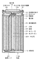
- FIG. 1 is a cross-sectional view illustrating a configuration example of the nonaqueous electrolyte secondary battery according to the first embodiment of the present technology.
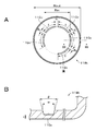
- FIG. 2A is a plan view showing an example of a can bottom having two or more grooves.
- 2B is a cross-sectional view taken along the line IIB-IIB in FIG. 2A.
- FIG. 3A is a plan view showing an example of a can bottom having two grooves of the same length.
- FIG. 3B is a plan view showing an example of a can bottom having three grooves of the same length.
- FIG. 4A is a plan view showing an example of a can bottom having four grooves of the same length.
- FIG. 4B is a plan view showing an example of a can bottom having five grooves of the same length.
- FIG. 5A is a plan view showing an example of a can bottom having grooves having different lengths.
- FIG. 5B is a plan view showing an example of a can bottom having different groove intervals.
- FIG. 6 is a schematic diagram for explaining the flow of heat when abnormal heat is applied to the battery.
- FIG. 7A is a plan view showing an example of a can bottom having an annular groove.
- FIG. 7B is a plan view showing an example of a can bottom having a C-shaped groove.
- FIG. 8 is an enlarged cross-sectional view showing a part of the spirally wound electrode body shown in FIG. FIG.
- FIG. 10A is a cross-sectional view illustrating a configuration example of a can bottom of a nonaqueous electrolyte secondary battery according to Modification 1 of the first embodiment of the present technology.
- FIG. 10B is a cross-sectional view illustrating a configuration example of a can bottom of the nonaqueous electrolyte secondary battery according to Modification 2 of the first embodiment of the present technology.
- It is a block diagram showing an example of 1 composition of a battery pack and electronic equipment concerning a 2nd embodiment of this art.
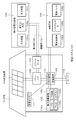
- It is a schematic diagram showing an example of 1 composition of an electrical storage system concerning a 3rd embodiment of this art.
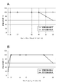
- FIG. 14A is a graph showing the percentage Ra of the inner diameter R in the groove to the outer diameter R out of the can bottom, the relationship between the pass rates.
- FIG. 14B is a graph showing the relationship between the ratio Rb of the total value D of the groove interval to the circumferential length L of the circumference and the test pass rate.
- FIG. 15A is a graph showing the relationship between the thickness t of the bottom of the can at the groove bottom and the test pass rate.
- FIG. 15B is a graph showing the relationship between the groove width w and the test pass rate.
- Embodiments of the present technology will be described in the following order. 1. First embodiment (example of cylindrical battery) 2 Second embodiment (example of battery pack and electronic device) 3 Third Embodiment (Example of Power Storage System) 4 Fourth Embodiment (Example of Electric Vehicle)
- Non-aqueous electrolyte secondary battery (hereinafter sometimes simply referred to as “battery”) according to the first embodiment of the present technology will be described with reference to FIG. 1.
- This nonaqueous electrolyte secondary battery is, for example, a so-called lithium ion secondary battery in which the capacity of the negative electrode is represented by a capacity component due to insertion and extraction of lithium (Li) as an electrode reactant.
- This non-aqueous electrolyte secondary battery is called a so-called cylindrical type, and a pair of strip-like positive electrode 21 and strip-like negative electrode 22 are laminated and wound inside a substantially hollow cylindrical battery can 11 via a separator 23.
- the wound electrode body 20 is rotated.
- the battery can 11 is made of iron (Fe) plated with nickel (Ni), and has one end closed and the other end open. Inside the battery can 11, an electrolytic solution as an electrolyte is injected and impregnated in the positive electrode 21, the negative electrode 22, and the separator 23.
- a pair of insulating plates 12 and 13 are respectively disposed perpendicular to the winding peripheral surface so as to sandwich the winding electrode body 20.
- the closed end side of the battery can 11 is referred to as “bottom side”
- the opposite side, that is, the open end side of the battery can 11 is referred to as “top side”.
- a battery lid 14 At the open end of the battery can 11, a battery lid 14, a safety valve mechanism 15 provided inside the battery lid 14, and a thermal resistance element (Positive16Temperature ⁇ Coefficient; PTC element) 16 are provided via a sealing gasket 17. It is attached by caulking. Thereby, the inside of the battery can 11 is sealed.
- the battery lid 14 is made of, for example, the same material as the battery can 11.
- the safety valve mechanism 15 discharges gas from the top side of the battery by cleaving or the like when gas is generated in the battery can 11 at the time of abnormality.
- the safety valve mechanism 15 is electrically connected to the battery lid 14, and when the internal pressure of the battery exceeds a certain level due to an internal short circuit or external heating, the disk plate 15 ⁇ / b> A is inverted and the battery lid 14 is reversed. And the wound electrode body 20 are disconnected from each other.
- the sealing gasket 17 is made of, for example, an insulating material, and the surface is coated with asphalt.
- the wound electrode body 20 has a substantially cylindrical shape.
- the wound electrode body 20 has a center hole 20H penetrating from the center of one end surface toward the center of the other end surface.
- a center pin 24 is inserted into the center hole 20H.
- the center pin 24 has a cylindrical shape with both ends open. For this reason, the center pin 24 functions as a flow path that guides the gas from the bottom side to the top side when the gas is generated in the battery can 11.
- a positive electrode lead 25 made of aluminum (Al) or the like is connected to the positive electrode 21 of the spirally wound electrode body 20, and a negative electrode lead 26 made of nickel or the like is connected to the negative electrode 22.
- the positive electrode lead 25 is electrically connected to the battery lid 14 by being welded to the safety valve mechanism 15, and the negative electrode lead 26 is welded to and electrically connected to the battery can 11.
- the open circuit voltage (that is, the battery voltage) in the fully charged state per pair of the positive electrode 21 and the negative electrode 22 may be 4.2 V or less, but from 4.2 V May be designed to be within a range of 4.4V to 6.0V, more preferably 4.4V to 5.0V.
- 4.2 V May be designed to be within a range of 4.4V to 6.0V, more preferably 4.4V to 5.0V.
- the battery can 11 the positive electrode 21, the negative electrode 22, the separator 23, and the electrolytic solution constituting the nonaqueous electrolyte secondary battery will be sequentially described.
- the battery can 11 has a can bottom 11Bt as a bottom on the side of the closed one end.
- the can bottom 11Bt has a circular shape as shown in FIG. 2A.
- the inner surface of the battery can 11 (hereinafter simply referred to as “the inner surface of the can bottom 11Bt”) has two or more grooves 11Gv identical to each other as shown in FIGS. 2A and 2B. It has on the circumference of. This circle has a concentric relationship with the outer shape of the can bottom 11Bt.
- the groove 11Gv has an arc shape.
- the number of the grooves 11Gv is not particularly limited as long as it is two or more. For example, as shown in FIGS. 3A, 3B, 4A, and 4B (hereinafter referred to as “FIG. 3A”, etc.) 5 or less is mentioned above.
- each groove 11Gv in the circumferential direction may be the same, and the interval d between the grooves 11Gv in the circumferential direction may be the same. That is, the two or more grooves 11Gv may have rotational symmetry with respect to the center of the can bottom 11Bt.
- the interval between the grooves 11Gv in the circumferential direction means the interval between the grooves 11Gv measured along the circumference where the groove 11Gv is provided.
- each groove 11Gv in the circumferential direction may be different, and the interval d between the grooves 11Gv in the circumferential direction may be the same.
- the length l of each groove 11Gv in the circumferential direction may be the same, and the interval d between the grooves 11Gv in the circumferential direction may be different, or (c) in the circumferential direction.
- the length l of each groove 11Gv may be different, and the interval d between the grooves 11Gv in the circumferential direction may be different.
- two or more grooves 11Gv may have non-rotational symmetry with respect to the center of the can bottom 11Bt.
- the battery may burst when abnormal heat is applied to the battery. If the ratio Rb exceeds 24%, the battery may burst when abnormal heat is applied to the battery. On the other hand, when the ratio Rb is less than 2%, the wound electrode body 20 may come out of the battery can 11 when abnormal heat is applied to the battery. Moreover, when the ratio Rb is less than 2% and the ratio Ra is 88% or more, the wound electrode body 20 may be taken out of the battery can 11 when the battery is dropped.
- the ratio Ra is set to 44% or more.
- heat flame
- the heat (flame) has an action of softening the groove 11Gv of the can bottom 11Bt, and the softer the groove 11Gv is closer to the outer peripheral portion of the wound electrode body 20, the easier it is.
- the ratio Ra is 44% or more, the groove 11Gv is close to the outer peripheral portion of the wound electrode body 20, and therefore when the abnormal heat is applied to the battery from the outside, the groove 11Gv of the can bottom 11Bt is easily softened.
- the groove 11Gv of the can bottom 11Bt is cleaved by the gas pressure increase of the can bottom 11Bt by the generated gas, and the gas can be released to the outside.
- the ratio Ra is less than 44%
- the groove 11Gv is far from the outer peripheral portion of the spirally wound electrode body 20, and thus the groove 11Gv is difficult to soften due to heat generation during the combustion test. Therefore, even if the gas pressure of the can bottom 11Bt is increased by the generated gas, the can bottom 11Bt may not be cleaved and the gas may not be released to the outside.
- the safety is lowered.
- the cleavage strength of the groove 11Gv is low, When the abnormal heat is applied or when the battery is dropped, the wound electrode body 20 may come out of the battery can 11. As shown in FIG. 7A, when the number of the grooves 11Gv is one and the groove 11Gv is an annular shape having no intermittent portion, the cleavage strength of the groove 11Gv is low, When the abnormal heat is applied or when the battery is dropped, the wound electrode body 20 may come out of the battery can 11. As shown in FIG.
- the ratio Rb is set to 2 In order to make the ratio between 24% and 24%, it is necessary to make the length of the circumferential groove 11Gv longer than a half circumference. However, with such a length, as in the case where the groove 11Gv has an annular shape, the cleavage strength of the groove 11Gv is lowered, and when abnormal heat is applied to the battery, When dropped, the wound electrode body 20 may come out of the battery can 11.
- the thickness t of the can bottom 11Bt at the bottom of the groove 11Gv is preferably 0.020 mm or more and 0.150 mm or less. If the thickness t is less than 0.020 mm, the wound electrode body 20 may come out of the battery can 11 when the battery is dropped. If the thickness t exceeds 0.150 mm, the battery may burst when abnormal heat is applied to the battery.
- the width w of the groove 11Gv is preferably 0.10 mm or more and 1.00 mm or less. If the width w is less than 0.10 mm, the battery may burst when abnormal heat is applied to the battery. If the width w exceeds 1.00 mm, the wound electrode body 20 may come out of the battery can 11 when the battery is dropped.
- the opening angle ⁇ of the groove 11Gv is, for example, not less than 0 degrees and not more than 90 degrees.
- the gas release pressure (cleavage pressure) of the groove 11Gv is preferably higher than the gas release pressure (working pressure) of the safety valve mechanism 15.
- the groove 11Gv of the can bottom 11Bt is intended to release gas to the outside of the battery when abnormal heat is applied to the battery, so that it is necessary to prevent the groove 11Gv from being cleaved during normal use. It is.
- the gas release pressure of the groove 11Gv is preferably lower than the battery internal pressure at which the sealing portion of the battery is destroyed. This is because when abnormal heat is applied to the battery, the groove 11Gv can be cleaved before the battery bursts, and the gas can be discharged to the outside of the battery.
- the gas release pressure of the groove 11Gv is preferably in the range of 20 kgf / cm 2 or more and 100 kgf / cm 2 or less.
- the cross-sectional shape of the groove 11Gv is, for example, a substantially polygonal shape, a substantially partial circular shape, a substantially partial elliptical shape, or an indefinite shape, but is not limited thereto.
- the curvature R etc. may be provided to the top of the polygonal shape.
- the polygonal shape include a triangular shape, a quadrangular shape such as a trapezoidal shape and a rectangular shape, and a pentagonal shape.
- the “partial circular shape” is a partial shape of a circular shape, for example, a semicircular shape.
- the partial elliptical shape is a partial shape of an elliptical shape, for example, a semi-elliptical shape.
- the bottom surface may be, for example, a flat surface, an uneven surface having a step, a curved surface having undulations, or a composite surface in which two or more of these surfaces are combined.
- the positive electrode 21 has, for example, a structure in which a positive electrode active material layer 21B is provided on both surfaces of a positive electrode current collector 21A. Although not shown, the positive electrode active material layer 21B may be provided only on one surface of the positive electrode current collector 21A.
- the positive electrode current collector 21A is made of, for example, a metal foil such as an aluminum foil, a nickel foil, or a stainless steel foil.
- the positive electrode active material layer 21B includes, for example, a positive electrode active material capable of inserting and extracting lithium (Li) that is an electrode reactant.
- the positive electrode active material layer 21B may further contain an additive as necessary. As the additive, for example, at least one of a conductive agent and a binder can be used.
- lithium-containing compounds such as lithium oxide, lithium phosphorus oxide, lithium sulfide, or an intercalation compound containing lithium are suitable, and two or more of these may be used in combination.
- a lithium-containing compound containing lithium, a transition metal element, and oxygen (O) is preferable.
- examples of such a lithium-containing compound include a lithium composite oxide having a layered rock salt structure shown in Formula (A) and a lithium composite phosphate having an olivine structure shown in Formula (B). Can be mentioned.
- the lithium-containing compound includes at least one member selected from the group consisting of cobalt (Co), nickel (Ni), manganese (Mn), and iron (Fe) as a transition metal element.
- a lithium-containing compound include a lithium composite oxide having a layered rock salt type structure represented by the formula (C), formula (D), or formula (E), and a spinel type compound represented by the formula (F).
- LiNi 0.50 Co 0.20 Mn 0.30 O 2 Li a CoO 2 (A ⁇ 1), Li b NiO 2 (b ⁇ 1), Li c1 Ni c2 Co 1-c2 O 2 (c1 ⁇ 1, 0 ⁇ c2 ⁇ 1), Li d Mn 2 O 4 (d ⁇ 1) or Li e FePO 4 (e ⁇ 1).
- M1 represents at least one element selected from Group 2 to Group 15 excluding nickel (Ni) and manganese (Mn).
- X represents Group 16 other than oxygen (O)) It represents at least one of elements and elements of group 17.
- p, q, y, and z are 0 ⁇ p ⁇ 1.5, 0 ⁇ q ⁇ 1.0, 0 ⁇ r ⁇ 1.0, ⁇ 0.10 ⁇ y ⁇ 0.20 and 0 ⁇ z ⁇ 0.2.
- M2 represents at least one element selected from Group 2 to Group 15.
- a and b are 0 ⁇ a ⁇ 2.0 and 0.5 ⁇ b ⁇ 2.0. It is a value within the range.
- M3 is cobalt (Co), magnesium (Mg), aluminum (Al), boron (B), titanium (Ti), vanadium (V), chromium (Cr), iron (Fe ), Copper (Cu), zinc (Zn), zirconium (Zr), molybdenum (Mo), tin (Sn), calcium (Ca), strontium (Sr) and tungsten (W) F
- g, h, j and k are 0.8 ⁇ f ⁇ 1.2, 0 ⁇ g ⁇ 0.5, 0 ⁇ h ⁇ 0.5, g + h ⁇ 1, ⁇ 0.1 ⁇ j. ⁇ 0.2, 0 ⁇ k ⁇ 0.1
- the composition of lithium varies depending on the state of charge and discharge, and the value of f represents the value in the complete discharge state.
- M4 is cobalt (Co), manganese (Mn), magnesium (Mg), aluminum (Al), boron (B), titanium (Ti), vanadium (V), chromium (Cr ), Iron (Fe), copper (Cu), zinc (Zn), molybdenum (Mo), tin (Sn), calcium (Ca), strontium (Sr), and tungsten (W).
- M, n, p and q are 0.8 ⁇ m ⁇ 1.2, 0.005 ⁇ n ⁇ 0.5, ⁇ 0.1 ⁇ p ⁇ 0.2, 0 ⁇ q ⁇ 0.1.
- M5 is nickel (Ni), manganese (Mn), magnesium (Mg), aluminum (Al), boron (B), titanium (Ti), vanadium (V), chromium (Cr ), Iron (Fe), copper (Cu), zinc (Zn), molybdenum (Mo), tin (Sn), calcium (Ca), strontium (Sr), and tungsten (W).
- R, s, t, and u are in a range of 0.8 ⁇ r ⁇ 1.2, 0 ⁇ s ⁇ 0.5, ⁇ 0.1 ⁇ t ⁇ 0.2, and 0 ⁇ u ⁇ 0.1. (Note that the composition of lithium varies depending on the state of charge and discharge, and the value of r represents a value in a fully discharged state.)
- M6 is cobalt (Co), nickel (Ni), magnesium (Mg), aluminum (Al), boron (B), titanium (Ti), vanadium (V), chromium (Cr ), Iron (Fe), copper (Cu), zinc (Zn), molybdenum (Mo), tin (Sn), calcium (Ca), strontium (Sr), and tungsten (W).
- V, w, x, and y are in the range of 0.9 ⁇ v ⁇ 1.1, 0 ⁇ w ⁇ 0.6, 3.7 ⁇ x ⁇ 4.1, and 0 ⁇ y ⁇ 0.1. (Note that the composition of lithium varies depending on the state of charge and discharge, and the value of v represents the value in a fully discharged state.)
- Li z M7PO 4 (However, in formula (G), M7 is cobalt (Co), manganese (Mn), iron (Fe), nickel (Ni), magnesium (Mg), aluminum (Al), boron (B), titanium (Ti ), Vanadium (V), niobium (Nb), copper (Cu), zinc (Zn), molybdenum (Mo), calcium (Ca), strontium (Sr), tungsten (W) and zirconium (Zr) Z represents a value in a range of 0.9 ⁇ z ⁇ 1.1, wherein the composition of lithium varies depending on the state of charge and discharge, and the value of z is a value in a fully discharged state. Represents.)
- the lithium-containing compound containing nickel (Ni) those having a Ni content of 80% or more are preferable. This is because a high battery capacity can be obtained when the Ni content is 80% or more.
- the battery capacity increases as described above, but the gas generation amount (oxygen release amount) of the positive electrode 21 is very large when abnormal heat is applied. Become.
- the nonaqueous electrolyte secondary battery according to the first embodiment particularly excellent safety improvement effects are exhibited when such an electrode with a large amount of gas generation is used.
- the lithium-containing compound having a Ni content of 80% or more is preferably a positive electrode material represented by the formula (H).
- Li v Ni w M8 x M9 y O z (H) (Where 0 ⁇ v ⁇ 2, w + x + y ⁇ 1, 0.8 ⁇ w ⁇ 1, 0 ⁇ x ⁇ 0.2, 0 ⁇ y ⁇ 0.2, 0 ⁇ z ⁇ 3, and M8 and M9 are , Co (cobalt), Fe (iron), Mn (manganese), Cu (copper), Zn (zinc), Al (aluminum), Cr (chromium), V (vanadium), Ti (titanium), Mg (magnesium) , At least one selected from Zr (zirconium).)
- positive electrode materials capable of inserting and extracting lithium include inorganic compounds not containing lithium, such as MnO 2 , V 2 O 5 , V 6 O 13 , NiS, and MoS.
- the positive electrode material capable of inserting and extracting lithium may be other than the above.
- the positive electrode material illustrated above may be mixed 2 or more types by arbitrary combinations.
- binder examples include resin materials such as polyvinylidene fluoride (PVdF), polytetrafluoroethylene (PTFE), polyacrylonitrile (PAN), styrene butadiene rubber (SBR), and carboxymethyl cellulose (CMC), and these resin materials. At least one selected from copolymers and the like mainly composed of is used.
- PVdF polyvinylidene fluoride
- PTFE polytetrafluoroethylene
- PAN polyacrylonitrile
- SBR styrene butadiene rubber
- CMC carboxymethyl cellulose
- the conductive agent examples include carbon materials such as graphite, carbon black, and ketjen black, and one or more of them are used in combination.
- a metal material or a conductive polymer material may be used as long as it is a conductive material.
- the negative electrode 22 has, for example, a structure in which a negative electrode active material layer 22B is provided on both surfaces of a negative electrode current collector 22A. Although not shown, the negative electrode active material layer 22B may be provided only on one surface of the negative electrode current collector 22A.
- the negative electrode current collector 22A is made of, for example, a metal foil such as a copper foil, a nickel foil, or a stainless steel foil.
- the negative electrode active material layer 22B contains one or more negative electrode active materials capable of inserting and extracting lithium as a negative electrode active material.
- the negative electrode active material layer 22B may further contain an additive such as a binder as necessary.
- the electrochemical equivalent of the negative electrode material capable of occluding and releasing lithium is larger than the electrochemical equivalent of the positive electrode 21, In the middle, lithium metal does not deposit on the negative electrode 22.
- Examples of the negative electrode material capable of occluding and releasing lithium include materials capable of occluding and releasing lithium and containing at least one of a metal element and a metalloid element as a constituent element.
- the negative electrode 22 containing such a negative electrode material is referred to as an alloy-based negative electrode. This is because a high energy density can be obtained by using such a material. In particular, the use with a carbon material is more preferable because a high energy density can be obtained and excellent cycle characteristics can be obtained.
- the negative electrode material may be a single element, alloy or compound of a metal element or metalloid element, or may have at least a part of one or more of these phases.
- the alloy includes an alloy including one or more metal elements and one or more metalloid elements in addition to an alloy composed of two or more metal elements.
- the nonmetallic element may be included.
- Some of the structures include a solid solution, a eutectic (eutectic mixture), an intermetallic compound, or two or more of them.
- metal elements or metalloid elements constituting the negative electrode material examples include magnesium (Mg), boron (B), aluminum (Al), gallium (Ga), indium (In), silicon (Si), and germanium (Ge). ), Tin (Sn), lead (Pb), bismuth (Bi), cadmium (Cd), silver (Ag), zinc (Zn), hafnium (Hf), zirconium (Zr), yttrium (Y), palladium (Pd) ) Or platinum (Pt). These may be crystalline or amorphous.
- the negative electrode material a material containing a 4B group metal element or a semimetal element in the short-period type periodic table as a constituent element is preferable, and at least one of silicon (Si) and tin (Sn) is particularly preferable. It is included as an element. This is because silicon (Si) and tin (Sn) have a large ability to occlude and release lithium (Li), and a high energy density can be obtained.
- tin (Sn) As an alloy of tin (Sn), for example, as a second constituent element other than tin (Sn), silicon (Si), nickel (Ni), copper (Cu), iron (Fe), cobalt (Co), manganese (Mn), zinc (Zn), indium (In), silver (Ag), titanium (Ti), germanium (Ge), bismuth (Bi), antimony (Sb), and chromium (Cr) The thing containing at least 1 sort is mentioned.
- Si As an alloy of silicon (Si), for example, as a second constituent element other than silicon (Si), tin (Sn), nickel (Ni), copper (Cu), iron (Fe), cobalt (Co), manganese (Mn), zinc (Zn), indium (In), silver (Ag), titanium (Ti), germanium (Ge), bismuth (Bi), antimony (Sb), and chromium (Cr).
- Si silicon
- Si tin
- Ni nickel
- Cu copper
- iron (Fe) cobalt
- Mn manganese
- Zn zinc
- indium (In) silver (Ag), titanium (Ti), germanium (Ge), bismuth (Bi), antimony (Sb), and chromium (Cr).
- Cr chromium
- tin (Sn) compound or silicon (Si) compound examples include those containing oxygen (O) or carbon (C). In addition to tin (Sn) or silicon (Si), the above-described compounds are used. Two constituent elements may be included. Specific examples of the tin (Sn) compound include silicon oxide represented by SiO v (0.2 ⁇ v ⁇ 1.4).
- Examples of the negative electrode material capable of inserting and extracting lithium include non-graphitizable carbon, graphitizable carbon, graphite, pyrolytic carbons, cokes, glassy carbons, and fired organic polymer compounds And carbon materials such as carbon fiber or activated carbon.
- graphite it is preferable to use spheroidized natural graphite or substantially spherical artificial graphite.
- artificial graphite artificial graphite obtained by graphitizing mesocarbon microbeads (MCMB) or artificial graphite obtained by graphitizing and pulverizing a coke raw material is preferable.
- Examples of the coke include pitch coke, needle coke, and petroleum coke.
- An organic polymer compound fired body refers to a carbonized material obtained by firing a polymer material such as phenol resin or furan resin at an appropriate temperature, and part of it is non-graphitizable carbon or graphitizable carbon.
- graphite is preferable because it has a high electrochemical equivalent and can provide a high energy density.
- non-graphitizable carbon is preferable because excellent characteristics can be obtained.
- those having a low charge / discharge potential specifically, those having a charge / discharge potential close to that of lithium metal are preferable because a high energy density of the battery can be easily realized.
- Examples of the negative electrode material capable of inserting and extracting lithium further include other metal compounds or polymer materials.
- Examples of other metal compounds include oxides such as MnO 2 , V 2 O 5 , and V 6 O 13 , sulfides such as NiS and MoS, and lithium nitrides such as LiN 3 , and polymer materials include polyacetylene. , Polyaniline or polypyrrole.
- binder examples include resin materials such as polyvinylidene fluoride (PVdF), polytetrafluoroethylene (PTFE), polyacrylonitrile (PAN), styrene butadiene rubber (SBR), and carboxymethyl cellulose (CMC), and these resin materials. At least one selected from copolymers and the like mainly composed of is used.
- PVdF polyvinylidene fluoride
- PTFE polytetrafluoroethylene
- PAN polyacrylonitrile
- SBR styrene butadiene rubber
- CMC carboxymethyl cellulose
- the separator 23 separates the positive electrode 21 and the negative electrode 22 and allows lithium ions to pass through while preventing a short circuit of current due to contact between the two electrodes.
- the separator 23 is made of, for example, a porous film made of synthetic resin made of polytetrafluoroethylene, polypropylene, polyethylene, or the like, or a porous film made of ceramic, and these two or more kinds of porous films are laminated. It may be a structure. Among these, a porous film made of polyolefin is preferable because it is excellent in the effect of preventing short circuit and can improve the safety of the battery due to the shutdown effect.
- polyethylene is preferable as a material constituting the separator 23 because it can obtain a shutdown effect within a range of 100 ° C. or higher and 160 ° C. or lower and is excellent in electrochemical stability.
- Polypropylene is also preferable.
- any resin having chemical stability can be used by copolymerizing or blending with polyethylene or polypropylene.
- the separator 23 is impregnated with an electrolytic solution that is a liquid electrolyte.
- the electrolytic solution contains a solvent and an electrolyte salt dissolved in the solvent.
- the electrolytic solution may contain a known additive in order to improve battery characteristics.
- cyclic carbonates such as ethylene carbonate or propylene carbonate can be used, and it is preferable to use one of ethylene carbonate and propylene carbonate, particularly a mixture of both. This is because the cycle characteristics can be improved.
- the solvent in addition to these cyclic carbonates, it is preferable to use a mixture of chain carbonates such as diethyl carbonate, dimethyl carbonate, ethylmethyl carbonate or methylpropyl carbonate. This is because high ionic conductivity can be obtained.
- the solvent preferably further contains 2,4-difluoroanisole or vinylene carbonate. This is because 2,4-difluoroanisole can improve discharge capacity, and vinylene carbonate can improve cycle characteristics. Therefore, it is preferable to use a mixture of these because the discharge capacity and cycle characteristics can be improved.
- examples of the solvent include butylene carbonate, ⁇ -butyrolactone, ⁇ -valerolactone, 1,2-dimethoxyethane, tetrahydrofuran, 2-methyltetrahydrofuran, 1,3-dioxolane, 4-methyl-1,3- Dioxolane, methyl acetate, methyl propionate, acetonitrile, glutaronitrile, adiponitrile, methoxyacetonitrile, 3-methoxypropironitrile, N, N-dimethylformamide, N-methylpyrrolidinone, N-methyloxazolidinone, N, N-dimethyl Examples include imidazolidinone, nitromethane, nitroethane, sulfolane, dimethyl sulfoxide, and trimethyl phosphate.
- a compound obtained by substituting at least a part of hydrogen in these non-aqueous solvents with fluorine may be preferable because the reversibility of the electrode reaction may be improved depending on the type of electrode to be combined.
- lithium salt As electrolyte salt, lithium salt is mentioned, for example, 1 type may be used independently, and 2 or more types may be mixed and used for it.
- Lithium salts include LiPF 6 , LiBF 4 , LiAsF 6 , LiClO 4 , LiB (C 6 H 5 ) 4 , LiCH 3 SO 3 , LiCF 3 SO 3 , LiN (SO 2 CF 3 ) 2 , LiC (SO 2 CF 3 ) 3 , LiAlCl 4 , LiSiF 6 , LiCl, difluoro [oxolato-O, O ′] lithium borate, lithium bisoxalate borate, or LiBr.
- LiPF 6 is preferable because it can obtain high ion conductivity and can improve cycle characteristics.
- lithium ions when charged, for example, lithium ions are released from the positive electrode active material layer 21B and inserted into the negative electrode active material layer 22B through the electrolytic solution.
- lithium ions when discharging is performed, for example, lithium ions are released from the negative electrode active material layer 22B and inserted into the positive electrode active material layer 21B through the electrolytic solution.
- the gas pressure on the bottom side of the battery is rarely increased abnormally.
- the amount of generated gas is large and the center hole 20H of the wound electrode body 20 does not have a sufficient size, the amount of gas flowing to the bottom side increases and the gas flowing to the bottom side is centered. Since it becomes difficult to smoothly wrap around the top side through the hole 20H, the gas pressure on the bottom side of the battery tends to increase abnormally. In particular, in a high-capacity, high-power nonaqueous electrolyte secondary battery, the gas pressure tends to increase abnormally on the bottom side of the battery.
- the gas accumulated in the can bottom 11Bt can be discharged by appropriately cleaving the groove 11Gv in response to an abnormal increase in the gas pressure on the bottom side.
- the wound electrode body 20 does not jump out of the can bottom 11Bt, and only the gas accumulated in the can bottom 11Bt can be released from the can bottom 11Bt.
- a first positive electrode active material, a second positive electrode active material, a conductive agent, and a binder are mixed to prepare a positive electrode mixture, and this positive electrode mixture is mixed with N-methyl-2-
- a paste-like positive electrode mixture slurry is prepared by dispersing in a solvent such as pyrrolidone (NMP).
- NMP pyrrolidone
- this positive electrode mixture slurry is applied to the positive electrode current collector 21 ⁇ / b> A, the solvent is dried, and the positive electrode active material layer 21 ⁇ / b> B is formed by compression molding with a roll press or the like, thereby forming the positive electrode 21.
- a negative electrode active material and a binder are mixed to prepare a negative electrode mixture, and this negative electrode mixture is dispersed in a solvent such as N-methyl-2-pyrrolidone to obtain a paste-like negative electrode mixture slurry Is made.
- the negative electrode mixture slurry is applied to the negative electrode current collector 22A, the solvent is dried, and the negative electrode active material layer 22B is formed by compression molding using a roll press or the like, and the negative electrode 22 is manufactured.
- the positive electrode lead 25 is attached to the positive electrode current collector 21A by welding or the like, and the negative electrode lead 26 is attached to the negative electrode current collector 22A by welding or the like.
- the positive electrode 21 and the negative electrode 22 are wound through the separator 23.
- the front end of the positive electrode lead 25 is welded to the safety valve mechanism 15, and the front end of the negative electrode lead 26 is welded to the battery can 11, and the wound positive electrode 21 and negative electrode 22 are connected with the pair of insulating plates 12 and 13. It is housed inside the sandwiched battery can 11.
- the electrolytic solution is injected into the battery can 11 and impregnated in the separator 23.
- the battery lid 14, the safety valve mechanism 15, and the heat sensitive resistance element 16 are fixed to the opening end of the battery can 11 by caulking through a sealing gasket 17. Thereby, the secondary battery shown in FIG. 1 is obtained.
- the inner surface of the can bottom 11Bt has two or more grooves 11Gv on the same circumference.
- the can bottom 11Bt ratio Ra of the inner diameter R in groove 11Gv to the outer diameter R out is at least 44%, of the total D of the groove spacing 11Gv the circumferential length L of the circumference groove 11Gv is provided
- the ratio Rb is 2% or more and 24% or less.
- the center pin 24 has a cylindrical shape as described above, and functions as a flow path for guiding the generated gas from the bottom side to the top side of the battery when gas is generated. If the center pin 24 is present, the center hole 20H of the wound electrode body 20 can be prevented from being crushed, but the center pin 24 is crushed by the expansion of the wound electrode body 20, and the center hole 20H of the wound electrode body 20 is The gas pressure on the bottom side may increase abnormally because it is not sufficiently large. In particular, particularly in a high-capacity, high-power battery, since the expansion of the wound electrode body 20 is large during charging / discharging or when abnormal heat is applied, the center hole 20H of the wound electrode body 20 is sufficiently large. Therefore, the gas pressure on the bottom side tends to increase abnormally. Therefore, regardless of the presence or absence of the center pin 24, providing the two or more grooves Gv in the can bottom 11Bt as described above is effective for improving the safety of the battery.
- the surface that is the outside of the battery can 11 (hereinafter simply referred to as “the outer surface of the can bottom 11Bt”) has two or more grooves 11Gv in the same circumference as shown in FIG. 10A. You may have on. Further, both the inner side surface and the outer side surface of the can bottom 11Bt may have two or more grooves 11Gv on the same circumference as shown in FIG. 10B.
- FIG. 10B shows an example in which the grooves 11Gv provided on the inner side surface and the outer side surface are provided so as to overlap in the thickness direction of the can bottom 11Bt, but the grooves 11Gv provided on the inner side surface and the outer side surface are shown. However, they may be provided so as not to overlap in the thickness direction of the can bottom 11Bt but to be shifted in the in-plane direction of the can bottom 11Bt.
- the battery having the center pin 24 has been described, but a battery not having the center pin 24 may be used.
- the center hole 20H of the spirally wound electrode body 20 tends not to have a sufficient size due to the expansion of the spirally wound electrode body 20, so that the effect of improving safety by the groove 11Gv is remarkably exhibited.
- Second Embodiment> a battery pack and an electronic device including the nonaqueous electrolyte secondary battery according to the first embodiment will be described.
- the electronic device 400 includes an electronic circuit 401 of the electronic device body and a battery pack 300.
- the battery pack 300 is electrically connected to the electronic circuit 401 via the positive terminal 331a and the negative terminal 331b.
- the electronic device 400 has a configuration in which the battery pack 300 is detachable by a user.
- the configuration of the electronic device 400 is not limited to this, and the battery pack 300 is built in the electronic device 400 so that the user cannot remove the battery pack 300 from the electronic device 400. May be.
- the positive terminal 331a and the negative terminal 331b of the battery pack 300 are connected to the positive terminal and the negative terminal of a charger (not shown), respectively.
- the positive terminal 331a and the negative terminal 331b of the battery pack 300 are connected to the positive terminal and the negative terminal of the electronic circuit 401, respectively.
- the electronic device 400 for example, a notebook personal computer, a tablet computer, a mobile phone (for example, a smartphone), a portable information terminal (Personal Digital Assistant: PDA), a display device (LCD, EL display, electronic paper, etc.), imaging, etc.
- Devices eg digital still cameras, digital video cameras, etc.
- audio equipment eg portable audio players
- game machines cordless phones, e-books, electronic dictionaries, radio, headphones, navigation systems, memory cards, pacemakers, hearing aids, Electric tools, electric shavers, refrigerators, air conditioners, TVs, stereos, water heaters, microwave ovens, dishwashers, washing machines, dryers, lighting equipment, toys, medical equipment, robots, road conditioners, traffic lights Etc.
- the electronic circuit 401 includes, for example, a CPU, a peripheral logic unit, an interface unit, a storage unit, and the like, and controls the entire electronic device 400.
- the battery pack 300 includes an assembled battery 301 and a charge / discharge circuit 302.
- the assembled battery 301 is configured by connecting a plurality of secondary batteries 301a in series and / or in parallel.
- the plurality of secondary batteries 301a are connected, for example, in n parallel m series (n and m are positive integers).
- FIG. 11 shows an example in which six secondary batteries 301a are connected in two parallel three series (2P3S).
- the nonaqueous electrolyte secondary battery according to the first embodiment is used as the secondary battery 301a.
- the charging / discharging circuit 302 is a control unit that controls charging / discharging of the assembled battery 301. Specifically, during charging, the charging / discharging circuit 302 controls charging of the assembled battery 301. On the other hand, at the time of discharging (that is, when the electronic device 400 is used), the charging / discharging circuit 302 controls the discharging of the electronic device 400.
- the battery pack 300 includes the assembled battery 301 including a plurality of secondary batteries 301 a has been described as an example. However, the battery pack 300 is replaced with one assembled battery 301. You may employ
- a power storage system that includes the nonaqueous electrolyte secondary battery according to the first embodiment in a power storage device will be described.
- This power storage system may be anything as long as it uses power, and includes a simple power device.
- This power system includes, for example, a smart grid, a home energy management system (HEMS), a vehicle, and the like, and can also store electricity.
- HEMS home energy management system
- This power storage system 100 is a residential power storage system, from a centralized power system 102 such as a thermal power generation 102a, a nuclear power generation 102b, and a hydropower generation 102c through a power network 109, an information network 112, a smart meter 107, a power hub 108, etc. Electric power is supplied to the power storage device 103. At the same time, power is supplied to the power storage device 103 from an independent power source such as the home power generation device 104. The electric power supplied to the power storage device 103 is stored. Electric power used in the house 101 is fed using the power storage device 103. The same power storage system can be used not only for the house 101 but also for buildings.
- the house 101 is provided with a home power generation device 104, a power consumption device 105, a power storage device 103, a control device 110 that controls each device, a smart meter 107, a power hub 108, and a sensor 111 that acquires various information.
- Each device is connected by a power network 109 and an information network 112.
- a solar cell, a fuel cell, or the like is used as the home power generation device 104, and the generated power is supplied to the power consumption device 105 and / or the power storage device 103.
- the power consuming device 105 is a refrigerator 105a, an air conditioner 105b, a television receiver 105c, a bath 105d, or the like.
- the electric power consumption device 105 includes an electric vehicle 106.
- the electric vehicle 106 is an electric vehicle 106a, a hybrid car 106b, an electric motorcycle 106c, or the like.
- the power storage device 103 includes the nonaqueous electrolyte secondary battery according to the first embodiment.
- the smart meter 107 has a function of measuring the usage amount of commercial power and transmitting the measured usage amount to an electric power company.
- the power network 109 may be any one or a combination of DC power supply, AC power supply, and non-contact power supply.
- the various sensors 111 are, for example, human sensors, illuminance sensors, object detection sensors, power consumption sensors, vibration sensors, contact sensors, temperature sensors, infrared sensors, and the like. Information acquired by various sensors 111 is transmitted to the control device 110. Based on the information from the sensor 111, the weather state, the state of a person, and the like can be grasped, and the power consumption device 105 can be automatically controlled to minimize the energy consumption. Furthermore, the control device 110 can transmit information regarding the house 101 to an external power company or the like via the Internet.
- the power hub 108 performs processing such as branching of power lines and DC / AC conversion.
- the communication method of the information network 112 connected to the control device 110 includes a method using a communication interface such as UART (Universal Asynchronous Receiver-Transceiver), Bluetooth (registered trademark), ZigBee, Wi-Fi.
- a communication interface such as UART (Universal Asynchronous Receiver-Transceiver), Bluetooth (registered trademark), ZigBee, Wi-Fi.
- the Bluetooth (registered trademark) system is applied to multimedia communication and can perform one-to-many connection communication.
- ZigBee uses a physical layer of IEEE (Institute of Electrical and Electronics Electronics) 802.15.4. IEEE 802.15.4 is the name of a short-range wireless network standard called PAN (Personal Area Network) or W (Wireless) PAN.
- the control device 110 is connected to an external server 113.
- the server 113 may be managed by any one of the house 101, the power company, and the service provider.
- the information transmitted and received by the server 113 is, for example, information related to power consumption information, life pattern information, power charges, weather information, natural disaster information, and power transactions. These pieces of information may be transmitted / received from a power consuming device in the home (for example, a television receiver) or may be transmitted / received from a device outside the home (for example, a mobile phone). Such information may be displayed on a device having a display function, such as a television receiver, a mobile phone, or a PDA (Personal Digital Assistant).
- a display function such as a television receiver, a mobile phone, or a PDA (Personal Digital Assistant).
- the control device 110 that controls each unit includes a CPU (Central Processing Unit), a RAM (Random Access Memory), a ROM (Read Only Memory), and the like, and is stored in the power storage device 103 in this example.
- the control device 110 is connected to the power storage device 103, the home power generation device 104, the power consumption device 105, the various sensors 111, the server 113 and the information network 112, and adjusts, for example, the amount of commercial power used and the amount of power generation. It has a function. In addition, you may provide the function etc. which carry out an electric power transaction in an electric power market.
- the power generated by the home power generation device 104 is supplied to the power storage device 103.
- the power generated by the home power generation device 104 can be stored. Therefore, even if the generated power of the home power generation device 104 fluctuates, it is possible to perform control such that the amount of power to be sent to the outside is constant or discharge is performed as necessary.
- the electric power obtained by solar power generation is stored in the power storage device 103, and midnight power with a low charge is stored in the power storage device 103 at night, and the power stored by the power storage device 103 is discharged during a high daytime charge. You can also use it.
- control device 110 is stored in the power storage device 103 .
- control device 110 may be stored in the smart meter 107 or may be configured independently.
- the power storage system 100 may be used for a plurality of homes in an apartment house, or may be used for a plurality of detached houses.
- the hybrid vehicle 200 is a hybrid vehicle that employs a series hybrid system.
- the series hybrid system is a vehicle that runs on the power driving force conversion device 203 using electric power generated by a generator that is driven by an engine or electric power that is temporarily stored in a battery.
- the hybrid vehicle 200 includes an engine 201, a generator 202, a power driving force conversion device 203, driving wheels 204a, driving wheels 204b, wheels 205a, wheels 205b, a battery 208, a vehicle control device 209, various sensors 210, and a charging port 211. Is installed.
- the battery 208 the nonaqueous electrolyte secondary battery according to the first embodiment is used.
- Hybrid vehicle 200 travels using electric power / driving force conversion device 203 as a power source.
- An example of the power driving force conversion device 203 is a motor.
- the electric power / driving force converter 203 is operated by the electric power of the battery 208, and the rotational force of the electric power / driving force converter 203 is transmitted to the driving wheels 204a and 204b.
- DC-AC DC-AC
- AC-DC conversion AC-DC conversion
- the power driving force converter 203 can be applied to either an AC motor or a DC motor.
- the various sensors 210 control the engine speed via the vehicle control device 209 and control the opening (throttle opening) of a throttle valve (not shown).
- the various sensors 210 include a speed sensor, an acceleration sensor, an engine speed sensor, and the like.
- the rotational force of the engine 201 is transmitted to the generator 202, and the electric power generated by the generator 202 by the rotational force can be stored in the battery 208.
- the resistance force at the time of deceleration is applied as a rotational force to the power driving force conversion device 203, and the regenerative electric power generated by the power driving force conversion device 203 by this rotational force is used as the battery 208. Accumulated in.
- the battery 208 is connected to an external power source of the hybrid vehicle 200 via the charging port 211, so that it is possible to receive power from the external power source using the charging port 211 as an input port and store the received power. is there.
- an information processing apparatus that performs information processing related to vehicle control based on information related to the nonaqueous electrolyte secondary battery may be provided.
- an information processing apparatus for example, there is an information processing apparatus that displays a battery remaining amount based on information on the remaining amount of a nonaqueous electrolyte secondary battery.
- the series hybrid vehicle that runs on the motor using the electric power generated by the generator that is driven by the engine or the electric power that is temporarily stored in the battery has been described as an example.
- the present technology is also effective for a parallel hybrid vehicle that uses both engine and motor outputs as drive sources and switches between the three modes of running with only the engine, running with only the motor, and running with the engine and motor. Applicable.
- the present technology can be effectively applied to a so-called electric vehicle that travels only by a drive motor without using an engine.
- a negative electrode was produced as follows. First, 97 parts by mass of artificial graphite powder as a negative electrode active material and 3 parts by mass of polyvinylidene fluoride as a binder were mixed to form a negative electrode mixture, which was then dispersed in N-methyl-2-pyrrolidone to obtain a paste. A negative electrode mixture slurry was obtained. Next, the negative electrode mixture slurry was applied to both sides of a negative electrode current collector made of a strip-shaped copper foil (15 ⁇ m thick), dried, and then compression molded with a roll press to form a negative electrode active material layer. . Next, a nickel negative electrode lead was attached to one end of the negative electrode current collector.
- the battery was assembled as follows. First, a positive electrode and a negative electrode obtained as described above are laminated in the order of a negative electrode, a separator, a positive electrode, and a separator through a separator made of a microporous polyethylene stretched film having a thickness of 23 ⁇ m, and wound many times. A jelly roll type wound electrode body was obtained.
- a battery can having an outer diameter of 18.20 mm having a can bottom having the following configuration was prepared.
- Groove shape Arc shape Number of grooves: 2 (same length)
- Groove arrangement equidistant arrangement (rotation symmetry with respect to the center of the bottom of the can)
- Can bottom outer diameter (diameter) R out 18.20 mm
- Groove inner diameter (diameter) R in 4 mm to 16 mm
- Circumference L of the circumference where the groove is formed 13 mm to 50 mm
- Groove width w 0.4 mm
- Groove opening angle 30 degrees
- a non-aqueous electrolyte was prepared by dissolving LiPF 6 as an electrolyte salt to a concentration of 1 mol / dm 3 in a solvent in which ethylene carbonate and methyl ethyl carbonate were mixed at a volume ratio of 1: 1.
- a cylindrical nonaqueous electrolyte secondary battery (hereinafter simply referred to as “battery”) having an outer diameter (diameter) of 18.20 mm and a height of 65 mm was produced.
- This battery is designed so that the amount of the positive electrode active material and the amount of the negative electrode active material are adjusted so that the open circuit voltage (that is, the battery voltage) at the time of full charge is 4.2 V, which will be described later.
- the evaluation was performed at 4.4 V (overcharged state exceeding the normal use range voltage).
- Table 1 shows the test results of the batteries of Examples 1-1 to 4-4 and Comparative Examples 1-1 to 6-6.
- test results of the batteries of Examples 1-1 to 1-4 and Comparative Examples 1-1 and 1-2 are representatively shown in FIG. 14A. Further, the test results of the batteries of Examples 1-1, 2-1, 3-1, 4-1 and Comparative Examples 5-5 and 6-5 are representatively shown in FIG. 14B.
- ratio Ra is less than 44%. This is because the groove is too far away from the outer periphery of the wound electrode body and the groove is difficult to soften due to the heat generated during the combustion test, so it is difficult for the gas to escape from the bottom of the can without tearing the bottom of the can. It is because it becomes.
- the ratio Rb is less than 2%, the acceptance rate of the combustion test tends to decrease. This is because the gap between the grooves is small, so that the entire bottom of the can is cleaved during the combustion test, and the contents of the battery pop out.
- the ratio Rb is less than 2% and the ratio Ra is 88% or more, the passing rate of the drop test tends to decrease. This is because the gap between the grooves is small and the inner diameter of the groove is large, so that the cleavage strength of the groove is too low, the groove is cleaved during the drop test, and the contents of the battery pop out.
- the ratio Rb exceeds 24%, the acceptance rate of the combustion test tends to decrease. This is because the joints are large and the cleaving strength of the grooves is high, so that the can bottom does not cleave during the combustion test, and the battery ruptures.
- the ratio Ra is 44% or more and the ratio Rb is 2% or more and 24% or less.
- Example 6-1 ⁇ Ii Sample in which the thickness t of the can bottom at the groove bottom or the width w of the groove is changed> (Examples 6-1 to 6-6) As shown in Table 2, a battery was obtained in the same manner as in Example 1-1 except that the thickness t of the can bottom at the bottom of the groove was changed in the range of 0.010 mm to 0.200 mm.
- Examples 7-1 to 7-7) As shown in Table 3, a battery was obtained in the same manner as in Example 1-1 except that the groove width w was changed in the range of 0.05 mm to 2.00 mm.
- Table 2 shows the test results of Examples 1-1 and 6-1 to 6-6.
- Table 3 shows the test results of Examples 1-1 and 7-1 to 7-7.
- FIG. 15A shows the test results of the batteries of Examples 1-1 and 6-1 to 6-6. Further, the test results of the batteries of Examples 1-1 and 7-1 to 7-7 are shown in FIG. 15B.
- the acceptance rate of the combustion test tends to decrease. This is because the groove splitting strength (that is, the gas splitting pressure of the groove) becomes too high, and the battery side surface and the sealing part are first ruptured before the groove is opened, and the contents are ejected therefrom.
- the width w of the groove 11Gv exceeds 1.00 mm, there is a tendency that the pass rate of the drop test is lowered. This is because the cleaving strength of the groove becomes too low, so that the groove is cleaved during the drop test and the contents of the battery pop out.
- the thickness t of the can bottom at the bottom of the groove is 0.020 mm or more and 0.150 mm or less, and the width w of the groove is 0. It is 10 mm or more and 1.00 mm or less.
- the present technology is applied to the lithium ion secondary battery.
- the present technology can also be applied to a secondary battery other than the lithium ion secondary battery and a primary battery. It is.
- the present technology is particularly effective when applied to a lithium ion secondary battery.
- the present technology can also employ the following configurations.
- the thickness of the bottom at the groove bottom is 0.020 mm or more and 0.150 mm or less, The battery according to (1), wherein the groove has a width of 0.10 mm or more and 1.00 mm or less.
- the electrode body includes a positive electrode and a negative electrode, The battery according to any one of (1) to (7), wherein an open circuit voltage in a fully charged state per pair of the positive electrode and the negative electrode is in a range of 4.4 V to 6.00 V. (9) The battery according to any one of (1) to (8), wherein the electrode body includes a positive electrode including a positive electrode active material having an average composition represented by the following formula (1).
- a battery pack comprising: a control unit that controls the battery.
Landscapes
- Engineering & Computer Science (AREA)
- Chemical & Material Sciences (AREA)
- General Chemical & Material Sciences (AREA)
- Chemical Kinetics & Catalysis (AREA)
- Electrochemistry (AREA)
- Power Engineering (AREA)
- Manufacturing & Machinery (AREA)
- Inorganic Chemistry (AREA)
- Life Sciences & Earth Sciences (AREA)
- Sustainable Development (AREA)
- Sustainable Energy (AREA)
- Transportation (AREA)
- Mechanical Engineering (AREA)
- Microelectronics & Electronic Packaging (AREA)
- Sealing Battery Cases Or Jackets (AREA)
- Gas Exhaust Devices For Batteries (AREA)
- Battery Electrode And Active Subsutance (AREA)
- Secondary Cells (AREA)
Abstract
Description
特許文献2には、金属ケースの底面に1つ以上の切裂開放する部分を周壁に沿って円弧状で、かつ断面がV字状溝の形に設けることが記載されている。
特許文献3には、電池内に発生したガス圧力による電池ケース底面部の薄肉部の破断圧力が、防爆封口板の弁体の破断圧力よりも大きく、かつ電池封口部の耐圧より小さくなるようにすることが記載されている。
1.第1の実施形態(円筒型電池の例)
2 第2の実施形態(電池パックおよび電子機器の例)
3 第3の実施形態(蓄電システムの例)
4 第4の実施形態(電動車両の例)
[電池の構成]
以下、図1を参照しながら、本技術の第1の実施形態に係る非水電解質二次電池(以下単に「電池」ということがある。)の一構成例について説明する。この非水電解質二次電池は、例えば、負極の容量が、電極反応物質であるリチウム(Li)の吸蔵および放出による容量成分により表されるいわゆるリチウムイオン二次電池である。この非水電解質二次電池はいわゆる円筒型といわれるものであり、ほぼ中空円柱状の電池缶11の内部に、一対の帯状の正極21と帯状の負極22とがセパレータ23を介して積層し巻回された巻回電極体20を有している。電池缶11は、ニッケル(Ni)のめっきがされた鉄(Fe)により構成されており、一端部が閉鎖され他端部が開放されている。電池缶11の内部には、電解質としての電解液が注入され、正極21、負極22およびセパレータ23に含浸されている。また、巻回電極体20を挟むように巻回周面に対して垂直に一対の絶縁板12、13がそれぞれ配置されている。なお、以下の説明において、電池の両端部のうち、電池缶11の閉鎖端部側を「ボトム側」といい、それとは反対側、すなわち電池缶11の開放端部側を「トップ側」ということがある。
電池缶11は、閉鎖されている一端部の側に、底部としての缶底11Btを有している。この缶底11Btを垂直な方向から見ると、缶底11Btは、図2Aに示すように、円形を有している。缶底11Btの両面のうち、電池缶11の内側となる面(以下単に「缶底11Btの内側面」という。)は、図2A、図2Bに示すように、2つ以上の溝11Gvを同一の円周上に有している。この円は、缶底11Btの外形と同心円の関係にある。
正極21は、図8に示すように、例えば、正極集電体21Aの両面に正極活物質層21Bが設けられた構造を有している。なお、図示はしないが、正極集電体21Aの片面のみに正極活物質層21Bを設けるようにしてもよい。正極集電体21Aは、例えば、アルミニウム箔、ニッケル箔あるいはステンレス箔などの金属箔により構成されている。正極活物質層21Bは、例えば、電極反応物質であるリチウム(Li)を吸蔵および放出することが可能な正極活物質を含んでいる。正極活物質層21Bは、必要に応じて添加剤をさらに含んでいてもよい。添加剤としては、例えば、導電剤および結着剤のうちの少なくとも1種を用いることができる。
正極活物質としては、例えば、リチウム酸化物、リチウムリン酸化物、リチウム硫化物あるいはリチウムを含む層間化合物などのリチウム含有化合物が適当であり、これらの2種以上を混合して用いてもよい。エネルギー密度を高くするには、リチウムと遷移金属元素と酸素(O)とを含むリチウム含有化合物が好ましい。このようなリチウム含有化合物としては、例えば、式(A)に示した層状岩塩型の構造を有するリチウム複合酸化物、式(B)に示したオリビン型の構造を有するリチウム複合リン酸塩などが挙げられる。リチウム含有化合物としては、遷移金属元素として、コバルト(Co)、ニッケル(Ni)、マンガン(Mn)および鉄(Fe)からなる群のうちの少なくとも1種を含むものであればより好ましい。このようなリチウム含有化合物としては、例えば、式(C)、式(D)もしくは式(E)に示した層状岩塩型の構造を有するリチウム複合酸化物、式(F)に示したスピネル型の構造を有するリチウム複合酸化物、または式(G)に示したオリビン型の構造を有するリチウム複合リン酸塩などが挙げられ、具体的には、LiNi0.50Co0.20Mn0.30O2、LiaCoO2(a≒1)、LibNiO2(b≒1)、Lic1Nic2Co1-c2O2(c1≒1,0<c2<1)、LidMn2O4(d≒1)あるいはLieFePO4(e≒1)などがある。
(但し、式(A)中、M1は、ニッケル(Ni)、マンガン(Mn)を除く2族~15族から選ばれる元素のうち少なくとも一種を示す。Xは、酸素(O)以外の16族元素および17族元素のうち少なくとも1種を示す。p、q、y、zは、0≦p≦1.5、0≦q≦1.0、0≦r≦1.0、-0.10≦y≦0.20、0≦z≦0.2の範囲内の値である。)
(但し、式(B)中、M2は、2族~15族から選ばれる元素のうち少なくとも一種を示す。a、bは、0≦a≦2.0、0.5≦b≦2.0の範囲内の値である。)
(但し、式(C)中、M3は、コバルト(Co)、マグネシウム(Mg)、アルミニウム(Al)、ホウ素(B)、チタン(Ti)、バナジウム(V)、クロム(Cr)、鉄(Fe)、銅(Cu)、亜鉛(Zn)、ジルコニウム(Zr)、モリブデン(Mo)、スズ(Sn)、カルシウム(Ca)、ストロンチウム(Sr)およびタングステン(W)からなる群のうちの少なくとも1種を表す。f、g、h、jおよびkは、0.8≦f≦1.2、0<g<0.5、0≦h≦0.5、g+h<1、-0.1≦j≦0.2、0≦k≦0.1の範囲内の値である。なお、リチウムの組成は充放電の状態によって異なり、fの値は完全放電状態における値を表している。)
(但し、式(D)中、M4は、コバルト(Co)、マンガン(Mn)、マグネシウム(Mg)、アルミニウム(Al)、ホウ素(B)、チタン(Ti)、バナジウム(V)、クロム(Cr)、鉄(Fe)、銅(Cu)、亜鉛(Zn)、モリブデン(Mo)、スズ(Sn)、カルシウム(Ca)、ストロンチウム(Sr)およびタングステン(W)からなる群のうちの少なくとも1種を表す。m、n、pおよびqは、0.8≦m≦1.2、0.005≦n≦0.5、-0.1≦p≦0.2、0≦q≦0.1の範囲内の値である。なお、リチウムの組成は充放電の状態によって異なり、mの値は完全放電状態における値を表している。)
(但し、式(E)中、M5は、ニッケル(Ni)、マンガン(Mn)、マグネシウム(Mg)、アルミニウム(Al)、ホウ素(B)、チタン(Ti)、バナジウム(V)、クロム(Cr)、鉄(Fe)、銅(Cu)、亜鉛(Zn)、モリブデン(Mo)、スズ(Sn)、カルシウム(Ca)、ストロンチウム(Sr)およびタングステン(W)からなる群のうちの少なくとも1種を表す。r、s、tおよびuは、0.8≦r≦1.2、0≦s<0.5、-0.1≦t≦0.2、0≦u≦0.1の範囲内の値である。なお、リチウムの組成は充放電の状態によって異なり、rの値は完全放電状態における値を表している。)
(但し、式(F)中、M6は、コバルト(Co)、ニッケル(Ni)、マグネシウム(Mg)、アルミニウム(Al)、ホウ素(B)、チタン(Ti)、バナジウム(V)、クロム(Cr)、鉄(Fe)、銅(Cu)、亜鉛(Zn)、モリブデン(Mo)、スズ(Sn)、カルシウム(Ca)、ストロンチウム(Sr)およびタングステン(W)からなる群のうちの少なくとも1種を表す。v、w、xおよびyは、0.9≦v≦1.1、0≦w≦0.6、3.7≦x≦4.1、0≦y≦0.1の範囲内の値である。なお、リチウムの組成は充放電の状態によって異なり、vの値は完全放電状態における値を表している。)
(但し、式(G)中、M7は、コバルト(Co)、マンガン(Mn)、鉄(Fe)、ニッケル(Ni)、マグネシウム(Mg)、アルミニウム(Al)、ホウ素(B)、チタン(Ti)、バナジウム(V)、ニオブ(Nb)、銅(Cu)、亜鉛(Zn)、モリブデン(Mo)、カルシウム(Ca)、ストロンチウム(Sr)、タングステン(W)およびジルコニウム(Zr)からなる群のうちの少なくとも1種を表す。zは、0.9≦z≦1.1の範囲内の値である。なお、リチウムの組成は充放電の状態によって異なり、zの値は完全放電状態における値を表している。)
LivNiwM8xM9yOz ・・・(H)
(式中、0<v<2、w+x+y≦1、0.8≦w≦1、0≦x≦0.2、0≦y≦0.2、0<z<3であり、M8およびM9は、Co(コバルト)、Fe(鉄)、Mn(マンガン)、Cu(銅)、Zn(亜鉛)、Al(アルミニウム)、Cr(クロム)、V(バナジウム)、Ti(チタン)、Mg(マグネシウム)、Zr(ジルコニウム)から選択される少なくとも1種以上である。)
結着材としては、例えば、ポリフッ化ビニリデン(PVdF)、ポリテトラフルオロエチレン(PTFE)、ポリアクリロニトリル(PAN)、スチレンブタジエンゴム(SBR)およびカルボキシメチルセルロース(CMC)などの樹脂材料、ならびにこれら樹脂材料を主体とする共重合体などから選択される少なくとも1種が用いられる。
導電剤としては、例えば、黒鉛、カーボンブラックあるいはケッチェンブラックなどの炭素材料が挙げられ、それらのうちの1種または2種以上が混合して用いられる。また、炭素材料の他にも、導電性を有する材料であれば金属材料あるいは導電性高分子材料などを用いるようにしてもよい。
負極22は、図8に示すように、例えば、負極集電体22Aの両面に負極活物質層22Bが設けられた構造を有している。なお、図示はしないが、負極集電体22Aの片面のみに負極活物質層22Bを設けるようにしてもよい。負極集電体22Aは、例えば、銅箔、ニッケル箔あるいはステンレス箔などの金属箔により構成されている。
結着剤としては、例えば、ポリフッ化ビニリデン(PVdF)、ポリテトラフルオロエチレン(PTFE)、ポリアクリロニトリル(PAN)、スチレンブタジエンゴム(SBR)およびカルボキシメチルセルロース(CMC)などの樹脂材料、ならびにこれら樹脂材料を主体とする共重合体などから選択される少なくとも1種が用いられる。
セパレータ23は、正極21と負極22とを隔離し、両極の接触による電流の短絡を防止しつつ、リチウムイオンを通過させるものである。セパレータ23は、例えば、ポリテトラフルオロエチレン、ポリプロピレンあるいはポリエチレンなどよりなる合成樹脂製の多孔質膜、またはセラミック製の多孔質膜により構成されており、これらの2種以上の多孔質膜を積層した構造とされていてもよい。中でも、ポリオレフィン製の多孔質膜は短絡防止効果に優れ、かつシャットダウン効果による電池の安全性向上を図ることができるので好ましい。特にポリエチレンは、100℃以上160℃以下の範囲内においてシャットダウン効果を得ることができ、かつ電気化学的安定性にも優れているので、セパレータ23を構成する材料として好ましい。また、ポリプロピレンも好ましく、他にも、化学的安定性を備えた樹脂であればポリエチレンあるいはポリプロピレンと共重合させたり、またはブレンド化することで用いることができる。
セパレータ23には、液状の電解質である電解液が含浸されている。電解液は、溶媒と、この溶媒に溶解された電解質塩とを含んでいる。電解液が、電池特性を向上するために、公知の添加剤を含んでいてもよい。
上述の構成を有する非水電解質二次電池では、外部から電池に対して異常な熱が加えられると、図9に示すように、加熱部やその周辺などの電極からガスが発生し、発生したガスは電池のトップ側およびボトム側に流れる。トップ側に流れたガスは、図示しない開裂した安全弁機構を介して外部に排出される。一方、ボトム側に流れたガスは、巻回電極体20の中心孔20Hを介してトップ側に回り込み、開裂した安全弁機構を介して外部に排出される。
次に、本技術の第1の実施形態に係る非水電解質二次電池の製造方法の一例について説明する。
上述の第1の実施形態によれば、缶底11Btの内側面が、2つ以上の溝11Gvを同一の円周上に有している。また、缶底11Btの外径Routに対する溝11Gvの内径Rinの割合Raは44%以上であり、溝11Gvが設けられている円周の周長Lに対する溝11Gvの間隔の合計値Dの割合Rbは2%以上24%以下である。これにより、異常な熱が電池に加えられたときに、巻回電極体20が電池缶11から飛び出さないように、電池缶11内のガス圧力の異常な上昇に応じて溝11Gvを適切に開裂させて、電池の破裂を防止することができる。また、電池が落下したときに、落下の衝撃で溝11Gvが開裂して、巻回電極体20が電池缶11から出してしまうことも防ぐことができる。したがって、電池缶11の缶底11Btの機械的強度(すなわち溝11Gvの開裂強度)の低下を抑えつつ、電池に異常な熱が加えられたときの安全性を向上できる。
缶底11Btの両面のうち、電池缶11の外側となる面(以下単に「缶底11Btの外側面」という。)が、図10Aに示すように、2つ以上の溝11Gvを同一の円周上に有していてもよい。また、缶底11Btの内側面および外側面の両方が、図10Bに示すように、2つ以上の溝11Gvを同一の円周上に有していてもよい。
第2の実施形態では、第1の実施形態に係る非水電解質二次電池を備える電池パックおよび電子機器について説明する。
以下、図11を参照して、本技術の第2の実施形態に係る電池パック300および電子機器400の一構成例について説明する。電子機器400は、電子機器本体の電子回路401と、電池パック300とを備える。電池パック300は、正極端子331aおよび負極端子331bを介して電子回路401に対して電気的に接続されている。電子機器400は、例えば、ユーザにより電池パック300を着脱自在な構成を有している。なお、電子機器400の構成はこれに限定されるものではなく、ユーザにより電池パック300を電子機器400から取り外しできないように、電池パック300が電子機器400内に内蔵されている構成を有していてもよい。
電子回路401は、例えば、CPU、周辺ロジック部、インターフェース部および記憶部などを備え、電子機器400の全体を制御する。
電池パック300は、組電池301と、充放電回路302とを備える。組電池301は、複数の二次電池301aを直列および/または並列に接続して構成されている。複数の二次電池301aは、例えばn並列m直列(n、mは正の整数)に接続される。なお、図11では、6つの二次電池301aが2並列3直列(2P3S)に接続された例が示されている。二次電池301aとしては、第1の実施形態に係る非水電解質二次電池が用いられる。
上述の第2の実施形態では、電池パック300が、複数の二次電池301aにより構成される組電池301を備える場合を例として説明したが、電池パック300が、組電池301に代えて1つの二次電池301aを備える構成を採用してもよい。
第3の実施形態では、第1の実施形態に係る非水電解質二次電池を蓄電装置に備える蓄電システムについて説明する。この蓄電システムは、およそ電力を使用するものである限り、どのようなものであってもよく、単なる電力装置も含む。この電力システムは、例えば、スマートグリッド、家庭用エネルギー管理システム(HEMS)、車両など含み、蓄電も可能である。
以下、図12を参照して、第3の実施形態に係る蓄電システム(電力システム)100の構成例について説明する。この蓄電システム100は、住宅用の蓄電システムであり、火力発電102a、原子力発電102b、水力発電102cなどの集中型電力系統102から電力網109、情報網112、スマートメータ107、パワーハブ108などを介し、電力が蓄電装置103に供給される。これと共に、家庭内発電装置104などの独立電源から電力が蓄電装置103に供給される。蓄電装置103に供給された電力が蓄電される。蓄電装置103を使用して、住宅101で使用する電力が給電される。住宅101に限らずビルに関しても同様の蓄電システムを使用できる。
第4の実施形態では、第1の実施形態に係る非水電解質二次電池を備える電動車両について説明する。
図13を参照して、本技術の第4の実施形態に係る電動車両の一構成について説明する。このハイブリッド車両200は、シリーズハイブリッドシステムを採用するハイブリッド車両である。シリーズハイブリッドシステムは、エンジンで動かす発電機で発電された電力、あるいはそれをバッテリーに一旦貯めておいた電力を用いて、電力駆動力変換装置203で走行する車である。
本技術の実施例について以下の順序で説明する。
i 割合Ra、Rbを変更したサンプル
ii 溝底における缶底の厚さt、または溝の幅wを変更したサンプル
(実施例1-1~1-4、比較例1-1、1-2)
(正極の作製工程)
正極を次にようにして作製した。まず、炭酸リチウム(Li2CO3)と炭酸コバルト(CoCO3)とを0.5:1のモル比で混合したのち、空気中において900℃で5時間焼成することにより、正極活物質としてリチウムコバルト複合酸化物(LiCoO2)を得た。次に、上述のようにして得られたリチウムコバルト複合酸化物91質量部と、導電剤としてグラファイト6質量部と、結着剤としてポリフッ化ビニリデン3質量部とを混合することにより正極合剤としたのち、N-メチル-2-ピロリドンに分散させることにより、ペースト状の正極合剤スラリーとした。次に、帯状のアルミニウム箔(12μm厚)からなる正極集電体の両面に正極合剤スラリーを塗布して乾燥させたのち、ロールプレス機で圧縮成型することにより、正極活物質層を形成した。次に、正極集電体の一端に、アルミニウム製の正極リードを溶接して取り付けた。
負極を次のようにして作製した。まず、負極活物質として人造黒鉛粉末97質量部と、結着剤としてポリフッ化ビニリデン3質量部とを混合して負極合剤としたのち、N-メチル-2-ピロリドンに分散させることにより、ペースト状の負極合剤スラリーとした。次に、帯状の銅箔(15μm厚)からなる負極集電体の両面に負極合剤スラリーを塗布して乾燥させたのち、ロールプレス機で圧縮成型することにより、負極活物質層を形成した。次に、負極集電体の一端に、ニッケル製の負極リードを取り付けた。
電池を次のようにして組み立てた。まず、上述のようにして得られた正極と負極とを厚み23μmの微多孔性ポリエチレン延伸フィルムよりなるセパレータを介して、負極、セパレータ、正極、セパレータの順に積層し、多数回巻回することによりジェリーロール型の巻回電極体を得た。
溝形状:円弧状
溝数:2個(同一長さ)
溝の配置:等間隔配置(缶底中心に対して回転対称)
缶底の外径(直径)Rout:18.20mm
溝の内径(直径)Rin:4mm~16mm
割合Ra(=(Rin/Rout)×100):22%~88%
周方向における溝の間隔dの合計値D:0.3mm~1.0mm
溝が形成された円周の周長L:13mm~50mm
割合Rb(=(D/L)×100):2%
溝の底における缶底の厚さt:0.075mm
溝の幅w:0.4mm
溝の開き角:30度
缶底の溝について以下の構成を変更したこと以外は実施例1-1~1-4、比較例1-1、1-2と同様にして電池を作製した。
周方向における溝の間隔dの合計値D:1.0mm~4.0mm
Rb:8%
缶底の溝について以下の構成を変更したこと以外は実施例1-1~1-4、比較例1-1、1-2と同様にして電池を作製した。
周方向における溝の間隔dの合計値D:1.5mm~6.0mm
Rb:12%
缶底の溝について以下の構成を変更したこと以外は実施例1-1~1-4、比較例1-1、1-2と同様にして電池を作製した。
周方向における溝の間隔dの合計値D:3.0mm~12.0mm
Rb:24%
溝の形状を円環状に変更したこと以外は実施例1-1~1-4、比較例1-1、1-2と同様にして電池を作製した。
缶底の溝について以下の構成を変更したこと以外は実施例1-1~1-4、比較例1-1、1-2と同様にして電池を作製した。
周方向における溝の間隔dの合計値D:3.8mm~15.0mm
Rb:30%
上述のようにして得られた実施例1-1~4-4、比較例1-1~6-6の電池について、以下の電池燃焼試験および電池落下試験を行った。なお、これらの試験は公的な試験に準拠するものである。
まず、電池の中心部をバーナーで燃焼させて、内容物が電池の外に出ず、かつ破裂しない電池の個数を求めた。次に、以下の式から電池燃焼試験の合格率を求めた。
(電池燃焼試験の合格率r1)=((内容物が電池の外に出ず、かつ破裂しない電池の個数)/(燃焼試験を行った電池の個数))×100[%]
まず、電池を高さ10mから30回落下させて、内容物が電池の外に出ない電池の個数を求めた。次に、以下の式から電池落下試験の合格率を求めた。
(電池落下試験の合格率r2)=((内容物が電池の外に出ない電池の個数)/(落下試験を行った電池の個数))×100[%]

Rin:溝の内径
L:溝が形成された円周の周長
Ra:缶底の外径Routに対する、溝の内径Rinの割合
Rb:溝が形成された円周の周長Lに対する、溝の間隔の合計値Dの割合
Ex.:実施例(Example)
CEx.:比較例(Comparative Example)
D:周方向における溝の間隔dの合計値D
r1:電池燃焼試験の合格率
r2:電池落下試験の合格率
割合Raが44%未満であると、燃焼試験の合格率が低下する傾向がある。これは、溝が巻回電極体の外周部から離れすぎて、燃焼試験時の発熱により溝が軟化し難くなるため、缶底が開裂せずに、ガスを缶底から外に逃がすことが困難となるためである。
割合Rbが2%未満であり、かつ割合Raが88%以上であると、落下試験の合格率も低下する傾向がある。これは、溝間の間隔が小さく、かつ溝の内径が大きいために、溝の開裂強度が低くなりすぎ、落下試験時に溝が開裂し、電池の内容物が飛び出してしまうためである。
割合Rbが24%を超えると、燃焼試験の合格率が低下する傾向がある。これは、繋ぎ目が大きく、溝の開裂強度が高いために、燃焼試験時に缶底が開裂せずに、電池が破裂してしまうためである。
(実施例6-1~6-6)
表2に示すように、溝の底における缶底の厚さtを0.010mm~0.200mmの範囲で変更したこと以外は実施例1-1と同様にして電池を得た。
表3に示すように、溝の幅wを0.05mm~2.00mmの範囲で変更したこと以外は実施例1-1と同様にして電池を得た。
上述のようにして得られた実施例6-1~6-6、7-1~7-7の電池について、上述の実施例1-1~4-4、比較例1-1~6-6と同様にして電池燃焼試験および電池落下試験を行った。


溝底における底部の厚さtが0.020mm未満であると、落下試験の合格率が低下する傾向がある。これは、溝の開裂強度が低くなりすぎるため、落下試験時に溝が開裂し、電池の内容物が飛び出してしまうためである。
溝底における底部の厚さtが0.150mmを超えると、燃焼試験の合格率が低下する傾向がある。これは、溝の開裂強度(すなわち溝のガス開裂圧)が高くなりすぎ、溝の開裂前に電池側面や封口部が先に破裂し、そこから内容物が飛び出してしまうためである。
溝11Gvの幅wが0.10mm未満であると、燃焼試験の合格率が低下する傾向がある。これは、溝の開裂強度(すなわち溝のガス開裂圧)が高くなりすぎ、溝の開裂前に電池側面や封口部が先に破裂し、そこから内容物が飛び出してしまうためである。
溝11Gvの幅wが1.00mmを超えると、落下試験の合格率が低下する傾向がある。これは、溝の開裂強度が低くなりすぎるため、落下試験時に溝が開裂し、電池の内容物が飛び出してしまうためである。
(1)
電極体と、
前記電極体を収容し、底部を有する電池缶と
を備え、
前記底部の少なくとも一方の面が、2つ以上の溝を同一の円周上に有し、
前記底部の外径に対する、前記溝の内径の割合は、44%以上であり、
前記円の周長に対する、前記円の周方向における前記溝の間隔の合計値の割合は、2%以上24%以下である電池。
(2)
前記溝底における前記底部の厚さは、0.020mm以上0.150mm以下であり、
前記溝の幅は、0.10mm以上1.00mm以下である(1)に記載の電池。
(3)
前記電池缶内のガスを放出する安全弁をさらに備える(1)または(2)に記載の電池。
(4)
前記溝のガス開放圧は、前記安全弁のガス開放圧よりも高い(3)に記載の電池。
(5)
前記円は、前記底部の外周と同心状を有する(1)から(4)のいずれかに記載の電池。
(6)
前記底部の両面のうち、前記電池缶の内側または外側となる面が、前記2つ以上の溝を同一の円周上に有している(1)から(5)のいずれかに記載の電池。
(7)
前記溝の断面形状は、ほぼ台形状、ほぼ長方形状、ほぼ三角形状、ほぼ部分円形状、ほぼ部分楕円形状、または不定形状である(1)から(6)のいずれかに記載の電池。
(8)
前記電極体は、正極および負極を備え、
一対の前記正極および前記負極当たりの完全充電状態における開回路電圧が、4.4V以上6.00V以下の範囲内である(1)から(7)のいずれかに記載の電池。
(9)
前記電極体は、以下の式(1)で表される平均組成を有する正極活物質を含む正極を備える(1)から(8)のいずれかに記載の電池。
LivNiwM’xM’’yOz ・・・(1)
(式中、0<v<2、w+x+y≦1、0.8≦w≦1、0≦x≦0.2、0≦y≦0.2、0<z<3であり、M’およびM’’は、Co(コバルト)、Fe(鉄)、Mn(マンガン)、Cu(銅)、Zn(亜鉛)、Al(アルミニウム)、Cr(クロム)、V(バナジウム)、Ti(チタン)、Mg(マグネシウム)、Zr(ジルコニウム)から選択される少なくとも1種以上である。)
(10)
(1)から(9)のいずれかに記載の電池と、
前記電池を制御する制御部と
を備える電池パック。
(11)
(1)から(9)のいずれかに記載の電池を備え、
前記電池から電力の供給を受ける電子機器。
(12)
(1)から(9)のいずれかに記載の電池と、
前記電池から電力の供給を受けて車両の駆動力に変換する変換装置と、
前記電池に関する情報に基づいて車両制御に関する情報処理を行う制御装置と
を備える電動車両。
(13)
(1)から(9)のいずれかに記載の電池を備え、
前記電池に接続される電子機器に電力を供給する蓄電装置。
(14)
他の機器とネットワークを介して信号を送受信する電力情報制御装置を備え、
前記電力情報制御装置が受信した情報に基づき、前記電池の充放電制御を行う(13)に記載の蓄電装置。
(15)
(1)から(9)のいずれかに記載の電池を備え、
前記電池から電力の供給を受ける電力システム。
(16)
発電装置または電力網から前記電池に電力が供給される(15)に記載の電力システム。
(17)
底部の少なくとも一方の面が、2つ以上の溝を同一の円周上に有し、
前記底部の外径に対する、前記溝の内径の割合は、44%以上であり、
前記円の周長に対する、前記円の周方向における前記溝の間隔の合計値の割合は、2%以上24%以下である電池缶。
11Bt 缶底(底部)
11Gv 溝
12、13 絶縁板
14 電池蓋
15 安全弁機構
15A ディスク板
16 熱感抵抗素子
17 ガスケット
20 巻回電極体
21 正極
21A 正極集電体
21B 正極活物質層
22 負極
22A 負極集電体
22B 負極活物質層
23 セパレータ
24 センターピン
25 正極リード
26 負極リード
Claims (17)
- 電極体と、
前記電極体を収容し、底部を有する電池缶と
を備え、
前記底部の少なくとも一方の面が、2つ以上の溝を同一の円周上に有し、
前記底部の外径に対する、前記溝の内径の割合は、44%以上であり、
前記円の周長に対する、前記円の周方向における前記溝の間隔の合計値の割合は、2%以上24%以下である電池。 - 前記溝底における前記底部の厚さは、0.020mm以上0.150mm以下であり、
前記溝の幅は、0.10mm以上1.00mm以下である請求項1に記載の電池。 - 前記電池缶内のガスを放出する安全弁をさらに備える請求項1に記載の電池。
- 前記溝のガス開放圧は、前記安全弁のガス開放圧よりも高い請求項3に記載の電池。
- 前記円は、前記底部の外周と同心状を有する請求項1に記載の電池。
- 前記底部の両面のうち前記電池缶の内側または外側となる面が、前記2つ以上の溝を同一の円周上に有している請求項1に記載の電池。
- 前記溝の断面形状は、ほぼ台形状、ほぼ長方形状、ほぼ三角形状、ほぼ部分円形状、ほぼ部分楕円形状、または不定形状である請求項1に記載の電池。
- 前記電極体は、正極および負極を備え、
一対の前記正極および前記負極当たりの完全充電状態における開回路電圧が、4.4V以上6.00V以下である請求項1に記載の電池。 - 前記電極体は、以下の式(1)で表される平均組成を有する正極活物質を含む正極を備える請求項1に記載の電池。
LivNiwM’xM’’yOz ・・・(1)
(式中、0<v<2、w+x+y≦1、0.8≦w≦1、0≦x≦0.2、0≦y≦0.2、0<z<3であり、M’およびM’’は、Co(コバルト)、Fe(鉄)、Mn(マンガン)、Cu(銅)、Zn(亜鉛)、Al(アルミニウム)、Cr(クロム)、V(バナジウム)、Ti(チタン)、Mg(マグネシウム)、Zr(ジルコニウム)から選択される少なくとも1種以上である。) - 請求項1に記載の電池と、
前記電池を制御する制御部と
を備える電池パック。 - 請求項1に記載の電池を備え、
前記電池から電力の供給を受ける電子機器。 - 請求項1に記載の電池と、
前記電池から電力の供給を受けて車両の駆動力に変換する変換装置と、
前記電池に関する情報に基づいて車両制御に関する情報処理を行う制御装置と
を備える電動車両。 - 請求項1に記載の電池を備え、
前記電池に接続される電子機器に電力を供給する蓄電装置。 - 他の機器とネットワークを介して信号を送受信する電力情報制御装置を備え、
前記電力情報制御装置が受信した情報に基づき、前記電池の充放電制御を行う請求項13に記載の蓄電装置。 - 請求項1に記載の電池を備え、
前記電池から電力の供給を受ける電力システム。 - 発電装置または電力網から前記電池に電力が供給される請求項15に記載の電力システム。
- 底部の少なくとも一方の面が、2つ以上の溝を同一の円周上に有し、
前記底部の外径に対する、前記溝の内径の割合は、44%以上であり、
前記円の周長に対する、前記円の周方向における前記溝の間隔の合計値の割合は、2%以上24%以下である電池缶。
Priority Applications (2)
| Application Number | Priority Date | Filing Date | Title |
|---|---|---|---|
| JP2017524587A JP6729575B2 (ja) | 2015-06-16 | 2016-05-18 | 電池、電池缶、電池パック、電子機器、電動車両、蓄電装置および電力システム |
| US15/573,357 US20180175333A1 (en) | 2015-06-16 | 2016-05-18 | Battery, battery can, battery pack, electronic device, electric vehicle, power storage device, and power system |
Applications Claiming Priority (2)
| Application Number | Priority Date | Filing Date | Title |
|---|---|---|---|
| JP2015-121396 | 2015-06-16 | ||
| JP2015121396 | 2015-06-16 |
Publications (1)
| Publication Number | Publication Date |
|---|---|
| WO2016203708A1 true WO2016203708A1 (ja) | 2016-12-22 |
Family
ID=57545326
Family Applications (1)
| Application Number | Title | Priority Date | Filing Date |
|---|---|---|---|
| PCT/JP2016/002434 Ceased WO2016203708A1 (ja) | 2015-06-16 | 2016-05-18 | 電池、電池缶、電池パック、電子機器、電動車両、蓄電装置および電力システム |
Country Status (3)
| Country | Link |
|---|---|
| US (1) | US20180175333A1 (ja) |
| JP (1) | JP6729575B2 (ja) |
| WO (1) | WO2016203708A1 (ja) |
Cited By (5)
| Publication number | Priority date | Publication date | Assignee | Title |
|---|---|---|---|---|
| CN108470872A (zh) * | 2018-04-13 | 2018-08-31 | 河南省超霸新能源科技有限公司 | 一种负极防爆圆柱电池 |
| WO2018163495A1 (ja) | 2017-03-06 | 2018-09-13 | 株式会社村田製作所 | 二次電池 |
| CN108565492A (zh) * | 2018-06-12 | 2018-09-21 | 无锡凯帕德瑞科技有限公司 | 一种锂离子电池及其外壳 |
| EP4047725B1 (en) | 2021-01-19 | 2024-01-10 | LG Energy Solution, Ltd. | Battery, and battery pack and vehicle including the same |
| US12407028B2 (en) | 2021-02-19 | 2025-09-02 | Lg Energy Solution, Ltd. | Electrode assembly, battery, and battery pack and vehicle including the same |
Families Citing this family (8)
| Publication number | Priority date | Publication date | Assignee | Title |
|---|---|---|---|---|
| WO2018173453A1 (ja) * | 2017-03-24 | 2018-09-27 | パナソニックIpマネジメント株式会社 | 電池缶および円筒形電池 |
| US11426818B2 (en) | 2018-08-10 | 2022-08-30 | The Research Foundation for the State University | Additive manufacturing processes and additively manufactured products |
| US20230027470A1 (en) * | 2019-12-13 | 2023-01-26 | Panasonic Intellectual Property Management Co., Ltd. | Sealed battery |
| WO2021124828A1 (ja) * | 2019-12-16 | 2021-06-24 | 株式会社村田製作所 | 二次電池、二次電池の製造方法、電子機器、電動工具 |
| CN114946061A (zh) * | 2020-02-17 | 2022-08-26 | 株式会社村田制作所 | 二次电池、电子设备和电动工具 |
| CN112366420B (zh) * | 2020-11-09 | 2022-09-06 | 深圳市合壹新能技术有限公司 | 电池壳体结构及纽扣电池 |
| JP7514380B2 (ja) * | 2021-08-31 | 2024-07-10 | 寧徳時代新能源科技股▲分▼有限公司 | 圧力解放装置、電池セル、電池及び電気デバイス |
| CN115149073A (zh) * | 2022-08-02 | 2022-10-04 | 宁德新能源科技有限公司 | 电化学装置及用电设备 |
Citations (5)
| Publication number | Priority date | Publication date | Assignee | Title |
|---|---|---|---|---|
| JPS60155174U (ja) * | 1984-03-24 | 1985-10-16 | 日本電池株式会社 | 密閉式円筒形アルカリ蓄電池 |
| JPH1092397A (ja) * | 1996-09-19 | 1998-04-10 | Matsushita Electric Ind Co Ltd | 防爆型電池缶 |
| JP2004335287A (ja) * | 2003-05-08 | 2004-11-25 | Hitachi Maxell Ltd | 非水二次電池 |
| JP2006517724A (ja) * | 2003-02-11 | 2006-07-27 | エヴァレディ・バッテリー・カンパニー・インコーポレイテッド | 改良された圧力逃し口を有する電池セル |
| WO2014045569A1 (ja) * | 2012-09-24 | 2014-03-27 | 三洋電機株式会社 | 密閉型二次電池 |
Family Cites Families (3)
| Publication number | Priority date | Publication date | Assignee | Title |
|---|---|---|---|---|
| JP4116609B2 (ja) * | 2004-11-04 | 2008-07-09 | パナソニックEvエナジー株式会社 | 電源制御装置、電動車両および電池制御ユニット |
| JP4986009B2 (ja) * | 2005-04-04 | 2012-07-25 | ソニー株式会社 | 二次電池 |
| US9318917B2 (en) * | 2009-04-09 | 2016-04-19 | Sony Corporation | Electric storage apparatus and power control system |
-
2016
- 2016-05-18 US US15/573,357 patent/US20180175333A1/en not_active Abandoned
- 2016-05-18 WO PCT/JP2016/002434 patent/WO2016203708A1/ja not_active Ceased
- 2016-05-18 JP JP2017524587A patent/JP6729575B2/ja active Active
Patent Citations (5)
| Publication number | Priority date | Publication date | Assignee | Title |
|---|---|---|---|---|
| JPS60155174U (ja) * | 1984-03-24 | 1985-10-16 | 日本電池株式会社 | 密閉式円筒形アルカリ蓄電池 |
| JPH1092397A (ja) * | 1996-09-19 | 1998-04-10 | Matsushita Electric Ind Co Ltd | 防爆型電池缶 |
| JP2006517724A (ja) * | 2003-02-11 | 2006-07-27 | エヴァレディ・バッテリー・カンパニー・インコーポレイテッド | 改良された圧力逃し口を有する電池セル |
| JP2004335287A (ja) * | 2003-05-08 | 2004-11-25 | Hitachi Maxell Ltd | 非水二次電池 |
| WO2014045569A1 (ja) * | 2012-09-24 | 2014-03-27 | 三洋電機株式会社 | 密閉型二次電池 |
Cited By (12)
| Publication number | Priority date | Publication date | Assignee | Title |
|---|---|---|---|---|
| WO2018163495A1 (ja) | 2017-03-06 | 2018-09-13 | 株式会社村田製作所 | 二次電池 |
| EP3595068A4 (en) * | 2017-03-06 | 2020-12-16 | Murata Manufacturing Co., Ltd. | ACCUMULATOR |
| US12355037B2 (en) | 2017-03-06 | 2025-07-08 | Murata Manufacturing Co., Ltd. | Secondary battery |
| CN108470872A (zh) * | 2018-04-13 | 2018-08-31 | 河南省超霸新能源科技有限公司 | 一种负极防爆圆柱电池 |
| CN108565492A (zh) * | 2018-06-12 | 2018-09-21 | 无锡凯帕德瑞科技有限公司 | 一种锂离子电池及其外壳 |
| EP4047725B1 (en) | 2021-01-19 | 2024-01-10 | LG Energy Solution, Ltd. | Battery, and battery pack and vehicle including the same |
| US12609362B2 (en) | 2021-01-19 | 2026-04-21 | Lg Energy Solution, Ltd. | Battery, and battery pack and vehicle comprising the same |
| US12407028B2 (en) | 2021-02-19 | 2025-09-02 | Lg Energy Solution, Ltd. | Electrode assembly, battery, and battery pack and vehicle including the same |
| US12407027B2 (en) | 2021-02-19 | 2025-09-02 | Lg Energy Solution, Ltd. | Battery and current collector applied thereto, and battery pack and vehicle including the battery |
| US12451523B2 (en) | 2021-02-19 | 2025-10-21 | Lg Energy Solution, Ltd. | Riveting structure of electrode terminal, and cylindrical battery cell, battery pack and vehicle including the same |
| US12482866B2 (en) | 2021-02-19 | 2025-11-25 | Lg Energy Solution, Ltd. | Battery and current collector applied thereto, and battery pack and vehicle including the battery |
| US12537229B2 (en) | 2021-02-19 | 2026-01-27 | Lg Energy Solution, Ltd. | Riveting structure of electrode terminal, and cylindrical battery cell, battery pack and vehicle including the same |
Also Published As
| Publication number | Publication date |
|---|---|
| US20180175333A1 (en) | 2018-06-21 |
| JP6729575B2 (ja) | 2020-07-22 |
| JPWO2016203708A1 (ja) | 2018-04-05 |
Similar Documents
| Publication | Publication Date | Title |
|---|---|---|
| JP6729575B2 (ja) | 電池、電池缶、電池パック、電子機器、電動車両、蓄電装置および電力システム | |
| JP6569735B2 (ja) | 電池、電池缶、電池パック、電子機器、電動車両、蓄電装置および電力システム | |
| JP5915804B2 (ja) | 二次電池ならびに電池パック、電子機器、電動車両、蓄電装置および電力システム | |
| JP6155605B2 (ja) | リチウムイオン二次電池、電池パック、電子機器、電動車両、蓄電装置および電力システム | |
| JP5915806B2 (ja) | 二次電池ならびに電池パック、電子機器、電動車両、蓄電装置および電力システム | |
| JP6536354B2 (ja) | 電池、電池パック、電子機器、電動車両、蓄電装置および電力システム | |
| JP6823925B2 (ja) | 電池、電池パックおよび電子機器 | |
| US11038193B2 (en) | Battery, battery pack, electronic device, electric vehicle, power storage device, and power system | |
| WO2016017077A1 (ja) | 正極活物質、正極、電池、電池パック、電子機器、電動車両、蓄電装置および電力システム | |
| WO2017104117A1 (ja) | 電池、電池パック、電子機器、電動車両、蓄電装置および電力システム | |
| WO2015079624A1 (ja) | 電極および電池 | |
| US10897031B2 (en) | Battery, electric storage device, electric vehicle | |
| JP6554978B2 (ja) | 電池、電池パック、電子機器、電動車両、蓄電装置および電力システム | |
| JP2016033903A (ja) | 正極活物質、正極および電池 | |
| JP2013222503A (ja) | 正極活物質、正極、電池、電池パック、電子機器、電動車両、蓄電装置および電力システム | |
| JP2015156307A (ja) | 電池ならびに電池パック、電子機器、蓄電装置、電力システムおよび電動車両 | |
| WO2017195480A1 (ja) | フィルム外装型電池、電池パック、電子機器、電動車両、蓄電装置および電力システム |
Legal Events
| Date | Code | Title | Description |
|---|---|---|---|
| 121 | Ep: the epo has been informed by wipo that ep was designated in this application |
Ref document number: 16811188 Country of ref document: EP Kind code of ref document: A1 |
|
| ENP | Entry into the national phase |
Ref document number: 2017524587 Country of ref document: JP Kind code of ref document: A |
|
| WWE | Wipo information: entry into national phase |
Ref document number: 15573357 Country of ref document: US |
|
| NENP | Non-entry into the national phase |
Ref country code: DE |
|
| 122 | Ep: pct application non-entry in european phase |
Ref document number: 16811188 Country of ref document: EP Kind code of ref document: A1 |