EP4047725B1 - Battery, and battery pack and vehicle including the same - Google Patents
Battery, and battery pack and vehicle including the same Download PDFInfo
- Publication number
- EP4047725B1 EP4047725B1 EP22152223.8A EP22152223A EP4047725B1 EP 4047725 B1 EP4047725 B1 EP 4047725B1 EP 22152223 A EP22152223 A EP 22152223A EP 4047725 B1 EP4047725 B1 EP 4047725B1
- Authority
- EP
- European Patent Office
- Prior art keywords
- battery
- terminal
- current collector
- face
- electrode
- Prior art date
- Legal status (The legal status is an assumption and is not a legal conclusion. Google has not performed a legal analysis and makes no representation as to the accuracy of the status listed.)
- Active
Links
- 230000008878 coupling Effects 0.000 claims description 195
- 238000010168 coupling process Methods 0.000 claims description 195
- 238000005859 coupling reaction Methods 0.000 claims description 195
- 238000003466 welding Methods 0.000 claims description 137
- 238000007789 sealing Methods 0.000 claims description 43
- 238000013022 venting Methods 0.000 claims description 40
- 239000012212 insulator Substances 0.000 claims description 34
- 238000004804 winding Methods 0.000 claims description 30
- 238000002788 crimping Methods 0.000 claims description 25
- 239000011149 active material Substances 0.000 claims description 20
- 239000011324 bead Substances 0.000 claims description 12
- 238000005452 bending Methods 0.000 claims description 12
- 229910000831 Steel Inorganic materials 0.000 claims description 6
- 239000010959 steel Substances 0.000 claims description 6
- 229910001220 stainless steel Inorganic materials 0.000 claims description 3
- 239000010935 stainless steel Substances 0.000 claims description 3
- 230000000149 penetrating effect Effects 0.000 claims description 2
- 238000009413 insulation Methods 0.000 description 28
- 238000000034 method Methods 0.000 description 24
- 239000010410 layer Substances 0.000 description 21
- 230000008569 process Effects 0.000 description 20
- 229910052782 aluminium Inorganic materials 0.000 description 14
- 238000010586 diagram Methods 0.000 description 11
- 239000000463 material Substances 0.000 description 11
- PXHVJJICTQNCMI-UHFFFAOYSA-N Nickel Chemical compound [Ni] PXHVJJICTQNCMI-UHFFFAOYSA-N 0.000 description 9
- 239000003792 electrolyte Substances 0.000 description 9
- 239000011247 coating layer Substances 0.000 description 8
- 229910052751 metal Inorganic materials 0.000 description 8
- 239000002184 metal Substances 0.000 description 8
- XAGFODPZIPBFFR-UHFFFAOYSA-N aluminium Chemical compound [Al] XAGFODPZIPBFFR-UHFFFAOYSA-N 0.000 description 6
- 230000007423 decrease Effects 0.000 description 6
- 239000007789 gas Substances 0.000 description 6
- 238000004519 manufacturing process Methods 0.000 description 6
- 229910052759 nickel Inorganic materials 0.000 description 6
- 229910052710 silicon Inorganic materials 0.000 description 6
- 229910052744 lithium Inorganic materials 0.000 description 5
- 238000002844 melting Methods 0.000 description 5
- 230000008018 melting Effects 0.000 description 5
- 239000007769 metal material Substances 0.000 description 5
- 239000007774 positive electrode material Substances 0.000 description 5
- 239000000126 substance Substances 0.000 description 5
- 229910052720 vanadium Inorganic materials 0.000 description 5
- VGGSQFUCUMXWEO-UHFFFAOYSA-N Ethene Chemical compound C=C VGGSQFUCUMXWEO-UHFFFAOYSA-N 0.000 description 4
- 239000005977 Ethylene Substances 0.000 description 4
- SECXISVLQFMRJM-UHFFFAOYSA-N N-Methylpyrrolidone Chemical compound CN1CCCC1=O SECXISVLQFMRJM-UHFFFAOYSA-N 0.000 description 4
- GWEVSGVZZGPLCZ-UHFFFAOYSA-N Titan oxide Chemical compound O=[Ti]=O GWEVSGVZZGPLCZ-UHFFFAOYSA-N 0.000 description 4
- 229910052804 chromium Inorganic materials 0.000 description 4
- 238000009429 electrical wiring Methods 0.000 description 4
- 239000007772 electrode material Substances 0.000 description 4
- 230000006872 improvement Effects 0.000 description 4
- 239000010954 inorganic particle Substances 0.000 description 4
- 229910052742 iron Inorganic materials 0.000 description 4
- 229910052749 magnesium Inorganic materials 0.000 description 4
- 229910052748 manganese Inorganic materials 0.000 description 4
- 229910052750 molybdenum Inorganic materials 0.000 description 4
- -1 polyethylene terephthalate Polymers 0.000 description 4
- 229910000679 solder Inorganic materials 0.000 description 4
- XOLBLPGZBRYERU-UHFFFAOYSA-N tin dioxide Chemical compound O=[Sn]=O XOLBLPGZBRYERU-UHFFFAOYSA-N 0.000 description 4
- 229910052719 titanium Inorganic materials 0.000 description 4
- WEVYAHXRMPXWCK-UHFFFAOYSA-N Acetonitrile Chemical compound CC#N WEVYAHXRMPXWCK-UHFFFAOYSA-N 0.000 description 3
- 230000008901 benefit Effects 0.000 description 3
- 238000001816 cooling Methods 0.000 description 3
- 229920001577 copolymer Polymers 0.000 description 3
- 230000003247 decreasing effect Effects 0.000 description 3
- 230000001419 dependent effect Effects 0.000 description 3
- 238000013461 design Methods 0.000 description 3
- 238000010292 electrical insulation Methods 0.000 description 3
- 238000004880 explosion Methods 0.000 description 3
- 229910001416 lithium ion Inorganic materials 0.000 description 3
- 239000007773 negative electrode material Substances 0.000 description 3
- 230000002093 peripheral effect Effects 0.000 description 3
- 238000007747 plating Methods 0.000 description 3
- 238000003825 pressing Methods 0.000 description 3
- 238000012545 processing Methods 0.000 description 3
- 239000000047 product Substances 0.000 description 3
- 230000035939 shock Effects 0.000 description 3
- 238000004513 sizing Methods 0.000 description 3
- DHKHKXVYLBGOIT-UHFFFAOYSA-N 1,1-Diethoxyethane Chemical compound CCOC(C)OCC DHKHKXVYLBGOIT-UHFFFAOYSA-N 0.000 description 2
- YEJRWHAVMIAJKC-UHFFFAOYSA-N 4-Butyrolactone Chemical compound O=C1CCCO1 YEJRWHAVMIAJKC-UHFFFAOYSA-N 0.000 description 2
- ODINCKMPIJJUCX-UHFFFAOYSA-N Calcium oxide Chemical compound [Ca]=O ODINCKMPIJJUCX-UHFFFAOYSA-N 0.000 description 2
- OKTJSMMVPCPJKN-UHFFFAOYSA-N Carbon Chemical compound [C] OKTJSMMVPCPJKN-UHFFFAOYSA-N 0.000 description 2
- OIFBSDVPJOWBCH-UHFFFAOYSA-N Diethyl carbonate Chemical compound CCOC(=O)OCC OIFBSDVPJOWBCH-UHFFFAOYSA-N 0.000 description 2
- IAZDPXIOMUYVGZ-UHFFFAOYSA-N Dimethylsulphoxide Chemical compound CS(C)=O IAZDPXIOMUYVGZ-UHFFFAOYSA-N 0.000 description 2
- KMTRUDSVKNLOMY-UHFFFAOYSA-N Ethylene carbonate Chemical compound O=C1OCCO1 KMTRUDSVKNLOMY-UHFFFAOYSA-N 0.000 description 2
- HBBGRARXTFLTSG-UHFFFAOYSA-N Lithium ion Chemical compound [Li+] HBBGRARXTFLTSG-UHFFFAOYSA-N 0.000 description 2
- CPLXHLVBOLITMK-UHFFFAOYSA-N Magnesium oxide Chemical compound [Mg]=O CPLXHLVBOLITMK-UHFFFAOYSA-N 0.000 description 2
- 229910052779 Neodymium Inorganic materials 0.000 description 2
- 229910020213 PB(Mg3Nb2/3)O3-PbTiO3 Inorganic materials 0.000 description 2
- 229910020210 Pb(Mg3Nb2/3)O3—PbTiO3 Inorganic materials 0.000 description 2
- 229910020294 Pb(Zr,Ti)O3 Inorganic materials 0.000 description 2
- 229910020351 Pb1-xLaxZr1-yTiyO3 Inorganic materials 0.000 description 2
- 229910020345 Pb1−xLaxZr1−yTiyO3 Inorganic materials 0.000 description 2
- WYURNTSHIVDZCO-UHFFFAOYSA-N Tetrahydrofuran Chemical compound C1CCOC1 WYURNTSHIVDZCO-UHFFFAOYSA-N 0.000 description 2
- XLOMVQKBTHCTTD-UHFFFAOYSA-N Zinc monoxide Chemical compound [Zn]=O XLOMVQKBTHCTTD-UHFFFAOYSA-N 0.000 description 2
- MCMNRKCIXSYSNV-UHFFFAOYSA-N Zirconium dioxide Chemical compound O=[Zr]=O MCMNRKCIXSYSNV-UHFFFAOYSA-N 0.000 description 2
- 150000001339 alkali metal compounds Chemical class 0.000 description 2
- 239000002585 base Substances 0.000 description 2
- 229910052799 carbon Inorganic materials 0.000 description 2
- 239000003575 carbonaceous material Substances 0.000 description 2
- 150000001875 compounds Chemical class 0.000 description 2
- 229910052802 copper Inorganic materials 0.000 description 2
- 239000010949 copper Substances 0.000 description 2
- 230000006378 damage Effects 0.000 description 2
- 238000000151 deposition Methods 0.000 description 2
- 230000002542 deteriorative effect Effects 0.000 description 2
- VUPKGFBOKBGHFZ-UHFFFAOYSA-N dipropyl carbonate Chemical compound CCCOC(=O)OCCC VUPKGFBOKBGHFZ-UHFFFAOYSA-N 0.000 description 2
- 230000000694 effects Effects 0.000 description 2
- JBTWLSYIZRCDFO-UHFFFAOYSA-N ethyl methyl carbonate Chemical compound CCOC(=O)OC JBTWLSYIZRCDFO-UHFFFAOYSA-N 0.000 description 2
- 230000012447 hatching Effects 0.000 description 2
- 238000002347 injection Methods 0.000 description 2
- 239000007924 injection Substances 0.000 description 2
- 230000001678 irradiating effect Effects 0.000 description 2
- 238000012986 modification Methods 0.000 description 2
- 230000004048 modification Effects 0.000 description 2
- 239000004745 nonwoven fabric Substances 0.000 description 2
- 239000003960 organic solvent Substances 0.000 description 2
- 230000003647 oxidation Effects 0.000 description 2
- 238000007254 oxidation reaction Methods 0.000 description 2
- 238000012856 packing Methods 0.000 description 2
- 239000002245 particle Substances 0.000 description 2
- 229920000642 polymer Polymers 0.000 description 2
- 229920006254 polymer film Polymers 0.000 description 2
- 239000011164 primary particle Substances 0.000 description 2
- RUOJZAUFBMNUDX-UHFFFAOYSA-N propylene carbonate Chemical compound CC1COC(=O)O1 RUOJZAUFBMNUDX-UHFFFAOYSA-N 0.000 description 2
- 229920005989 resin Polymers 0.000 description 2
- 239000011347 resin Substances 0.000 description 2
- 239000007787 solid Substances 0.000 description 2
- 238000005507 spraying Methods 0.000 description 2
- 239000011800 void material Substances 0.000 description 2
- 229910052726 zirconium Inorganic materials 0.000 description 2
- 229910017048 AsF6 Inorganic materials 0.000 description 1
- RYGMFSIKBFXOCR-UHFFFAOYSA-N Copper Chemical compound [Cu] RYGMFSIKBFXOCR-UHFFFAOYSA-N 0.000 description 1
- XTHFKEDIFFGKHM-UHFFFAOYSA-N Dimethoxyethane Chemical compound COCCOC XTHFKEDIFFGKHM-UHFFFAOYSA-N 0.000 description 1
- 229910016861 F9SO3 Inorganic materials 0.000 description 1
- 229910005143 FSO2 Inorganic materials 0.000 description 1
- UFHFLCQGNIYNRP-UHFFFAOYSA-N Hydrogen Chemical compound [H][H] UFHFLCQGNIYNRP-UHFFFAOYSA-N 0.000 description 1
- 229910009939 Li2M2O3 Inorganic materials 0.000 description 1
- 229910012682 Li3M2(PO4)3 Inorganic materials 0.000 description 1
- 229910010187 LiaM1xFe1-xM2yP1-yM3zO4-z Inorganic materials 0.000 description 1
- 229910010190 LiaM1xFe1-xM2yP1-yM3zO4−z Inorganic materials 0.000 description 1
- 229910010183 LiaM1xFe1−xM2yP1−yM3zO4−z Inorganic materials 0.000 description 1
- WHXSMMKQMYFTQS-UHFFFAOYSA-N Lithium Chemical compound [Li] WHXSMMKQMYFTQS-UHFFFAOYSA-N 0.000 description 1
- 229910019142 PO4 Inorganic materials 0.000 description 1
- XUIMIQQOPSSXEZ-UHFFFAOYSA-N Silicon Chemical compound [Si] XUIMIQQOPSSXEZ-UHFFFAOYSA-N 0.000 description 1
- 229910002370 SrTiO3 Inorganic materials 0.000 description 1
- ATJFFYVFTNAWJD-UHFFFAOYSA-N Tin Chemical compound [Sn] ATJFFYVFTNAWJD-UHFFFAOYSA-N 0.000 description 1
- 230000002159 abnormal effect Effects 0.000 description 1
- 230000005856 abnormality Effects 0.000 description 1
- 229910052783 alkali metal Inorganic materials 0.000 description 1
- 150000001450 anions Chemical class 0.000 description 1
- 229910052787 antimony Inorganic materials 0.000 description 1
- 229910052785 arsenic Inorganic materials 0.000 description 1
- 229910002113 barium titanate Inorganic materials 0.000 description 1
- 239000011230 binding agent Substances 0.000 description 1
- 230000015572 biosynthetic process Effects 0.000 description 1
- 230000000903 blocking effect Effects 0.000 description 1
- IAQRGUVFOMOMEM-UHFFFAOYSA-N butene Natural products CC=CC IAQRGUVFOMOMEM-UHFFFAOYSA-N 0.000 description 1
- 239000006227 byproduct Substances 0.000 description 1
- OJIJEKBXJYRIBZ-UHFFFAOYSA-N cadmium nickel Chemical compound [Ni].[Cd] OJIJEKBXJYRIBZ-UHFFFAOYSA-N 0.000 description 1
- 229910052791 calcium Inorganic materials 0.000 description 1
- CETPSERCERDGAM-UHFFFAOYSA-N ceric oxide Chemical compound O=[Ce]=O CETPSERCERDGAM-UHFFFAOYSA-N 0.000 description 1
- 229910000422 cerium(IV) oxide Inorganic materials 0.000 description 1
- 230000008859 change Effects 0.000 description 1
- 229910001914 chlorine tetroxide Inorganic materials 0.000 description 1
- 239000011248 coating agent Substances 0.000 description 1
- 238000000576 coating method Methods 0.000 description 1
- 230000006835 compression Effects 0.000 description 1
- 238000007906 compression Methods 0.000 description 1
- 238000005520 cutting process Methods 0.000 description 1
- 230000007547 defect Effects 0.000 description 1
- IEJIGPNLZYLLBP-UHFFFAOYSA-N dimethyl carbonate Chemical compound COC(=O)OC IEJIGPNLZYLLBP-UHFFFAOYSA-N 0.000 description 1
- 238000007599 discharging Methods 0.000 description 1
- 230000005611 electricity Effects 0.000 description 1
- 238000010294 electrolyte impregnation Methods 0.000 description 1
- 239000000835 fiber Substances 0.000 description 1
- 239000011888 foil Substances 0.000 description 1
- 239000002803 fossil fuel Substances 0.000 description 1
- 230000004927 fusion Effects 0.000 description 1
- 230000014509 gene expression Effects 0.000 description 1
- 229910052732 germanium Inorganic materials 0.000 description 1
- 239000003365 glass fiber Substances 0.000 description 1
- CJNBYAVZURUTKZ-UHFFFAOYSA-N hafnium(iv) oxide Chemical compound O=[Hf]=O CJNBYAVZURUTKZ-UHFFFAOYSA-N 0.000 description 1
- 229910052736 halogen Inorganic materials 0.000 description 1
- 150000002367 halogens Chemical class 0.000 description 1
- 230000020169 heat generation Effects 0.000 description 1
- 238000010438 heat treatment Methods 0.000 description 1
- 229920001519 homopolymer Polymers 0.000 description 1
- 229910052739 hydrogen Inorganic materials 0.000 description 1
- 239000001257 hydrogen Substances 0.000 description 1
- 238000007373 indentation Methods 0.000 description 1
- 238000001802 infusion Methods 0.000 description 1
- 238000001746 injection moulding Methods 0.000 description 1
- 229910001387 inorganic aluminate Inorganic materials 0.000 description 1
- 239000011256 inorganic filler Substances 0.000 description 1
- 229910003475 inorganic filler Inorganic materials 0.000 description 1
- 229910010272 inorganic material Inorganic materials 0.000 description 1
- 239000011147 inorganic material Substances 0.000 description 1
- 238000003780 insertion Methods 0.000 description 1
- 230000037431 insertion Effects 0.000 description 1
- 238000009434 installation Methods 0.000 description 1
- 238000002955 isolation Methods 0.000 description 1
- 235000015110 jellies Nutrition 0.000 description 1
- 239000008274 jelly Substances 0.000 description 1
- 238000012423 maintenance Methods 0.000 description 1
- 150000002736 metal compounds Chemical class 0.000 description 1
- 229910044991 metal oxide Inorganic materials 0.000 description 1
- 150000004706 metal oxides Chemical class 0.000 description 1
- 239000000203 mixture Substances 0.000 description 1
- QELJHCBNGDEXLD-UHFFFAOYSA-N nickel zinc Chemical compound [Ni].[Zn] QELJHCBNGDEXLD-UHFFFAOYSA-N 0.000 description 1
- 239000011255 nonaqueous electrolyte Substances 0.000 description 1
- VLTRZXGMWDSKGL-UHFFFAOYSA-M perchlorate Chemical compound [O-]Cl(=O)(=O)=O VLTRZXGMWDSKGL-UHFFFAOYSA-M 0.000 description 1
- NBIIXXVUZAFLBC-UHFFFAOYSA-K phosphate Chemical compound [O-]P([O-])([O-])=O NBIIXXVUZAFLBC-UHFFFAOYSA-K 0.000 description 1
- 239000010452 phosphate Substances 0.000 description 1
- 229920000139 polyethylene terephthalate Polymers 0.000 description 1
- 239000005020 polyethylene terephthalate Substances 0.000 description 1
- 239000002952 polymeric resin Substances 0.000 description 1
- 229920000098 polyolefin Polymers 0.000 description 1
- 229910052700 potassium Inorganic materials 0.000 description 1
- 229920001384 propylene homopolymer Polymers 0.000 description 1
- 230000003252 repetitive effect Effects 0.000 description 1
- 238000005096 rolling process Methods 0.000 description 1
- 229910052707 ruthenium Inorganic materials 0.000 description 1
- 150000003839 salts Chemical class 0.000 description 1
- 239000011163 secondary particle Substances 0.000 description 1
- 230000011218 segmentation Effects 0.000 description 1
- 238000000926 separation method Methods 0.000 description 1
- 238000004904 shortening Methods 0.000 description 1
- 239000010703 silicon Substances 0.000 description 1
- 150000003377 silicon compounds Chemical class 0.000 description 1
- 238000009751 slip forming Methods 0.000 description 1
- 229910052708 sodium Inorganic materials 0.000 description 1
- 239000000243 solution Substances 0.000 description 1
- 238000003892 spreading Methods 0.000 description 1
- 230000007480 spreading Effects 0.000 description 1
- 238000003860 storage Methods 0.000 description 1
- 229910052717 sulfur Inorganic materials 0.000 description 1
- 229920003002 synthetic resin Polymers 0.000 description 1
- YLQBMQCUIZJEEH-UHFFFAOYSA-N tetrahydrofuran Natural products C=1C=COC=1 YLQBMQCUIZJEEH-UHFFFAOYSA-N 0.000 description 1
- 150000003606 tin compounds Chemical class 0.000 description 1
- 238000012546 transfer Methods 0.000 description 1
- RUDFQVOCFDJEEF-UHFFFAOYSA-N yttrium(III) oxide Inorganic materials [O-2].[O-2].[O-2].[Y+3].[Y+3] RUDFQVOCFDJEEF-UHFFFAOYSA-N 0.000 description 1
- 229910052725 zinc Inorganic materials 0.000 description 1
- 239000011701 zinc Substances 0.000 description 1
Images


Classifications
-
- H—ELECTRICITY
- H01—ELECTRIC ELEMENTS
- H01M—PROCESSES OR MEANS, e.g. BATTERIES, FOR THE DIRECT CONVERSION OF CHEMICAL ENERGY INTO ELECTRICAL ENERGY
- H01M10/00—Secondary cells; Manufacture thereof
- H01M10/05—Accumulators with non-aqueous electrolyte
- H01M10/058—Construction or manufacture
- H01M10/0587—Construction or manufacture of accumulators having only wound construction elements, i.e. wound positive electrodes, wound negative electrodes and wound separators
-
- H—ELECTRICITY
- H01—ELECTRIC ELEMENTS
- H01M—PROCESSES OR MEANS, e.g. BATTERIES, FOR THE DIRECT CONVERSION OF CHEMICAL ENERGY INTO ELECTRICAL ENERGY
- H01M50/00—Constructional details or processes of manufacture of the non-active parts of electrochemical cells other than fuel cells, e.g. hybrid cells
- H01M50/50—Current conducting connections for cells or batteries
- H01M50/572—Means for preventing undesired use or discharge
- H01M50/574—Devices or arrangements for the interruption of current
- H01M50/583—Devices or arrangements for the interruption of current in response to current, e.g. fuses
-
- H—ELECTRICITY
- H01—ELECTRIC ELEMENTS
- H01M—PROCESSES OR MEANS, e.g. BATTERIES, FOR THE DIRECT CONVERSION OF CHEMICAL ENERGY INTO ELECTRICAL ENERGY
- H01M10/00—Secondary cells; Manufacture thereof
- H01M10/04—Construction or manufacture in general
- H01M10/0431—Cells with wound or folded electrodes
-
- H—ELECTRICITY
- H01—ELECTRIC ELEMENTS
- H01M—PROCESSES OR MEANS, e.g. BATTERIES, FOR THE DIRECT CONVERSION OF CHEMICAL ENERGY INTO ELECTRICAL ENERGY
- H01M4/00—Electrodes
- H01M4/02—Electrodes composed of, or comprising, active material
- H01M4/13—Electrodes for accumulators with non-aqueous electrolyte, e.g. for lithium-accumulators; Processes of manufacture thereof
-
- H—ELECTRICITY
- H01—ELECTRIC ELEMENTS
- H01M—PROCESSES OR MEANS, e.g. BATTERIES, FOR THE DIRECT CONVERSION OF CHEMICAL ENERGY INTO ELECTRICAL ENERGY
- H01M10/00—Secondary cells; Manufacture thereof
- H01M10/04—Construction or manufacture in general
- H01M10/0422—Cells or battery with cylindrical casing
-
- H—ELECTRICITY
- H01—ELECTRIC ELEMENTS
- H01M—PROCESSES OR MEANS, e.g. BATTERIES, FOR THE DIRECT CONVERSION OF CHEMICAL ENERGY INTO ELECTRICAL ENERGY
- H01M10/00—Secondary cells; Manufacture thereof
- H01M10/05—Accumulators with non-aqueous electrolyte
- H01M10/052—Li-accumulators
-
- H—ELECTRICITY
- H01—ELECTRIC ELEMENTS
- H01M—PROCESSES OR MEANS, e.g. BATTERIES, FOR THE DIRECT CONVERSION OF CHEMICAL ENERGY INTO ELECTRICAL ENERGY
- H01M50/00—Constructional details or processes of manufacture of the non-active parts of electrochemical cells other than fuel cells, e.g. hybrid cells
- H01M50/10—Primary casings, jackets or wrappings of a single cell or a single battery
- H01M50/102—Primary casings, jackets or wrappings of a single cell or a single battery characterised by their shape or physical structure
- H01M50/107—Primary casings, jackets or wrappings of a single cell or a single battery characterised by their shape or physical structure having curved cross-section, e.g. round or elliptic
-
- H—ELECTRICITY
- H01—ELECTRIC ELEMENTS
- H01M—PROCESSES OR MEANS, e.g. BATTERIES, FOR THE DIRECT CONVERSION OF CHEMICAL ENERGY INTO ELECTRICAL ENERGY
- H01M50/00—Constructional details or processes of manufacture of the non-active parts of electrochemical cells other than fuel cells, e.g. hybrid cells
- H01M50/10—Primary casings, jackets or wrappings of a single cell or a single battery
- H01M50/116—Primary casings, jackets or wrappings of a single cell or a single battery characterised by the material
- H01M50/117—Inorganic material
- H01M50/119—Metals
-
- H—ELECTRICITY
- H01—ELECTRIC ELEMENTS
- H01M—PROCESSES OR MEANS, e.g. BATTERIES, FOR THE DIRECT CONVERSION OF CHEMICAL ENERGY INTO ELECTRICAL ENERGY
- H01M50/00—Constructional details or processes of manufacture of the non-active parts of electrochemical cells other than fuel cells, e.g. hybrid cells
- H01M50/10—Primary casings, jackets or wrappings of a single cell or a single battery
- H01M50/116—Primary casings, jackets or wrappings of a single cell or a single battery characterised by the material
- H01M50/124—Primary casings, jackets or wrappings of a single cell or a single battery characterised by the material having a layered structure
- H01M50/1245—Primary casings, jackets or wrappings of a single cell or a single battery characterised by the material having a layered structure characterised by the external coating on the casing
-
- H—ELECTRICITY
- H01—ELECTRIC ELEMENTS
- H01M—PROCESSES OR MEANS, e.g. BATTERIES, FOR THE DIRECT CONVERSION OF CHEMICAL ENERGY INTO ELECTRICAL ENERGY
- H01M50/00—Constructional details or processes of manufacture of the non-active parts of electrochemical cells other than fuel cells, e.g. hybrid cells
- H01M50/10—Primary casings, jackets or wrappings of a single cell or a single battery
- H01M50/131—Primary casings, jackets or wrappings of a single cell or a single battery characterised by physical properties, e.g. gas-permeability or size
- H01M50/133—Thickness
-
- H—ELECTRICITY
- H01—ELECTRIC ELEMENTS
- H01M—PROCESSES OR MEANS, e.g. BATTERIES, FOR THE DIRECT CONVERSION OF CHEMICAL ENERGY INTO ELECTRICAL ENERGY
- H01M50/00—Constructional details or processes of manufacture of the non-active parts of electrochemical cells other than fuel cells, e.g. hybrid cells
- H01M50/10—Primary casings, jackets or wrappings of a single cell or a single battery
- H01M50/147—Lids or covers
- H01M50/148—Lids or covers characterised by their shape
- H01M50/152—Lids or covers characterised by their shape for cells having curved cross-section, e.g. round or elliptic
-
- H—ELECTRICITY
- H01—ELECTRIC ELEMENTS
- H01M—PROCESSES OR MEANS, e.g. BATTERIES, FOR THE DIRECT CONVERSION OF CHEMICAL ENERGY INTO ELECTRICAL ENERGY
- H01M50/00—Constructional details or processes of manufacture of the non-active parts of electrochemical cells other than fuel cells, e.g. hybrid cells
- H01M50/10—Primary casings, jackets or wrappings of a single cell or a single battery
- H01M50/147—Lids or covers
- H01M50/166—Lids or covers characterised by the methods of assembling casings with lids
- H01M50/167—Lids or covers characterised by the methods of assembling casings with lids by crimping
-
- H—ELECTRICITY
- H01—ELECTRIC ELEMENTS
- H01M—PROCESSES OR MEANS, e.g. BATTERIES, FOR THE DIRECT CONVERSION OF CHEMICAL ENERGY INTO ELECTRICAL ENERGY
- H01M50/00—Constructional details or processes of manufacture of the non-active parts of electrochemical cells other than fuel cells, e.g. hybrid cells
- H01M50/10—Primary casings, jackets or wrappings of a single cell or a single battery
- H01M50/147—Lids or covers
- H01M50/166—Lids or covers characterised by the methods of assembling casings with lids
- H01M50/169—Lids or covers characterised by the methods of assembling casings with lids by welding, brazing or soldering
-
- H—ELECTRICITY
- H01—ELECTRIC ELEMENTS
- H01M—PROCESSES OR MEANS, e.g. BATTERIES, FOR THE DIRECT CONVERSION OF CHEMICAL ENERGY INTO ELECTRICAL ENERGY
- H01M50/00—Constructional details or processes of manufacture of the non-active parts of electrochemical cells other than fuel cells, e.g. hybrid cells
- H01M50/10—Primary casings, jackets or wrappings of a single cell or a single battery
- H01M50/172—Arrangements of electric connectors penetrating the casing
- H01M50/174—Arrangements of electric connectors penetrating the casing adapted for the shape of the cells
- H01M50/179—Arrangements of electric connectors penetrating the casing adapted for the shape of the cells for cells having curved cross-section, e.g. round or elliptic
-
- H—ELECTRICITY
- H01—ELECTRIC ELEMENTS
- H01M—PROCESSES OR MEANS, e.g. BATTERIES, FOR THE DIRECT CONVERSION OF CHEMICAL ENERGY INTO ELECTRICAL ENERGY
- H01M50/00—Constructional details or processes of manufacture of the non-active parts of electrochemical cells other than fuel cells, e.g. hybrid cells
- H01M50/10—Primary casings, jackets or wrappings of a single cell or a single battery
- H01M50/183—Sealing members
- H01M50/184—Sealing members characterised by their shape or structure
-
- H—ELECTRICITY
- H01—ELECTRIC ELEMENTS
- H01M—PROCESSES OR MEANS, e.g. BATTERIES, FOR THE DIRECT CONVERSION OF CHEMICAL ENERGY INTO ELECTRICAL ENERGY
- H01M50/00—Constructional details or processes of manufacture of the non-active parts of electrochemical cells other than fuel cells, e.g. hybrid cells
- H01M50/10—Primary casings, jackets or wrappings of a single cell or a single battery
- H01M50/183—Sealing members
- H01M50/186—Sealing members characterised by the disposition of the sealing members
- H01M50/188—Sealing members characterised by the disposition of the sealing members the sealing members being arranged between the lid and terminal
-
- H—ELECTRICITY
- H01—ELECTRIC ELEMENTS
- H01M—PROCESSES OR MEANS, e.g. BATTERIES, FOR THE DIRECT CONVERSION OF CHEMICAL ENERGY INTO ELECTRICAL ENERGY
- H01M50/00—Constructional details or processes of manufacture of the non-active parts of electrochemical cells other than fuel cells, e.g. hybrid cells
- H01M50/30—Arrangements for facilitating escape of gases
- H01M50/342—Non-re-sealable arrangements
- H01M50/3425—Non-re-sealable arrangements in the form of rupturable membranes or weakened parts, e.g. pierced with the aid of a sharp member
-
- H—ELECTRICITY
- H01—ELECTRIC ELEMENTS
- H01M—PROCESSES OR MEANS, e.g. BATTERIES, FOR THE DIRECT CONVERSION OF CHEMICAL ENERGY INTO ELECTRICAL ENERGY
- H01M50/00—Constructional details or processes of manufacture of the non-active parts of electrochemical cells other than fuel cells, e.g. hybrid cells
- H01M50/40—Separators; Membranes; Diaphragms; Spacing elements inside cells
- H01M50/471—Spacing elements inside cells other than separators, membranes or diaphragms; Manufacturing processes thereof
- H01M50/474—Spacing elements inside cells other than separators, membranes or diaphragms; Manufacturing processes thereof characterised by their position inside the cells
-
- H—ELECTRICITY
- H01—ELECTRIC ELEMENTS
- H01M—PROCESSES OR MEANS, e.g. BATTERIES, FOR THE DIRECT CONVERSION OF CHEMICAL ENERGY INTO ELECTRICAL ENERGY
- H01M50/00—Constructional details or processes of manufacture of the non-active parts of electrochemical cells other than fuel cells, e.g. hybrid cells
- H01M50/40—Separators; Membranes; Diaphragms; Spacing elements inside cells
- H01M50/471—Spacing elements inside cells other than separators, membranes or diaphragms; Manufacturing processes thereof
- H01M50/477—Spacing elements inside cells other than separators, membranes or diaphragms; Manufacturing processes thereof characterised by their shape
-
- H—ELECTRICITY
- H01—ELECTRIC ELEMENTS
- H01M—PROCESSES OR MEANS, e.g. BATTERIES, FOR THE DIRECT CONVERSION OF CHEMICAL ENERGY INTO ELECTRICAL ENERGY
- H01M50/00—Constructional details or processes of manufacture of the non-active parts of electrochemical cells other than fuel cells, e.g. hybrid cells
- H01M50/40—Separators; Membranes; Diaphragms; Spacing elements inside cells
- H01M50/471—Spacing elements inside cells other than separators, membranes or diaphragms; Manufacturing processes thereof
- H01M50/48—Spacing elements inside cells other than separators, membranes or diaphragms; Manufacturing processes thereof characterised by the material
- H01M50/486—Organic material
-
- H—ELECTRICITY
- H01—ELECTRIC ELEMENTS
- H01M—PROCESSES OR MEANS, e.g. BATTERIES, FOR THE DIRECT CONVERSION OF CHEMICAL ENERGY INTO ELECTRICAL ENERGY
- H01M50/00—Constructional details or processes of manufacture of the non-active parts of electrochemical cells other than fuel cells, e.g. hybrid cells
- H01M50/50—Current conducting connections for cells or batteries
- H01M50/502—Interconnectors for connecting terminals of adjacent batteries; Interconnectors for connecting cells outside a battery casing
- H01M50/505—Interconnectors for connecting terminals of adjacent batteries; Interconnectors for connecting cells outside a battery casing comprising a single busbar
-
- H—ELECTRICITY
- H01—ELECTRIC ELEMENTS
- H01M—PROCESSES OR MEANS, e.g. BATTERIES, FOR THE DIRECT CONVERSION OF CHEMICAL ENERGY INTO ELECTRICAL ENERGY
- H01M50/00—Constructional details or processes of manufacture of the non-active parts of electrochemical cells other than fuel cells, e.g. hybrid cells
- H01M50/50—Current conducting connections for cells or batteries
- H01M50/502—Interconnectors for connecting terminals of adjacent batteries; Interconnectors for connecting cells outside a battery casing
- H01M50/507—Interconnectors for connecting terminals of adjacent batteries; Interconnectors for connecting cells outside a battery casing comprising an arrangement of two or more busbars within a container structure, e.g. busbar modules
-
- H—ELECTRICITY
- H01—ELECTRIC ELEMENTS
- H01M—PROCESSES OR MEANS, e.g. BATTERIES, FOR THE DIRECT CONVERSION OF CHEMICAL ENERGY INTO ELECTRICAL ENERGY
- H01M50/00—Constructional details or processes of manufacture of the non-active parts of electrochemical cells other than fuel cells, e.g. hybrid cells
- H01M50/50—Current conducting connections for cells or batteries
- H01M50/531—Electrode connections inside a battery casing
- H01M50/533—Electrode connections inside a battery casing characterised by the shape of the leads or tabs
-
- H—ELECTRICITY
- H01—ELECTRIC ELEMENTS
- H01M—PROCESSES OR MEANS, e.g. BATTERIES, FOR THE DIRECT CONVERSION OF CHEMICAL ENERGY INTO ELECTRICAL ENERGY
- H01M50/00—Constructional details or processes of manufacture of the non-active parts of electrochemical cells other than fuel cells, e.g. hybrid cells
- H01M50/50—Current conducting connections for cells or batteries
- H01M50/531—Electrode connections inside a battery casing
- H01M50/534—Electrode connections inside a battery casing characterised by the material of the leads or tabs
-
- H—ELECTRICITY
- H01—ELECTRIC ELEMENTS
- H01M—PROCESSES OR MEANS, e.g. BATTERIES, FOR THE DIRECT CONVERSION OF CHEMICAL ENERGY INTO ELECTRICAL ENERGY
- H01M50/00—Constructional details or processes of manufacture of the non-active parts of electrochemical cells other than fuel cells, e.g. hybrid cells
- H01M50/50—Current conducting connections for cells or batteries
- H01M50/531—Electrode connections inside a battery casing
- H01M50/536—Electrode connections inside a battery casing characterised by the method of fixing the leads to the electrodes, e.g. by welding
-
- H—ELECTRICITY
- H01—ELECTRIC ELEMENTS
- H01M—PROCESSES OR MEANS, e.g. BATTERIES, FOR THE DIRECT CONVERSION OF CHEMICAL ENERGY INTO ELECTRICAL ENERGY
- H01M50/00—Constructional details or processes of manufacture of the non-active parts of electrochemical cells other than fuel cells, e.g. hybrid cells
- H01M50/50—Current conducting connections for cells or batteries
- H01M50/531—Electrode connections inside a battery casing
- H01M50/538—Connection of several leads or tabs of wound or folded electrode stacks
-
- H—ELECTRICITY
- H01—ELECTRIC ELEMENTS
- H01M—PROCESSES OR MEANS, e.g. BATTERIES, FOR THE DIRECT CONVERSION OF CHEMICAL ENERGY INTO ELECTRICAL ENERGY
- H01M50/00—Constructional details or processes of manufacture of the non-active parts of electrochemical cells other than fuel cells, e.g. hybrid cells
- H01M50/50—Current conducting connections for cells or batteries
- H01M50/543—Terminals
- H01M50/545—Terminals formed by the casing of the cells
-
- H—ELECTRICITY
- H01—ELECTRIC ELEMENTS
- H01M—PROCESSES OR MEANS, e.g. BATTERIES, FOR THE DIRECT CONVERSION OF CHEMICAL ENERGY INTO ELECTRICAL ENERGY
- H01M50/00—Constructional details or processes of manufacture of the non-active parts of electrochemical cells other than fuel cells, e.g. hybrid cells
- H01M50/50—Current conducting connections for cells or batteries
- H01M50/543—Terminals
- H01M50/547—Terminals characterised by the disposition of the terminals on the cells
- H01M50/55—Terminals characterised by the disposition of the terminals on the cells on the same side of the cell
-
- H—ELECTRICITY
- H01—ELECTRIC ELEMENTS
- H01M—PROCESSES OR MEANS, e.g. BATTERIES, FOR THE DIRECT CONVERSION OF CHEMICAL ENERGY INTO ELECTRICAL ENERGY
- H01M50/00—Constructional details or processes of manufacture of the non-active parts of electrochemical cells other than fuel cells, e.g. hybrid cells
- H01M50/50—Current conducting connections for cells or batteries
- H01M50/543—Terminals
- H01M50/564—Terminals characterised by their manufacturing process
- H01M50/567—Terminals characterised by their manufacturing process by fixing means, e.g. screws, rivets or bolts
-
- H—ELECTRICITY
- H01—ELECTRIC ELEMENTS
- H01M—PROCESSES OR MEANS, e.g. BATTERIES, FOR THE DIRECT CONVERSION OF CHEMICAL ENERGY INTO ELECTRICAL ENERGY
- H01M50/00—Constructional details or processes of manufacture of the non-active parts of electrochemical cells other than fuel cells, e.g. hybrid cells
- H01M50/50—Current conducting connections for cells or batteries
- H01M50/572—Means for preventing undesired use or discharge
- H01M50/584—Means for preventing undesired use or discharge for preventing incorrect connections inside or outside the batteries
- H01M50/586—Means for preventing undesired use or discharge for preventing incorrect connections inside or outside the batteries inside the batteries, e.g. incorrect connections of electrodes
-
- H—ELECTRICITY
- H01—ELECTRIC ELEMENTS
- H01M—PROCESSES OR MEANS, e.g. BATTERIES, FOR THE DIRECT CONVERSION OF CHEMICAL ENERGY INTO ELECTRICAL ENERGY
- H01M50/00—Constructional details or processes of manufacture of the non-active parts of electrochemical cells other than fuel cells, e.g. hybrid cells
- H01M50/50—Current conducting connections for cells or batteries
- H01M50/572—Means for preventing undesired use or discharge
- H01M50/584—Means for preventing undesired use or discharge for preventing incorrect connections inside or outside the batteries
- H01M50/59—Means for preventing undesired use or discharge for preventing incorrect connections inside or outside the batteries characterised by the protection means
- H01M50/593—Spacers; Insulating plates
-
- H—ELECTRICITY
- H01—ELECTRIC ELEMENTS
- H01M—PROCESSES OR MEANS, e.g. BATTERIES, FOR THE DIRECT CONVERSION OF CHEMICAL ENERGY INTO ELECTRICAL ENERGY
- H01M2220/00—Batteries for particular applications
- H01M2220/20—Batteries in motive systems, e.g. vehicle, ship, plane
-
- H—ELECTRICITY
- H01—ELECTRIC ELEMENTS
- H01M—PROCESSES OR MEANS, e.g. BATTERIES, FOR THE DIRECT CONVERSION OF CHEMICAL ENERGY INTO ELECTRICAL ENERGY
- H01M50/00—Constructional details or processes of manufacture of the non-active parts of electrochemical cells other than fuel cells, e.g. hybrid cells
- H01M50/20—Mountings; Secondary casings or frames; Racks, modules or packs; Suspension devices; Shock absorbers; Transport or carrying devices; Holders
- H01M50/204—Racks, modules or packs for multiple batteries or multiple cells
- H01M50/207—Racks, modules or packs for multiple batteries or multiple cells characterised by their shape
- H01M50/213—Racks, modules or packs for multiple batteries or multiple cells characterised by their shape adapted for cells having curved cross-section, e.g. round or elliptic
-
- H—ELECTRICITY
- H01—ELECTRIC ELEMENTS
- H01M—PROCESSES OR MEANS, e.g. BATTERIES, FOR THE DIRECT CONVERSION OF CHEMICAL ENERGY INTO ELECTRICAL ENERGY
- H01M50/00—Constructional details or processes of manufacture of the non-active parts of electrochemical cells other than fuel cells, e.g. hybrid cells
- H01M50/20—Mountings; Secondary casings or frames; Racks, modules or packs; Suspension devices; Shock absorbers; Transport or carrying devices; Holders
- H01M50/249—Mountings; Secondary casings or frames; Racks, modules or packs; Suspension devices; Shock absorbers; Transport or carrying devices; Holders specially adapted for aircraft or vehicles, e.g. cars or trains
-
- H—ELECTRICITY
- H01—ELECTRIC ELEMENTS
- H01M—PROCESSES OR MEANS, e.g. BATTERIES, FOR THE DIRECT CONVERSION OF CHEMICAL ENERGY INTO ELECTRICAL ENERGY
- H01M50/00—Constructional details or processes of manufacture of the non-active parts of electrochemical cells other than fuel cells, e.g. hybrid cells
- H01M50/50—Current conducting connections for cells or batteries
- H01M50/502—Interconnectors for connecting terminals of adjacent batteries; Interconnectors for connecting cells outside a battery casing
- H01M50/503—Interconnectors for connecting terminals of adjacent batteries; Interconnectors for connecting cells outside a battery casing characterised by the shape of the interconnectors
-
- Y—GENERAL TAGGING OF NEW TECHNOLOGICAL DEVELOPMENTS; GENERAL TAGGING OF CROSS-SECTIONAL TECHNOLOGIES SPANNING OVER SEVERAL SECTIONS OF THE IPC; TECHNICAL SUBJECTS COVERED BY FORMER USPC CROSS-REFERENCE ART COLLECTIONS [XRACs] AND DIGESTS
- Y02—TECHNOLOGIES OR APPLICATIONS FOR MITIGATION OR ADAPTATION AGAINST CLIMATE CHANGE
- Y02E—REDUCTION OF GREENHOUSE GAS [GHG] EMISSIONS, RELATED TO ENERGY GENERATION, TRANSMISSION OR DISTRIBUTION
- Y02E60/00—Enabling technologies; Technologies with a potential or indirect contribution to GHG emissions mitigation
- Y02E60/10—Energy storage using batteries
-
- Y—GENERAL TAGGING OF NEW TECHNOLOGICAL DEVELOPMENTS; GENERAL TAGGING OF CROSS-SECTIONAL TECHNOLOGIES SPANNING OVER SEVERAL SECTIONS OF THE IPC; TECHNICAL SUBJECTS COVERED BY FORMER USPC CROSS-REFERENCE ART COLLECTIONS [XRACs] AND DIGESTS
- Y02—TECHNOLOGIES OR APPLICATIONS FOR MITIGATION OR ADAPTATION AGAINST CLIMATE CHANGE
- Y02P—CLIMATE CHANGE MITIGATION TECHNOLOGIES IN THE PRODUCTION OR PROCESSING OF GOODS
- Y02P70/00—Climate change mitigation technologies in the production process for final industrial or consumer products
- Y02P70/50—Manufacturing or production processes characterised by the final manufactured product
Definitions
- the present disclosure relates to a battery, and a battery pack and a vehicle including the battery. More particularly, the present disclosure relates to a cylindrical battery in which both a positive electrode terminal and a negative electrode terminal are adjacently disposed at one side of the cylindrical battery, without greatly deforming the structure of a conventional cylindrical battery, and a battery pack and a vehicle including the cylindrical battery.
- EP 2 728 647 A1 describes electricity storage device including current collector plates connected to at least one electrode protrusion and a terminal member installed in a sealing member. An isolation distance is provided between the current collector plates.
- WO 2012 090599 A1 describes a cylindrical battery including spiral electrode group and current collector plates which have edge portions protruding toward the spiral electrode group by burring at the peripheral edges of the through holes and slits provided in the main plane.
- Secondary batteries currently widely used in the art include lithium ion batteries, lithium polymer batteries, nickel cadmium batteries, nickel hydrogen batteries, nickel zinc batteries, and the like.
- a unit secondary battery has an operating voltage of about 2.5V to 4.5V. Therefore, when a higher output voltage is required, a battery pack is configured by connecting a plurality of batteries in series.
- a plurality of batteries may be connected in parallel to form a battery pack according to the charge/discharge capacity required for the battery pack. Accordingly, the number of batteries included in the battery pack and the form of electrical connection may be variously set according to the required output voltage and/or charge/discharge capacity.
- a separator serving as an insulator is interposed between a positive electrode and a negative electrode, and they are wound to form an electrode assembly in the form of a jelly roll, which is inserted into a battery can together with an electrolyte to configure a battery.
- a strip-shaped electrode tab may be connected to an uncoated region of each of the positive electrode and the negative electrode, and the electrode tab electrically connects the electrode assembly and an electrode terminal exposed to the outside.
- the positive electrode terminal is a cap of a sealing body that seals the opening of the battery can
- the negative electrode terminal is the battery can.
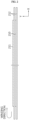
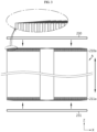
- FIGS. 1 to 3 are diagrams showing a process of manufacturing a tab-less cylindrical battery.
- FIG. 1 shows the structure of an electrode
- FIG. 2 shows a process of winding the electrode
- FIG. 3 shows a process of welding a current collector to a bent surface of an uncoated region.
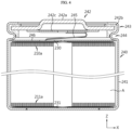
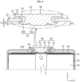
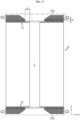
- FIG. 4 is a sectional view showing a tab-less cylindrical battery, that is outside the scope of the invention, taken along the longitudinal direction Y.
- a positive electrode plate 210 and a negative electrode plate 211 have a structure in which a sheet-shaped current collector 220 is coated with an active material 221, and include an uncoated region 222 at one long side along the winding direction X.
- An electrode assembly A is manufactured by sequentially stacking the positive electrode 210 and the negative electrode 211 together with two sheets of separators 212 as shown in FIG. 2 and then winding them in one direction X. At this time, the uncoated region of the positive electrode 210 and the uncoated region of the negative electrode 211 are arranged in opposite directions.
- An electrode tab is not separately coupled to the positive electrode uncoated region 210a and the negative electrode uncoated region 211a, the current collectors 230, 231 are connected to external electrode terminals, and a current path is formed with a large cross-sectional area along the winding axis direction of electrode assembly A (see arrow), which has an advantage of lowering the resistance of the battery. This is because resistance is inversely proportional to the cross-sectional area of the path through which the current flows.
- the conventional tab-less cylindrical battery 240 includes a battery can 241 and a sealing body 242 as shown in FIG. 4 that is outside the scope of the invention.
- the sealing body 242 includes a cap 242a having a plate shape, a sealing gasket 242b and a connection plate 242c.
- the sealing gasket 242b surrounds the edge of the cap 242a and is fixed by a crimping portion 243.
- the electrode assembly A is fixed in the battery can 241 by a beading portion 244 to prevent vertical movement.
- the positive electrode terminal is the cap 242a of the sealing body 242, and the negative electrode terminal is the battery can 241. Therefore, the current collector 230 coupled to the uncoated region 210a of the positive electrode 210 is electrically connected to the connection plate 242c attached to the cap 242a through lead 245 in a strip form. In addition, the current collector 231 coupled to the uncoated region 211a of the negative electrode 211 is electrically connected to the bottom of the battery can 241.
- the insulator 246 covers the current collector 230 to prevent the battery can 241 and the uncoated region 210a of the positive electrode 210 having different polarities from contacting each other and causing a short circuit.
- the lead 245 of a strip form is used.
- the lead 245 is separately attached to the current collector 230 or is manufactured integrally with the current collector 230.
- the lead 245 is in the form of a thin strip, its sectional area is small, and thus, when a rapid charging current flows, a lot of heat is generated.
- excessive heat generated from the lead 245 is transferred toward the electrode assembly A to shrink the separator 212, which may cause an internal short circuit that is a main cause of thermal runaway.
- the lead 245 also occupies a significant installation space inside the battery can 241. Therefore, the cylindrical battery 240 including the lead 245 has low space efficiency, so there is a limit in increasing the energy density.
- a battery pack mounted to an electric vehicle includes hundreds of cylindrical batteries 240. Accordingly, the inefficiency of the electrical wiring causes considerable inconvenience in the electric vehicle assembling process and the maintenance of the battery pack.
- the form factor of the cylindrical battery is increasing. That is, the diameter and height of the cylindrical battery are increasing compared to the conventional cylindrical batteries having a form factor of 18650, 21700, or the like.
- the increase in the form factor leads to an increased energy density, enhanced safety against thermal runaway, and improved cooling efficiency.
- the energy density of the cylindrical battery may be further increased when the unnecessary space inside the battery can is minimized along with the increase of the form factor. Therefore, components used for electrical insulation between the electrode assembly and the battery can or components used for current collection from the positive electrode and the negative electrode need to be optimally designed to increase the capacity of the battery and lower the overall resistance of the battery.
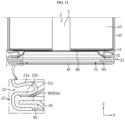
- the present disclosure is designed in consideration of the above problems, and therefore the present disclosure is directed to providing a cylindrical battery having a structure in which a positive electrode terminal and a negative electrode terminal are applied in the same direction.
- the present disclosure is directed to securing a sufficient area for welding an electric connection component such as a bus bar with an electrode terminal of a cylindrical battery while manufacturing a battery pack by utilizing a wide area of a closed portion of a battery can as an electrode terminal, in a case where a plurality of cylindrical batteries are to be electrically connected in one direction.
- the present disclosure is directed to optimally designing so that the area occupied by the upper surface of the terminal (first electrode terminal) and the area occupied by the outer surface (second electrode terminal) of the closed portion may be sufficient for coupling with a bus bar.
- the present disclosure is directed to minimizing the resistance of the cylindrical battery by enlarging a contact area of the electrode assembly and the current collector (first current collector) and/or a contact area of the terminal and the current collector (first current collector) through improvement of the structure of the uncoated region of the electrode assembly.
- the present disclosure is directed to improving the electrical connection structure between the current collector (second current collector) and the battery can to multiplex a current path and directed to maximizing the contact area to minimize the resistance of the cylindrical battery.
- the present disclosure is directed to reducing the current path by improving the electrical connection structure of the current collector (second current collector) and the battery can, thereby minimizing the resistance of the cylindrical battery.
- the present disclosure is directed to minimizing the dead space by improving the structure of the uncoated region of the electrode assembly and/or optimally designing the height of the terminal and/or optimally designing the thickness of the battery can, thereby maximizing the energy density.
- a battery may comprise a rolled electrode assembly, a battery can, a terminal and a cap.
- the rolled electrode assembly may have a first electrode and a second electrode.
- the first electrode may have a first uncoated region.
- the second electrode may have a second uncoated region. Any or both of the first and second uncoated regions may be free of (i.e., not coated with) an active material. Any or both of the first and second uncoated regions may be adjacent to an edge (e.g., disposed at a long side end) of the first electrode and the second electrode, respectively.
- the edge of the first and/or second electrode mayextend along a winding direction of thr olled electrode assembly.
- the battery can accommodate the electrode assembly.
- the battery can be electrically connected to the second uncoated region.
- the battery can may comprise a first end face, a second end face and a sidewall extending between the first end face and the second end face.
- the sidewall of the battery can may be a cylindrical sidewall.
- the second end face may have an opening.
- the terminal may be electrically connected to the first uncoated regrion.
- the terminal may penetrate the first end face of the battery can.
- the cap may cover and/or seal the opening of the second end face of the battery can.
- a battery may comprise: a rolled electrode assembly having a first electrode and a second electrode and a separator interposed therebetween, each of the first electrode and the second electrode having a first uncoated region and a second uncoated region not coated with an active material and exposed out of the separator at long side ends thereof; a battery can accommodating the electrode assembly through an opening at a lower end thereof and electrically connected to the second uncoated region; a terminal electrically connected to the first uncoated region and exposed out of the battery can through a closed portion of the battery can located opposite to the opening; and a cap covering and sealing the opening of the battery can.
- the rolled electrode assembly may comprise a laminate structure in which the positive electrode, the separator and the negative electrode are stacked upon one another.
- the laminate structure may be wound around a winding core to form the rolled electrode assembly.
- the winding core may be empty, filled or partly filled.
- the rolled electrode assembly may have a (generally) cylindrical geometry defining a radial direction, an axial direction and a circumferential (tangential) direction in accordance with the teachings of the mathematical geometry.
- the sidewall of the battery may refer to a lateral face of the battery can that extends in the circumferential and axial directions.
- the first end face and the second end face of the battery can may each extend in the circumferential and radial directions.
- any of the first electrode, the second electrode and the separator may extend between two respective long side ends in the axial direction of the rolled electrode assembly.
- Any of the first electrode, the second electrode and the separator may extend between two respective short side ends in the winding direction (approximately circumferential direction) of the rolled electrode assembly.
- any of the long side ends may be longer than any of the short side ends.
- the expressions long and short may be denominations only, and any of the short side ends may be longer than the long side ends.
- Any of the long side ends may be linear, curved, or patterned (e.g., provided with segments as described below) or a combination thereof.
- the long side end of any of the first and second electrodes and the separator may correspond to a longer or longest side end of any of the sheet-shaped first and second electrodes and separator.
- an edge of the rectangle formed by any of the unrolled first and second electrodes and separator corresponding to the longer side of the rectangle may correspond to a respective "long side end".
- the long side end of any of the first and second electrodes and separator may hence be perpendicular to a height direction of the battery. In said direction perpendicular to the height of the battery, the uncoated portion of the respective electrode may protrude from and/or extend beyond the separator.
- the second electrode may comprise a plate, sheet or film, on which the active material of the second electrode is coated, e.g., by depositing or spraying said active material onto the plate, sheet or film of the first electrode.
- the first electrode may be coated or covered with the active material except for the uncoated region, which may be referred to as second uncoated region.
- the second uncoated region may be formed at (along) one of the long side ends of the second electrode.
- the second electrode may be a positive electrode. Alternatively, the second electrode may be a negative electrode. If the first electrode is a positive electrode, the second electrode may be a negative electrode, and vice versa.
- the active material of the second electrode may be different from the active material of the second electrode.
- the plate, sheet or film of the second electrode may comprise a metal.
- the metal of the second electrode may be different from the metal of the first electrode.
- the battery can have a (generally, or approximately) cylindrical shape.
- the battery can may have a hollow inner volume to accommodate the rolled electrode assembly.
- the battery can may be considered as a case or housing for the rolled electrode assembly.
- the batter can may have a (approximately) cylindrical geometry. According to the cylindrical geometry, the battery can may have an axial direction, a radial direction and a circumferential (tangential) direction. Said directions may be similar or identical with the respective direction of the (approximately) cylindrical geometry of the electrode assembly.
- the battery can may have any of the features of the battery can as described below with reference to the drawings.
- the first end face of the battery can be partly or mostly closed.
- the first end face of the battery can may refer to the geometric construct (in terms of mathematical geometry) and may not be entirely solid.
- the first end face of the battery can may be referred to as a closed portion.
- the first end face may comprise an opening, for example in a central part in a plan view (i.e., when viewed in the axial direction of the battery can).
- the opening in/of the first end face of the battery can may extend through a full thickness of the battery can at the first end face (i.e., be a through-hole).
- the terminal of the battery may pass through the opening in/of the first end face of the battery can.
- the opening in the first end face may have a circular or a polygonal cross-section.
- the first end face of the battery can may have any of the features of the closed portion as described below with reference to the drawings.
- the second end face of the battery can be open (void, empty) for a major part.
- the second end face of the battery can may refer to the geometric construct (in terms of mathematical geometry) and may be solid only at a boundary (periphery, edge), which may be implemented by a round region as described below.
- the second end face of the battery can may have an opening, or may be itself referred to as an opening of the battery can (in a simplifying manner).
- the opening may form a central part, or the major part, of the second end face in a plan view (i.e., when viewed in the axial direction of the battery can).
- the opening of the second end face of the battery can may extend through a full thickness of the battery can at the second end face (i.e., be a through-opening).
- the opening of the second end face of the battery may be configured such that the electrode assembly may be inserted through the opening of the second end face of the battery can.
- the opening in the second end face may have a circular or a polygonal cross-section.
- the second end face of the battery can may have any of the features of an opening of the battery can as described below with reference to the drawings.
- the sidewall of the battery can may be referred to as a cylindrical sidewall of the battery can.
- the sidewall may completely surround the electrode assembly accommodated in the battery can.
- the sidewall of the battery can may provide a cylindrical lateral face of the battery can, which may also be referred to as an outer circumferential surface.
- a portion of the sidewall may be further deformed (e.g., press-fitted) in order to form a beading portion that extends inwardly in a radial direction.
- the sidewall of the battery may have any of the features of the sidewall or the outer circumferential surface as described below with reference to the drawings.
- the cap may be dimensioned and/or arranged such to close the opening of the second end face of the battery can.
- the cap may comprise a venting portion for releasing gas when a predetermined pressure is reached inside the battery can.
- the cap may also be referred to as a cap plate.
- the cap may have any of the features of the cap as described below with reference to the drawings.
- the cap may (be configured to) have no polarity.
- the polarity may indicate a chemical potential equal to a chemical potential at any of the first electrode and the second electrode.
- the cap may be electrically insulated from any or both of the first electrode and the second electrode.
- the terminal may (be configured to) penetrate a center of the closed portion.
- the closed portion may refer to the first end face of the battery can.
- the terminal may penetrate the first end face of the battery can.
- the terminal may arranged such as to extend through the first end face of the battery can.
- the terminal may be arranged through the opening in the first end face of the battery can.
- the battery may further comprise an insulating gasket.
- the insulating gasket may be interposed between the battery can and the terminal.
- the insulating gasket may be provided at the closed portion side of the battery can.
- the battery may further comprise a sealing gasket.
- the sealing gasket may be interposed between the battery can and the cap such that the cap seals the opening may be provided at the opening side of the battery can.
- the sealing gasket may be interposed such that the cap seals the opening of the second end face of the battery can.
- the insulating gasket may have any of the features of the insulating gasket as described below with reference to the drawings.
- the sealing gasket may have any of the features of the sealing gasket as described below with reference to the drawings.
- the first bus bar terminal may overlap with, or lie on or contact, the first electrode terminal on a plane to form a first overlapping region.
- the second bus bar terminal may overlap with, or lie on or contact, the second electrode terminal on a plane to form a second overlapping region.
- An area of (occupied by) the first electrode terminal may be 2% to 30% compared to an area of (occupied by) the second electrode terminal. Any of these areas may refer to a plan view as viewed parallel to the axial direction of the battery can.
- a ratio obtained by dividing a diameter of the battery by a height thereof may be greater than 0.4.
- the ratio may be referred to as a form factor ratio.
- the diameter and the height may be determined in accordance with the cylindrical geometry of the battery can.
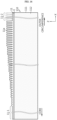
- At least a part of the first uncoated region may include multiple (a plurality of) segments divided along a winding direction of the electrode assembly.
- the multiple (plurality of) segments may be bent along a radial direction of the electrode assembly.
- the segments may be (referred to as) separate or distinct parts of the first uncoated region of first electrode.
- the first uncoated region may be in parts notched in a repetitive and distinctive manner to form the segments.
- the first uncoated may be repeatedly cut from its edge (i.e., from the long side edge of the first electrode) inwards in the axial direction of the rolled electrode assembly to form the segments.
- the cutting or notching may be performed or present in any way as decribed below with reference to the drawings.
- the segments may have any of the features as decribed below with reference to the drawings.
- the winding direction may be along an edge of any of the first electrode, the second electrode and the separator that runs around the winding center of the rolled electrode assembly. Accordingly, the winding direction of the electrode assembly may be a spiral. Approximately, the winding direction of the electrode assembly may be considered substantially identical with the circumferential (tangential) direction of the electrode assembly.
- the multiple bent segments may overlap one another to form multiple overlapping layers extending along the radial direction.
- the plurality of bent segments may be overlapped in multiple layers along the radial direction.
- the electrode assembly may include a welding target region in which the number of overlapping layers of the segments of the first uncoated region is (kept) constant along the radial direction of the electrode assembly.
- the welding target region may be a region or an area which a current collector (for example any of the first and second current collector described below) is, or can be, welded to.
- the welding target region may be provided by bending the segments such as to provide a (subtantially) planar or flat surface of neighboring segments of the first uncoated region.
- the planar surface may face (substantially) in the axial direction.
- At least a part of the second uncoated region may include multiple (a plurality of) segments divided along a winding direction of the electrode assembly, and the multiple segments may be bent along a radial direction of the electrode assembly.
- the plurality of bent segments may be overlapped in multiple layers along the radial direction.
- the electrode assembly may include a welding target region in which the number of overlapping layers of the segments of the second uncoated region is (kept) constant along the radial direction of the electrode assembly.
- the welding target region may be a region or an area which a current collector (for example any of the first and second current collector described below) is, or can be, welded to.
- the welding target region may be provided by bending the segments such as to provide a (subtantially) planar or flat surface of neighboring segments of the second uncoated region.
- the planar surface may face (substantially) in the axial direction.
- the battery can be made of steel, stainless steel, and/or nickel-plated steel.
- a thickness of the sidewall of the battey can be smaller than a thickness of the first end face of the battery can, which may be the closed portion.
- the first end face of the battery can i.e., the closed portion may have a thickness of 0.4 mm to 1.2 mm.
- the sidewall of the battery can may have a thickness of 0.3 mm to 0.8 mm.
- a nickel-plated layer formed on the battery can is formed on the battery can.
- the nickel-plated layer may have a thickness of 1.5 ⁇ m to 6.0 ⁇ m.
- the battery can may include a round region that connects between the sidewall and the first end face (the closed portion) of the battery can.
- the round region may form an edge between the sidewall of the battery can and the first end face of the battery can.
- the round region may surround the first end face.
- the round region may have an annular shape.
- the round region may have any of the features as described below with reference to the drawings.
- the battery can may include a beading portion formed by press-fitting a periphery of the sidewall, i.e., the outer circumferential surface, of the battery can at the second end face of the battery can.
- a beading portion formed by press-fitting a periphery of the sidewall, i.e., the outer circumferential surface, of the battery can at the second end face of the battery can.
- at the second end face may indicate near, or close to, the second end face in the axial direction.
- the beading portion may form a circumferential indentation, recess or groove that extends inwardly from the sidewall of the battery in the radial direction.
- the beading portion may include an upper beading portion and a lower beading portion located above and below, respectively, of an innermost portion in the radial direction.
- the innermost portion may refer to a portion located at an innermost side along the pressing-fitting direction.
- the upper beading portion and the lower beading portion may be parts of the beading portion facing in the opposite axial direction.
- the upper beading portion may be proximal to the first end face of the battery can.
- the lower beading portion may be proximal to the second end face of the battery can.
- the upper beading portion and the lower beading portion may be asymmetric.
- the upper beading portion and the lower beading portion may be asymmetric with respect to a plane perpendicular to the axial direction.
- the upper beading portion and the lower beading portion may be asymmetric to each other.
- the lower beading portion may include a flat portion parallel to the first end face, i.e., the closed portion, of the battery can.
- the upper beading portion may be at least partially inclined in an axial directionfrom the sidewall of the battery can to the innermost portion of the beading portion.
- the upper beading portion may be inclined, bent or curved toward the first end face or the second end face.
- the upper beading portion may be configured to press and/or fix a lower portion of the electrode assembly.
- the upper beading portion may be shaped, arranged and/or dimensioned such as to press and/or fix an end face of the rolled electrode assembly.
- the battery can include a crimping portion formed below the beading portion and having a shape extending and bent from the beading portion to surround an outer circumferential surface of the cap and a part of a lower surface of the cap.
- the crimping portion may have any of the features of the crimping portion as described below with reference to the drawings.
- the battery may include a sealing gasket interposed between the battery can and the cap at the crimping portion.
- the sealing gasket may have any of the features of the sealing gasket as described below with reference to the drawings.
- the cap may include a venting portion configured to be ruptured when an internal pressure of the battery can increases over a predetermined level to discharge gas generated inside the battery can.
- the venting portion may have any of the features of the venting portion as described below with reference to the drawings.
- the venting portion may be a region of the cap having a smaller thickness than surrounding regions.
- the venting portion may be a region of the cap having a reduced thickness compared to a rest of the cap.
- the venting portion may be formed along a periphery of an edge portion of a central region protruding downward, among the entire region of the cap.
- the venting portion may be formed around a central region that protrudes from a rest of the cap in a direction opposite to the first end face of the battery can.
- the venting portion may be formed continuously.
- the venting potion may be discontinuous.
- the venting portion may be formed in a central region protruding downward, among the entire region of the cap, and the central region protruding downward may be located higher than a lower end of the battery can.
- the venting portion may be formed in a central region of the cap and protrude from the cap in the axial direction opposite to the first end face of the battey can.
- the central region may be offset from the second end face of the battery can towards the first end face of the battery can.
- the terminal may include a terminal exposing portion exposed out of the battery can.
- the terminal may include a terminal insert portion provided through the closed portion of the battery can and located inside the battery can.
- the terminal insert portion may extend through the first end face of the battery can into the battery can.
- the terminal insert portion may include an electric connection portion electrically connected to the first uncoated region; and a flange portion formed at a periphery of the electric connection portion and having a shape bent toward an inner surface of the first end face (the closed portion) of the battery can so as to be riveted on the inner surface.
- the terminal may be made of aluminum.
- a step may be formed between an upper surface of the terminal exposing portion and the first end face (which may also be referred to as an upper surface) of the battery can.
- the step may be (referred to as) an edge or a ridge.
- the step may surround the terminal exposing portion.
- the step may be a boundary between the terminal exposing portion and the upper surface of the battery can.
- the step may be formed by a difference of positions of the terminal exposing portion and the first end face (the upper surface) of the battery can in the axial direction.
- the terminal exposing portion may protrude from the battery can through the first end face of the battery can.
- the height of the step may be 0.8 mm or more.
- the height of the step may be a measure in the axial direction between the first end face of the battery can and the terminal exposing portion.
- An insulating gasket may be interposed between the terminal and the battery can, and the insulating gasket may include a gasket exposing portion interposed between the terminal exposing portion and the battery can; and a gasket insert portion interposed between the terminal insert portion and the battery can.
- the insulating gasket, the gasket exposing portion and the gasket insert portion may each have any of the the respective features as described below with reference to the drawings.
- the gasket exposing portion may have a thickness of 0.3 mm to 1 mm.
- the gasket exposing portion may extend longer than the terminal exposing portion such as to be exposed out of the terminal exposing portion.
- the gasket insert portion may be deformed with (as, together when) the flange portion of the terminal insert portion being (is) riveted, so as to be fixed to (and/or in close contact with, seal against, adhere to) an inner surface of the first end face (the closed portion) of the battery can.
- a region of the gasket insert portion (gasket exposing portion) exposed out of the terminal exposing portion may extend by (have a width of) 0.1 mm to 3.0 mm. This may be measured in the radial direction.
- the battery includes a first current collector coupled to an end face (an upper portion) of the electrode assembly and coupled to the terminal so as to electrically connect between the first uncoated region of the electrode assembly and the terminal.
- the end face of the electrode assembly may be proximal to the first end face of the battery can.
- the terminal comprises a flat portion. At least a part of a bottom surface of the terminal is formed as the flat portion parallel to an inner surface of the first end face (the closed portion) of the battery can.
- the flat portion is formed in at least a part of a bottom surface of the terminal.
- the first current collector is coupled to the flat portion of the terminal.
- the first current collector may be coupled onto a coupling surface formed by bending an end of the first uncoated region.
- the battery may include a first current collector coupled to an upper portion of the electrode assembly and coupled to the terminal to electrically connect the first uncoated region of the electrode assembly and the terminal.
- the first current collector may be coupled to the first uncoated region inside the welding target region as specified above or described below with reference to the drawings.
- the first current collector may include an edge portion disposed on the electrode assembly; a first uncoated region coupling portion configured to extend inward from the edge portion and coupled to the first uncoated region; and a terminal coupling portion configured to extend inward from the edge portion and coupled to the terminal.
- the edge portion, the first uncoated region coupling portion and the terminal coupling portion may each have any of the respective features described below with reference to the drawings.
- the first uncoated region coupling portion and the terminal coupling portion may be connected via (through) the edge portion.
- the first uncoated region coupling portion and the terminal coupling portion may be not directly connected but indirectly connected by the edge portion.
- the edge portion may connect the first uncoated region coupling portion with the terminal coupling portion.
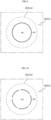
- the terminal coupling portion may be provided at a location corresponding to a hole formed at a winding center of the electrode assembly.
- the winding center may result from the winding of the laminate structure of the electrode assembly as described above.
- the winding center may be at least partially hollow (empty, void), thereby forming said hole in a plan view in the axial direction.
- the winding center may be substantially (approximately) cylindrical.
- the hole may have a circular shape in the plan view.
- the terminal coupling portion may be dimensioned and arranged to fully cover the hole.
- the terminal coupling portion may be configured to cover the hole formed at the winding center so that the hole formed at the winding center of the electrode assembly is not exposed out of the terminal coupling portion.
- the terminal coupling portion may have a diameter substantially equal to or greater than a diameter of the flat portion as specified above and described below with reference to the drawings.
- the first current collector may further include a bridge portion extending between the edge portion and the terminal coupling portion.
- the bridge portion may connect between the edge portion and the terminal coupling portion.
- the bridge portion may extend in the radial direction.
- the bridge portion may include a notching portion formed to locally reduce a cross-section of the bridge portion.
- the cross-section may refer to a plan in the axial and radial direction.
- the bridge portion may comprise any of the features of the bridge portion described below with reference to the drawings.
- At least a part of the first uncoated region may include multiple (a plurality of) segments divided along a winding direction of the electrode assembly, and the segments may be bent along a radial direction of the electrode assembly form multiple overlapping layers.
- the notching portion may be provided in a region corresponding to a welding target region in which the number of overlapping layers of the segments of the first uncoated region is (kept) constant.
- the segments may be as specified above and may comprise any features of the segments as described below with reference to the drawings.
- the welding target region may be as specified above and may comprise any features of the welding target region as described below with reference to the drawings.
- the notching portion may be provided at a location corresponding to a center in the radial direction of the electrode assembly.
- a welding pattern drawn by welding beads formed on one surface of the terminal coupling portion of the first current collector may (be drawn to) surround a center of a bottom surface of the terminal.
- the welding pattern may comprise any of the features of the welding pattern as described below with reference to the drawings.
- the welding pattern may be formed continuously.
- the welding pattern may be discontinuous.
- the terminal coupling portion of the first current collector and a bottom surface (e.g., the flat surface) of the terminal may be welded such as to have a tensile force of 19.6 N (2 kgf) or more.
- a welding pattern drawn by welding beads formed on one surface of the terminal coupling portion of the first current collector may have a converted diameter of 2 mm or more.
- a flat portion formed at the bottom surface of the terminal may have a diameter of 3 mm to 14 mm.
- the flat portion may be as specified above.
- a ratio of an area of a welding pattern drawn by welding beads formed on one surface of the terminal coupling portion of the first current collector to an area of a flat portion formed at the bottom surface of the terminal may be 2.04% to 44.4%.
- the battery may include a second current collector coupled to another end face (a lower portion) of the electrode assembly.
- the second current collector may be coupled to the battery can so as to electrically connect between the second uncoated region of the electrode assembly and the battery can.
- the other end face of the electrode assembly may be proximal to the second end face of the battery can.
- the battery may include a second current collector coupled to a lower portion of the electrode assembly and coupled to the battery can to electrically connect the second uncoated region of the electrode assembly and the battery can.
- the second current collector may be coupled to the second uncoated region inside the welding target region as specified above.
- the second current collector may include a second uncoated region coupling portion coupled to the second uncoated region; and a can coupling portion coupled to the battery can.
- the second current collector and the battery can may be electrically connected at multiple locations.
- the battery can may include a beading portion formed by press-fitting the sidewall (the outer circumferential surface) of the battery can at the second end face.
- the can coupling portion of the second current collector may be electrically coupled to a lower surface of the beading portion.
- the lower surface of the beading portion may be as specified above.
- the battery can may include a crimping portion formed below the beading portion and having a shape extending and bent from the beading portion to surround an outer circumferential surface of the cap and a part of a lower surface of the cap.
- the battery may include a sealing gasket interposed between the battery can and the cap at the crimping portion.
- the can coupling portion may be interposed between the sealing gasket and the lower surface of the beading portion.
- the crimping portion and the sealing gasket may each have any of the respective features as described below with reference to the drawings.
- the beading portion may comprise a flat portion parallel to the first end face (the closed portion) on the lower surface of the beading portion.
- the can coupling portion may be electrically coupled onto the flat portion.
- the can coupling portion may include a contact portion coupled onto an inner surface of the battery can; and a connection portion connecting between a center of the second current collector and the contact portion.
- the contact portion and the connection portion may each have any of the features as described below with reference to the drawings.
- the battery can may include a beading portion formed by press-fitting the sidewall (the outer circumferential surface) of the battery can at the second end face.
- the contact portion may have a shape extending by a predetermined length along a circumferential direction of the battery can on the beading portion.
- the beading portion may be as specified above.
- the second current collector may have a current collector hole formed at a location corresponding to a hole formed at a winding center of the electrode assembly.
- the current collector hole may have any of the features of the current collector hole as described below with reference to the drawings.
- the current collector hole may have a diameter substantially equal to or greater than the hole formed at the winding center of the electrode assembly.
- the battery can may include the beading portion as specified above.
- a maximum distance from a center of the second current collector to an end of the second uncoated region coupling portion along the radial direction of the electrode assembly may be substantially equal to or smaller than an inner diameter of the battery can in a region where the beading portion is formed.
- the battery may further comprise an insulator interposed between the first current collector and an inner surface of the first end face (the closed portion) of the battery can.
- the insulator may have a thickness corresponding to the distance between the inner surface of the first end face (the closed portion) of the battery can and the first current collector.
- the terminal may be coupled to the first current collector through a hole formed in the insulator.
- the insulator may have a thickness substantially equal to or greater than the distance between the inner surface of the first end face (the closed portion) of the battery can and a bottom surface of the terminal.
- the insulator may be interposed between the first uncoated region and a sidewall of the battery can.
- An upper surface of the insulator may be in contact with the inner surface of the closed portion of the battery can, and a lower surface of the insulator may be in contact with an upper surface of the first current collector.
- Resistance measured between a positive electrode and a negative electrode of the battery may be 4 m ⁇ or below, 3 m ⁇ or less, or 2 m ⁇ or less.
- the resistance may be at least 0.5 m ⁇ , or 1.0 m ⁇ or more.
- a battery pack comprising a plurality of batteries according to the present disclosure.
- the plurality of batteries may be arranged in a predetermined number of columns, and the terminal of each cylindrical battery and an outer surface of the closed portion of the battery can may be disposed to face upward.
- the battery pack may comprise multiple (a plurality of) bus bars configured to connect the batteries in series and/or in parallel.
- the bus bars may be disposed on top of the batteries.
- Each of the bus bars may include a body portion configured to extend between terminals of neighboring batteries; multiple first bus bar terminals configured to extend in one side direction of the body portion and electrically coupled to a terminal of a battery located in the one side direction; and multiple second bus bar terminals configured to extend in the other side direction of the body portion and electrically coupled to an outer surface of the closed portion of the battery can of a battery located in the other side direction.
- a vehicle comprising at least one battery pack according to the present disclosure.
- an electrical wiring operation for serial and/or parallel connection of the batteries may be performed at one side of the batteries.
- the contact area of the electrode assembly and the current collector (first current collector) and/or the contact area of the terminal and the current collector (first current collector) may be enlarged, thereby minimizing the resistance of the cylindrical battery.
- the current path may be multiplexed through improvement of the electrical connection structure of the current collector (second current collector) and the battery can, and the contact area between these parts may be maximized to minimize the resistance of the cylindrical battery.
- the substantially identical objects may include deviations considered low in the art, for example, deviations within 5%. Also, when it is explained that certain parameters are uniform in a predetermined region, this may mean that the parameters are uniform in terms of an average.
- a cylindrical battery 1 includes an electrode assembly 10, a battery can 20, a cap 30, and a penetrating terminal 40.
- the cylindrical battery 1 may further include an insulation gasket 50 and/or a first current collector 60 and/or an insulator 70 and/or a second current collector 80 and/or a sealing gasket 90.
- the electrode assembly 10 includes a first electrode having a first polarity, a second electrode having a second polarity, and a separator interposed between the first electrode and the second electrode.
- the first electrode is a positive electrode or a negative electrode
- the second electrode corresponds to an electrode having a polarity opposite to that of the first electrode.
- the electrode assembly 10 may have, for example, a jelly-roll structure. That is, the electrode assembly 10 may be manufactured by preparing a stack that is formed by stacking a first electrode and a second electrode having a sheet shape at least once with a separator interposed therebetween, and winding the stack based on a winding center C. In this case, an additional separator may be provided on an outer circumferential surface of the electrode assembly 10 for insulation from the battery can 20.
- the jelly-roll structure known in the art can be applied to the present disclosure without limitations.
- the first electrode includes a first electrode current collector and a first electrode active material coated on one surface or both surfaces of the first electrode current collector. At one end of the first electrode current collector in a width direction (parallel to the Z-axis), there is an uncoated region that is not coated with the first electrode active material.
- the uncoated region functioning as a first electrode tab 11 will be called the first uncoated region 11.
- the first uncoated region 11 is provided at an upper portion of the electrode assembly 10 accommodated in the battery can 20 in a height direction (parallel to the Z-axis).
- the first uncoated region 11 may include a plurality of segments divided along a winding direction of the electrode assembly 10.
- the plurality of segments may be bent along a radial direction of the electrode assembly 10.
- the plurality of bent segments may be overlapped in multiple layers.
- a first uncoated region coupling portion 62 of the first current collector 60 explained later, may be coupled to a region in which the plurality of segments are overlapped in multiple layers.
- the electrode assembly 10 may include a welding target region that is a region in which the number of overlapping layers of the segments of the first uncoated region 11 is kept constant along the radial direction of the electrode assembly 10.
- the first current collector 60 explained later, and the first uncoated region 11 are welded in this region. This is, for example, in the case of applying laser welding, to prevent the laser beam from passing through the first uncoated region 11 and damaging the electrode assembly 10 when the output of the laser is increased, in order to improve welding quality. In addition, this is to effectively prevent foreign substances such as welding spatters from flowing into the electrode assembly 10.
- the second electrode includes a second electrode current collector and a second electrode active material coated on one surface or both surfaces of the second electrode current collector. At the other end of the second electrode current collector in the width direction (parallel to the Z-axis), there is an uncoated region that is not coated with the second electrode active material.
- the uncoated region functioning as a second electrode tab 12 will be called the second uncoated region 12.
- the second uncoated region 12 is provided at a lower portion of the electrode assembly 10 accommodated in the battery can 20 in the height direction (parallel to the Z-axis).
- the second electrode current collector includes a second uncoated region 12 that is not coated with an active material layer at a long side end thereof and is exposed out of the separator, and at least a part of the second uncoated region 12 is used as an electrode tab by itself.
- the second uncoated region 12 may be, for example, a negative electrode tab.
- at least a part of the second uncoated region 12 may include a plurality of segments divided along the winding direction of the electrode assembly 10. In this case, the plurality of segments may be bent along the radial direction of the electrode assembly 10. The plurality of bent segments may be overlapped in multiple layers.
- a second uncoated region coupling portion 82 of the second current collector 80 may be coupled to a region in which the plurality of segments are overlapped in multiple layers.
- the electrode assembly 10 may include a welding target region that is a region in which the number of overlapping layers of the segments of the second uncoated region 12 is kept constant along the radial direction of the electrode assembly 10. In this region, since the number of overlapping layers is kept to the maximum, it may be advantageous that the second current collector 80, explained later, and the second uncoated region 12 are welded within this region.
- the first uncoated region 11 and the second uncoated region 12 extend in opposite directions along the height direction (parallel to the Z-axis) of the cylindrical battery 1.
- the first uncoated region 11 extends toward a closed portion located opposite to an opening formed at the lower end of the battery can 20, and the second uncoated region 12 extends toward the opening of the battery can 20.
- the positive electrode active material may include an alkali metal compound expressed by a general formula A[A x M y ]O 2+z (A includes at least one element among Li, Na and K; M includes at least one element selected from is Ni, Co, Mn, Ca, Mg, Al, Ti, Si, Fe, Mo, V, Zr, Zn, Cu, Al, Mo, Sc, Zr, Ru, and Cr; x ⁇ 0, 1 ⁇ x+y ⁇ 2, -0.1 ⁇ z ⁇ 2; and the stoichiometric coefficients x, y and z are selected so that the compound maintains electrical neutrality).
- A includes at least one element among Li, Na and K
- M includes at least one element selected from is Ni, Co, Mn, Ca, Mg, Al, Ti, Si, Fe, Mo, V, Zr, Zn, Cu, Al, Mo, Sc, Zr, Ru, and Cr
- the positive electrode active material may be an alkali metal compound xLiM 1 O 2 -(1-x)Li 2 M 2 O 3 disclosed in US6,677,082 , US6,680,143 , et al., wherein M 1 includes at least one element having an average oxidation state 3; M 2 includes at least one element having an average oxidation state 4; and 0 ⁇ x ⁇ 1).
- the positive electrode active material may be lithium metal phosphate expressed by a general formula Li a M 1 x Fe 1-x M 2 y P 1-y M 3 z O 4-z
- M 1 includes at least one element selected from the Ti, Si, Mn, Co, Fe, V, Cr, Mo, Ni, Nd, Al, Mg and Al
- M 2 includes at least one element selected from Ti, Si, Mn, Co, Fe, V, Cr, Mo, Ni, Nd, Al, Mg, Al, As, Sb, Si, Ge, V and S
- M 3 includes a halogen element optionally including F; 0 ⁇ a ⁇ 2, 0 ⁇ x ⁇ 1, 0 ⁇ y ⁇ 1, 0 ⁇ z ⁇ 1; the stoichiometric coefficients a, x, y and z are selected so that the compound maintains electrical neutrality), or Li 3 M 2 (PO 4 ) 3 (M includes at least one element selected from Ti, Si, Mn, Fe, Co, V,
- the positive electrode active material may include primary particles and/or secondary particles in which the primary particles are aggregated.
- the negative electrode active material may employ carbon material, lithium metal or lithium metal compound, silicon or silicon compound, tin or tin compound, or the like.
- Metal oxides such as TiO 2 and SnO 2 with a potential of less than 2V may also be used as the negative electrode active material.
- As the carbon material a low-crystalline carbon and/or a high-crystalline carbon may be used.
- the separator may employ a porous polymer film, for example, a porous polymer film made of a polyolefin-based polymer such as ethylene homopolymer, propylene homopolymer, ethylene/butene copolymer, ethylene/hexene copolymer, ethylene/methacrylate copolymer, or the like, or laminates thereof.
- a porous polymer film for example, a porous polymer film made of a polyolefin-based polymer such as ethylene homopolymer, propylene homopolymer, ethylene/butene copolymer, ethylene/hexene copolymer, ethylene/methacrylate copolymer, or the like, or laminates thereof.
- the separator may employ a common porous nonwoven fabric, for example, a nonwoven fabric made of high melting point glass fiber, polyethylene terephthalate fiber, or the like.
- a coating layer of inorganic particles may be included in at least one surface of the separator. It is also possible that the separator itself is made of a coating layer of inorganic particles. Particles in the coating layer may be coupled with a binder so that an interstitial volume exists between adjacent particles.
- the inorganic particles may be made of an inorganic material having a dielectric constant of 5 or more.
- the inorganic particles may include at least one material selected from the group consisting of Pb(Zr,Ti)O 3 (PZT), Pb 1-x La x Zr 1-y Ti y O 3 (PLZT), PB(Mg 3 Nb 2/3 )O 3 -PbTiO 3 (PMN-PT), BaTiO 3 , hafnia (HfO 2 ), SrTiO 3 , TiO 2 , AL 2 O 3 , ZrO 2 , SnO 2 , CeO 2 , MgO, CaO, ZnO and Y 2 O 3 .
- the electrolyte may be a salt having a structure like A + B - .
- A+ includes an alkali metal cation such as Li+, Na + , or K+, or a combination thereof.
- B - includes at least one anion selected from the group consisting of F-, Cl-, Br-, I-, NO 3 - , N (CN) 2 - , BF 4 - , ClO 4 - , AlO 4 - , AlCl 4 - , PF 6 - , SbF 6 - , AsF 6 - , BF 2 C 2 O 4 - , BC 4 O 8 - , (CF 3 ) 2 PF 4 - , (CF 3 ) 3 PF 3 - , (CF 3 ) 4 PF 2 - , (CF 3 ) 5 PF - , (CF 3 ) 6 P - , CF 3 SO 3 -- , C 4 F 9 SO 3 - , CF 3 CF
- the electrolyte may also be dissolved in an organic solvent.
- the organic solvent may employ propylene carbonate (PC), ethylene carbonate (EC), diethyl carbonate (DEC), dimethyl carbonate (DMC), dipropyl carbonate (DPC), dimethyl sulfoxide, acetonitrile, dimethoxyethane, diethoxyethane, tetrahydrofuran, N-methyl-2-pyrrolidone (NMP), ethyl methyl carbonate (EMC), ⁇ -butyrolactone, or a mixture thereof.
- PC propylene carbonate
- EC ethylene carbonate
- DEC diethyl carbonate
- DMC dimethyl carbonate
- DPC dipropyl carbonate
- dimethyl sulfoxide acetonitrile, dimethoxyethane, diethoxyethane, tetrahydrofuran, N-methyl-2-pyrrolidone (NMP), ethyl methyl carbonate (
- the battery can 20 is a substantially cylindrical container having an opening at a lower side, and is made of, for example, a material having conductivity such as metal.
- a material of the battery can 20 for example, steel, stainless steel or nickel-plated steel may be applied.
- the bottom of the battery can 20 having the opening will be referred to as an opened end.
- the upper surface located opposite to the opening (or, the opened end) will be referred to as a closed portion or a closed end.
- a side surface (outer circumferential surface) and an upper surface of the battery can 20 may be integrally formed.
- the sidewall and the closed portion of the battery can 20 may be provided separately from each other and be coupled to each other by welding or the like.
- the upper surface of the battery can 20 (a surface parallel to the X-Y plane), namely an outer surface 20a of the closed portion, has an approximately flat shape.
- the battery can 20 accommodates the electrode assembly 10 through the opening formed at the bottom, and also accommodates an electrolyte together.
- the battery can 20 is electrically connected to the electrode assembly 10.
- the battery can 20 is electrically connected to, for example, the second uncoated region 12 of the electrode assembly 10.
- the battery can 20 has the same polarity as the second uncoated region 12.
- the battery can 20 may include a beading portion 21 and a crimping portion 22 formed at a lower end thereof.
- the beading portion 21 is located below the electrode assembly 10.
- the beading portion 21 is formed by press-fitting a periphery of the outer circumferential surface of the battery can 20.
- the upper beading portion 21a and the lower beading portion 21b respectively located above and below based on an innermost portion 21c of the beading portion 21 located at an innermost side along the pressing-fitting direction may have an asymmetric shape.
- This asymmetric shape may be formed in the process of compressing the battery can 20 along the height direction (parallel to the Z-axis) through a sizing process.
- the sizing process is a process of matching the height of the cylindrical battery 1 to a design form factor by pressing the battery can 20 along the winding axis direction of the electrode assembly 10.
- the lower beading portion 21b may include a flat portion substantially parallel to the closed portion of the battery can 20. Meanwhile, due to the asymmetrical formation, the upper beading portion 21a may have a shape inclined upward at least partially along a direction toward the innermost portion 21c. Accordingly, the upper beading portion 21a may compress and fix the lower portion of the electrode assembly 10.
- the beading portion 21 prevents the electrode assembly 10 having a size approximately corresponding to the inner diameter of the battery can 20 from coming out through the opening formed at the lower end of the battery can 20, and may function as a support portion on which the cap 30 is placed.
- the lower beading portion 21b may function as a support portion for fixing the contact portion 83a of the second current collector 80, the sealing gasket 90, and the like as well as the cap 30, explained later.
- the crimping portion 22 is formed below the beading portion 21.
- the crimping portion 22 extends from the lower beading portion 21.
- the crimping portion 22 has a shape extending and bent to surround the outer circumferential surface of the cap 30 disposed below the beading portion 21 and a part of the lower surface of the cap 30.
- the crimping portion 22 may fix the sealing gasket 90 in addition to the cap 30.
- the present disclosure does not exclude the case where the battery can 20 does not include the beading portion 21 and/or the crimping portion 22.
- the battery can 20 does not include the beading portion 21 and/or the crimping portion 22, it is possible to fix the electrode assembly 10 and/or fix the cap 30 and/or seal the battery can 20 by, for example, additionally applying a component that can function as a stopper for the electrode assembly 10 and/or additionally applying a structure on which the cap 30 can be placed and/or welding the battery can 20 and the cap 30 to each other.
- the battery can 20 may be configured to have different thicknesses depending on locations.
- the thickness of the sidewall may be formed smaller than the thickness of the closed portion.
- the electrode assembly 10 since the electrode assembly 10 may be formed to have a greater diameter, it may be advantageous in terms of energy density.
- the sidewall constituting the outer circumferential surface may have, for example, a thickness in the range of about 0.3 mm to 0.8 mm, more preferably in the range of about 0.4 mm to 0.6 mm. If the thickness of the sidewall of the battery can 20 is too small, the possibility of fire spreading to neighboring cylindrical batteries 1 increase when fire and explosion occurs at the cylindrical battery 1. For example, in a battery pack including a plurality of cylindrical batteries 1, in the case where an abnormality occurs in some cylindrical batteries 1 to cause fire and explosion, if the thickness of the sidewall of the battery can 20 is too small, a pin hole may be generated, thereby increasing the risk of a chain ignition and explosion.
- the cap 30 may be made of, for example, a metal material to ensure rigidity.
- the cap 30 seals the opening (or, the opened end) formed at a bottom end of the battery can 20. That is, the cap 30 functions as the lower surface of the cylindrical battery 1.
- the cap 30 may not have a polarity even if it is made of a conductive metal material.
- the cap 30 having no polarity may mean that the cap 30 is not electrically connected to the electrode assembly 10. If the cap 30 is not electrically connected to the electrode assembly 10 as above, the cap 30 does not function as a positive electrode terminal or a negative electrode terminal. That is, in the present disclosure, the cap 30 does not need to be electrically connected to the electrode assembly 10 and the battery can 20, and its material does not necessarily have to be a conductive metal.
- the cap 30 may be supported by the lower surface of the beading portion 21 formed on the battery can 20.
- the cap 30 is fixed by the crimping portion 22. That is, the upper surface of the cap 30 may be supported by the beading portion 21, and the outer circumferential surface and the lower surface of the cap 30 may be supported by the beading portion 21.
- the sealing gasket 90 may be interposed between the cap 30 and the crimping portion 22 of the battery can 20 to secure the airtightness of the battery can 20.
- the cap 30 may further include a venting portion 31 formed to prevent an inner pressure from increasing over a preset value due to a gas generated inside the battery can 20.
- the preset inner pressure value may be about 1471 kPa (15 kgf/cm 2 ) to 3432 kPa (35 kgf/cm 2 ).
- the venting portion 31 corresponds to a region having a smaller thickness compared to the peripheral region of the cap 30.
- the venting portion 31 is structurally weak compared to the peripheral region. Accordingly, if an abnormal situation occurs in the cylindrical battery 1 so that the inner pressure of the battery can 20 increases over a certain level, the venting portion 31 is ruptured so that the gas generated inside the battery can 20 is discharged.
- the venting portion 31 may be formed by reducing the thickness of the battery can 20 partially, for example by notching any one surface or both surfaces of the cap 30.
- the venting portion 31 may have a shape extending continuously or discontinuously to surround the central region of the cap 30 as shown in FIGS. 13 and 14 .
- a greater distance is advantageous from the center of the cap 30 to the venting portion 31 in terms of ease of rupture of the venting portion 31 due to the increase of internal pressure. This is because, when the same internal pressure is applied, as the distance from the center point of the cap 30 to the venting portion 31 is greater, the force acting on the venting portion 31 increases further to secure easy rupture.
- a greater distance is also advantageous from the center point of the cap 30 to the venting portion 31 in terms of the smooth discharge of the venting gas since the area opened by venting is increased.
- the venting portion 31 may be advantageously formed along an edge circumference of the central region having an approximately flat shape and protruding downward (in a lower direction based on FIG. 13 ), in the entire region of the cap 30.
- FIGS. 13 and 14 depict a case in which the venting portion 31 is continuously formed in an approximately circular shape on the cap 30, but the present disclosure is not limited thereto.
- the venting portion 31 may have an approximately elliptical shape or other geometric shape that is formed to include the center point of the cap 30 therein.
- the venting portion 31 may be formed discontinuously instead of continuously.
- the terminal 40 is made of a metal material with conductivity.
- the material of the terminal 40 may be aluminum (Al). If the material of the terminal 40 is aluminum, the riveting process, explained later, may be performed easily, and aluminum of 10 series having a relatively low electrical resistance may be applied.
- the terminal 40 penetrates an upper surface of the battery can 20, namely a surface (parallel to the XY plane) located at a side of the battery can 20 opposite to the opening.
- the terminal 40 is electrically connected to the first uncoated region 11 of the electrode assembly 10, for example. In this case, the terminal 40 has a first polarity. Accordingly, the terminal 40 may function as a first electrode terminal in the cylindrical battery 1 of the present disclosure.
- the terminal 40 is electrically insulated from the battery can 20 with the second polarity.
- the electrical insulation between the terminal 40 and the battery can 20 may be realized in various ways.
- the insulation may be realized by interposing an insulation gasket 50, explained later, between the terminal 40 and the battery can 20.
- the insulation may be realized by forming an insulating coating layer on a portion of the terminal 40.
- any method of structurally fixing the terminal 40 securely such that the terminal 40 and the battery can 20 cannot contact each other may be applied.
- some of the above methods may be applied together.
- the terminal 40 includes a terminal exposing portion 41 and a terminal insert portion 42.
- the terminal insert portion 42 may include an electric connection portion 42a and a flange portion 42b.
- the terminal exposing portion 41 is exposed out of the battery can 20.
- the terminal exposing portion 41 may be located approximately at the center of the closed portion of the battery can 20.
- the maximum width of the terminal exposing portion 41 may be formed larger than the maximum width of the hole formed in the battery can 20 for the insertion of the terminal 40.
- the terminal insert portion 42 may pass through approximately the center of the closed portion of the battery can 20, and the electric connection portion 42a of the terminal insert portion 42 may be electrically connected to the first uncoated region 11.
- the flange portion 42b of the terminal insert portion 42 is formed at the periphery of the electric connection portion 42a, and may be riveted on the inner surface of the closed portion of the battery can 20. That is, the flange portion 42b of the terminal insert portion 42 may have a shape curved toward the inner surface of the closed portion of the battery can 20. Therefore, the maximum width of the terminal insert portion 42 after the riveting process for fixing the terminal 40 is performed may be formed larger than the maximum width of the hole formed in the battery can 20 so that the terminal insert portion 42 passes therethrough.
- the electric connection portion 42a of the terminal insert portion 42 is coupled to the first current collector 60.
- the electric connection portion 42a of the terminal insert portion 42 may have, for example, a substantially cylindrical shape.
- the shape of the electric connection portion 42a of the terminal insert portion 42 is not limited thereto.
- the electric connection portion 42a of the terminal insert portion 42 may have various shapes, such as, for example, a cylindrical shape having an elliptical cross-section, a square pillar shape, a hexagonal pillar shape, an octagonal pillar shape, or the like.
- the bottom surface of the electric connection portion 42a of the terminal insert portion 42 may be formed to be substantially flat at least partially.
- the bottom surface of the central region of the terminal insert portion 42 and the first current collector 60 may be coupled by, for example, laser welding, spot welding or ultrasonic welding.
- the welding may be performed by irradiating a laser through a hole formed at the winding center C of electrode assembly 10 or inserting a tool for ultrasonic welding or spot welding to form a welding bead W on one surface of the first current collector 60 (a surface facing the hole formed at the winding center C of the electrode assembly 10).
- a guide pipe (not shown) for welding may be inserted into the hole formed at the winding center C.
- the diameter of the flat portion formed on the bottom surface of the electric connection portion 42a of the terminal insert portion 42 may be determined in consideration of welding strength with the first current collector 60.
- the tensile force of the welding portion between the flat portion and the first current collector 60 may be at least about 19.6 N (2 kgf) or more, 29.4 N (3 kgf) or more, 39.2 N (4 kgf) or more, 49.0 N (5 kgf) or more, 58.8 N (6 kgf) or more, 68.6 N (7 kgf) or more, 78.5 N (8 kgf) or more, 88.3 N (9 kgf) or more, or 98.1 N (10 kgf) or more. It is preferable to increase the tensile force of the welding portion as much as possible within an allowable range by optimally selecting a welding method.
- the diameter (or, the maximum width) of the welding pattern formed on the flat portion to satisfy the tensile force condition of the welding portion may be at least about 2 mm.
- the diameter of the welding pattern may be defined as a converted diameter (2*(S/ ⁇ ) 0.5 ) of a circle when the area (S) of the welding bead W displayed on the surface of the welding portion is converted to an area ( ⁇ r 2 ) of the corresponding circle.
- the flat portion formed on the bottom surface of the electric connection portion 42a of the terminal insert portion 42 corresponds to a weldable region.
- the diameter of the weldable region may be approximately 3 mm to 14 mm. If the diameter of the weldable region is less than about 3 mm, it is difficult to secure a welding pattern with a diameter (converted diameter) of 2 mm or more. In particular, in the case of forming a welding pattern using laser welding, it is difficult to secure a welding pattern having a diameter of 2 mm or more due to laser beam interference.
- the diameter of the weldable region exceeds approximately 14 mm, the diameter of the terminal exposing portion 41 of the terminal 40 is inevitably increased beyond that, and thus it is difficult to sufficiently secure the area of the outer surface 20a of the battery can 20 to be used as an electrode terminal having an opposite polarity to the terminal 40.
- the ratio of the area of the welding pattern to the area of the weldable region required to secure a welding portion tensile force of at least about 49.0 N (5 kgf) or more is preferably approximately 2.04% ( ⁇ 1 2 / ⁇ 7 2 ) to 44.4% ( ⁇ 1 2 / ⁇ 1.5 2 ).
- the diameter of the arc welding pattern is about 2 mm or more, preferably about 4 mm or more.
- the diameter of the arc welding pattern satisfies the corresponding condition, it is possible to secure sufficient welding strength by increasing the welding portion tensile force to about 49.0 N (5 kgf) or more.
- the diameter of the circular welding pattern is preferably about 2 mm or more.
- the diameter of the circular welding pattern satisfies the corresponding condition, it is possible to secure sufficient welding strength by increasing the welding portion tensile force to about 49.0 N (5 kgf) or more.
- the diameter of the flat portion formed on the bottom surface of the terminal 40 corresponding to the weldable region may be adjusted in the range of approximately 3 mm to 14 mm. If the radius of the flat portion is less than about 3 mm, it is difficult to form a welding pattern having a diameter of about 2 mm or more by using a laser welding tool, an ultrasonic welding tool, or the like.
- the distance from the center of the upper surface of the terminal 40 to the outermost side, namely the radius R1 of the terminal exposing portion 41, may be approximately 10% to 70% of the radius (R2, 1/2 of the outer diameter of the battery can) of the upper surface of the battery can 20. If R1 decreases, the welding space becomes insufficient when welding components (bus bars) used for the electrical connection of the terminal 40. In addition, when R1 increases, the welding space decreases when welding components (bus bars) used for electrical connection in a remaining area except for the terminal 40 on the upper surface of the battery can 20.
- the welding space for the terminal 40 and the welding space for the outer surface 20a of the closed portion of the battery can 20 may be properly secured.
- the radius R3 of the bottom surface of the electric connection portion 42a of the terminal insert portion 42 may be approximately 4% to 30% compared to the R2.
- R3 should be smaller than R1, and if R3 increases, the thickness of the flange portion 42b of the terminal insert portion 42 inevitably decreases, which weakens the force of the flange portion 42b to compress the insulating gasket 50, thereby deteriorating the sealing ability of the insulating gasket 50.
- the welding process may be easily performed by sufficiently securing the welding area between the bottom surface of the electric connection portion 42a of the terminal insert portion 42 and the first current collector 60, and also it is possible to reduce the contact resistance of the welding area and to prevent the sealing ability of the insulating gasket 50 from deteriorating.
- the cylindrical battery 1 has a structure in which the bottom surface of the electric connection portion 42a of the terminal insert portion 42 is welded onto the first current collector 60 as described above, thereby maximizing the binding area between the first current collector 60 and the terminal 40. That is, at least a part of the bottom surface of the electric connection portion 42a is formed to be flat, and thus the coupling area between the terminal 40 and the first current collector 60 may be maximized. Therefore, the cylindrical battery 1 according to an embodiment of the present disclosure may secure a smooth current flow at the coupling portion of the first current collector 60 and the terminal 40 in the case where a large amount of current flows due to rapid charging, thereby giving the effects of shortening the charging time and reducing the amount of heat generated.
- the upper surface of the battery can 20, namely the outer surface 20a of the closed portion of the battery can 20, and the upper surface of the terminal exposing portion 41 of the terminal 40 exposed out of the battery can 20 have opposite polarities and face in the same direction.
- a step may be formed between the upper surface of the terminal exposing portion 41 and the upper surface of the battery can 20. That is, as shown in FIGS. 7 and 8 , the terminal exposing portion 41 may protrude to the outside of the battery can 20 by a predetermined height through the upper surface of the battery can 20. In this case, the height of the step may be in the range of approximately 0.08 mm to 4 mm.
- the upper surface of the battery can 20 may be located higher than the terminal exposing portion 41 of the electrode terminal 40.
- the upper surface of the battery can 20 has a shape concavely indented from the center downward, namely toward the electrode assembly 10
- the upper surface of the battery can 20 and the upper surface of the terminal exposing portion 41 may form the same plane according to the indented depth and the thickness of the terminal exposing portion 41 of the electrode terminal 40.
- a step may not be formed between the upper surface of the battery can 20 and the upper surface of the terminal exposing portion 41.
- the insulation gasket 50 is interposed between the battery can 20 and the terminal 40 to prevent the battery can 20 and the terminal 40 having opposite polarities from contacting each other. Accordingly, the upper surface of the battery can 20 having an approximately flat shape may function as a second electrode terminal of the cylindrical battery 1.
- the insulation gasket 50 includes a gasket exposing portion 51 and a gasket insert portion 52.
- the gasket exposing portion 51 is interposed between the terminal exposing portion 41 of the terminal 40 and the battery can 20.
- the gasket exposing portion 51 may extend longer than the terminal exposing portion 41, and thus may be exposed out of the terminal exposing portion 41 when the cylindrical battery 51 is viewed from the above.
- the gasket insert portion 52 is interposed between the terminal insert portion 42 of the terminal 40 and the battery can 20. When the flange portion 42b of the terminal insert portion 42 is riveted, the gasket insert portion 52 may be deformed together to come into close contact with the inner surface of the closed portion of the battery can 20.
- the insulation gasket 50 may be made of, for example, a resin material having insulation and elasticity.
- the gasket exposing portion 51 of the insulation gasket 50 may have an extended shape to cover the outer circumferential surface of the terminal exposing portion 41 of the terminal 40. If the insulation gasket 50 covers the outer circumferential surface of the terminal 40 in this way, it is possible to prevent a short circuit from occurring in the process of coupling an electric connection component such as a bus bar to the upper surface of the battery can 20 and/or the terminal 40.
- the gasket exposing portion 51 of the insulation gasket 50 may also have an extended shape to cover not only the outer circumferential surface of the terminal exposing portion 41 but also a portion of the upper surface thereof.
- the insulation gasket 50 may be coupled to the battery can 20 and the terminal 40 by thermal fusion. In this case, the airtightness at the coupling interface between the insulation gasket 50 and the terminal 40 and at the coupling interface between the insulation gasket 50 and the battery can 20 may be strengthened. Meanwhile, in the case where the gasket exposing portion 51 of the insulation gasket 50 extends to the upper surface of the terminal exposing portion 41, the terminal 40 may be coupled to the insulation gasket 50 by insert injection molding.
- the height H3 of the flange portion 42a of the terminal insert portion 42 protruding to the inside of the battery can 20 may be approximately 0.5 mm to 3.0 mm. If the protrusion height H3 of the terminal insert portion 42 is less than about 0.5 mm, it is difficult to ensure sufficient sealing properties. In addition, if the protrusion height H3 of the terminal insert portion 42 exceeds 3 mm, the internal space of the battery can 20 that can be occupied by the electrode assembly 10 is reduced.
- the total height of the terminal 40 may be approximately 1.5 mm to 7 mm.
- the total height of the terminal 40 means the distance from the upper surface of the terminal exposing portion 41 to the bottom surface of the terminal insert portion 42. If the total height of the terminal 40 is less than about 1.5 mm, it is difficult to increase the thickness of the gasket insert portion 52 enough to secure sealing properties due to the thickness of the closed portion of the battery can 20.
- the thickness of the closed portion of the battery can 20 may be formed in the range of about 0.4 mm to 1.2 mm.
- the inner space of the battery can 20 that can be occupied by the electrode assembly 10 is excessively reduced and the total height of the cylindrical battery 1 is increased, so that the energy density per unit area is lowered as much.
- the terminal 40 may have a riveted structure such that the terminal insert portion 42 is substantially parallel to the inner surface of the closed portion of the battery can 20. Accordingly, the angle formed by and the inner surface of the closed portion and the surface of the terminal insert portion 42 opposite to the inner surface of the closed portion of the battery can 20 may be formed substantially close to zero.
- the height H3 of the flange portion 42b of the terminal insert portion 42 protruding toward the inside of the battery can 20 with respect to the inner surface of the closed portion of the battery can 20 may be formed equal to or greater than the height H2 of the gasket insert portion 52 protruding toward the inside of the battery can 20.
- the height H1 of the electric connection portion 42a protruding toward the inside of the battery can 20 with respect to the inner surface of the closed portion of the battery can 20 may be equal to or greater than the protrusion height H3 of the flange portion 42b.
- the inner edge portion of the hole of the battery can 20 for the passage of the terminal 40 and the insulating gasket 50 has an arc shape with a predetermined curvature.
- the electric connection portion 42a of the terminal insert portion 42 of the terminal 40 may have a shape gradually narrowing toward its bottom surface.
- the thickness of the insulating gasket 50 may gradually decrease downward from an intermediate region where the gasket exposing portion 51 and the gasket insert portion 52 are connected, and then slightly increase at the distal end of the gasket insert portion 52.
- the compression structure of the insulating gasket 50 may further improve the sealing properties for the space between the terminal 40 and the battery can 20.
- the riveting structure of the terminal 40 according to an embodiment of the present disclosure as described above may be applied to a cylindrical battery having a form factor greater than 21700.
- the form factor of the cylindrical battery is increasing compared to the conventional 18650, 21700, and the like.
- An increase in the form factor leads to increased energy density, increased safety against thermal runaway, and improved cooling efficiency.
- the cylindrical battery 1 to which the riveting structure of the terminal 40 is applied may perform all electrical wiring for the positive electrode/negative electrode in one direction.
- the terminal 40 having the riveting structure as described above has a large sectional area and low electric resistance, which is very advantageous for rapid charging.
- the entire area of the upper surface of the battery can 20 viewed from a location above the cylindrical battery 1, the entire area except for the area occupied by the terminal 40 and the insulation gasket 50 corresponds to the second electrode terminal having the opposite polarity to the terminal 40.
- the cylindrical sidewall of the battery can 20 may be formed in one piece with the second electrode terminal so that there is no discontinuous portion therebetween.
- the connection portion from the sidewall of the battery can 20 to the second electrode terminal may have a smooth curve. That is, a round region may be provided at the edge circumference of the upper surface 20a of the battery can 20.
- the connecting portion may include at least one corner having a predetermined angle.
- a region occupied by the terminal 40 and the insulating gasket 50 and the entire region except for the round region may function as a second electrode terminal having a polarity opposite to the terminal 40.
- the first current collector 60 is coupled to an upper portion of the electrode assembly 10.
- the first current collector 60 is coupled to the terminal 40. That is, the first current collector 60 electrically connects the first uncoated region 11 of the electrode assembly 10 and the terminal 40.
- the first current collector 60 is made of a metal material with conductivity and is connected to the first uncoated region 11.
- the first current collector 60 may include a plurality of unevenness radially formed on a lower surface thereof. If the unevenness is formed, the unevenness may be pressed into the first uncoated region 11 by pressing the first current collector 60.
- a flat portion approximately parallel to the inner surface of the closed portion of the battery can 20 is formed in at least part of the bottom surface of the terminal 40, namely the bottom surface of the electric connection portion 42a of the terminal insert portion 42, and the first current collector 60 is coupled to the flat portion.
- the first current collector 60 is coupled to an end of the first uncoated region 11.
- the coupling between the first uncoated region 11 and the first current collector 60 may be performed, for example, by laser welding.
- the laser welding may be performed by partially melting a base material of the first current collector 60, or may be performed in a state where a solder for welding is interposed between the first current collector 60 and the first uncoated region 11.
- the solder preferably has a lower melting point than the first current collector 60 and the first uncoated region 11.
- the first current collector 60 may be coupled to a coupling surface of the first uncoated region 11, which is formed by bending an end of the first uncoated region 11 in a direction parallel to the first current collector 60.
- the bending direction of the first uncoated region 11 may be, for example, a direction toward the winding center C, namely core, of the electrode assembly 10. If the first uncoated region 11 has a bent shape as above, the space occupied by the first uncoated region 11 may be reduced, thereby improving energy density.
- the coupling force may be improved and the resistance may be reduced.
- the first current collector 60 applied to the present disclosure may include an edge portion 61, a first uncoated region coupling portion 62, and a terminal coupling portion 63.
- the edge portion 61 is disposed on the electrode assembly 10.
- the edge portion 61 may have a substantially rim shape having an empty space S formed therein. In the drawings of the present disclosure, only a case in which the edge portion 61 has a substantially circular rim shape is illustrated, but the present disclosure is not limited thereto.
- the edge portion 61 may have a substantially rectangular rim shape, a hexagonal rim shape, an octagonal rim shape, or other rim shapes, unlike the illustrated one.
- the terminal coupling portion 63 may have a diameter substantially equal to or greater than the diameter of the flat portion formed on the bottom surface of the terminal 40 in order to secure a welding area for coupling with the flat portion formed on the bottom surface of the terminal 40.
- the first uncoated region coupling portion 62 extends inward from the edge portion 61 and is coupled to the first uncoated region 11.
- the terminal coupling portion 63 is spaced apart from the first uncoated region coupling portion 62 and is located inside the edge portion 61.
- the terminal coupling portion 63 may be coupled to the terminal 40 by welding.
- the terminal coupling portion 63 may be located approximately at the center of the inner space, for example, surrounded by the edge portion 61.
- the terminal coupling portion 63 may be provided at a location corresponding to the hole formed at the winding center C of the electrode assembly 10.
- the terminal coupling portion 63 may be configured to cover the hole formed at the winding center C of the electrode assembly 10 so that the hole formed at the winding center C of the electrode assembly 10 is not exposed out of the terminal coupling portion 63. If the hole formed at the winding center C of the electrode assembly 10 is covered as above, it is possible to prevent that the separator positioned inside the hole is damaged due to the flow rate of the electrolyte passing through the hole and thus the electrode is leaked. To this end, the terminal coupling portion 63 may have a larger diameter or width than the hole formed at the winding center C of the electrode assembly 10.
- the first uncoated region coupling portion 62 and the terminal coupling portion 63 may not be directly connected, but may be disposed to be spaced apart from each other and indirectly connected by the edge portion 61. Since the first current collector 60 has a structure in which the first uncoated region coupling portion 62 and the terminal coupling portion 63 are not directly connected to each other but are connected through the edge portion 61 as above, when shock and/or vibration occurs at the cylindrical battery 1, it is possible to disperse the shock applied to the coupling portion between the first uncoated region coupling portion 62 and the first uncoated region 11 and the coupling portion between the terminal coupling portion 63 and the terminal 40.
- first uncoated region coupling portions 62 are provided in the drawings of the present disclosure, but the present disclosure is not limited thereto.
- the number of the first uncoated region coupling portions 62 may be variously determined in consideration of manufacturing difficulty according to the complexity of the shape, electric resistance, the space inside the edge portion 61 considering electrolyte impregnation, and the like.
- the first current collector 60 may further include a bridge portion 64 extending inward from the edge portion 61 and connected to the terminal coupling portion 63. At least a part of the bridge portion 64 may have a smaller sectional area compared to the first uncoated region coupling portion 62 and the edge portion 61. For example, at least a part of the bridge portion 64 may be formed to have a smaller width and/or thickness compared to the first uncoated region coupling portion 62. In this case, the electric resistance increases in the bridge portion 64, and thus when a current flows through the bridge portion 64, the relatively large resistance causes a part of the bridge portion 64 to be melted due to overcurrent heating, which irreversibly blocks the overcurrent.
- the sectional area of the bridge portion 64 may be adjusted to an appropriate level in consideration of the overcurrent blocking function.
- the bridge portion 64 may include a taper portion 64a whose width is gradually decreased from the inner surface of the edge portion 61 toward the terminal coupling portion 63.
- the rigidity of the component may be improved at the connection portion between the bridge portion 64 and the edge portion 61.
- a transfer device and/or a worker may easily and safely transport the first current collector 60 and/or a coupled body of the first current collector 60 and the electrode assembly 10 by gripping the taper portion 64a. That is, when the taper portion 64a is provided, it is possible to prevent product defects that may occur by gripping a portion where welding is performed with other components such as the first uncoated region coupling portion 62 and the terminal coupling portion 63.
- the first uncoated region coupling portion 62 may be provided in plural.
- the plurality of first uncoated region coupling portions 62 may be disposed substantially at regular intervals from each other in the extending direction of the edge portion 61.
- An extension length of each of the plurality of first uncoated region coupling portions 62 may be substantially equal to each other.
- the first uncoated region coupling portion 62 may be coupled to the first uncoated region 11 by welding.
- the terminal coupling portion 63 may be disposed to be surrounded by the plurality of first uncoated region coupling portions 62.
- the terminal coupling portion 63 may be coupled to the terminal 40 by welding.
- the bridge portion 64 may be positioned between a pair of first uncoated region coupling portions 62 adjacent to each other. In this case, the distance from the bridge portion 64 to any one of the pair of first uncoated region coupling portions 62 along the extending direction of the edge portion 61 may be substantially equal to the distance from the bridge portion 64 to the other one of the pair of first uncoated region coupling portions 62 along the extending direction of the edge portion 61.
- the plurality of first uncoated region coupling portions 62 may be formed to have substantially the same sectional area.
- the plurality of first uncoated region coupling portions 62 may be formed to have substantially the same width and thickness.
- the bridge portion 64 may be provided in plural. Each of the plurality of bridge portions 64 may be disposed between a pair of first uncoated region coupling portions 62 adjacent to each other. The plurality of bridge portions 64 may be disposed substantially at regular intervals to each other in the extending direction of the edge portion 61. A distance from each of the plurality of bridge portions 64 to one of the pair of first uncoated region coupling portions 62 adjacent to each other along the extending direction of the edge portion 61 may be substantially equal to a distance from each of the plurality of the bridge portion 64 to the other first uncoated region coupling portion 62.
- first uncoated region coupling portion 62 and/or the bridge portion 64 is provided in plural as described above, if the distance between the first uncoated region coupling portions 62 and/or the distance between the bridge portions 64 and/or the distance between the first uncoated region coupling portion 62 and the bridge portion 64 is uniformly formed, a current flowing from the first uncoated region coupling portion 62 toward the bridge portion 64 or a current flowing from the bridge portion 64 toward the first uncoated region coupling portion 62 may be smoothly formed.
- the first current collector 60 and the first uncoated region 11 may be coupled by welding.
- welding for example, laser welding, ultrasonic welding, spot welding, or the like may be applied.
- the bridge portion 64 may include a notching portion N formed to partially reduce a sectional area of the bridge portion 64.
- the sectional area of the notching portion N may be adjusted, for example, by partially reducing the width and/or thickness of the bridge portion 64.
- the notching portion N may be located closer to the taper portion 64a than the terminal coupling portion 63. Heat is generated relatively more in the narrowest part of the taper portion 64a, and thus the notching portion N adjacent to the taper portion 64a may quickly cut off the overcurrent.
- the notching portion N is preferably provided in a region corresponding to the welding target region of the electrode assembly 10 described above in order to prevent foreign substances such as welding spatters generated during rupturing from flowing into the electrode assembly 10. This is because, in this region, the first uncoated region 11 maintains the maximum number of overlapping layers of segments and thus the overlapped segments may function as a mask.
- the notching portion N may be provided at approximately the center in the radial direction of the electrode assembly 10.
- the insulator 70 is provided between a top end of the electrode assembly 10 and the inner surface of the battery can 20 or between the first current collector 60 coupled to the upper portion of the electrode assembly 10 and the inner surface of the closed portion of the battery can 20.
- the insulator 70 prevents contact between the first uncoated region 11 and the battery can 20 and/or contact between the first current collector 60 and the battery can 20.
- the insulator 70 may also be interposed between a top end of the outer circumferential surface of the electrode assembly 10 and the sidewall of the battery can 20. That is, the insulator 70 may also be interposed between the uncoated region 11 and the sidewall of the battery can 20.
- the first current collector 60 may be a plate extending completely across the top of the outer circumferential surface of the electrode assembly 10. However, the present disclosure is not limited thereto, and the first current collector 60 may be formed to extend across the top of the outer circumferential surface of the electrode assembly 10 only partially.
- the terminal insert portion 42 of the terminal 40 is coupled to the first current collector 60 or the first uncoated region 11 through the insulator 70.
- the hole formed in the insulator 70 may be formed at a location corresponding to the hole formed at the winding center C of the electrode assembly 10.
- the hole formed in the insulator 70 may be formed at a location corresponding to the terminal coupling portion 63 of the first current collector 60.
- the electrode assembly 10 may be damaged.
- the flat portion formed at the lower end of the terminal 40 coupled to the terminal coupling portion 43 may be located substantially at the same height as the lower surface of the insulator 70 or located higher. In this case, the welding portion between the terminal 40 and the first current collector 60 is located outside the hole formed at the winding center C of the electrode assembly 10.
- the thickness of the insulator 70 may have a thickness substantially equal to or greater than the distance from the inner surface of the closed portion of the battery can 20 to the flat portion provided at the lower end of the terminal 40. Meanwhile, the insulator 70 may have a thickness corresponding to the distance between the inner surface of the closed portion of the battery can 20 and the first current collector 60 by filling the space between the inner surface of the closed portion of the battery can 20 and the first current collector 60 along the height direction so that a space where the electrode assembly 10 can move is not generated.
- the upper surface of the insulator 70 may be in contact with the inner surface of the closed portion of the battery can 20, and the lower surface of the insulator 70 may be in contact with the upper surface of the first current collector 60.
- the second current collector 80 is disposed below the electrode assembly 10.
- the second current collector 80 may be configured to electrically connect the second uncoated region 12 of the electrode assembly 10 and the battery can 20.
- the second current collector 80 is made of a metal material with conductivity and is connected to the second uncoated region 12.
- the second current collector 80 is electrically connected to the battery can 20.
- the second current collector 80 may be interposed and fixed between the inner surface of the battery can 20 and the sealing gasket 90. More specifically, the second current collector 80 may be interposed between the lower surface of the beading portion 21 of the battery can 20 and the sealing gasket 90.
- the present disclosure is not limited thereto.
- the second current collector 80 may be welded to the inner wall surface of the battery can 20 in a region where the beading portion 21 is not formed.
- the second current collector 80 may include a plurality of unevenness radially formed on one surface thereof. If the unevenness is formed, the unevenness may be pressed into the second uncoated region 12 by pressing the second current collector 80.
- the second current collector 80 is coupled to an end of the second uncoated region 12.
- the coupling between the second uncoated region 12 and the second current collector 80 may be performed, for example, by laser welding.
- the laser welding may be performed by partially melting a base material of the second current collector 80, or may be performed in a state where a solder for welding is interposed between the second current collector 80 and the second uncoated region 12.
- the solder preferably has a lower melting point than the second current collector 80 and the second uncoated region 12.
- the second current collector 80 may be coupled to a coupling surface of the second uncoated region 12, which is formed by bending an end of the second uncoated region 12 in a direction parallel to the second current collector 80.
- the bending direction of the second uncoated region 12 may be, for example, a direction toward the winding center C, namely the core, of the electrode assembly 10. If the second uncoated region 12 has a bent shape as above, the space occupied by the second uncoated region 12 may be reduced, thereby improving energy density.
- the coupling force may be improved and the resistance may be reduced.
- FIG. 15 an exemplary form of the second current collector 80 of the present disclosure is shown. Referring to FIG. 15 along with FIG. 13 , the second current collector 80 electrically connects the electrode assembly 10 and the battery can 20.
- the second current collector 80 may include a support portion 81 disposed below the electrode assembly 10, a second uncoated region coupling portion 82 extending from the support portion 81 approximately along the radial direction of the electrode assembly 10 and coupled to the second uncoated region 12, and a can coupling portion 83 extending from the support portion 81 approximately along the radial direction of the electrode assembly 10 and coupled to the inner surface of the battery can 20.
- the second uncoated region coupling portion 82 and the can coupling portion 83 are indirectly connected through the support portion 81, and are not directly connected to each other.
- the second current collector 80 of the present disclosure is not limited to the structure where the second uncoated region coupling portion 82 and the can coupling portion 83 are only indirectly connected.
- the second current collector 80 may have a structure that does not include the support portion 81 for indirectly connecting the second uncoated region coupling portion 82 and the can coupling portion 83 and/or a structure in which the second uncoated region 12 and the can coupling portion 83 are directly connected to each other.
- the support portion 81 and the second uncoated region coupling portion 82 are disposed below the electrode assembly 10.
- the second uncoated region coupling portion 82 is coupled to the second uncoated region 12 of the electrode assembly 10.
- the support portion 81 may also be coupled to the second uncoated region 12.
- the second uncoated region coupling portion 82 and the second uncoated region 12 may be coupled by welding.
- the support portion 81 and the second uncoated region coupling portion 82 are located higher than the beading portion 21 when the beading portion 21 is formed on the battery can 20.
- the support portion 81 has a current collector hole 80a formed at a location corresponding to the hole formed at the winding center C of the electrode assembly 10.
- the hole of the electrode assembly 10 and the current collector hole 80a communicating with each other may function as a passage for inserting a welding rod for welding between the terminal 40 and the terminal coupling portion 63 of the first current collector 60 or for irradiating a laser beam.
- the current collector hole 80a may have a diameter substantially equal to or greater than the hole formed at the winding center C of the electrode assembly 10.
- the plurality of second uncoated region coupling portions 82 may have a shape extending approximately radially from the support portion 81 of the second current collector 80 toward the sidewall of the battery can 20.
- Each of the plurality of second uncoated region coupling portions 82 may be positioned to be spaced apart from each other along the periphery of the support portion 81. Meanwhile, in order to secure coupling force and reduce electrical resistance by increasing the coupling area between the second current collector 80 and the electrode assembly 10, not only the second uncoated region coupling portion 82 but also the support portion 81 may be coupled to the second uncoated region 12.
- At least a part of the second uncoated region 12 may be formed in a bent shape such that an end thereof is substantially parallel to the second uncoated region coupling portion 82.
- the second uncoated region 12 may be bent toward the winding center C of the electrode assembly 10, for example. If the end of the second uncoated region 12 is formed as above and coupled to the second uncoated region coupling portion 82 in a state of being parallel to the second uncoated region coupling portion 82, the coupling area is increased, thereby improving coupling force and reducing electric resistance. In addition, by minimizing the total height of the electrode assembly 10, the energy density may be improved. Meanwhile, the bent end of the second uncoated region 12 may be overlapped in multiple layers. If the second uncoated region 12 may be overlapped in multiple layers, the second uncoated region coupling portion 82 of the second current collector 80 may be coupled to a region where the second uncoated region 12 is bent and overlapped in multiple layers.
- the can coupling portion 83 may be provided in plural.
- the plurality of can coupling portions 83 may have a shape extending approximately radially from the center of the second current collector 80 toward the sidewall of the battery can 20. Accordingly, the electrical connection between the second current collector 80 and the battery can 20 may be made at a plurality of points. Since the coupling for electrical connection is made at a plurality of points, the coupling area may be maximized, thereby minimizing electric resistance.
- the plurality of can coupling portions 83 may be positioned to be spaced apart from each other along the periphery of the support portion 81. At least one can coupling portion 83 may be positioned between the second uncoated region coupling portions 82 adjacent to each other.
- the plurality of can coupling portions 83 may be coupled to, for example, the beading portion 21 in the inner surface of the battery can 20.
- the can coupling portions 83 may be coupled, particularly, to the lower surface of the beading portion 21. If this structure is applied to the cylindrical battery 1 of the present disclosure, the can coupling portion 83 may be naturally placed on the lower surface of the beading portion 21 through the process of accommodating the electrode assembly 10 coupled with the second current collector 80 into the battery can 20. Therefore, the battery can 20 and the second current collector 80 may be welded easily.
- the welding for bonding the battery can 20 and the current collector 80 may use, for example, laser welding, ultrasonic welding, or spot welding.
- the resistance level may be limited to about 4 milliohms or less.
- the resistance may be at least 0.5 m ⁇ , or 1.0 m ⁇ , or more.
- the lower surface of the beading portion 21 has a shape extending in a direction approximately parallel to the upper surface of the battery can 20, namely in a direction approximately perpendicular to the sidewall of the battery can 20, and the can coupling portion 83 also has a shape extending in the same direction, namely in the radial direction and the circumferential direction, the can coupling portion 83 may be stably in contact with the beading portion 21.
- the two components may be welded smoothly, thereby improving the coupling force between the two components and minimizing the increase in resistance at the coupling portion.
- the can coupling portion 83 may include a contact portion 83a coupled onto the inner surface of the battery can 20 and a connection portion 83b for connecting the support portion 81 and the contact portion 83a.
- the contact portion 83a is coupled onto the inner surface of the battery can 20.
- the contact portion 83a may be coupled onto the beading portion 21 as described above. More specifically, the contact portion 83a may be electrically coupled to the flat portion formed at the lower surface of the beading portion 21 formed on the battery can 20, and may be interposed between the lower surface of the beading portion 21 and the sealing gasket 90.
- the contact portion 83a may have a shape extending from the beading portion 21 by a predetermined length along the circumferential direction of the battery can 20.
- the maximum distance from the center of the second current collector 80 to the end of the second uncoated region coupling portion 82 along the radial direction of the electrode assembly 10 is preferably substantially equal to or smaller than the inner diameter of the battery can 20 in a region where the beading portion 21 is formed, namely the minimum inner diameter of the battery can 20. This is to prevent interference from occurring between the second current collectors 80 by the beading portion 21 during the sizing process for compressing the battery can 20 along the height direction, and thus to prevent the electrode assembly 10 from being pressed by the second current collector.
- the structure of the electrode assembly 10 will be described in more detail.
- the first electrode will be described as an example among the first and second electrodes described above, but the structure of the first electrode may be equally applied to the second electrode.
- the first electrode 110 includes a first electrode current collector 111 having a sheet shape made of a conductive foil, a first active material layer 112 formed on at least one surface of the first electrode current collector 111, and a first uncoated region 11 formed by not coating an active material at a long side end of the first electrode current collector 111.
- the first uncoated region 11 may include a plurality of notched segments 11a.
- the plurality of segments 11a constitutes a plurality of groups, and the segments 11a included in each group may be identical in terms of the height (length in the Y-axis direction) and/or the width (length in the X-axis direction) and/or the separation pitch.
- the number of segments 11a belonging to each group may be increased or decreased than shown in the drawings.
- the segment 11a has a geometric shape in which at least one straight line and/or at least one curve are combined.
- the segment 11a may have a trapezoidal shape, and may be deformed into a rectangular, parallelogram, semicircular or a semi-elliptical shape.
- the height of the segment 11a may be increased stepwise along one direction parallel to the winding direction of the electrode assembly 10, for example, from the core toward the outer circumference.
- a core-side uncoated region 11-1 adjacent to the core of the electrode assembly 10 may not include the segment 11a, and the core-side uncoated region 11-1 may have a lower height than the uncoated region of other regions.
- an outer circumferential uncoated region 11-2 adjacent to the outer circumference of the electrode assembly 10 may not include the segment 11a, and the outer circumferential uncoated region 11-2 may have a lower height than other uncoated regions.
- the first electrode 110 may include an insulation coating layer E that covers a boundary between the active material layer 112 and the first uncoated region 11.
- the insulation coating layer E includes a polymer resin having an insulation property, and may optionally further include an inorganic filler.
- the insulation coating layer E may function to prevent the end of the active material layer 112 from contacting an active material layer having an opposite polarity facing through the separator, and to structurally support the bending of the segment 11a.
- at least a part of the insulation coating layer E is preferably exposed from the separator to the outside.
- the heights of the uncoated regions 11, 12 change are schematically shown. That is, the heights of the uncoated regions 11, 12 may vary irregularly depending on the location where the cross section is cut. For example, if a side portion of the trapezoidal segment 11a is cut, the height of the uncoated region in the cross section is lower than the height of the segment 11a. Therefore, it should be understood that the heights of the uncoated regions 11, 12 shown in the drawings showing the cross section of the electrode assembly 10 correspond to the average of the heights of the uncoated regions included in each winding turn.
- the hole formed at the core C of the electrode assembly 10 is not closed.
- the hole is not closed, there is no difficulty in the electrolyte injection process, and the electrolyte injection efficiency may be improved.
- by inserting a welding tool through the hole it is possible to easily weld the terminal 40 and the first current collector 60 (see FIG. 7 ).
- the cylindrical battery 1 has a structure in which the cap 30 does not necessarily have polarity, as described above.
- the second current collector 80 is connected to the sidewall of the battery can 20, and thus the outer surface 20a of the closed portion of the battery can 20 has a polarity opposite to the terminal 40. Therefore, when a plurality of cylindrical batteries 1 are to be connected in series and/or in parallel, the wiring work such as connecting a bus bar may be formed at the upper portion of the cylindrical battery 1 using the terminal 40 and the outer surface 20a of the closed portion of the battery can 20. Through this, energy density may be improved by increasing the number of cylindrical batteries 1 that can be mounted in the same space, and electrical wiring may be easily performed.
- the terminal 40 exposed out of the battery can 20 may function as a first electrode terminal, and the region of the outer surface 20a of the closed portion of the battery can 20 occupied by the exposed surface approximately parallel to the upper surface of the first electrode terminal may function as a second electrode terminal. Accordingly, when the plurality of cylindrical batteries 1 are to be electrically connected, a first bus bar may be coupled to the upper surface of the terminal 40 exposed out of the battery can 20, and a second bus bar may be coupled to the region of the outer surface 20a of the closed portion of the battery can 20 occupied by the exposed surface approximately parallel to the upper surface of the first electrode terminal.
- a plurality of cylindrical batteries 1 may be connected in series and in parallel on top of the cylindrical batteries 1 using a bus bar 150.
- the number of cylindrical batteries 1 may be increased or decreased in consideration of the capacity of the battery pack.
- the terminal 40 may have a positive polarity and the outer surface 20a of the closed portion of the battery can 20 may have a negative polarity, or vice versa.
- the plurality of cylindrical batteries 1 may be arranged in a plurality of columns and rows. Columns are provided in a vertical direction with respect to the ground, and rows are provided in a left and right direction with respect to the ground.
- the cylindrical batteries 1 may be arranged in a closest packing structure. The closest packing structure is formed when an equilateral triangle is formed by connecting the centers of the terminal exposing portions 41 of the terminal 40 exposed out of the battery can 20 to each other.
- the bus bar 150 may be disposed on the plurality of cylindrical batteries 1, more preferably between neighboring rows. Alternatively, the bus bar 150 may be disposed between neighboring rows.
- the bus bar 150 connects the cylindrical batteries 1 arranged in the same column in parallel to each other, and connects the cylindrical batteries 1 arranged in two neighboring columns in series with each other.
- the bus bar 150 may include a body portion 151, a plurality of first bus bar terminals 152 and a plurality of second bus bar terminals 153 for serial and parallel connection.
- the body portion 151 may extend between terminals 40 of neighboring cylindrical batteries 70, preferably between rows of the cylindrical batteries 1. Alternatively, the body portion 151 may extend along the row of the cylindrical batteries 1 and may be regularly bent like a zigzag shape.
- the plurality of first bus bar terminals 152 may protrusively extend from one side of the body portion 151 toward the terminal 40 of each cylindrical battery 1 and may be electrically coupled to the terminal 40.
- the electrical connection between the first bus bar terminal 152 and the terminal 40 may be accomplished by laser welding, ultrasonic welding, or the like.
- the plurality of second bus bar terminals 153 may be electrically coupled to the outer surface 20a of each cylindrical battery 1 from the other side of the body portion 151.
- the electrical connection between the second bus bar terminal 153 and the outer surface 20a may be achieved by laser welding, ultrasonic welding, or the like.
- the body portion 151, the plurality of first bus bar terminals 152 and the plurality of second bus bar terminals 153 may be made of one conductive metal plate.
- the metal plate may be, for example, an aluminum plate or a copper plate, but the present disclosure is not limited thereto.
- the body portion 151, the plurality of first bus bar terminals 152 and the second bus bar terminals 153 may be manufactured as separate pieces and then coupled to each other by welding or the like.
- the cylindrical batteries 1 since the terminal 40 having a positive polarity and the outer surface 20a of the closed portion of the battery can 20 having a negative polarity are located in the same direction, the cylindrical batteries 1 may be electrically connected easily using the bus bar 150.
- the coupling area of the bus bar 150 may be sufficiently secured to sufficiently lower the resistance of the battery pack including the cylindrical battery 1.
- the diameter (E 1 ) of the electrode terminal 40 and the width (E 2 ) of the outer surface 20a having a ring shape may be adaptively adjusted in consideration of the dimensions of the contact areas of the bus bar terminals 152, 153.
- the width (E 2 ) of the outer surface 20a of the closed portion of the battery can 20 is the width of the exposed surface parallel to the surface of the electrode terminal 40.
- the width (E 2 ) of the outer surface 20a is defined as the width of a line segment connecting two points where the straight line (L 1 ) drawn in the radial direction from the center C of the electrode terminal 40 intersects inner and outer boundaries of the outer surface 20.
- the width (E 2 ) of the outer surface 20a is the width of the flat exposed surface in the entire upper surface of the battery can 20, excluding the round region R existing at the edge of the closed portion of the battery can 20 and the gasket exposing portion 51 of the insulating gasket 50.
- the closed portion of the battery can 20 may be divided into the terminal 40, the gasket exposing portion 51 of the insulating gasket 50, and the round region R formed at the edge of the outer surface 20a of the closed portion, when viewed from above.
- the round region R is a processing region (see FIGS. 7 and 8 ) for smoothly connecting the closed portion of the battery can 20 and the sidewall of the battery can 20, and has a predetermined width (R d ) on a plane.
- the first bus bar terminal 152 of the bus bar 150 is branched to one side different from the traveling direction of the body portion 151 and is electrically coupled to the terminal exposing portion 41 of the terminal 40.
- the electrode terminal 40 and the first bus bar terminal 152 form a first overlapping region (marked by hatching) on a plane, and the first overlapping region has a first width (W 1 ).
- the first overlapping region is a region where the electrode terminal 40 and the first bus bar terminal 152 overlap on a plane.
- the first width (W 1 ) is defined as a maximum value among distances between any two points selected at the edge of the first overlapping region.
- the definition of the first width (W 1 ) is applied equally to the case where the first overlapping region includes the center of the terminal 40 ( FIG. 22 ) and the case where the first overlapping region does not include the center of the terminal 40 ( FIG. 23 ).
- the distance indicated by W 1 corresponds to a maximum value among distances between any two points selected at the edge of the first overlapping region.
- the second bus bar terminal 153 of the bus bar 150 extends in a direction opposite to the first bus bar terminal 152 based on the traveling direction of the body portion 151 and is electrically coupled to the outer surface 20a of the closed portion of the battery can 20.
- the second bus bar terminal 153 and the outer surface 20a form a second overlapping region (marked by hatching) on a plane, and the second overlapping region has a second width (W 2 ).
- the second overlapping region is a region where the outer surface 20a and the second bus bar terminal 153 overlap on a plane.
- the second width (W 2 ) is defined as a maximum value among distances between two points where each straight line meets an edge of the second overlapping region, when a plurality of straight lines (L 2 ) are drawn from the center C of the terminal exposing portion 41 of the terminal 40 to pass through the second overlapping region.
- the diameter (E 1 ) of the terminal exposing portion 41 of the terminal 40 must be at least equal to or greater than the first width (W 1 ) of the first bus bar terminal 152. This is because the first overlapping region of the first bus bar terminal 152 and the terminal exposing portion 41 must not deviate to the outside of the terminal exposing portion 41 on a plane.
- the diameter (E 1 ) of the terminal 40 may be increased to the maximum until the distance between the boundary of the electrode terminal 40 and the second bus bar terminal 153 corresponds to the width (G) of the gasket exposing portion 51 of the insulating gasket 50. Therefore, the maximum value of the diameter (E 1 ) of the terminal exposing portion 41 of the terminal 40 is 'D-2*R d -2*G-2*W2'.
- the width (E 2 ) of the outer surface 20a is a factor dependent on the diameter (E 1 ) of the terminal exposing portion 41, and must be at least equal to or greater than the second width (W 2 ) of the second bus bar terminal 153. Only in this case, an overlapping region of the second bus bar terminal 153 and the outer surface 20a may be formed.
- the width (E 2 ) of the outer surface 20a may be increased up to 50% of 'D-2*Rd-2*G-E1', which is a value obtained by subtracting the diameter (E 1 ) of the terminal exposing portion 41, the width (2*G) occupied by the gasket exposing portion 51 and the width of the round region (2*R d ) from the outer diameter (D) of the battery can 20.
- the diameter (E 1 ) of the terminal exposing portion 41 of the terminal 40 and the width (E 2 ) of the outer surface 20a are preferably designed to satisfy the following formulas.
- W 2 E 2 0.5 ⁇ D ⁇ 2 R d ⁇ 2 G ⁇ E 1
- E 1 diameter of the terminal 40 exposed out of the battery can 20
- E 2 width of the exposed surface of the outer surface 20a of the closed portion of the battery can 20 approximately parallel to the upper surface of the terminal 40
- D outer diameter of the battery can
- R d width of the round region R measured on a plane
- G exposure width of the insulating gasket 50 exposed out of the terminal 40 located outside the battery can 20
- W 1 width of the first bus bar terminal 152, W 2 : width of the second bus bar terminal 153)
- D is 46 mm
- W 1 and W 2 are 6 mm
- G is 0.5 mm and R d is 1.5 mm
- the diameter (E 1 ) of the terminal exposing portion 41 is 6 mm to 30 mm
- the width (E 2 ) of the outer surface 20a is 6 mm and 18 mm.
- the area occupied by the terminal exposing portion 41 (the area occupied by the first electrode terminal) is preferably about 2% to 30% of the area of the exposed surface of the outer surface 20a of the closed portion of the battery can 20 approximately parallel to the upper surface of the terminal 40 (the area occupied by the second electrode terminal). This is due to the width of the bus bar applied considering that a current in the level of about 300A flows. If the ratio of the area occupied by the terminal exposing portion 41 to the area occupied by the outer surface 20a exceeds the upper limit of the above range, the area may not be sufficient to connect the second bus bar terminal 153 to the outer surface 20a.
- the area occupied by the terminal exposing portion 41 may not be sufficient in connecting the first bus bar terminal 153 to the terminal exposing portion 41.
- the width (R d ) occupied by the gasket exposing portion 51 may be in the range of about 0.1 mm to 3.0 mm, preferably about 0.1 mm to 1.0 mm. If the width (R d ) occupied by the gasket exposing portion 51 is too large, the connection area of the bus bar terminals 152, 153 may not be sufficiently secured. Conversely, if the width (R d ) occupied by the gasket exposing portion 51 is too small, for example if charging and discharging is performed at a high C-rate of 300A or more, the electrical insulation between the terminal 40 and the outer surface 20a of the battery can 20 may be broken on a plane.
- the cylindrical battery may be, for example, a cylindrical battery whose form factor ratio (defined as a value obtained by dividing the diameter of the cylindrical battery by height, namely a ratio of height (H) to diameter ( ⁇ )) is greater than about 0.4.
- form factor ratio defined as a value obtained by dividing the diameter of the cylindrical battery by height, namely a ratio of height (H) to diameter ( ⁇ )
- the form factor means a value indicating the diameter and height of a cylindrical battery.
- the cylindrical battery according to an embodiment of the present disclosure may be, for example, a 46110 cell, a 48750 cell, a 48110 cell, a 48800 cell, or a 46800 cell.
- first two numbers indicate the diameter of the cell
- next two numbers indicate the height of the cell
- the last number "o" indicates that the cross-section of the cell is circular.
- a battery according to an embodiment of the present disclosure may be a cylindrical battery having an approximately cylindrical shape, whose diameter is approximately 46 mm, height is approximately 110 mm, and form factor ratio is 0.418.
- a battery according to another embodiment may be a cylindrical battery having a substantially cylindrical shape, whose diameter is about 48 mm, height is about 75 mm, and form factor ratio is 0.640.
- a battery according to still another embodiment may be a cylindrical battery having an approximately cylindrical shape, whose diameter is approximately 48 mm, height is approximately 110 mm, and form factor ratio is 0.418.
- a battery according to still another embodiment may be a cylindrical battery having an approximately cylindrical shape, whose diameter is approximately 48 mm, height is approximately 80 mm, and form factor ratio is 0.600.
- a battery according to still another embodiment may be a cylindrical battery having an approximately cylindrical shape, whose diameter is approximately 46 mm, height is approximately 80 mm, and form factor ratio is 0.575.
- batteries having a form factor ratio of about 0.4 or less have been used. That is, conventionally, for example, 18650 cell, 21700 cell, etc. were used.
- the 18650 cell has a diameter of approximately 18 mm, height of approximately 65 mm, and a form factor ratio of 0.277.
- the 21700 cell has a diameter of approximately 21 mm, a height of approximately 70 mm, and a form factor ratio of 0.300.
- the cylindrical battery 1 of the present disclosure has a structure in which resistance is minimized by expanding a contact area between components, multiplexing current path, minimizing a current path length, and the like.
- the AC resistance of the cylindrical battery 1 measured using a resistance measuring instrument between the positive electrode and the negative electrode, namely between the upper surface of the terminal 40 and the outer surface 20a of the closed portion of the battery can 20, may be about 4 milliohms (m ⁇ ) or less.
- the resistance may be at least 0.5 m ⁇ , or 1.0 m ⁇ or more.
- a battery pack 3 includes a secondary battery assembly in which a plurality of cylindrical batteries 1 according to an embodiment of the present disclosure as described above are electrically connected, and a pack housing 2 for accommodating the secondary battery assembly.
- components for electrical connection such as a bus bar, a cooling unit and a power terminal are not depicted for convenience of illustration.
- the electrical connection structure of the plurality of batteries 1 for manufacturing the battery pack 3 has been exemplarily described above with reference to FIGS. 20 and 21 .
- a vehicle 5 may be, for example, an electric vehicle, a hybrid electric vehicle or a plug-in vehicle, and includes the battery pack 3 according to an embodiment of the present disclosure.
- the vehicle 5 includes a four-wheeled vehicle and a two-wheeled vehicle. The vehicle 5 operates by receiving a power from the battery pack 3 according to an embodiment of the present disclosure.
Description
- The present disclosure relates to a battery, and a battery pack and a vehicle including the battery. More particularly, the present disclosure relates to a cylindrical battery in which both a positive electrode terminal and a negative electrode terminal are adjacently disposed at one side of the cylindrical battery, without greatly deforming the structure of a conventional cylindrical battery, and a battery pack and a vehicle including the cylindrical battery.
-
US 2005 260487 A1 describes a secondary battery including a cap assembly and collecting plates that are electrically connected to uncoated regions of positive and negative electrodes. The collecting plates have a plurality of holes for electrolyte infusion. -
EP 2 728 647 A1 -
US 2017 187068 A1 describes a non-aqueous electrolyte secondary cell including an electrode body, a package can, a sealing body and a gasket. A positive electrode lead is connected to a filter which is a bottom plate of the sealing body by welding. -
CN 106 159 350 A describes a button-type lithium-ion secondary battery including an electric cell and an electrolyte located inside a battery case. The two poles of the battery core are respectively connected with the top cover assembly and the bottom cup through guide strips. -
WO 2012 090599 A1 describes a cylindrical battery including spiral electrode group and current collector plates which have edge portions protruding toward the spiral electrode group by burring at the peripheral edges of the through holes and slits provided in the main plane. - Secondary batteries that are easily applicable to various product groups and have electrical characteristics such as high energy density are universally applied not only to portable devices but also to electric vehicles (EVs) or hybrid electric vehicles (HEVs) driven by an electric drive source.
- These secondary batteries are attracting attention as a new energy source to improve eco-friendliness and energy efficiency because they have the primary advantage that they can dramatically reduce the use of fossil fuels as well as the secondary advantage that no byproducts are generated from the use of energy.
- Secondary batteries currently widely used in the art include lithium ion batteries, lithium polymer batteries, nickel cadmium batteries, nickel hydrogen batteries, nickel zinc batteries, and the like. A unit secondary battery has an operating voltage of about 2.5V to 4.5V. Therefore, when a higher output voltage is required, a battery pack is configured by connecting a plurality of batteries in series. In addition, a plurality of batteries may be connected in parallel to form a battery pack according to the charge/discharge capacity required for the battery pack. Accordingly, the number of batteries included in the battery pack and the form of electrical connection may be variously set according to the required output voltage and/or charge/discharge capacity.
- Meanwhile, as a kind of secondary battery, there are known cylindrical, rectangular, and pouch-type batteries. In the case of a cylindrical battery, a separator serving as an insulator is interposed between a positive electrode and a negative electrode, and they are wound to form an electrode assembly in the form of a jelly roll, which is inserted into a battery can together with an electrolyte to configure a battery. In addition, a strip-shaped electrode tab may be connected to an uncoated region of each of the positive electrode and the negative electrode, and the electrode tab electrically connects the electrode assembly and an electrode terminal exposed to the outside. For reference, the positive electrode terminal is a cap of a sealing body that seals the opening of the battery can, and the negative electrode terminal is the battery can.
- However, according to the conventional cylindrical battery having such a structure, since current is concentrated in the strip-shaped electrode tab coupled to the uncoated region of the positive electrode and/or the uncoated region of the negative electrode, the current collection efficiency is not good due to large resistance and large heat generation.
- For small cylindrical batteries with a form factor of 18650 or 21700, resistance and heat are not a major issue. However, when the form factor is increased to apply the cylindrical battery to an electric vehicle, the cylindrical battery may ignite while a lot of heat is generated around the electrode tab during the rapid charging process.
- In order to solve this problem, there is provided a cylindrical battery (so-called tab-less cylindrical battery) in which the uncoated region of the positive electrode and the uncoated region of the negative electrode are designed to be positioned at the top and bottom of the rolled electrode assembly, respectively, and the current collector is welded to the uncoated region to improve the current collecting efficiency.
- More generally, the problems known from the prior art are solved by the invention as defined according to the subject matter of the independent claims. Particular examples are given by the features of the dependent claims.
-
FIGS. 1 to 3 are diagrams showing a process of manufacturing a tab-less cylindrical battery.FIG. 1 shows the structure of an electrode,FIG. 2 shows a process of winding the electrode, andFIG. 3 shows a process of welding a current collector to a bent surface of an uncoated region.FIG. 4 is a sectional view showing a tab-less cylindrical battery, that is outside the scope of the invention, taken along the longitudinal direction Y. - Referring to
FIGS. 1 to 4 , apositive electrode plate 210 and anegative electrode plate 211 have a structure in which a sheet-shapedcurrent collector 220 is coated with anactive material 221, and include anuncoated region 222 at one long side along the winding direction X. - An electrode assembly A is manufactured by sequentially stacking the
positive electrode 210 and thenegative electrode 211 together with two sheets ofseparators 212 as shown inFIG. 2 and then winding them in one direction X. At this time, the uncoated region of thepositive electrode 210 and the uncoated region of thenegative electrode 211 are arranged in opposite directions. - After the winding process, the
uncoated region 210a of thepositive electrode 210 and theuncoated region 211a of thenegative electrode 211 are bent toward the core. After that,current collectors uncoated regions - An electrode tab is not separately coupled to the positive electrode
uncoated region 210a and the negative electrodeuncoated region 211a, thecurrent collectors - However, when the form factor of the cylindrical battery increases and the magnitude of the charging current during rapid charging increases, the heat problem occurs again in the tab-less cylindrical battery.
- Specifically, the conventional tab-less
cylindrical battery 240 includes a battery can 241 and asealing body 242 as shown inFIG. 4 that is outside the scope of the invention. The sealingbody 242 includes acap 242a having a plate shape, a sealinggasket 242b and aconnection plate 242c. The sealinggasket 242b surrounds the edge of thecap 242a and is fixed by a crimpingportion 243. In addition, the electrode assembly A is fixed in the battery can 241 by a beadingportion 244 to prevent vertical movement. - Typically, the positive electrode terminal is the
cap 242a of the sealingbody 242, and the negative electrode terminal is the battery can 241. Therefore, thecurrent collector 230 coupled to theuncoated region 210a of thepositive electrode 210 is electrically connected to theconnection plate 242c attached to thecap 242a throughlead 245 in a strip form. In addition, thecurrent collector 231 coupled to theuncoated region 211a of thenegative electrode 211 is electrically connected to the bottom of the battery can 241. Theinsulator 246 covers thecurrent collector 230 to prevent the battery can 241 and theuncoated region 210a of thepositive electrode 210 having different polarities from contacting each other and causing a short circuit. - When the
current collector 230 is connected to theconnection plate 242c, thelead 245 of a strip form is used. Thelead 245 is separately attached to thecurrent collector 230 or is manufactured integrally with thecurrent collector 230. However, since thelead 245 is in the form of a thin strip, its sectional area is small, and thus, when a rapid charging current flows, a lot of heat is generated. In addition, excessive heat generated from thelead 245 is transferred toward the electrode assembly A to shrink theseparator 212, which may cause an internal short circuit that is a main cause of thermal runaway. - The
lead 245 also occupies a significant installation space inside the battery can 241. Therefore, thecylindrical battery 240 including thelead 245 has low space efficiency, so there is a limit in increasing the energy density. - Moreover, in order to connect the conventional tab-less
cylindrical batteries 240 in series and/or in parallel, it is necessary to connect a bus bar component to thecap 242a of the battery can 241 and the bottom surface of thesealing body 242, so space efficiency is reduced. A battery pack mounted to an electric vehicle includes hundreds ofcylindrical batteries 240. Accordingly, the inefficiency of the electrical wiring causes considerable inconvenience in the electric vehicle assembling process and the maintenance of the battery pack. - Meanwhile, as the cylindrical battery is recently applied to an electric vehicle, the form factor of the cylindrical battery is increasing. That is, the diameter and height of the cylindrical battery are increasing compared to the conventional cylindrical batteries having a form factor of 18650, 21700, or the like. The increase in the form factor leads to an increased energy density, enhanced safety against thermal runaway, and improved cooling efficiency.
- The energy density of the cylindrical battery may be further increased when the unnecessary space inside the battery can is minimized along with the increase of the form factor. Therefore, components used for electrical insulation between the electrode assembly and the battery can or components used for current collection from the positive electrode and the negative electrode need to be optimally designed to increase the capacity of the battery and lower the overall resistance of the battery.
- The present disclosure is designed in consideration of the above problems, and therefore the present disclosure is directed to providing a cylindrical battery having a structure in which a positive electrode terminal and a negative electrode terminal are applied in the same direction.
- The present disclosure is directed to securing a sufficient area for welding an electric connection component such as a bus bar with an electrode terminal of a cylindrical battery while manufacturing a battery pack by utilizing a wide area of a closed portion of a battery can as an electrode terminal, in a case where a plurality of cylindrical batteries are to be electrically connected in one direction.
- In another aspect, the present disclosure is directed to optimally designing so that the area occupied by the upper surface of the terminal (first electrode terminal) and the area occupied by the outer surface (second electrode terminal) of the closed portion may be sufficient for coupling with a bus bar.
- In still another aspect, the present disclosure is directed to minimizing the resistance of the cylindrical battery by enlarging a contact area of the electrode assembly and the current collector (first current collector) and/or a contact area of the terminal and the current collector (first current collector) through improvement of the structure of the uncoated region of the electrode assembly.
- In still another aspect, the present disclosure is directed to improving the electrical connection structure between the current collector (second current collector) and the battery can to multiplex a current path and directed to maximizing the contact area to minimize the resistance of the cylindrical battery.
- In still another aspect, the present disclosure is directed to reducing the current path by improving the electrical connection structure of the current collector (second current collector) and the battery can, thereby minimizing the resistance of the cylindrical battery.
- In still another aspect, the present disclosure is directed to minimizing the dead space by improving the structure of the uncoated region of the electrode assembly and/or optimally designing the height of the terminal and/or optimally designing the thickness of the battery can, thereby maximizing the energy density.
- However, the technical object to be solved by the present disclosure is not limited to the above, and other objects not mentioned herein will be clearly understood by those skilled in the art from the following disclosure.
- The present invention is given by the subject matter of
claim 1. Particular examples for implementing the present invention are given by the features of the dependent claims. The claimed subject matter may include any of the features described above with reference toFIG. 1 to 3 , unless inappropriate or indicated otherwise. - A battery may comprise a rolled electrode assembly, a battery can, a terminal and a cap. The rolled electrode assembly may have a first electrode and a second electrode. The first electrode may have a first uncoated region. The second electrode may have a second uncoated region. Any or both of the first and second uncoated regions may be free of (i.e., not coated with) an active material. Any or both of the first and second uncoated regions may be adjacent to an edge (e.g., disposed at a long side end) of the first electrode and the second electrode, respectively. The edge of the first and/or second electrode mayextend along a winding direction of thr olled electrode assembly. Any or both of the first and second uncoated regions may extend beyond (and/or may be exposed out of, or may be exposed from) the separator at the edge of the first electrode and the second electrode, respectively. The battery can may accommodate the electrode assembly. The battery can may be electrically connected to the second uncoated region. The battery can may comprise a first end face, a second end face and a sidewall extending between the first end face and the second end face. The sidewall of the battery can may be a cylindrical sidewall. The second end face may have an opening. The terminal may be electrically connected to the first uncoated regrion. The terminal may penetrate the first end face of the battery can. The cap may cover and/or seal the opening of the second end face of the battery can.
- In another example, a battery may comprise: a rolled electrode assembly having a first electrode and a second electrode and a separator interposed therebetween, each of the first electrode and the second electrode having a first uncoated region and a second uncoated region not coated with an active material and exposed out of the separator at long side ends thereof; a battery can accommodating the electrode assembly through an opening at a lower end thereof and electrically connected to the second uncoated region; a terminal electrically connected to the first uncoated region and exposed out of the battery can through a closed portion of the battery can located opposite to the opening; and a cap covering and sealing the opening of the battery can.
- The rolled electrode assembly may comprise a laminate structure in which the positive electrode, the separator and the negative electrode are stacked upon one another. The laminate structure may be wound around a winding core to form the rolled electrode assembly. The winding core may be empty, filled or partly filled. The rolled electrode assembly may have a (generally) cylindrical geometry defining a radial direction, an axial direction and a circumferential (tangential) direction in accordance with the teachings of the mathematical geometry. As such, the sidewall of the battery may refer to a lateral face of the battery can that extends in the circumferential and axial directions. The first end face and the second end face of the battery can may each extend in the circumferential and radial directions.
- In a spread-out view (i.e., without winding or rolling) of the electrode assembly, any of the first electrode, the second electrode and the separator may extend between two respective long side ends in the axial direction of the rolled electrode assembly. Any of the first electrode, the second electrode and the separator may extend between two respective short side ends in the winding direction (approximately circumferential direction) of the rolled electrode assembly. In some examples, any of the long side ends may be longer than any of the short side ends. Alternatively, the expressions long and short may be denominations only, and any of the short side ends may be longer than the long side ends. Any of the long side ends may be linear, curved, or patterned (e.g., provided with segments as described below) or a combination thereof.
- Additionally or alternatively, the long side end of any of the first and second electrodes and the separator may correspond to a longer or longest side end of any of the sheet-shaped first and second electrodes and separator. For example, for any of the first and second electrodes and separator having a substantially rectangular shape before being rolled to form the electrode assembly of the battery, an edge of the rectangle formed by any of the unrolled first and second electrodes and separator corresponding to the longer side of the rectangle may correspond to a respective "long side end". The long side end of any of the first and second electrodes and separator may hence be perpendicular to a height direction of the battery. In said direction perpendicular to the height of the battery, the uncoated portion of the respective electrode may protrude from and/or extend beyond the separator.
- The first electrode may comprise a plate, sheet or film, on which the active material of the first electrode is coated, e.g., by depositing or spraying said active material onto the plate, sheet or film of the first electrode. The first electrode may be coated or covered with the active material except for the uncoated region, which may be referred to as the first uncoated region. The first uncoated region may be formed at (along) one of the long side ends of the first electrode. The first electrode may be a positive electrode. Alternatively, the first electrode may be a negative electrode. The plate, sheet or film of the first electrode may comprise a metal.
- The second electrode may comprise a plate, sheet or film, on which the active material of the second electrode is coated, e.g., by depositing or spraying said active material onto the plate, sheet or film of the first electrode. The first electrode may be coated or covered with the active material except for the uncoated region, which may be referred to as second uncoated region. The second uncoated region may be formed at (along) one of the long side ends of the second electrode. The second electrode may be a positive electrode. Alternatively, the second electrode may be a negative electrode. If the first electrode is a positive electrode, the second electrode may be a negative electrode, and vice versa. The active material of the second electrode may be different from the active material of the second electrode. The plate, sheet or film of the second electrode may comprise a metal. The metal of the second electrode may be different from the metal of the first electrode.
- The battery can may have a (generally, or approximately) cylindrical shape. The battery can may have a hollow inner volume to accommodate the rolled electrode assembly. The battery can may be considered as a case or housing for the rolled electrode assembly. The batter can may have a (approximately) cylindrical geometry. According to the cylindrical geometry, the battery can may have an axial direction, a radial direction and a circumferential (tangential) direction. Said directions may be similar or identical with the respective direction of the (approximately) cylindrical geometry of the electrode assembly. The battery can may have any of the features of the battery can as described below with reference to the drawings.
- The first end face of the battery can may be partly or mostly closed. Herein, the first end face of the battery can may refer to the geometric construct (in terms of mathematical geometry) and may not be entirely solid. The first end face of the battery can may be referred to as a closed portion. The first end face may comprise an opening, for example in a central part in a plan view (i.e., when viewed in the axial direction of the battery can). The opening in/of the first end face of the battery can may extend through a full thickness of the battery can at the first end face (i.e., be a through-hole). As described herein, the terminal of the battery may pass through the opening in/of the first end face of the battery can. The opening in the first end face may have a circular or a polygonal cross-section. The first end face of the battery can may have any of the features of the closed portion as described below with reference to the drawings.
- The second end face of the battery can may be open (void, empty) for a major part. Herein, the second end face of the battery can may refer to the geometric construct (in terms of mathematical geometry) and may be solid only at a boundary (periphery, edge), which may be implemented by a round region as described below. The second end face of the battery can may have an opening, or may be itself referred to as an opening of the battery can (in a simplifying manner). The opening may form a central part, or the major part, of the second end face in a plan view (i.e., when viewed in the axial direction of the battery can). The opening of the second end face of the battery can may extend through a full thickness of the battery can at the second end face (i.e., be a through-opening). The opening of the second end face of the battery may be configured such that the electrode assembly may be inserted through the opening of the second end face of the battery can. The opening in the second end face may have a circular or a polygonal cross-section. The second end face of the battery can may have any of the features of an opening of the battery can as described below with reference to the drawings.
- The sidewall of the battery can may be referred to as a cylindrical sidewall of the battery can. The sidewall may completely surround the electrode assembly accommodated in the battery can. The sidewall of the battery can may provide a cylindrical lateral face of the battery can, which may also be referred to as an outer circumferential surface. A portion of the sidewall may be further deformed (e.g., press-fitted) in order to form a beading portion that extends inwardly in a radial direction. The sidewall of the battery can may have any of the features of the sidewall or the outer circumferential surface as described below with reference to the drawings.
- The cap may be dimensioned and/or arranged such to close the opening of the second end face of the battery can. As described below, the cap may comprise a venting portion for releasing gas when a predetermined pressure is reached inside the battery can. The cap may also be referred to as a cap plate. The cap may have any of the features of the cap as described below with reference to the drawings.
- The cap may (be configured to) have no polarity. The polarity may indicate a chemical potential equal to a chemical potential at any of the first electrode and the second electrode. For example, the cap may be electrically insulated from any or both of the first electrode and the second electrode.
- The terminal may (be configured to) penetrate a center of the closed portion. As mentioned above, the closed portion may refer to the first end face of the battery can. The terminal may penetrate the first end face of the battery can. The terminal may arranged such as to extend through the first end face of the battery can. For example, the terminal may be arranged through the opening in the first end face of the battery can.
- The battery may further comprise an insulating gasket. The insulating gasket may be interposed between the battery can and the terminal. The insulating gasket may be provided at the closed portion side of the battery can. The battery may further comprise a sealing gasket. The sealing gasket may be interposed between the battery can and the cap such that the cap seals the opening may be provided at the opening side of the battery can. The sealing gasket may be interposed such that the cap seals the opening of the second end face of the battery can. The insulating gasket may have any of the features of the insulating gasket as described below with reference to the drawings. The sealing gasket may have any of the features of the sealing gasket as described below with reference to the drawings.
- The battery may further comprise a first bus bar terminal and/or a second bus bar terminal. A surface of the terminal exposed out of the battery can may serve as a first electrode terminal to which a first bus bar terminal is coupled. A region of an outer surface of the closed portion of the battery can, which may be occupied by an exposed surface parallel to an upper surface of the first electrode terminal, may serve as a second electrode terminal to which a second bus bar terminal is coupled. The first or the second bus bar terminal may have any of the features of the respective bus bar terminal as described below with reference to the drawings.
- The first bus bar terminal may overlap with, or lie on or contact, the first electrode terminal on a plane to form a first overlapping region. The second bus bar terminal may overlap with, or lie on or contact, the second electrode terminal on a plane to form a second overlapping region.
- A diameter of the first electrode terminal and a width of the second electrode terminal may satisfy the following formulas:


- An area of (occupied by) the first electrode terminal may be 2% to 30% compared to an area of (occupied by) the second electrode terminal. Any of these areas may refer to a plan view as viewed parallel to the axial direction of the battery can.
- A ratio obtained by dividing a diameter of the battery by a height thereof may be greater than 0.4. The ratio may be referred to as a form factor ratio. The diameter and the height may be determined in accordance with the cylindrical geometry of the battery can.
- At least a part of the first uncoated region may include multiple (a plurality of) segments divided along a winding direction of the electrode assembly. The multiple (plurality of) segments may be bent along a radial direction of the electrode assembly.
- The segments may be (referred to as) separate or distinct parts of the first uncoated region of first electrode. The first uncoated region may be in parts notched in a repetitive and distinctive manner to form the segments. The first uncoated may be repeatedly cut from its edge (i.e., from the long side edge of the first electrode) inwards in the axial direction of the rolled electrode assembly to form the segments. The cutting or notching may be performed or present in any way as decribed below with reference to the drawings. The segments may have any of the features as decribed below with reference to the drawings.
- The winding direction may be along an edge of any of the first electrode, the second electrode and the separator that runs around the winding center of the rolled electrode assembly. Accordingly, the winding direction of the electrode assembly may be a spiral. Approximately, the winding direction of the electrode assembly may be considered substantially identical with the circumferential (tangential) direction of the electrode assembly.
- The multiple bent segments may overlap one another to form multiple overlapping layers extending along the radial direction. The plurality of bent segments may be overlapped in multiple layers along the radial direction.
- The electrode assembly may include a welding target region in which the number of overlapping layers of the segments of the first uncoated region is (kept) constant along the radial direction of the electrode assembly. The welding target region may be a region or an area which a current collector (for example any of the first and second current collector described below) is, or can be, welded to. The welding target region may be provided by bending the segments such as to provide a (subtantially) planar or flat surface of neighboring segments of the first uncoated region. The planar surface may face (substantially) in the axial direction.
- At least a part of the second uncoated region may include multiple (a plurality of) segments divided along a winding direction of the electrode assembly, and the multiple segments may be bent along a radial direction of the electrode assembly.
- The plurality of bent segments may be overlapped in multiple layers along the radial direction.
- The electrode assembly may include a welding target region in which the number of overlapping layers of the segments of the second uncoated region is (kept) constant along the radial direction of the electrode assembly. The welding target region may be a region or an area which a current collector (for example any of the first and second current collector described below) is, or can be, welded to. The welding target region may be provided by bending the segments such as to provide a (subtantially) planar or flat surface of neighboring segments of the second uncoated region. The planar surface may face (substantially) in the axial direction.
- The battery can may be made of steel, stainless steel, and/or nickel-plated steel.
- The battery can may be configured to have different thicknesses depending on locations. In other words, the battery can may have a thickness that varies locally. The thickness of the battery can may vary in the way as described below.
- A thickness of the sidewall of the battey can may be smaller than a thickness of the first end face of the battery can, which may be the closed portion.
- The first end face of the battery can, i.e., the closed portion may have a thickness of 0.4 mm to 1.2 mm.
- The sidewall of the battery can may have a thickness of 0.3 mm to 0.8 mm.
- A nickel-plated layer formed on the battery can.
- The nickel-plated layer may have a thickness of 1.5 µm to 6.0 µm.
- The battery can may include a round region that connects between the sidewall and the first end face (the closed portion) of the battery can. The round region may form an edge between the sidewall of the battery can and the first end face of the battery can. The round region may surround the first end face. The round region may have an annular shape. The round region may have any of the features as described below with reference to the drawings.
- The battery can may include a beading portion formed by press-fitting a periphery of the sidewall, i.e., the outer circumferential surface, of the battery can at the second end face of the battery can. Here, at the second end face may indicate near, or close to, the second end face in the axial direction. The beading portion may form a circumferential indentation, recess or groove that extends inwardly from the sidewall of the battery in the radial direction.
- The beading portion may include an upper beading portion and a lower beading portion located above and below, respectively, of an innermost portion in the radial direction. The innermost portion may refer to a portion located at an innermost side along the pressing-fitting direction. The upper beading portion and the lower beading portion may be parts of the beading portion facing in the opposite axial direction. For example, the upper beading portion may be proximal to the first end face of the battery can. For example, the lower beading portion may be proximal to the second end face of the battery can.
- The upper beading portion and the lower beading portion may be asymmetric. In particular, the upper beading portion and the lower beading portion may be asymmetric with respect to a plane perpendicular to the axial direction. The upper beading portion and the lower beading portion may be asymmetric to each other.
- The lower beading portion may include a flat portion parallel to the first end face, i.e., the closed portion, of the battery can.
- The upper beading portion may be at least partially inclined in an axial directionfrom the sidewall of the battery can to the innermost portion of the beading portion. For example, the upper beading portion may be inclined, bent or curved toward the first end face or the second end face.
- The upper beading portion may be configured to press and/or fix a lower portion of the electrode assembly. For example, the upper beading portion may be shaped, arranged and/or dimensioned such as to press and/or fix an end face of the rolled electrode assembly.
- The battery can may include a crimping portion formed below the beading portion and having a shape extending and bent from the beading portion to surround an outer circumferential surface of the cap and a part of a lower surface of the cap. The crimping portion may have any of the features of the crimping portion as described below with reference to the drawings.
- The battery may include a sealing gasket interposed between the battery can and the cap at the crimping portion. The sealing gasket may have any of the features of the sealing gasket as described below with reference to the drawings.
- The cap may include a venting portion configured to be ruptured when an internal pressure of the battery can increases over a predetermined level to discharge gas generated inside the battery can. The venting portion may have any of the features of the venting portion as described below with reference to the drawings.
- The venting portion may be a region of the cap having a smaller thickness than surrounding regions. The venting portion may be a region of the cap having a reduced thickness compared to a rest of the cap.
- The venting portion may be formed to partially reduce a thickness of the battery can by forming a notch at one surface or both surfaces of the cap. The venting portion may be formed by locally reducing a thickness of the battery can by forming a notch at one surface or both surfaces of the cap.
- The venting portion may be formed along a periphery of an edge portion of a central region protruding downward, among the entire region of the cap. The venting portion may be formed around a central region that protrudes from a rest of the cap in a direction opposite to the first end face of the battery can.
- The venting portion may be formed continuously. The venting potion may be discontinuous.
- The venting portion may be formed in a central region protruding downward, among the entire region of the cap, and the central region protruding downward may be located higher than a lower end of the battery can. The venting portion may be formed in a central region of the cap and protrude from the cap in the axial direction opposite to the first end face of the battey can. The central region may be offset from the second end face of the battery can towards the frist end face of the battery can.
- The terminal may include a terminal exposing portion exposed out of the battery can. The terminal may include a terminal insert portion provided through the closed portion of the battery can and located inside the battery can. The terminal insert portion may extend through the first end face of the battery can into the battery can.
- The terminal insert portion may include an electric connection portion electrically connected to the first uncoated region; and a flange portion formed at a periphery of the electric connection portion and having a shape bent toward an inner surface of the first end face (the closed portion) of the battery can so as to be riveted on the inner surface.
- The terminal may be made of aluminum.
- A step may be formed between an upper surface of the terminal exposing portion and the first end face (which may also be referred to as an upper surface) of the battery can. The step may be (referred to as) an edge or a ridge. The step may surround the terminal exposing portion. The step may be a boundary between the terminal exposing portion and the upper surface of the battery can. The step may be formed by a difference of positions of the terminal exposing portion and the first end face (the upper surface) of the battery can in the axial direction.
- The terminal exposing portion may protrude from the battery can through the first end face of the battery can.
- The height of the step may be 0.8 mm or more. The height of the step may be a measure in the axial direction between the first end face of the battery can and the terminal exposing portion.
- An insulating gasket may be interposed between the terminal and the battery can, and the insulating gasket may include a gasket exposing portion interposed between the terminal exposing portion and the battery can; and a gasket insert portion interposed between the terminal insert portion and the battery can. The insulating gasket, the gasket exposing portion and the gasket insert portion may each have any of the the respective features as described below with reference to the drawings.
- The gasket exposing portion may have a thickness of 0.3 mm to 1 mm.
- The gasket exposing portion may extend longer than the terminal exposing portion such as to be exposed out of the terminal exposing portion.
- The gasket insert portion may be deformed with (as, together when) the flange portion of the terminal insert portion being (is) riveted, so as to be fixed to (and/or in close contact with, seal against, adhere to) an inner surface of the first end face (the closed portion) of the battery can.
- A region of the gasket insert portion (gasket exposing portion) exposed out of the terminal exposing portion may extend by (have a width of) 0.1 mm to 3.0 mm. This may be measured in the radial direction.
- The battery includes a first current collector coupled to an end face (an upper portion) of the electrode assembly and coupled to the terminal so as to electrically connect between the first uncoated region of the electrode assembly and the terminal. The end face of the electrode assembly may be proximal to the first end face of the battery can.
- The terminal comprises a flat portion. At least a part of a bottom surface of the terminal is formed as the flat portion parallel to an inner surface of the first end face (the closed portion) of the battery can. The flat portion is formed in at least a part of a bottom surface of the terminal. The first current collector is coupled to the flat portion of the terminal.
- The first current collector may be coupled onto a coupling surface formed by bending an end of the first uncoated region.
- The battery may include a first current collector coupled to an upper portion of the electrode assembly and coupled to the terminal to electrically connect the first uncoated region of the electrode assembly and the terminal. The first current collector may be coupled to the first uncoated region inside the welding target region as specified above or described below with reference to the drawings.
- The first current collector may include an edge portion disposed on the electrode assembly; a first uncoated region coupling portion configured to extend inward from the edge portion and coupled to the first uncoated region; and a terminal coupling portion configured to extend inward from the edge portion and coupled to the terminal. The edge portion, the first uncoated region coupling portion and the terminal coupling portion may each have any of the respective features described below with reference to the drawings.
- The first uncoated region coupling portion and the terminal coupling portion may be connected via (through) the edge portion. The first uncoated region coupling portion and the terminal coupling portion may be not directly connected but indirectly connected by the edge portion. In other words, the edge portion may connect the first uncoated region coupling portion with the terminal coupling portion.
- The terminal coupling portion may be provided at a location corresponding to a hole formed at a winding center of the electrode assembly. The winding center may result from the winding of the laminate structure of the electrode assembly as described above. The winding center may be at least partially hollow (empty, void), thereby forming said hole in a plan view in the axial direction. The winding center may be substantially (approximately) cylindrical. The hole may have a circular shape in the plan view.
- The terminal coupling portion may be dimensioned and arranged to fully cover the hole. The terminal coupling portion may be configured to cover the hole formed at the winding center so that the hole formed at the winding center of the electrode assembly is not exposed out of the terminal coupling portion.
- The terminal coupling portion may have a diameter substantially equal to or greater than a diameter of the flat portion as specified above and described below with reference to the drawings.
- The first current collector may further include a bridge portion extending between the edge portion and the terminal coupling portion. The bridge portion may connect between the edge portion and the terminal coupling portion. The bridge portion may extend in the radial direction.
- The bridge portion may include a notching portion formed to locally reduce a cross-section of the bridge portion. The cross-section may refer to a plan in the axial and radial direction. The bridge portion may comprise any of the features of the bridge portion described below with reference to the drawings.
- At least a part of the first uncoated region may include multiple (a plurality of) segments divided along a winding direction of the electrode assembly, and the segments may be bent along a radial direction of the electrode assembly form multiple overlapping layers. The notching portion may be provided in a region corresponding to a welding target region in which the number of overlapping layers of the segments of the first uncoated region is (kept) constant. The segments may be as specified above and may comprise any features of the segments as described below with reference to the drawings. The welding target region may be as specified above and may comprise any features of the welding target region as described below with reference to the drawings.
- The notching portion may be provided at a location corresponding to a center in the radial direction of the electrode assembly.
- A welding pattern drawn by welding beads formed on one surface of the terminal coupling portion of the first current collector may (be drawn to) surround a center of a bottom surface of the terminal. The welding pattern may comprise any of the features of the welding pattern as described below with reference to the drawings.
- The welding pattern may be formed continuously. The welding pattern may be discontinuous.
- The terminal coupling portion of the first current collector and a bottom surface (e.g., the flat surface) of the terminal may be welded such as to have a tensile force of 19.6 N (2 kgf) or more.
- A welding pattern drawn by welding beads formed on one surface of the terminal coupling portion of the first current collector may have a converted diameter of 2 mm or more.
- A flat portion formed at the bottom surface of the terminal may have a diameter of 3 mm to 14 mm. The flat portion may be as specified above.
- A ratio of an area of a welding pattern drawn by welding beads formed on one surface of the terminal coupling portion of the first current collector to an area of a flat portion formed at the bottom surface of the terminal may be 2.04% to 44.4%.
- The battery may include a second current collector coupled to another end face (a lower portion) of the electrode assembly. The second current collector may be coupled to the battery can so as to electrically connect between the second uncoated region of the electrode assembly and the battery can. The other end face of the electrode assembly may be proximal to the second end face of the battery can.
- The second current collector may be coupled onto a coupling surface formed by bending an end of the second uncoated region. The coupling surface may be a region or an area at which the second current collector and the second uncoated region are in contact.
- The battery may include a second current collector coupled to a lower portion of the electrode assembly and coupled to the battery can to electrically connect the second uncoated region of the electrode assembly and the battery can. The second current collector may be coupled to the second uncoated region inside the welding target region as specified above.
- The second current collector may include a support portion disposed below the electrode assembly; a second uncoated region coupling portion configured to extend from the support portion and coupled to the second uncoated region; and a can coupling portion configured to extend from the support portion and coupled to the battery can. The second current collector, the support portion, the second uncoated region coupling portion and the can coupling portion may each have any of the respective features as described below with reference to the drawings.
- The second uncoated region coupling portion and the can coupling portion may be connected via (through, per) the support portion. In other words, the support portion may physically connect between the second uncoated region coupling portion and the can coupling portion.
- The second current collector may include a second uncoated region coupling portion coupled to the second uncoated region; and a can coupling portion coupled to the battery can.
- The second current collector may comprise multiple can coupling portions. The multiple can coupliong portion may each extend in the radial direction. The can coupling portion may be provided in plural, and the plurality of can coupling portions may be configured to radially extend toward a sidewall of the battery can.
- The second current collector and the battery can may be electrically connected at multiple locations.
- The battery can may include a beading portion formed by press-fitting the sidewall (the outer circumferential surface) of the battery can at the second end face. The can coupling portion of the second current collector may be electrically coupled to a lower surface of the beading portion. The lower surface of the beading portion may be as specified above.
- The battery can may include a crimping portion formed below the beading portion and having a shape extending and bent from the beading portion to surround an outer circumferential surface of the cap and a part of a lower surface of the cap. The battery may include a sealing gasket interposed between the battery can and the cap at the crimping portion. The can coupling portion may be interposed between the sealing gasket and the lower surface of the beading portion. The crimping portion and the sealing gasket may each have any of the respective features as described below with reference to the drawings.
- The beading portion may comprise a flat portion parallel to the first end face (the closed portion) on the lower surface of the beading portion. The can coupling portion may be electrically coupled onto the flat portion.
- The can coupling portion may include a contact portion coupled onto an inner surface of the battery can; and a connection portion connecting between a center of the second current collector and the contact portion. The contact portion and the connection portion may each have any of the features as described below with reference to the drawings.
- The battery can may include a beading portion formed by press-fitting the sidewall (the outer circumferential surface) of the battery can at the second end face. The contact portion may have a shape extending by a predetermined length along a circumferential direction of the battery can on the beading portion. The beading portion may be as specified above.
- The second current collector may have a current collector hole formed at a location corresponding to a hole formed at a winding center of the electrode assembly. The current collector hole may have any of the features of the current collector hole as described below with reference to the drawings.
- The current collector hole may have a diameter substantially equal to or greater than the hole formed at the winding center of the electrode assembly.
- The battery can may include the beading portion as specified above. A maximum distance from a center of the second current collector to an end of the second uncoated region coupling portion along the radial direction of the electrode assembly may be substantially equal to or smaller than an inner diameter of the battery can in a region where the beading portion is formed.
- The battery may further comprise an insulator interposed between the first current collector and an inner surface of the first end face (the closed portion) of the battery can.
- The insulator may have a thickness corresponding to the distance between the inner surface of the first end face (the closed portion) of the battery can and the first current collector.
- The terminal may be coupled to the first current collector through a hole formed in the insulator.
- The insulator may have a thickness substantially equal to or greater than the distance between the inner surface of the first end face (the closed portion) of the battery can and a bottom surface of the terminal.
- The insulator may be interposed between the first uncoated region and a sidewall of the battery can.
- An upper surface of the insulator may be in contact with the inner surface of the closed portion of the battery can, and a lower surface of the insulator may be in contact with an upper surface of the first current collector.
- Resistance measured between a positive electrode and a negative electrode of the battery may be 4 mΩ or below, 3 mΩ or less, or 2 mΩ or less. The resistance may be at least 0.5 mΩ, or 1.0 mΩ or more.
- In another aspect of the present disclosure, there is also provided a battery pack, comprising a plurality of batteries according to the present disclosure.
- In the battery pack of the present disclosure, the plurality of batteries may be arranged in a predetermined number of columns, and the terminal of each cylindrical battery and an outer surface of the closed portion of the battery can may be disposed to face upward.
- The battery pack may comprise multiple (a plurality of) bus bars configured to connect the batteries in series and/or in parallel. The bus bars may be disposed on top of the batteries. Each of the bus bars may include a body portion configured to extend between terminals of neighboring batteries; multiple first bus bar terminals configured to extend in one side direction of the body portion and electrically coupled to a terminal of a battery located in the one side direction; and multiple second bus bar terminals configured to extend in the other side direction of the body portion and electrically coupled to an outer surface of the closed portion of the battery can of a battery located in the other side direction.
- In another aspect of the present disclosure, there is also provided a vehicle, comprising at least one battery pack according to the present disclosure.
- According to one aspect of the present disclosure, by improving the electrode terminal structure of the cylindrical battery to increase the space efficiency in the battery can, it is possible to lower the internal resistance of the cylindrical battery and increase the energy density.
- According to another aspect of the present disclosure, by improving the structure of the electrode terminal of the cylindrical battery to enlarge the sectional area of the current path, it is possible to improve the problem of internal heat generated during rapid charging.
- According to still another aspect of the present disclosure, an electrical wiring operation for serial and/or parallel connection of the batteries may be performed at one side of the batteries.
- According to still another aspect of the present disclosure, in the case of electrically connecting a plurality of batteries in one direction, it is possible to utilize the wide surface of the closed portion of the battery can as an electrode terminal, thereby securing a sufficient area for welding electrical connection components such as bus bars for manufacturing a battery pack to electrode terminals of the batteries.
- According to still another aspect of the present disclosure, it is possible to optimally design such that the area occupied by the upper surface of the terminal (first electrode terminal) and the area occupied by the outer surface (second electrode terminal) of the closed portion are sufficient for coupling with the bus bar.
- According to still another aspect of the present disclosure, through improvement of the structure of the uncoated region of the electrode assembly, the contact area of the electrode assembly and the current collector (first current collector) and/or the contact area of the terminal and the current collector (first current collector) may be enlarged, thereby minimizing the resistance of the cylindrical battery.
- According to still another aspect of the present disclosure, the current path may be multiplexed through improvement of the electrical connection structure of the current collector (second current collector) and the battery can, and the contact area between these parts may be maximized to minimize the resistance of the cylindrical battery.
- According to still another aspect of the present disclosure, it is possible to reduce the current path through the improvement of the electrical connection structure of the current collector (second current collector) and the battery can, thereby minimizing the resistance of the cylindrical battery.
- According to still another aspect of the present disclosure, it is possible to minimize the dead space by improving the structure of the uncoated region of the electrode assembly and/or optimally designing the height of the terminal and/or optimally designing the thickness of the battery can, thereby maximizing the energy density.
- According to still another aspect of the present disclosure, it is possible to provide a battery pack manufactured using the cylindrical battery having an improved structure and a vehicle including the same.
- The accompanying drawings illustrate a preferred embodiment of the present disclosure and together with the foregoing disclosure, serve to provide further understanding of the technical features of the present disclosure, and thus, the present disclosure is not construed as being limited to the drawing.
-
FIG. 1 is a plan view showing a structure of an electrode used for a conventional tab-less cylindrical battery. -
FIG. 2 is a diagram showing a process of winding an electrode assembly included in the conventional tab-less cylindrical battery. -
FIG. 3 is a diagram showing a process of welding a current collector to a bent surface of an uncoated region in the electrode assembly ofFIG. 2 . -
FIG. 4 is a sectional view showing a conventional tab-less cylindrical battery, taken along a longitudinal direction Y. This does not fall into the scope of the invention. -
FIG. 5 is a diagram showing an appearance of a cylindrical battery according to an embodiment of the present disclosure. -
FIG. 6 is a diagram showing an internal structure of the cylindrical battery according to an embodiment of the present disclosure. -
FIGS. 7 and8 are partially sectioned views showing an upper structure of the cylindrical battery according to an embodiment of the present disclosure. -
FIGS. 9 and 10 are plan views showing a coupling portion of a first current collector and a terminal, viewed along arrow directions ofFIGS. 7 and8 . -
FIGS. 11 and 12 are diagrams showing the first current collector and an exemplary form of the first current collector applied in the present disclosure. -
FIG. 13 is a partially sectioned view showing a lower structure of the cylindrical battery according to an embodiment of the present disclosure. -
FIG. 14 is a diagram showing a lower surface of the cylindrical battery according to an embodiment of the present disclosure. -
FIG. 15 is a diagram showing an exemplary form of a second current collector applied in the present disclosure. -
FIG. 16 is a plan view exemplarily showing an electrode structure according to a preferred embodiment of the present disclosure. -
FIG. 17 is a sectional view showing an electrode assembly in which an uncoated region segmentation structure of a first electrode according to an embodiment of the present disclosure is also applied to a second electrode, taken along the longitudinal direction Y. -
FIG. 18 is a sectional view showing an electrode assembly in which the uncoated region is bent according to an embodiment of the present disclosure, taken along the longitudinal direction Y. -
FIG. 19 is a perspective view showing an electrode assembly in which the uncoated region is bent according to an embodiment of the present disclosure. -
FIG. 20 is a top plan view showing that a plurality of cylindrical batteries according to the present disclosure are connected in series and in parallel using a bus bar. -
FIG. 21 is a partially enlarged view ofFIG. 20 . -
FIGS. 22 and23 are diagrams exemplarily showing parameters used to define a diameter of the electrode terminal and an exposure width of an outer surface of a bottom of the battery can according to an embodiment of the present disclosure. -
FIG. 24 is a diagram showing a schematic configuration of a battery pack including the cylindrical batteries according to an embodiment of the present disclosure. -
FIG. 25 is a diagram showing a schematic configuration of a vehicle including the battery pack according to an embodiment of the present disclosure. - Hereinafter, preferred embodiments of the present disclosure will be described in detail with reference to the accompanying drawings. Prior to the description, it should be understood that the terms used in the specification and the appended claims should not be construed as limited to general and dictionary meanings, but interpreted based on the meanings and concepts corresponding to technical aspects of the present disclosure on the basis of the principle that the inventor is allowed to define terms appropriately for the best explanation. Therefore, the description proposed herein is just a preferable example for the purpose of illustrations only, not intended to limit the scope of the disclosure, so it should be understood that other equivalents and modifications could be made thereto without departing from the scope of the disclosure.
- In addition, in order to help the understanding of the present disclosure, the accompanying drawings are not drawn to scale, but dimensions of some components may be exaggerated. Also, the same reference signs may be assigned to the same components in different embodiments.
- When it is explained that two objects are identical, this means that these objects are substantially identical'. Accordingly, the substantially identical objects may include deviations considered low in the art, for example, deviations within 5%. Also, when it is explained that certain parameters are uniform in a predetermined region, this may mean that the parameters are uniform in terms of an average.
- Referring to
FIGS. 5 to 7 , acylindrical battery 1 according to an embodiment of the present disclosure includes anelectrode assembly 10, abattery can 20, acap 30, and a penetratingterminal 40. In addition to the above components, thecylindrical battery 1 may further include aninsulation gasket 50 and/or a firstcurrent collector 60 and/or aninsulator 70 and/or a secondcurrent collector 80 and/or a sealinggasket 90. - The
electrode assembly 10 includes a first electrode having a first polarity, a second electrode having a second polarity, and a separator interposed between the first electrode and the second electrode. The first electrode is a positive electrode or a negative electrode, and the second electrode corresponds to an electrode having a polarity opposite to that of the first electrode. - The
electrode assembly 10 may have, for example, a jelly-roll structure. That is, theelectrode assembly 10 may be manufactured by preparing a stack that is formed by stacking a first electrode and a second electrode having a sheet shape at least once with a separator interposed therebetween, and winding the stack based on a winding center C. In this case, an additional separator may be provided on an outer circumferential surface of theelectrode assembly 10 for insulation from the battery can 20. The jelly-roll structure known in the art can be applied to the present disclosure without limitations. - The first electrode includes a first electrode current collector and a first electrode active material coated on one surface or both surfaces of the first electrode current collector. At one end of the first electrode current collector in a width direction (parallel to the Z-axis), there is an uncoated region that is not coated with the first electrode active material. Hereinafter, the uncoated region functioning as a
first electrode tab 11 will be called the firstuncoated region 11. The firstuncoated region 11 is provided at an upper portion of theelectrode assembly 10 accommodated in the battery can 20 in a height direction (parallel to the Z-axis). That is, the first electrode current collector includes a firstuncoated region 11 that is not coated with an active material layer at a long side end thereof and is exposed out of the separator, and a part of the firstuncoated region 11 is used as an electrode tab by itself. The firstuncoated region 11 may be, for example, a positive electrode tab. - Meanwhile, at least a part of the first
uncoated region 11 may include a plurality of segments divided along a winding direction of theelectrode assembly 10. In this case, the plurality of segments may be bent along a radial direction of theelectrode assembly 10. The plurality of bent segments may be overlapped in multiple layers. In this case, a first uncoatedregion coupling portion 62 of the firstcurrent collector 60, explained later, may be coupled to a region in which the plurality of segments are overlapped in multiple layers. Meanwhile, theelectrode assembly 10 may include a welding target region that is a region in which the number of overlapping layers of the segments of the firstuncoated region 11 is kept constant along the radial direction of theelectrode assembly 10. In this region, since the number of overlapping layers is kept to the maximum, it may be advantageous that the firstcurrent collector 60, explained later, and the firstuncoated region 11 are welded in this region. This is, for example, in the case of applying laser welding, to prevent the laser beam from passing through the firstuncoated region 11 and damaging theelectrode assembly 10 when the output of the laser is increased, in order to improve welding quality. In addition, this is to effectively prevent foreign substances such as welding spatters from flowing into theelectrode assembly 10. - The second electrode includes a second electrode current collector and a second electrode active material coated on one surface or both surfaces of the second electrode current collector. At the other end of the second electrode current collector in the width direction (parallel to the Z-axis), there is an uncoated region that is not coated with the second electrode active material. Hereinafter, the uncoated region functioning as a
second electrode tab 12 will be called the seconduncoated region 12. The seconduncoated region 12 is provided at a lower portion of theelectrode assembly 10 accommodated in the battery can 20 in the height direction (parallel to the Z-axis). That is, the second electrode current collector includes a seconduncoated region 12 that is not coated with an active material layer at a long side end thereof and is exposed out of the separator, and at least a part of the seconduncoated region 12 is used as an electrode tab by itself. The seconduncoated region 12 may be, for example, a negative electrode tab. Meanwhile, at least a part of the seconduncoated region 12 may include a plurality of segments divided along the winding direction of theelectrode assembly 10. In this case, the plurality of segments may be bent along the radial direction of theelectrode assembly 10. The plurality of bent segments may be overlapped in multiple layers. In this case, a second uncoatedregion coupling portion 82 of the secondcurrent collector 80, explained later, may be coupled to a region in which the plurality of segments are overlapped in multiple layers. Meanwhile, theelectrode assembly 10 may include a welding target region that is a region in which the number of overlapping layers of the segments of the seconduncoated region 12 is kept constant along the radial direction of theelectrode assembly 10. In this region, since the number of overlapping layers is kept to the maximum, it may be advantageous that the secondcurrent collector 80, explained later, and the seconduncoated region 12 are welded within this region. This is, for example, in the case of applying laser welding, to prevent the laser beam from passing through the seconduncoated region 12 and damaging theelectrode assembly 10 when the output of the laser is increased, in order to improve welding quality. In addition, this is to effectively prevent foreign substances such as welding spatters from flowing into theelectrode assembly 10. - The first
uncoated region 11 and the seconduncoated region 12 extend in opposite directions along the height direction (parallel to the Z-axis) of thecylindrical battery 1. The firstuncoated region 11 extends toward a closed portion located opposite to an opening formed at the lower end of the battery can 20, and the seconduncoated region 12 extends toward the opening of the battery can 20. - In the present disclosure, a positive electrode active material coated on the positive electrode plate and a negative electrode active material coated on the negative electrode plate may employ any active material known in the art without limitation.
- In one example, the positive electrode active material may include an alkali metal compound expressed by a general formula A[AxMy]O2+z (A includes at least one element among Li, Na and K; M includes at least one element selected from is Ni, Co, Mn, Ca, Mg, Al, Ti, Si, Fe, Mo, V, Zr, Zn, Cu, Al, Mo, Sc, Zr, Ru, and Cr; x ≥ 0, 1 ≤ x+y ≤2, -0.1 ≤ z ≤ 2; and the stoichiometric coefficients x, y and z are selected so that the compound maintains electrical neutrality).
- In another example, the positive electrode active material may be an alkali metal compound xLiM1O2-(1-x)Li2M2O3 disclosed in
US6,677,082 ,US6,680,143 , et al., wherein M1 includes at least one element having anaverage oxidation state 3; M2 includes at least one element having an average oxidation state 4; and 0≤x≤1). - In still another example, the positive electrode active material may be lithium metal phosphate expressed by a general formula LiaM1 xFe1-xM2 yP1-yM3 zO4-z (M1 includes at least one element selected from the Ti, Si, Mn, Co, Fe, V, Cr, Mo, Ni, Nd, Al, Mg and Al; M2 includes at least one element selected from Ti, Si, Mn, Co, Fe, V, Cr, Mo, Ni, Nd, Al, Mg, Al, As, Sb, Si, Ge, V and S; M3 includes a halogen element optionally including F; 0 < a ≤2, 0 ≤ x ≤ 1, 0 ≤ y < 1, 0 ≤ z < 1; the stoichiometric coefficients a, x, y and z are selected so that the compound maintains electrical neutrality), or Li3M2(PO4)3 (M includes at least one element selected from Ti, Si, Mn, Fe, Co, V, Cr, Mo, Ni, Al, Mg and Al).
- Preferably, the positive electrode active material may include primary particles and/or secondary particles in which the primary particles are aggregated.
- In one example, the negative electrode active material may employ carbon material, lithium metal or lithium metal compound, silicon or silicon compound, tin or tin compound, or the like. Metal oxides such as TiO2 and SnO2 with a potential of less than 2V may also be used as the negative electrode active material. As the carbon material, a low-crystalline carbon and/or a high-crystalline carbon may be used.
- The separator may employ a porous polymer film, for example, a porous polymer film made of a polyolefin-based polymer such as ethylene homopolymer, propylene homopolymer, ethylene/butene copolymer, ethylene/hexene copolymer, ethylene/methacrylate copolymer, or the like, or laminates thereof. As another example, the separator may employ a common porous nonwoven fabric, for example, a nonwoven fabric made of high melting point glass fiber, polyethylene terephthalate fiber, or the like.
- A coating layer of inorganic particles may be included in at least one surface of the separator. It is also possible that the separator itself is made of a coating layer of inorganic particles. Particles in the coating layer may be coupled with a binder so that an interstitial volume exists between adjacent particles.
- The inorganic particles may be made of an inorganic material having a dielectric constant of 5 or more. As a non-limiting example, the inorganic particles may include at least one material selected from the group consisting of Pb(Zr,Ti)O3 (PZT), Pb1-xLaxZr1-yTiyO3 (PLZT), PB(Mg3Nb2/3)O3-PbTiO3 (PMN-PT), BaTiO3, hafnia (HfO2), SrTiO3, TiO2, AL2O3, ZrO2, SnO2, CeO2, MgO, CaO, ZnO and Y2O3.
- The electrolyte may be a salt having a structure like A+B-. Here, A+ includes an alkali metal cation such as Li+, Na+, or K+, or a combination thereof. and B- includes at least one anion selected from the group consisting of F-, Cl-, Br-, I-, NO3 -, N (CN)2 -, BF4 -, ClO4 -, AlO4 -, AlCl4 -, PF6 -, SbF6 -, AsF6 -, BF2C2O4 -, BC4O8 -, (CF3)2PF4 -, (CF3)3PF3 -, (CF3)4PF2 -, (CF3)5PF-, (CF3)6P-, CF3SO3 --, C4F9SO3 -, CF3CF2SO3 -, (CF3SO2)2N-, (FSO2)2N-, CF3CF2 (CF3)2CO-, (CF3SO2)2CH-, (SF5)3C-, (CF3SO2)3C-, CF3 (CF2)7SO3 -, CF3CO2 -, CH3CO2 -, SCN- and (CF3CF2SO2)2N-.
- The electrolyte may also be dissolved in an organic solvent. The organic solvent may employ propylene carbonate (PC), ethylene carbonate (EC), diethyl carbonate (DEC), dimethyl carbonate (DMC), dipropyl carbonate (DPC), dimethyl sulfoxide, acetonitrile, dimethoxyethane, diethoxyethane, tetrahydrofuran, N-methyl-2-pyrrolidone (NMP), ethyl methyl carbonate (EMC), γ-butyrolactone, or a mixture thereof.
- Referring to
FIGS. 5 to 8 , the battery can 20 is a substantially cylindrical container having an opening at a lower side, and is made of, for example, a material having conductivity such as metal. As a material of the battery can 20, for example, steel, stainless steel or nickel-plated steel may be applied. The bottom of the battery can 20 having the opening will be referred to as an opened end. The upper surface located opposite to the opening (or, the opened end) will be referred to as a closed portion or a closed end. A side surface (outer circumferential surface) and an upper surface of the battery can 20 may be integrally formed. Alternatively, the sidewall and the closed portion of the battery can 20 may be provided separately from each other and be coupled to each other by welding or the like. The upper surface of the battery can 20 (a surface parallel to the X-Y plane), namely anouter surface 20a of the closed portion, has an approximately flat shape. The battery can 20 accommodates theelectrode assembly 10 through the opening formed at the bottom, and also accommodates an electrolyte together. - The battery can 20 is electrically connected to the
electrode assembly 10. The battery can 20 is electrically connected to, for example, the seconduncoated region 12 of theelectrode assembly 10. In this case, the battery can 20 has the same polarity as the seconduncoated region 12. - Referring to
FIGS. 6 and13 , the battery can 20 may include abeading portion 21 and a crimpingportion 22 formed at a lower end thereof. Thebeading portion 21 is located below theelectrode assembly 10. Thebeading portion 21 is formed by press-fitting a periphery of the outer circumferential surface of the battery can 20. Theupper beading portion 21a and thelower beading portion 21b respectively located above and below based on aninnermost portion 21c of thebeading portion 21 located at an innermost side along the pressing-fitting direction may have an asymmetric shape. This asymmetric shape may be formed in the process of compressing the battery can 20 along the height direction (parallel to the Z-axis) through a sizing process. The sizing process is a process of matching the height of thecylindrical battery 1 to a design form factor by pressing the battery can 20 along the winding axis direction of theelectrode assembly 10. - The
lower beading portion 21b may include a flat portion substantially parallel to the closed portion of the battery can 20. Meanwhile, due to the asymmetrical formation, theupper beading portion 21a may have a shape inclined upward at least partially along a direction toward theinnermost portion 21c. Accordingly, theupper beading portion 21a may compress and fix the lower portion of theelectrode assembly 10. Thebeading portion 21 prevents theelectrode assembly 10 having a size approximately corresponding to the inner diameter of the battery can 20 from coming out through the opening formed at the lower end of the battery can 20, and may function as a support portion on which thecap 30 is placed. Thelower beading portion 21b may function as a support portion for fixing thecontact portion 83a of the secondcurrent collector 80, the sealinggasket 90, and the like as well as thecap 30, explained later. - The crimping
portion 22 is formed below thebeading portion 21. The crimpingportion 22 extends from thelower beading portion 21. The crimpingportion 22 has a shape extending and bent to surround the outer circumferential surface of thecap 30 disposed below thebeading portion 21 and a part of the lower surface of thecap 30. The crimpingportion 22 may fix the sealinggasket 90 in addition to thecap 30. - However, the present disclosure does not exclude the case where the battery can 20 does not include the
beading portion 21 and/or the crimpingportion 22. In the present disclosure, if the battery can 20 does not include thebeading portion 21 and/or the crimpingportion 22, it is possible to fix theelectrode assembly 10 and/or fix thecap 30 and/or seal the battery can 20 by, for example, additionally applying a component that can function as a stopper for theelectrode assembly 10 and/or additionally applying a structure on which thecap 30 can be placed and/or welding the battery can 20 and thecap 30 to each other. - Meanwhile, the battery can 20 may be configured to have different thicknesses depending on locations. In the battery can 20, the thickness of the sidewall may be formed smaller than the thickness of the closed portion. In this case, since the
electrode assembly 10 may be formed to have a greater diameter, it may be advantageous in terms of energy density. - The closed portion of the battery can 20, namely a region forming the upper surface, may have a thickness in the range of, for example, about 0.4 mm to 1.2 mm, more preferably in the range of about 0.6 mm to 1.0 mm. If the thickness of the closed portion of the battery can 20 is too great, the risk of deformation of the battery can 20 may increase when the internal pressure rises or welding is performed. Conversely, if the thickness of the closed portion of the battery can 20 is too small, it may be disadvantageous in terms of processing the battery can 20, and loss in terms of energy density may increase. Therefore, it is necessary to manage the thickness of the closed portion of the battery can 20 at an appropriate level.
- Meanwhile, in the battery can 20, the sidewall constituting the outer circumferential surface may have, for example, a thickness in the range of about 0.3 mm to 0.8 mm, more preferably in the range of about 0.4 mm to 0.6 mm. If the thickness of the sidewall of the battery can 20 is too small, the possibility of fire spreading to neighboring
cylindrical batteries 1 increase when fire and explosion occurs at thecylindrical battery 1. For example, in a battery pack including a plurality ofcylindrical batteries 1, in the case where an abnormality occurs in somecylindrical batteries 1 to cause fire and explosion, if the thickness of the sidewall of the battery can 20 is too small, a pin hole may be generated, thereby increasing the risk of a chain ignition and explosion. Meanwhile, if the thickness of the sidewall of the battery can 20 is too small, it may be disadvantageous in terms of processing the battery can 20 and loss in terms of energy density may increase. Therefore, it is necessary to manage the thickness of the sidewall of the battery can 20 at an appropriate level. Meanwhile, a plating layer may be formed on the battery can 20. In this case, the plating layer may include, for example, nickel (Ni). The thickness of the plating layer may be in the range of approximately 1.5 µm to 6.0 µm. - Referring to
FIGS. 6 and13 , thecap 30 may be made of, for example, a metal material to ensure rigidity. Thecap 30 seals the opening (or, the opened end) formed at a bottom end of the battery can 20. That is, thecap 30 functions as the lower surface of thecylindrical battery 1. In thecylindrical battery 1 of the present disclosure, thecap 30 may not have a polarity even if it is made of a conductive metal material. Thecap 30 having no polarity may mean that thecap 30 is not electrically connected to theelectrode assembly 10. If thecap 30 is not electrically connected to theelectrode assembly 10 as above, thecap 30 does not function as a positive electrode terminal or a negative electrode terminal. That is, in the present disclosure, thecap 30 does not need to be electrically connected to theelectrode assembly 10 and the battery can 20, and its material does not necessarily have to be a conductive metal. - If the battery can 20 of the present disclosure includes the
beading portion 21, thecap 30 may be supported by the lower surface of thebeading portion 21 formed on the battery can 20. In addition, if the battery can 20 of the present disclosure includes the crimpingportion 22, thecap 30 is fixed by the crimpingportion 22. That is, the upper surface of thecap 30 may be supported by thebeading portion 21, and the outer circumferential surface and the lower surface of thecap 30 may be supported by thebeading portion 21. The sealinggasket 90 may be interposed between thecap 30 and the crimpingportion 22 of the battery can 20 to secure the airtightness of the battery can 20. Meanwhile, as described above, the battery can 20 of the present disclosure may not include thebeading portion 21 and/or the crimpingportion 22, and in this case, the sealinggasket 90 may be interposed between a fixing structure provided at a side of the battery can 20 having the opening and thecap 30 in order to secure the airtightness of the battery can 20. - Referring to
FIGS. 13 and14 , thecap 30 may further include a ventingportion 31 formed to prevent an inner pressure from increasing over a preset value due to a gas generated inside the battery can 20. The preset inner pressure value may be about 1471 kPa (15 kgf/cm2) to 3432 kPa (35 kgf/cm2). The ventingportion 31 corresponds to a region having a smaller thickness compared to the peripheral region of thecap 30. The ventingportion 31 is structurally weak compared to the peripheral region. Accordingly, if an abnormal situation occurs in thecylindrical battery 1 so that the inner pressure of the battery can 20 increases over a certain level, the ventingportion 31 is ruptured so that the gas generated inside the battery can 20 is discharged. The ventingportion 31 may be formed by reducing the thickness of the battery can 20 partially, for example by notching any one surface or both surfaces of thecap 30. - The
cylindrical battery 1 according to an embodiment of the present disclosure has a structure in which both a positive electrode terminal and a negative electrode terminal are provided at an upper portion thereof as will be described later, and thus the upper structure is more complicated than the lower structure. Accordingly, the ventingportion 31 may be formed at thecap 30 that functions as a lower surface of thecylindrical battery 1 in order to smoothly discharge the gas generated inside the battery can 20. As shown inFIG. 7 , the lower end of thecap 30 is preferably located higher than the lower end of the battery can 20. In this case, even if the lower end of the battery can 20 touches the ground or the bottom surface of the housing for a module or pack configuration, thecap 30 does not touch the ground or the bottom surface of the housing for the module or pack configuration. Accordingly, it is possible to prevent the pressure required to rupture the ventingportion 31 from being different from a design value due to the weight of thecylindrical battery 1, thereby securing smooth rupture of the ventingportion 31. - Meanwhile, the venting
portion 31 may have a shape extending continuously or discontinuously to surround the central region of thecap 30 as shown inFIGS. 13 and14 . In this case, a greater distance is advantageous from the center of thecap 30 to the ventingportion 31 in terms of ease of rupture of the ventingportion 31 due to the increase of internal pressure. This is because, when the same internal pressure is applied, as the distance from the center point of thecap 30 to the ventingportion 31 is greater, the force acting on the ventingportion 31 increases further to secure easy rupture. In addition, a greater distance is also advantageous from the center point of thecap 30 to the ventingportion 31 in terms of the smooth discharge of the venting gas since the area opened by venting is increased. From this point of view, the ventingportion 31 may be advantageously formed along an edge circumference of the central region having an approximately flat shape and protruding downward (in a lower direction based onFIG. 13 ), in the entire region of thecap 30. -
FIGS. 13 and14 depict a case in which the ventingportion 31 is continuously formed in an approximately circular shape on thecap 30, but the present disclosure is not limited thereto. The ventingportion 31 may have an approximately elliptical shape or other geometric shape that is formed to include the center point of thecap 30 therein. In addition, the ventingportion 31 may be formed discontinuously instead of continuously. - Referring to
FIGS. 5 to 7 , the terminal 40 is made of a metal material with conductivity. The material of the terminal 40 may be aluminum (Al). If the material of the terminal 40 is aluminum, the riveting process, explained later, may be performed easily, and aluminum of 10 series having a relatively low electrical resistance may be applied. The terminal 40 penetrates an upper surface of the battery can 20, namely a surface (parallel to the XY plane) located at a side of the battery can 20 opposite to the opening. The terminal 40 is electrically connected to the firstuncoated region 11 of theelectrode assembly 10, for example. In this case, the terminal 40 has a first polarity. Accordingly, the terminal 40 may function as a first electrode terminal in thecylindrical battery 1 of the present disclosure. If the terminal 40 has the first polarity like this, the terminal 40 is electrically insulated from the battery can 20 with the second polarity. The electrical insulation between the terminal 40 and the battery can 20 may be realized in various ways. For example, the insulation may be realized by interposing aninsulation gasket 50, explained later, between the terminal 40 and the battery can 20. Alternatively, the insulation may be realized by forming an insulating coating layer on a portion of the terminal 40. Alternatively, any method of structurally fixing the terminal 40 securely such that the terminal 40 and the battery can 20 cannot contact each other may be applied. Alternatively, some of the above methods may be applied together. - The terminal 40 includes a
terminal exposing portion 41 and aterminal insert portion 42. Theterminal insert portion 42 may include anelectric connection portion 42a and aflange portion 42b. Theterminal exposing portion 41 is exposed out of the battery can 20. Theterminal exposing portion 41 may be located approximately at the center of the closed portion of the battery can 20. The maximum width of theterminal exposing portion 41 may be formed larger than the maximum width of the hole formed in the battery can 20 for the insertion of the terminal 40. Theterminal insert portion 42 may pass through approximately the center of the closed portion of the battery can 20, and theelectric connection portion 42a of theterminal insert portion 42 may be electrically connected to the firstuncoated region 11. Theflange portion 42b of theterminal insert portion 42 is formed at the periphery of theelectric connection portion 42a, and may be riveted on the inner surface of the closed portion of the battery can 20. That is, theflange portion 42b of theterminal insert portion 42 may have a shape curved toward the inner surface of the closed portion of the battery can 20. Therefore, the maximum width of theterminal insert portion 42 after the riveting process for fixing the terminal 40 is performed may be formed larger than the maximum width of the hole formed in the battery can 20 so that theterminal insert portion 42 passes therethrough. - Meanwhile, when the
cylindrical battery 1 of the present disclosure includes the firstcurrent collector 60, theelectric connection portion 42a of theterminal insert portion 42 is coupled to the firstcurrent collector 60. Theelectric connection portion 42a of theterminal insert portion 42 may have, for example, a substantially cylindrical shape. Of course, the shape of theelectric connection portion 42a of theterminal insert portion 42 is not limited thereto. Theelectric connection portion 42a of theterminal insert portion 42 may have various shapes, such as, for example, a cylindrical shape having an elliptical cross-section, a square pillar shape, a hexagonal pillar shape, an octagonal pillar shape, or the like. The bottom surface of theelectric connection portion 42a of theterminal insert portion 42 may be formed to be substantially flat at least partially. - Referring to
FIGS. 9 and 10 along withFIGS. 7 and8 , the bottom surface of the central region of theterminal insert portion 42 and the firstcurrent collector 60 may be coupled by, for example, laser welding, spot welding or ultrasonic welding. - The welding may be performed by irradiating a laser through a hole formed at the winding center C of
electrode assembly 10 or inserting a tool for ultrasonic welding or spot welding to form a welding bead W on one surface of the first current collector 60 (a surface facing the hole formed at the winding center C of the electrode assembly 10). A guide pipe (not shown) for welding may be inserted into the hole formed at the winding center C. When welding is carried out in a state where the guide pipe is inserted, the risk of damage to the separator forming the inner wall of the hole formed at the winding center C may be reduced. - The welding pattern drawn by the welding bead W formed on one surface of the
terminal coupling portion 63 of the firstcurrent collector 60 may be drawn to surround the center P of the bottom surface of theelectric connection portion 42a of theterminal insert portion 42. The welding pattern may be, for example, approximately circular, and alternatively, the welding pattern may have an approximately elliptical shape, or a polygonal shape such as approximately square, hexagonal and octagonal shapes. The welding pattern formed by the welding bead W may be formed continuously (seeFIG. 9 ) or discontinuously (seeFIG. 10 ). The circular, elliptical and polygonal shapes, which are examples of the shape of the welding pattern formed by the welding bead W, do not mean geometrically perfect circles, ovals and polygons. - Meanwhile, the diameter of the flat portion formed on the bottom surface of the
electric connection portion 42a of theterminal insert portion 42 may be determined in consideration of welding strength with the firstcurrent collector 60. The tensile force of the welding portion between the flat portion and the firstcurrent collector 60 may be at least about 19.6 N (2 kgf) or more, 29.4 N (3 kgf) or more, 39.2 N (4 kgf) or more, 49.0 N (5 kgf) or more, 58.8 N (6 kgf) or more, 68.6 N (7 kgf) or more, 78.5 N (8 kgf) or more, 88.3 N (9 kgf) or more, or 98.1 N (10 kgf) or more. It is preferable to increase the tensile force of the welding portion as much as possible within an allowable range by optimally selecting a welding method. - The diameter (or, the maximum width) of the welding pattern formed on the flat portion to satisfy the tensile force condition of the welding portion may be at least about 2 mm. The diameter of the welding pattern may be defined as a converted diameter (2*(S/π)0.5) of a circle when the area (S) of the welding bead W displayed on the surface of the welding portion is converted to an area (πr2) of the corresponding circle.
- The flat portion formed on the bottom surface of the
electric connection portion 42a of theterminal insert portion 42 corresponds to a weldable region. The diameter of the weldable region may be approximately 3 mm to 14 mm. If the diameter of the weldable region is less than about 3 mm, it is difficult to secure a welding pattern with a diameter (converted diameter) of 2 mm or more. In particular, in the case of forming a welding pattern using laser welding, it is difficult to secure a welding pattern having a diameter of 2 mm or more due to laser beam interference. If the diameter of the weldable region exceeds approximately 14 mm, the diameter of theterminal exposing portion 41 of the terminal 40 is inevitably increased beyond that, and thus it is difficult to sufficiently secure the area of theouter surface 20a of the battery can 20 to be used as an electrode terminal having an opposite polarity to the terminal 40. - Considering the diameter condition of the welding pattern and the diameter condition of the weldable region, the ratio of the area of the welding pattern to the area of the weldable region required to secure a welding portion tensile force of at least about 49.0 N (5 kgf) or more is preferably approximately 2.04% (π12/π72) to 44.4% (π12/π1.52).
- In one example, when the flat portion formed on the bottom surface of the
electric connection portion 42a of theterminal insert portion 42 and the firstcurrent collector 60 are welded by a laser while the welding bead W is drawing a continuous or discontinuous line in the form of an approximately arc pattern, the diameter of the arc welding pattern is about 2 mm or more, preferably about 4 mm or more. When the diameter of the arc welding pattern satisfies the corresponding condition, it is possible to secure sufficient welding strength by increasing the welding portion tensile force to about 49.0 N (5 kgf) or more. - In another example, when the flat portion formed on the bottom surface of the
electric connection portion 42a of theterminal insert portion 42 and the firstcurrent collector 60 are welded by ultrasonic waves in a circular pattern, the diameter of the circular welding pattern is preferably about 2 mm or more. When the diameter of the circular welding pattern satisfies the corresponding condition, it is possible to secure sufficient welding strength by increasing the welding portion tensile force to about 49.0 N (5 kgf) or more. - The diameter of the flat portion formed on the bottom surface of the terminal 40 corresponding to the weldable region may be adjusted in the range of approximately 3 mm to 14 mm. If the radius of the flat portion is less than about 3 mm, it is difficult to form a welding pattern having a diameter of about 2 mm or more by using a laser welding tool, an ultrasonic welding tool, or the like.
- In another aspect, the distance from the center of the upper surface of the terminal 40 to the outermost side, namely the radius R1 of the
terminal exposing portion 41, may be approximately 10% to 70% of the radius (R2, 1/2 of the outer diameter of the battery can) of the upper surface of the battery can 20. If R1 decreases, the welding space becomes insufficient when welding components (bus bars) used for the electrical connection of the terminal 40. In addition, when R1 increases, the welding space decreases when welding components (bus bars) used for electrical connection in a remaining area except for the terminal 40 on the upper surface of the battery can 20. - If the ratio R1/R2 is adjusted between approximately 10% and 70%, the welding space for the terminal 40 and the welding space for the
outer surface 20a of the closed portion of the battery can 20 may be properly secured. - In addition, the radius R3 of the bottom surface of the
electric connection portion 42a of theterminal insert portion 42 may be approximately 4% to 30% compared to the R2. - If the R3 decreases, the welding space becomes insufficient when welding the first
current collector 60 to the flat portion formed on the bottom surface of theelectric connection portion 42a of theterminal insert portion 42, and the contact resistance may increase since the welding area of the terminal 40 decreases. In addition, R3 should be smaller than R1, and if R3 increases, the thickness of theflange portion 42b of theterminal insert portion 42 inevitably decreases, which weakens the force of theflange portion 42b to compress the insulatinggasket 50, thereby deteriorating the sealing ability of the insulatinggasket 50. - If R3/R2 is adjusted between approximately 4% and 30%, the welding process may be easily performed by sufficiently securing the welding area between the bottom surface of the
electric connection portion 42a of theterminal insert portion 42 and the firstcurrent collector 60, and also it is possible to reduce the contact resistance of the welding area and to prevent the sealing ability of the insulatinggasket 50 from deteriorating. - Meanwhile, the
cylindrical battery 1 according to an embodiment of the present disclosure has a structure in which the bottom surface of theelectric connection portion 42a of theterminal insert portion 42 is welded onto the firstcurrent collector 60 as described above, thereby maximizing the binding area between the firstcurrent collector 60 and the terminal 40. That is, at least a part of the bottom surface of theelectric connection portion 42a is formed to be flat, and thus the coupling area between the terminal 40 and the firstcurrent collector 60 may be maximized. Therefore, thecylindrical battery 1 according to an embodiment of the present disclosure may secure a smooth current flow at the coupling portion of the firstcurrent collector 60 and the terminal 40 in the case where a large amount of current flows due to rapid charging, thereby giving the effects of shortening the charging time and reducing the amount of heat generated. - In the present disclosure, the upper surface of the battery can 20, namely the
outer surface 20a of the closed portion of the battery can 20, and the upper surface of theterminal exposing portion 41 of the terminal 40 exposed out of the battery can 20 have opposite polarities and face in the same direction. In addition, a step may be formed between the upper surface of theterminal exposing portion 41 and the upper surface of the battery can 20. That is, as shown inFIGS. 7 and8 , theterminal exposing portion 41 may protrude to the outside of the battery can 20 by a predetermined height through the upper surface of the battery can 20. In this case, the height of the step may be in the range of approximately 0.08 mm to 4 mm. If the height of the step is formed too low beyond this range, the possibility that the bus bar coupled to the upper surface of theterminal exposing portion 41 comes into contact with the upper surface of the battery can 20 having a polarity opposite to theterminal exposing portion 41 and/or the possibility that theterminal exposing portion 41 is deformed when the terminal 40 is riveted may increase. The thickness of thegasket exposing portion 51, explained later, may be formed in the range of about 0.3 mm to 1 mm in consideration of insulation and sealing properties. Considering the thickness of thegasket exposing portion 51, if the height of theterminal exposing portion 41 protruding to theupper surface 20a of the battery can 20 is less than approximately 0.08 mm, it becomes difficult to secure the mechanical rigidity of theterminal exposing portion 41. In particular, this is more serious when the terminal 40 is made of aluminum. Meanwhile, when the height of the step is formed to be too high beyond the above range, the size of thecylindrical battery 1 increases in the height direction, which may increase the loss in terms of energy density. - Meanwhile, in the drawings of the present disclosure, only the case where the terminal 40 protrudes higher than the upper surface of the battery can 20 functioning as the
electrode terminal 20a having an opposite polarity to the terminal 40 is shown, but the present disclosure is not necessarily limited thereto. - For example, if the upper surface of the battery can 20 has a shape concavely indented from the center downward, namely toward the
electrode assembly 10, the upper surface of the battery can 20 may be located higher than theterminal exposing portion 41 of theelectrode terminal 40. - Meanwhile, in the case where the upper surface of the battery can 20 has a shape concavely indented from the center downward, namely toward the
electrode assembly 10, the upper surface of the battery can 20 and the upper surface of theterminal exposing portion 41 may form the same plane according to the indented depth and the thickness of theterminal exposing portion 41 of theelectrode terminal 40. In this case, a step may not be formed between the upper surface of the battery can 20 and the upper surface of theterminal exposing portion 41. - The
insulation gasket 50 is interposed between the battery can 20 and the terminal 40 to prevent the battery can 20 and the terminal 40 having opposite polarities from contacting each other. Accordingly, the upper surface of the battery can 20 having an approximately flat shape may function as a second electrode terminal of thecylindrical battery 1. - The
insulation gasket 50 includes agasket exposing portion 51 and agasket insert portion 52. Thegasket exposing portion 51 is interposed between theterminal exposing portion 41 of the terminal 40 and the battery can 20. Thegasket exposing portion 51 may extend longer than theterminal exposing portion 41, and thus may be exposed out of theterminal exposing portion 41 when thecylindrical battery 51 is viewed from the above. Thegasket insert portion 52 is interposed between theterminal insert portion 42 of the terminal 40 and the battery can 20. When theflange portion 42b of theterminal insert portion 42 is riveted, thegasket insert portion 52 may be deformed together to come into close contact with the inner surface of the closed portion of the battery can 20. Theinsulation gasket 50 may be made of, for example, a resin material having insulation and elasticity. - Referring to
FIG. 8 , thegasket exposing portion 51 of theinsulation gasket 50 may have an extended shape to cover the outer circumferential surface of theterminal exposing portion 41 of the terminal 40. If theinsulation gasket 50 covers the outer circumferential surface of the terminal 40 in this way, it is possible to prevent a short circuit from occurring in the process of coupling an electric connection component such as a bus bar to the upper surface of the battery can 20 and/or the terminal 40. Although not shown in the drawings, thegasket exposing portion 51 of theinsulation gasket 50 may also have an extended shape to cover not only the outer circumferential surface of theterminal exposing portion 41 but also a portion of the upper surface thereof. - In the case where the
insulation gasket 50 is made of a resin material, theinsulation gasket 50 may be coupled to the battery can 20 and the terminal 40 by thermal fusion. In this case, the airtightness at the coupling interface between theinsulation gasket 50 and the terminal 40 and at the coupling interface between theinsulation gasket 50 and the battery can 20 may be strengthened. Meanwhile, in the case where thegasket exposing portion 51 of theinsulation gasket 50 extends to the upper surface of theterminal exposing portion 41, the terminal 40 may be coupled to theinsulation gasket 50 by insert injection molding. - Meanwhile, referring to
FIGS. 7 and8 , preferably, the height H3 of theflange portion 42a of theterminal insert portion 42 protruding to the inside of the battery can 20 may be approximately 0.5 mm to 3.0 mm. If the protrusion height H3 of theterminal insert portion 42 is less than about 0.5 mm, it is difficult to ensure sufficient sealing properties. In addition, if the protrusion height H3 of theterminal insert portion 42 exceeds 3 mm, the internal space of the battery can 20 that can be occupied by theelectrode assembly 10 is reduced. - Preferably, the total height of the terminal 40 may be approximately 1.5 mm to 7 mm. The total height of the terminal 40 means the distance from the upper surface of the
terminal exposing portion 41 to the bottom surface of theterminal insert portion 42. If the total height of the terminal 40 is less than about 1.5 mm, it is difficult to increase the thickness of thegasket insert portion 52 enough to secure sealing properties due to the thickness of the closed portion of the battery can 20. For reference, the thickness of the closed portion of the battery can 20 may be formed in the range of about 0.4 mm to 1.2 mm. In addition, if the total height of the terminal 40 exceeds approximately 7 mm, the inner space of the battery can 20 that can be occupied by theelectrode assembly 10 is excessively reduced and the total height of thecylindrical battery 1 is increased, so that the energy density per unit area is lowered as much. - Meanwhile, the terminal 40 may have a riveted structure such that the
terminal insert portion 42 is substantially parallel to the inner surface of the closed portion of the battery can 20. Accordingly, the angle formed by and the inner surface of the closed portion and the surface of theterminal insert portion 42 opposite to the inner surface of the closed portion of the battery can 20 may be formed substantially close to zero. In addition, the height H3 of theflange portion 42b of theterminal insert portion 42 protruding toward the inside of the battery can 20 with respect to the inner surface of the closed portion of the battery can 20 may be formed equal to or greater than the height H2 of thegasket insert portion 52 protruding toward the inside of the battery can 20. In addition, the height H1 of theelectric connection portion 42a protruding toward the inside of the battery can 20 with respect to the inner surface of the closed portion of the battery can 20 may be equal to or greater than the protrusion height H3 of theflange portion 42b. In addition, the inner edge portion of the hole of the battery can 20 for the passage of the terminal 40 and the insulatinggasket 50 has an arc shape with a predetermined curvature. In addition, theelectric connection portion 42a of theterminal insert portion 42 of the terminal 40 may have a shape gradually narrowing toward its bottom surface. - Preferably, the thickness of the insulating
gasket 50 may gradually decrease downward from an intermediate region where thegasket exposing portion 51 and thegasket insert portion 52 are connected, and then slightly increase at the distal end of thegasket insert portion 52. The compression structure of the insulatinggasket 50 may further improve the sealing properties for the space between the terminal 40 and the battery can 20. - Preferably, the riveting structure of the terminal 40 according to an embodiment of the present disclosure as described above may be applied to a cylindrical battery having a form factor greater than 21700.
- Recently, as the cylindrical battery is applied to an electric vehicle, the form factor of the cylindrical battery is increasing compared to the conventional 18650, 21700, and the like. An increase in the form factor leads to increased energy density, increased safety against thermal runaway, and improved cooling efficiency.
- Also, as will be explained later, the
cylindrical battery 1 to which the riveting structure of the terminal 40 is applied may perform all electrical wiring for the positive electrode/negative electrode in one direction. In addition, the terminal 40 having the riveting structure as described above has a large sectional area and low electric resistance, which is very advantageous for rapid charging. - According to an embodiment of the present disclosure, the
insulation gasket 50, theinsulator 70, and the sealinggasket 90 may be made of the same material. However, this is not essential. Theinsulation gasket 50 and theinsulator 70 may have substantially the same thickness. However, this is not essential. If they have different thicknesses, theinsulator 70 may be thinner than theinsulation gasket 50, and vice versa. - In the entire area of the upper surface of the battery can 20, viewed from a location above the
cylindrical battery 1, the entire area except for the area occupied by the terminal 40 and theinsulation gasket 50 corresponds to the second electrode terminal having the opposite polarity to the terminal 40. - The cylindrical sidewall of the battery can 20 may be formed in one piece with the second electrode terminal so that there is no discontinuous portion therebetween. The connection portion from the sidewall of the battery can 20 to the second electrode terminal may have a smooth curve. That is, a round region may be provided at the edge circumference of the
upper surface 20a of the battery can 20. However, the present disclosure is not limited thereto, and the connecting portion may include at least one corner having a predetermined angle. When the round region is formed at the edge of theupper surface 20a of the battery can 20, among the entire area of the upper surface of the battery can 20 viewed from a position above thecylindrical battery 1, a region occupied by the terminal 40 and the insulatinggasket 50 and the entire region except for the round region may function as a second electrode terminal having a polarity opposite to the terminal 40. - Referring to
FIGS. 7 and8 , the firstcurrent collector 60 is coupled to an upper portion of theelectrode assembly 10. In addition, the firstcurrent collector 60 is coupled to the terminal 40. That is, the firstcurrent collector 60 electrically connects the firstuncoated region 11 of theelectrode assembly 10 and the terminal 40. The firstcurrent collector 60 is made of a metal material with conductivity and is connected to the firstuncoated region 11. Although not shown in the drawings, the firstcurrent collector 60 may include a plurality of unevenness radially formed on a lower surface thereof. If the unevenness is formed, the unevenness may be pressed into the firstuncoated region 11 by pressing the firstcurrent collector 60. - A flat portion approximately parallel to the inner surface of the closed portion of the battery can 20 is formed in at least part of the bottom surface of the terminal 40, namely the bottom surface of the
electric connection portion 42a of theterminal insert portion 42, and the firstcurrent collector 60 is coupled to the flat portion. - The first
current collector 60 is coupled to an end of the firstuncoated region 11. The coupling between the firstuncoated region 11 and the firstcurrent collector 60 may be performed, for example, by laser welding. The laser welding may be performed by partially melting a base material of the firstcurrent collector 60, or may be performed in a state where a solder for welding is interposed between the firstcurrent collector 60 and the firstuncoated region 11. In this case, the solder preferably has a lower melting point than the firstcurrent collector 60 and the firstuncoated region 11. - The first
current collector 60 may be coupled to a coupling surface of the firstuncoated region 11, which is formed by bending an end of the firstuncoated region 11 in a direction parallel to the firstcurrent collector 60. The bending direction of the firstuncoated region 11 may be, for example, a direction toward the winding center C, namely core, of theelectrode assembly 10. If the firstuncoated region 11 has a bent shape as above, the space occupied by the firstuncoated region 11 may be reduced, thereby improving energy density. In addition, as the coupling area between the firstuncoated region 11 and the firstcurrent collector 60 increases, the coupling force may be improved and the resistance may be reduced. - An exemplary form of the first
current collector 60 of the present disclosure will be described with reference toFIG. 11 along withFIGS. 7 and8 . Referring toFIG. 11 along withFIGS. 7 and8 , the firstcurrent collector 60 applied to the present disclosure may include anedge portion 61, a first uncoatedregion coupling portion 62, and aterminal coupling portion 63. Theedge portion 61 is disposed on theelectrode assembly 10. Theedge portion 61 may have a substantially rim shape having an empty space S formed therein. In the drawings of the present disclosure, only a case in which theedge portion 61 has a substantially circular rim shape is illustrated, but the present disclosure is not limited thereto. Theedge portion 61 may have a substantially rectangular rim shape, a hexagonal rim shape, an octagonal rim shape, or other rim shapes, unlike the illustrated one. - The
terminal coupling portion 63 may have a diameter substantially equal to or greater than the diameter of the flat portion formed on the bottom surface of the terminal 40 in order to secure a welding area for coupling with the flat portion formed on the bottom surface of the terminal 40. - The first uncoated
region coupling portion 62 extends inward from theedge portion 61 and is coupled to the firstuncoated region 11. Theterminal coupling portion 63 is spaced apart from the first uncoatedregion coupling portion 62 and is located inside theedge portion 61. Theterminal coupling portion 63 may be coupled to the terminal 40 by welding. Theterminal coupling portion 63 may be located approximately at the center of the inner space, for example, surrounded by theedge portion 61. Theterminal coupling portion 63 may be provided at a location corresponding to the hole formed at the winding center C of theelectrode assembly 10. Theterminal coupling portion 63 may be configured to cover the hole formed at the winding center C of theelectrode assembly 10 so that the hole formed at the winding center C of theelectrode assembly 10 is not exposed out of theterminal coupling portion 63. If the hole formed at the winding center C of theelectrode assembly 10 is covered as above, it is possible to prevent that the separator positioned inside the hole is damaged due to the flow rate of the electrolyte passing through the hole and thus the electrode is leaked. To this end, theterminal coupling portion 63 may have a larger diameter or width than the hole formed at the winding center C of theelectrode assembly 10. - The first uncoated
region coupling portion 62 and theterminal coupling portion 63 may not be directly connected, but may be disposed to be spaced apart from each other and indirectly connected by theedge portion 61. Since the firstcurrent collector 60 has a structure in which the first uncoatedregion coupling portion 62 and theterminal coupling portion 63 are not directly connected to each other but are connected through theedge portion 61 as above, when shock and/or vibration occurs at thecylindrical battery 1, it is possible to disperse the shock applied to the coupling portion between the first uncoatedregion coupling portion 62 and the firstuncoated region 11 and the coupling portion between theterminal coupling portion 63 and the terminal 40. In the drawings of the present disclosure, only a case in which four first uncoatedregion coupling portions 62 are provided is illustrated, but the present disclosure is not limited thereto. The number of the first uncoatedregion coupling portions 62 may be variously determined in consideration of manufacturing difficulty according to the complexity of the shape, electric resistance, the space inside theedge portion 61 considering electrolyte impregnation, and the like. - The first
current collector 60 may further include abridge portion 64 extending inward from theedge portion 61 and connected to theterminal coupling portion 63. At least a part of thebridge portion 64 may have a smaller sectional area compared to the first uncoatedregion coupling portion 62 and theedge portion 61. For example, at least a part of thebridge portion 64 may be formed to have a smaller width and/or thickness compared to the first uncoatedregion coupling portion 62. In this case, the electric resistance increases in thebridge portion 64, and thus when a current flows through thebridge portion 64, the relatively large resistance causes a part of thebridge portion 64 to be melted due to overcurrent heating, which irreversibly blocks the overcurrent. The sectional area of thebridge portion 64 may be adjusted to an appropriate level in consideration of the overcurrent blocking function. - The
bridge portion 64 may include ataper portion 64a whose width is gradually decreased from the inner surface of theedge portion 61 toward theterminal coupling portion 63. When thetaper portion 64a is provided, the rigidity of the component may be improved at the connection portion between thebridge portion 64 and theedge portion 61. When thetaper portion 64a is provided, in the process of manufacturing thecylindrical battery 1, for example, a transfer device and/or a worker may easily and safely transport the firstcurrent collector 60 and/or a coupled body of the firstcurrent collector 60 and theelectrode assembly 10 by gripping thetaper portion 64a. That is, when thetaper portion 64a is provided, it is possible to prevent product defects that may occur by gripping a portion where welding is performed with other components such as the first uncoatedregion coupling portion 62 and theterminal coupling portion 63. - The first uncoated
region coupling portion 62 may be provided in plural. The plurality of first uncoatedregion coupling portions 62 may be disposed substantially at regular intervals from each other in the extending direction of theedge portion 61. An extension length of each of the plurality of first uncoatedregion coupling portions 62 may be substantially equal to each other. The first uncoatedregion coupling portion 62 may be coupled to the firstuncoated region 11 by welding. - The
terminal coupling portion 63 may be disposed to be surrounded by the plurality of first uncoatedregion coupling portions 62. Theterminal coupling portion 63 may be coupled to the terminal 40 by welding. Thebridge portion 64 may be positioned between a pair of first uncoatedregion coupling portions 62 adjacent to each other. In this case, the distance from thebridge portion 64 to any one of the pair of first uncoatedregion coupling portions 62 along the extending direction of theedge portion 61 may be substantially equal to the distance from thebridge portion 64 to the other one of the pair of first uncoatedregion coupling portions 62 along the extending direction of theedge portion 61. The plurality of first uncoatedregion coupling portions 62 may be formed to have substantially the same sectional area. The plurality of first uncoatedregion coupling portions 62 may be formed to have substantially the same width and thickness. - Although not shown in the drawings, the
bridge portion 64 may be provided in plural. Each of the plurality ofbridge portions 64 may be disposed between a pair of first uncoatedregion coupling portions 62 adjacent to each other. The plurality ofbridge portions 64 may be disposed substantially at regular intervals to each other in the extending direction of theedge portion 61. A distance from each of the plurality ofbridge portions 64 to one of the pair of first uncoatedregion coupling portions 62 adjacent to each other along the extending direction of theedge portion 61 may be substantially equal to a distance from each of the plurality of thebridge portion 64 to the other first uncoatedregion coupling portion 62. - In the case where the first uncoated
region coupling portion 62 and/or thebridge portion 64 is provided in plural as described above, if the distance between the first uncoatedregion coupling portions 62 and/or the distance between thebridge portions 64 and/or the distance between the first uncoatedregion coupling portion 62 and thebridge portion 64 is uniformly formed, a current flowing from the first uncoatedregion coupling portion 62 toward thebridge portion 64 or a current flowing from thebridge portion 64 toward the first uncoatedregion coupling portion 62 may be smoothly formed. - Meanwhile, the first
current collector 60 and the firstuncoated region 11 may be coupled by welding. In this case, for example, laser welding, ultrasonic welding, spot welding, or the like may be applied. Another exemplary form of the firstcurrent collector 60 of the present disclosure will be described with reference toFIG. 12 along withFIGS. 7 and8 . Referring toFIG. 12 along withFIGS. 7 and8 , thebridge portion 64 may include a notching portion N formed to partially reduce a sectional area of thebridge portion 64. The sectional area of the notching portion N may be adjusted, for example, by partially reducing the width and/or thickness of thebridge portion 64. When the notching portion N is provided, electric resistance is increased in the region where the notching portion N is formed, thereby enabling rapid current interruption when overcurrent occurs. - In the case where the
bridge portion 64 includes thetaper portion 64a, the notching portion N may be located closer to thetaper portion 64a than theterminal coupling portion 63. Heat is generated relatively more in the narrowest part of thetaper portion 64a, and thus the notching portion N adjacent to thetaper portion 64a may quickly cut off the overcurrent. - Meanwhile, the notching portion N is preferably provided in a region corresponding to the welding target region of the
electrode assembly 10 described above in order to prevent foreign substances such as welding spatters generated during rupturing from flowing into theelectrode assembly 10. This is because, in this region, the firstuncoated region 11 maintains the maximum number of overlapping layers of segments and thus the overlapped segments may function as a mask. For example, the notching portion N may be provided at approximately the center in the radial direction of theelectrode assembly 10. - Referring to
FIGS. 6 to 8 , theinsulator 70 is provided between a top end of theelectrode assembly 10 and the inner surface of the battery can 20 or between the firstcurrent collector 60 coupled to the upper portion of theelectrode assembly 10 and the inner surface of the closed portion of the battery can 20. Theinsulator 70 prevents contact between the firstuncoated region 11 and the battery can 20 and/or contact between the firstcurrent collector 60 and the battery can 20. Theinsulator 70 may also be interposed between a top end of the outer circumferential surface of theelectrode assembly 10 and the sidewall of the battery can 20. That is, theinsulator 70 may also be interposed between theuncoated region 11 and the sidewall of the battery can 20. The firstcurrent collector 60 may be a plate extending completely across the top of the outer circumferential surface of theelectrode assembly 10. However, the present disclosure is not limited thereto, and the firstcurrent collector 60 may be formed to extend across the top of the outer circumferential surface of theelectrode assembly 10 only partially. - If the
cylindrical battery 1 according to an embodiment of the present disclosure includes theinsulator 70, theterminal insert portion 42 of the terminal 40 is coupled to the firstcurrent collector 60 or the firstuncoated region 11 through theinsulator 70. The hole formed in theinsulator 70 may be formed at a location corresponding to the hole formed at the winding center C of theelectrode assembly 10. In addition, the hole formed in theinsulator 70 may be formed at a location corresponding to theterminal coupling portion 63 of the firstcurrent collector 60. - Meanwhile, if the welding portion between the terminal 40 and the
terminal coupling portion 63 of the firstcurrent collector 60 is located inside the hole formed at the winding center C of theelectrode assembly 10, theelectrode assembly 10 may be damaged. In order to prevent this, the flat portion formed at the lower end of the terminal 40 coupled to the terminal coupling portion 43 may be located substantially at the same height as the lower surface of theinsulator 70 or located higher. In this case, the welding portion between the terminal 40 and the firstcurrent collector 60 is located outside the hole formed at the winding center C of theelectrode assembly 10. - In consideration of this, the thickness of the
insulator 70 may have a thickness substantially equal to or greater than the distance from the inner surface of the closed portion of the battery can 20 to the flat portion provided at the lower end of the terminal 40. Meanwhile, theinsulator 70 may have a thickness corresponding to the distance between the inner surface of the closed portion of the battery can 20 and the firstcurrent collector 60 by filling the space between the inner surface of the closed portion of the battery can 20 and the firstcurrent collector 60 along the height direction so that a space where theelectrode assembly 10 can move is not generated. - In another aspect, the upper surface of the
insulator 70 may be in contact with the inner surface of the closed portion of the battery can 20, and the lower surface of theinsulator 70 may be in contact with the upper surface of the firstcurrent collector 60. - Referring to
FIG. 13 , the secondcurrent collector 80 is disposed below theelectrode assembly 10. In addition, the secondcurrent collector 80 may be configured to electrically connect the seconduncoated region 12 of theelectrode assembly 10 and the battery can 20. The secondcurrent collector 80 is made of a metal material with conductivity and is connected to the seconduncoated region 12. In addition, the secondcurrent collector 80 is electrically connected to the battery can 20. The secondcurrent collector 80 may be interposed and fixed between the inner surface of the battery can 20 and the sealinggasket 90. More specifically, the secondcurrent collector 80 may be interposed between the lower surface of thebeading portion 21 of the battery can 20 and the sealinggasket 90. However, the present disclosure is not limited thereto. Alternatively, the secondcurrent collector 80 may be welded to the inner wall surface of the battery can 20 in a region where thebeading portion 21 is not formed. - Although not shown in the drawings, the second
current collector 80 may include a plurality of unevenness radially formed on one surface thereof. If the unevenness is formed, the unevenness may be pressed into the seconduncoated region 12 by pressing the secondcurrent collector 80. - The second
current collector 80 is coupled to an end of the seconduncoated region 12. The coupling between the seconduncoated region 12 and the secondcurrent collector 80 may be performed, for example, by laser welding. The laser welding may be performed by partially melting a base material of the secondcurrent collector 80, or may be performed in a state where a solder for welding is interposed between the secondcurrent collector 80 and the seconduncoated region 12. In this case, the solder preferably has a lower melting point than the secondcurrent collector 80 and the seconduncoated region 12. - The second
current collector 80 may be coupled to a coupling surface of the seconduncoated region 12, which is formed by bending an end of the seconduncoated region 12 in a direction parallel to the secondcurrent collector 80. The bending direction of the seconduncoated region 12 may be, for example, a direction toward the winding center C, namely the core, of theelectrode assembly 10. If the seconduncoated region 12 has a bent shape as above, the space occupied by the seconduncoated region 12 may be reduced, thereby improving energy density. In addition, as the coupling area between the seconduncoated region 12 and the secondcurrent collector 80 increases, the coupling force may be improved and the resistance may be reduced. - Referring to
FIG. 15 , an exemplary form of the secondcurrent collector 80 of the present disclosure is shown. Referring toFIG. 15 along withFIG. 13 , the secondcurrent collector 80 electrically connects theelectrode assembly 10 and the battery can 20. - The second
current collector 80 may include asupport portion 81 disposed below theelectrode assembly 10, a second uncoatedregion coupling portion 82 extending from thesupport portion 81 approximately along the radial direction of theelectrode assembly 10 and coupled to the seconduncoated region 12, and acan coupling portion 83 extending from thesupport portion 81 approximately along the radial direction of theelectrode assembly 10 and coupled to the inner surface of the battery can 20. The second uncoatedregion coupling portion 82 and thecan coupling portion 83 are indirectly connected through thesupport portion 81, and are not directly connected to each other. Therefore, when an external shock is applied to thecylindrical battery 1 of the present disclosure, it is possible to minimize the possibility of damage to the coupling portion of the secondcurrent collector 80 and theelectrode assembly 10 and the coupling portion of the secondcurrent collector 80 and the battery can 20. However, the secondcurrent collector 80 of the present disclosure is not limited to the structure where the second uncoatedregion coupling portion 82 and thecan coupling portion 83 are only indirectly connected. For example, the secondcurrent collector 80 may have a structure that does not include thesupport portion 81 for indirectly connecting the second uncoatedregion coupling portion 82 and thecan coupling portion 83 and/or a structure in which the seconduncoated region 12 and thecan coupling portion 83 are directly connected to each other. - The
support portion 81 and the second uncoatedregion coupling portion 82 are disposed below theelectrode assembly 10. The second uncoatedregion coupling portion 82 is coupled to the seconduncoated region 12 of theelectrode assembly 10. In addition to the second uncoatedregion coupling portion 82, thesupport portion 81 may also be coupled to the seconduncoated region 12. The second uncoatedregion coupling portion 82 and the seconduncoated region 12 may be coupled by welding. Thesupport portion 81 and the second uncoatedregion coupling portion 82 are located higher than thebeading portion 21 when thebeading portion 21 is formed on the battery can 20. - The
support portion 81 has acurrent collector hole 80a formed at a location corresponding to the hole formed at the winding center C of theelectrode assembly 10. The hole of theelectrode assembly 10 and thecurrent collector hole 80a communicating with each other may function as a passage for inserting a welding rod for welding between the terminal 40 and theterminal coupling portion 63 of the firstcurrent collector 60 or for irradiating a laser beam. Thecurrent collector hole 80a may have a diameter substantially equal to or greater than the hole formed at the winding center C of theelectrode assembly 10. When the second uncoatedregion coupling portion 82 is provided in plural, the plurality of second uncoatedregion coupling portions 82 may have a shape extending approximately radially from thesupport portion 81 of the secondcurrent collector 80 toward the sidewall of the battery can 20. Each of the plurality of second uncoatedregion coupling portions 82 may be positioned to be spaced apart from each other along the periphery of thesupport portion 81. Meanwhile, in order to secure coupling force and reduce electrical resistance by increasing the coupling area between the secondcurrent collector 80 and theelectrode assembly 10, not only the second uncoatedregion coupling portion 82 but also thesupport portion 81 may be coupled to the seconduncoated region 12. At least a part of the seconduncoated region 12 may be formed in a bent shape such that an end thereof is substantially parallel to the second uncoatedregion coupling portion 82. In this case, the seconduncoated region 12 may be bent toward the winding center C of theelectrode assembly 10, for example. If the end of the seconduncoated region 12 is formed as above and coupled to the second uncoatedregion coupling portion 82 in a state of being parallel to the second uncoatedregion coupling portion 82, the coupling area is increased, thereby improving coupling force and reducing electric resistance. In addition, by minimizing the total height of theelectrode assembly 10, the energy density may be improved. Meanwhile, the bent end of the seconduncoated region 12 may be overlapped in multiple layers. If the seconduncoated region 12 may be overlapped in multiple layers, the second uncoatedregion coupling portion 82 of the secondcurrent collector 80 may be coupled to a region where the seconduncoated region 12 is bent and overlapped in multiple layers. - The
can coupling portion 83 may be provided in plural. In this case, the plurality ofcan coupling portions 83 may have a shape extending approximately radially from the center of the secondcurrent collector 80 toward the sidewall of the battery can 20. Accordingly, the electrical connection between the secondcurrent collector 80 and the battery can 20 may be made at a plurality of points. Since the coupling for electrical connection is made at a plurality of points, the coupling area may be maximized, thereby minimizing electric resistance. The plurality ofcan coupling portions 83 may be positioned to be spaced apart from each other along the periphery of thesupport portion 81. At least onecan coupling portion 83 may be positioned between the second uncoatedregion coupling portions 82 adjacent to each other. The plurality ofcan coupling portions 83 may be coupled to, for example, thebeading portion 21 in the inner surface of the battery can 20. Thecan coupling portions 83 may be coupled, particularly, to the lower surface of thebeading portion 21. If this structure is applied to thecylindrical battery 1 of the present disclosure, thecan coupling portion 83 may be naturally placed on the lower surface of thebeading portion 21 through the process of accommodating theelectrode assembly 10 coupled with the secondcurrent collector 80 into the battery can 20. Therefore, the battery can 20 and the secondcurrent collector 80 may be welded easily. The welding for bonding the battery can 20 and thecurrent collector 80 may use, for example, laser welding, ultrasonic welding, or spot welding. By coupling thecan coupling portion 83 on thebeading portion 21 by welding in this way, the resistance level may be limited to about 4 milliohms or less. The resistance may be at least 0.5 mΩ, or 1.0 mΩ, or more. In addition, as the lower surface of thebeading portion 21 has a shape extending in a direction approximately parallel to the upper surface of the battery can 20, namely in a direction approximately perpendicular to the sidewall of the battery can 20, and thecan coupling portion 83 also has a shape extending in the same direction, namely in the radial direction and the circumferential direction, thecan coupling portion 83 may be stably in contact with thebeading portion 21. In addition, as thecan coupling portion 83 is stably in contact with the flat portion of thebeading portion 21, the two components may be welded smoothly, thereby improving the coupling force between the two components and minimizing the increase in resistance at the coupling portion. - The
can coupling portion 83 may include acontact portion 83a coupled onto the inner surface of the battery can 20 and aconnection portion 83b for connecting thesupport portion 81 and thecontact portion 83a. - The
contact portion 83a is coupled onto the inner surface of the battery can 20. In the case where thebeading portion 21 is formed on the battery can 20, thecontact portion 83a may be coupled onto thebeading portion 21 as described above. More specifically, thecontact portion 83a may be electrically coupled to the flat portion formed at the lower surface of thebeading portion 21 formed on the battery can 20, and may be interposed between the lower surface of thebeading portion 21 and the sealinggasket 90. In this case, for stable contact and coupling, thecontact portion 83a may have a shape extending from thebeading portion 21 by a predetermined length along the circumferential direction of the battery can 20. - Meanwhile, the maximum distance from the center of the second
current collector 80 to the end of the second uncoatedregion coupling portion 82 along the radial direction of theelectrode assembly 10 is preferably substantially equal to or smaller than the inner diameter of the battery can 20 in a region where thebeading portion 21 is formed, namely the minimum inner diameter of the battery can 20. This is to prevent interference from occurring between the secondcurrent collectors 80 by thebeading portion 21 during the sizing process for compressing the battery can 20 along the height direction, and thus to prevent theelectrode assembly 10 from being pressed by the second current collector. - Referring to
FIGS. 16 to 19 , the structure of theelectrode assembly 10 will be described in more detail. In the following description, the first electrode will be described as an example among the first and second electrodes described above, but the structure of the first electrode may be equally applied to the second electrode. - Referring to
FIGS. 16 and17 , thefirst electrode 110 includes a first electrodecurrent collector 111 having a sheet shape made of a conductive foil, a firstactive material layer 112 formed on at least one surface of the first electrodecurrent collector 111, and a firstuncoated region 11 formed by not coating an active material at a long side end of the first electrodecurrent collector 111. - Preferably, the first
uncoated region 11 may include a plurality of notchedsegments 11a. The plurality ofsegments 11a constitutes a plurality of groups, and thesegments 11a included in each group may be identical in terms of the height (length in the Y-axis direction) and/or the width (length in the X-axis direction) and/or the separation pitch. The number ofsegments 11a belonging to each group may be increased or decreased than shown in the drawings. Thesegment 11a has a geometric shape in which at least one straight line and/or at least one curve are combined. Preferably, thesegment 11a may have a trapezoidal shape, and may be deformed into a rectangular, parallelogram, semicircular or a semi-elliptical shape. - Preferably, the height of the
segment 11a may be increased stepwise along one direction parallel to the winding direction of theelectrode assembly 10, for example, from the core toward the outer circumference. Also, a core-side uncoated region 11-1 adjacent to the core of theelectrode assembly 10 may not include thesegment 11a, and the core-side uncoated region 11-1 may have a lower height than the uncoated region of other regions. In addition, an outer circumferential uncoated region 11-2 adjacent to the outer circumference of theelectrode assembly 10 may not include thesegment 11a, and the outer circumferential uncoated region 11-2 may have a lower height than other uncoated regions. - Optionally, the
first electrode 110 may include an insulation coating layer E that covers a boundary between theactive material layer 112 and the firstuncoated region 11. The insulation coating layer E includes a polymer resin having an insulation property, and may optionally further include an inorganic filler. The insulation coating layer E may function to prevent the end of theactive material layer 112 from contacting an active material layer having an opposite polarity facing through the separator, and to structurally support the bending of thesegment 11a. To this end, when thefirst electrode 110 is wound to form theelectrode assembly 10, at least a part of the insulation coating layer E is preferably exposed from the separator to the outside. - Referring to
FIGS. 16 and17 , theelectrode assembly 10 may be manufactured by the winding method described above with reference toFIG. 2 . For convenience of explanation, the protruding structures of theuncoated regions uncoated region 11 protruding upward extends from the first electrode, and the seconduncoated region 12 protruding downward extends from the second electrode. - The pattern in which the heights of the
uncoated regions uncoated regions trapezoidal segment 11a is cut, the height of the uncoated region in the cross section is lower than the height of thesegment 11a. Therefore, it should be understood that the heights of theuncoated regions electrode assembly 10 correspond to the average of the heights of the uncoated regions included in each winding turn. - Referring to
FIGS. 16 to 19 , theuncoated regions electrode assembly 10, for example from the outer circumference toward the core. In theuncoated regions FIG. 17 . When theuncoated regions bent surfaces 102 are formed on the upper and lower portions of theelectrode assembly 10 as segments adjacent in the radial direction are overlapped in multiple layers. At this time, the core-side uncoated region 11-1 (FIG. 16 ) is not bent due to its low height, and the height h of thesegment 11a, which is bent at the innermost side, is equal to or smaller than the radial length R of the winding area formed by the core-side uncoated region 11-1 without a segment structure. Therefore, the hole formed at the core C of theelectrode assembly 10 is not closed. The hole is not closed, there is no difficulty in the electrolyte injection process, and the electrolyte injection efficiency may be improved. In addition, by inserting a welding tool through the hole, it is possible to easily weld the terminal 40 and the first current collector 60 (seeFIG. 7 ). - Meanwhile, the
cylindrical battery 1 according to an embodiment of the present disclosure has a structure in which thecap 30 does not necessarily have polarity, as described above. When thecap 30 has no polarity, the secondcurrent collector 80 is connected to the sidewall of the battery can 20, and thus theouter surface 20a of the closed portion of the battery can 20 has a polarity opposite to the terminal 40. Therefore, when a plurality ofcylindrical batteries 1 are to be connected in series and/or in parallel, the wiring work such as connecting a bus bar may be formed at the upper portion of thecylindrical battery 1 using the terminal 40 and theouter surface 20a of the closed portion of the battery can 20. Through this, energy density may be improved by increasing the number ofcylindrical batteries 1 that can be mounted in the same space, and electrical wiring may be easily performed. That is, in thecylindrical battery 1 according to the present disclosure, the terminal 40 exposed out of the battery can 20 may function as a first electrode terminal, and the region of theouter surface 20a of the closed portion of the battery can 20 occupied by the exposed surface approximately parallel to the upper surface of the first electrode terminal may function as a second electrode terminal. Accordingly, when the plurality ofcylindrical batteries 1 are to be electrically connected, a first bus bar may be coupled to the upper surface of the terminal 40 exposed out of the battery can 20, and a second bus bar may be coupled to the region of theouter surface 20a of the closed portion of the battery can 20 occupied by the exposed surface approximately parallel to the upper surface of the first electrode terminal. - Referring to
FIG. 20 , a plurality ofcylindrical batteries 1 may be connected in series and in parallel on top of thecylindrical batteries 1 using abus bar 150. The number ofcylindrical batteries 1 may be increased or decreased in consideration of the capacity of the battery pack. - In each
cylindrical battery 1, the terminal 40 may have a positive polarity and theouter surface 20a of the closed portion of the battery can 20 may have a negative polarity, or vice versa. - Preferably, the plurality of
cylindrical batteries 1 may be arranged in a plurality of columns and rows. Columns are provided in a vertical direction with respect to the ground, and rows are provided in a left and right direction with respect to the ground. In addition, in order to maximize space efficiency, thecylindrical batteries 1 may be arranged in a closest packing structure. The closest packing structure is formed when an equilateral triangle is formed by connecting the centers of theterminal exposing portions 41 of the terminal 40 exposed out of the battery can 20 to each other. Preferably, thebus bar 150 may be disposed on the plurality ofcylindrical batteries 1, more preferably between neighboring rows. Alternatively, thebus bar 150 may be disposed between neighboring rows. - Preferably, the
bus bar 150 connects thecylindrical batteries 1 arranged in the same column in parallel to each other, and connects thecylindrical batteries 1 arranged in two neighboring columns in series with each other. - Preferably, the
bus bar 150 may include abody portion 151, a plurality of firstbus bar terminals 152 and a plurality of secondbus bar terminals 153 for serial and parallel connection. - The
body portion 151 may extend betweenterminals 40 of neighboringcylindrical batteries 70, preferably between rows of thecylindrical batteries 1. Alternatively, thebody portion 151 may extend along the row of thecylindrical batteries 1 and may be regularly bent like a zigzag shape. - The plurality of first
bus bar terminals 152 may protrusively extend from one side of thebody portion 151 toward theterminal 40 of eachcylindrical battery 1 and may be electrically coupled to the terminal 40. The electrical connection between the firstbus bar terminal 152 and the terminal 40 may be accomplished by laser welding, ultrasonic welding, or the like. Also, the plurality of secondbus bar terminals 153 may be electrically coupled to theouter surface 20a of eachcylindrical battery 1 from the other side of thebody portion 151. The electrical connection between the secondbus bar terminal 153 and theouter surface 20a may be achieved by laser welding, ultrasonic welding, or the like. - Preferably, the
body portion 151, the plurality of firstbus bar terminals 152 and the plurality of secondbus bar terminals 153 may be made of one conductive metal plate. The metal plate may be, for example, an aluminum plate or a copper plate, but the present disclosure is not limited thereto. In a modified example, thebody portion 151, the plurality of firstbus bar terminals 152 and the secondbus bar terminals 153 may be manufactured as separate pieces and then coupled to each other by welding or the like. - In the
cylindrical battery 1 according to the present disclosure, since the terminal 40 having a positive polarity and theouter surface 20a of the closed portion of the battery can 20 having a negative polarity are located in the same direction, thecylindrical batteries 1 may be electrically connected easily using thebus bar 150. - In addition, since the terminal 40 of the
cylindrical battery 1 and theouter surface 20a of the closed portion of the battery can 20 have large areas, the coupling area of thebus bar 150 may be sufficiently secured to sufficiently lower the resistance of the battery pack including thecylindrical battery 1. - Referring to
FIGS. 21 to 23 , in thecylindrical battery 1, the diameter (E1) of theelectrode terminal 40 and the width (E2) of theouter surface 20a having a ring shape may be adaptively adjusted in consideration of the dimensions of the contact areas of thebus bar terminals - Here, the width (E2) of the
outer surface 20a of the closed portion of the battery can 20 is the width of the exposed surface parallel to the surface of theelectrode terminal 40. Specifically, the width (E2) of theouter surface 20a is defined as the width of a line segment connecting two points where the straight line (L1) drawn in the radial direction from the center C of theelectrode terminal 40 intersects inner and outer boundaries of theouter surface 20. The width (E2) of theouter surface 20a is the width of the flat exposed surface in the entire upper surface of the battery can 20, excluding the round region R existing at the edge of the closed portion of the battery can 20 and thegasket exposing portion 51 of the insulatinggasket 50. - The closed portion of the battery can 20 may be divided into the terminal 40, the
gasket exposing portion 51 of the insulatinggasket 50, and the round region R formed at the edge of theouter surface 20a of the closed portion, when viewed from above. The round region R is a processing region (seeFIGS. 7 and8 ) for smoothly connecting the closed portion of the battery can 20 and the sidewall of the battery can 20, and has a predetermined width (Rd) on a plane. - The first
bus bar terminal 152 of thebus bar 150 is branched to one side different from the traveling direction of thebody portion 151 and is electrically coupled to theterminal exposing portion 41 of the terminal 40. At this time, theelectrode terminal 40 and the firstbus bar terminal 152 form a first overlapping region (marked by hatching) on a plane, and the first overlapping region has a first width (W1). Here, the first overlapping region is a region where theelectrode terminal 40 and the firstbus bar terminal 152 overlap on a plane. - The first width (W1) is defined as a maximum value among distances between any two points selected at the edge of the first overlapping region. The definition of the first width (W1) is applied equally to the case where the first overlapping region includes the center of the terminal 40 (
FIG. 22 ) and the case where the first overlapping region does not include the center of the terminal 40 (FIG. 23 ). Referring toFIGS. 22 and23 , the distance indicated by W1 corresponds to a maximum value among distances between any two points selected at the edge of the first overlapping region. - The second
bus bar terminal 153 of thebus bar 150 extends in a direction opposite to the firstbus bar terminal 152 based on the traveling direction of thebody portion 151 and is electrically coupled to theouter surface 20a of the closed portion of the battery can 20. At this time, the secondbus bar terminal 153 and theouter surface 20a form a second overlapping region (marked by hatching) on a plane, and the second overlapping region has a second width (W2). Here, the second overlapping region is a region where theouter surface 20a and the secondbus bar terminal 153 overlap on a plane. - The second width (W2) is defined as a maximum value among distances between two points where each straight line meets an edge of the second overlapping region, when a plurality of straight lines (L2) are drawn from the center C of the
terminal exposing portion 41 of the terminal 40 to pass through the second overlapping region. - Preferably, the diameter (E1) of the
terminal exposing portion 41 of the terminal 40 must be at least equal to or greater than the first width (W1) of the firstbus bar terminal 152. This is because the first overlapping region of the firstbus bar terminal 152 and theterminal exposing portion 41 must not deviate to the outside of theterminal exposing portion 41 on a plane. In addition, the diameter (E1) of the terminal 40 may be increased to the maximum until the distance between the boundary of theelectrode terminal 40 and the secondbus bar terminal 153 corresponds to the width (G) of thegasket exposing portion 51 of the insulatinggasket 50. Therefore, the maximum value of the diameter (E1) of theterminal exposing portion 41 of the terminal 40 is 'D-2*Rd-2*G-2*W2'. - Preferably, the width (E2) of the
outer surface 20a is a factor dependent on the diameter (E1) of theterminal exposing portion 41, and must be at least equal to or greater than the second width (W2) of the secondbus bar terminal 153. Only in this case, an overlapping region of the secondbus bar terminal 153 and theouter surface 20a may be formed. In addition, the width (E2) of theouter surface 20a may be increased up to 50% of 'D-2*Rd-2*G-E1', which is a value obtained by subtracting the diameter (E1) of theterminal exposing portion 41, the width (2*G) occupied by thegasket exposing portion 51 and the width of the round region (2*Rd) from the outer diameter (D) of the battery can 20. - In conclusion, in the
cylindrical battery 1 according to the present disclosure, the diameter (E1) of theterminal exposing portion 41 of the terminal 40 and the width (E2) of theouter surface 20a are preferably designed to satisfy the following formulas.

(E1: diameter of the terminal 40 exposed out of the battery can 20, E2: width of the exposed surface of theouter surface 20a of the closed portion of the battery can 20 approximately parallel to the upper surface of the terminal 40, D: outer diameter of the battery can 20, Rd: width of the round region R measured on a plane, G: exposure width of the insulatinggasket 50 exposed out of the terminal 40 located outside the battery can 20, W1: width of the firstbus bar terminal 152, W2: width of the second bus bar terminal 153) - In a specific example, when D is 46 mm, W1 and W2 are 6 mm, G is 0.5 mm and Rd is 1 mm, the diameter (E1) of the
terminal exposing portion 41 is 6 mm to 31 mm and the width (E2) of theouter surface 20a is 6 mm and 18.5 mm. - As another example, when D is 46 mm, W1 and W2 are 6 mm, G is 0.5 mm and Rd is 1.5 mm, the diameter (E1) of the
terminal exposing portion 41 is 6 mm to 30 mm and the width (E2) of theouter surface 20a is 6 mm and 18 mm. - Meanwhile, the area occupied by the terminal exposing portion 41 (the area occupied by the first electrode terminal) is preferably about 2% to 30% of the area of the exposed surface of the
outer surface 20a of the closed portion of the battery can 20 approximately parallel to the upper surface of the terminal 40 (the area occupied by the second electrode terminal). This is due to the width of the bus bar applied considering that a current in the level of about 300A flows. If the ratio of the area occupied by theterminal exposing portion 41 to the area occupied by theouter surface 20a exceeds the upper limit of the above range, the area may not be sufficient to connect the secondbus bar terminal 153 to theouter surface 20a. Conversely, if the ratio of the area occupied by theterminal exposing portion 41 to the area occupied by theouter surface 20a does not reach the lower limit of the above range, the area may not be sufficient in connecting the firstbus bar terminal 153 to theterminal exposing portion 41. - Meanwhile, the width (Rd) occupied by the
gasket exposing portion 51 may be in the range of about 0.1 mm to 3.0 mm, preferably about 0.1 mm to 1.0 mm. If the width (Rd) occupied by thegasket exposing portion 51 is too large, the connection area of thebus bar terminals gasket exposing portion 51 is too small, for example if charging and discharging is performed at a high C-rate of 300A or more, the electrical insulation between the terminal 40 and theouter surface 20a of the battery can 20 may be broken on a plane. - Preferably, the cylindrical battery may be, for example, a cylindrical battery whose form factor ratio (defined as a value obtained by dividing the diameter of the cylindrical battery by height, namely a ratio of height (H) to diameter (Φ)) is greater than about 0.4.
- Here, the form factor means a value indicating the diameter and height of a cylindrical battery. The cylindrical battery according to an embodiment of the present disclosure may be, for example, a 46110 cell, a 48750 cell, a 48110 cell, a 48800 cell, or a 46800 cell. In the numerical value representing the form factor, first two numbers indicate the diameter of the cell, next two numbers indicate the height of the cell, and the last number "o" indicates that the cross-section of the cell is circular.
- A battery according to an embodiment of the present disclosure may be a cylindrical battery having an approximately cylindrical shape, whose diameter is approximately 46 mm, height is approximately 110 mm, and form factor ratio is 0.418.
- A battery according to another embodiment may be a cylindrical battery having a substantially cylindrical shape, whose diameter is about 48 mm, height is about 75 mm, and form factor ratio is 0.640.
- A battery according to still another embodiment may be a cylindrical battery having an approximately cylindrical shape, whose diameter is approximately 48 mm, height is approximately 110 mm, and form factor ratio is 0.418.
- A battery according to still another embodiment may be a cylindrical battery having an approximately cylindrical shape, whose diameter is approximately 48 mm, height is approximately 80 mm, and form factor ratio is 0.600.
- A battery according to still another embodiment may be a cylindrical battery having an approximately cylindrical shape, whose diameter is approximately 46 mm, height is approximately 80 mm, and form factor ratio is 0.575.
- Conventionally, batteries having a form factor ratio of about 0.4 or less have been used. That is, conventionally, for example, 18650 cell, 21700 cell, etc. were used. The 18650 cell has a diameter of approximately 18 mm, height of approximately 65 mm, and a form factor ratio of 0.277. The 21700 cell has a diameter of approximately 21 mm, a height of approximately 70 mm, and a form factor ratio of 0.300.
- As described above, the
cylindrical battery 1 of the present disclosure has a structure in which resistance is minimized by expanding a contact area between components, multiplexing current path, minimizing a current path length, and the like. After the product is finally manufactured, the AC resistance of thecylindrical battery 1 measured using a resistance measuring instrument between the positive electrode and the negative electrode, namely between the upper surface of the terminal 40 and theouter surface 20a of the closed portion of the battery can 20, may be about 4 milliohms (mΩ) or less. The resistance may be at least 0.5 mΩ, or 1.0 mΩ or more. - Referring to
FIG. 24 , abattery pack 3 according to an embodiment of the present disclosure includes a secondary battery assembly in which a plurality ofcylindrical batteries 1 according to an embodiment of the present disclosure as described above are electrically connected, and apack housing 2 for accommodating the secondary battery assembly. InFIG. 24 of the present disclosure, components for electrical connection such as a bus bar, a cooling unit and a power terminal are not depicted for convenience of illustration. The electrical connection structure of the plurality ofbatteries 1 for manufacturing thebattery pack 3 has been exemplarily described above with reference toFIGS. 20 and21 . - Referring to
FIG. 25 , a vehicle 5 according to an embodiment of the present disclosure may be, for example, an electric vehicle, a hybrid electric vehicle or a plug-in vehicle, and includes thebattery pack 3 according to an embodiment of the present disclosure. The vehicle 5 includes a four-wheeled vehicle and a two-wheeled vehicle. The vehicle 5 operates by receiving a power from thebattery pack 3 according to an embodiment of the present disclosure. - The present disclosure has been described in detail. However, it should be understood that the detailed description and specific examples, while indicating preferred embodiments of the disclosure, are given by way of illustration only, since various changes and modifications within the scope of the disclosure will become apparent to those skilled in the art from this detailed description.
-
- 5: vehicle
- 3: battery pack
- 2: pack housing
- 1: cylindrical battery
- 10: electrode assembly
- C: winding center
- 11: first uncoated region
- 12: second uncoated region
- 20: battery can
- 21: beading portion
- 22: crimping portion
- 30: cap
- 31: venting portion
- 40: terminal
- 41: terminal exposing portion
- 42: terminal insert portion
- 50: insulating gasket
- 60: first current collector
- 61: edge portion
- 62: first uncoated region coupling portion
- 63: terminal coupling portion
- 64: bridge portion
- 70: insulator
- 80: second current collector
- 81: support portion
- 82: second uncoated region coupling portion
- 83: can coupling portion
- 90: sealing gasket
Claims (58)
- A battery (1), comprising:a rolled electrode assembly (A; 10) having a first electrode (210) and a second electrode (211) and a separator (212) interposed therebetween, the first electrode (210) having a first uncoated region (11; 210a) and the second electrode (211) having a second uncoated region (12; 211a), the first and second uncoated regions (11; 210a, 12; 211a) being free of an active material, wherein the first uncoated region (11; 210a) and the second uncoated region (12; 211a) are adjacent to an edge of the first electrode (210) and second electrode (211), respectively, extending along a winding direction of the rolled electrode assembly (A; 10), wherein the first and second uncoated regions (210a, 211a) extend beyond the separator (212) at said edge;a battery can (20; 241) accommodating the electrode assembly (A; 10) and electrically connected to the second uncoated region (12; 211a), wherein the battery can (20; 241) comprises a first end face, a second end face and a cylindrical sidewall extending between the first end face and the second end face, wherein the second end face has an opening;a terminal (40) electrically connected to the first uncoated region (11; 210a) and penetrating the first end face of the battery can (20; 241);a cap (30) covering and sealing the opening of the second end face of the battery can (20; 241);a first current collector (60) coupled to an end face of the electrode assembly, wherein the first current collector is coupled to the terminal (40) so as to electrically connect between the first uncoated region of the electrode assembly and the terminal,wherein at least a part of a bottom surface of the terminal is formed as a flat portion parallel to an inner surface of the first end face of the battery can,wherein the first current collector is directly coupled to the flat portion of the terminal.
- The battery (1) according to claim 1,
wherein the terminal (40) penetrates a center (C) of the first end face of the battery can (20; 241). - The battery (1) according to any of the preceding claims, further comprising:an insulating gasket (50) interposed between the battery can (20; 241) and the terminal (40); anda sealing gasket (90) interposed between the battery can (20; 241) and the cap (30) such that the cap (30) seals the opening of the second end face of the battery can (20; 241).
- The battery (1) according to any of the preceding claims, further comprising:a first bus bar terminal (152) coupled to a surface of the terminal exposed out of the battery can (20; 241) which serves as a first electrode terminal;a second bus bar terminal (153) coupled to an outer surface of the second end face of the battery can (20; 241) which serves as a second electrode terminal; anda round region connecting the sidewall of the battery can (20; 241) and the first end face of the battery can (20; 241),wherein the first bus bar terminal (152) lies on the first electrode terminal to form a first overlapping region,wherein the second bus bar terminal (153) lies on the second electrode terminal to form a second overlapping region, andwherein a diameter E1 of the first electrode terminal and a width E2 of the second electrode terminal satisfy the following formulas:

 wherein E1 is a diameter of the terminal exposed out of the battery can (20; 241), E2 is a width of the exposed surface of the outer surface of the first end face of the battery can (20; 241), D is an outer diameter of the battery can (20; 241), Rd is a width of the round region at an edge of the battery can (20; 241) in a plan view, G is a width of an insulating gasket (50) exposed out of an edge of the first electrode terminal on a plane, W1 is a maximum value among distances between any two points at an edge of the first overlapping region, and W2 is a maximum value among distances between two points at which straight lines passing through a center (C) of the first electrode terminal meet an edge of the second overlapping region.
 - The battery (1) according to claim 4,
wherein an area of the first electrode terminal is 2% to 30% compared to an area of the second electrode terminal. - The battery (1) according to any of the preceding claims,
Wherein a ratio obtained by dividing a diameter of the battery (1) by a height thereof is greater than 0.4. - The battery (1) according to any of the preceding claims,wherein at least a part of the first uncoated region (11; 210a) and/or the second uncoated region (12; 211a) includes multiple segments divided along a winding direction of the electrode assembly (A; 10), andwherein the multiple segments are bent along a radial direction of the electrode assembly (A; 10).
- The battery (1) according to claim 7,wherein the multiple bent segments overlapp one another to form multiple overlapping layers extending along the radial direction,wherein the electrode assembly (A; 10) includes a welding target region in which the number of overlapping layers of the segments of the first uncoated region (11; 210a) and/or the second uncoated region (12; 211a) is kept constant along the radial direction of the electrode assembly (A; 10).
- The battery (1) according to any of the preceding claims,wherein the battery can (20; 241) is made of steel, stainless steel, and/or nickel-plated steel; and/orwherein a nickel-plated layer is formed on the battery can (20; 241).
- The battery (1) according to any of the preceding claims,wherein the battery can (20; 241) has a locally varying thickness; and/orwherein a thickness of the sidewall of the battery can (20; 241) is smaller than a thickness of the first end face of the battery can (20; 241).
- The battery (1) according to any of the preceding claims,wherein the first end face has a thickness of 0.4 mm to 1.2 mm; and/orwherein the sidewall of the battery can (20; 241) has a thickness of 0.3 mm to 0.8 mm.
- The battery (1) according to any of the preceding claims,
wherein the battery can (20; 241) includes a beading portion formed by press-fitting a periphery of the sidewalll of the battery can (20; 241) at the second end face. - The battery (1) according to claim 12,
wherein the beading portion includes an upper beading portion and a lower beading portion located above and below, respectively, of an innermost portion in an axial direction. - The battery (1) according to claim 13,
wherein the upper beading portion and the lower beading portion are asymmetric. - The battery (1) according to any of claims 12 to 14, wherein:the lower beading portion includes a flat portion parallel to the first end face; and/orthe upper beading portion is at least partially inclined in an axial direction from the sidewall of the battery can (20; 241) to the innermost portion of the beading portion; and/orthe upper beading portion is configured to press and/or fix a lower portion of the electrode assembly (A; 10).
- The battery (1) according to any of claims 12 to 15,
wherein the battery can (20; 241) includes a crimping portion formed below the beading portion and having a shape extending and bent from the beading portion to surround an outer circumferential surface of the cap (30) and a part of a lower surface of the cap (30). - The battery (1) according to claim 16,
Wherein the battery (1) includes a sealing gasket (90) interposed between the battery can (20; 241) and the cap (30) at the crimping portion. - The battery (1) according to any of the preceding claims,
wherein the cap (30) includes a venting portion configured to be ruptured when an internal pressure of the battery can (20; 241) increases over a predetermined level to discharge gas generated inside the battery can (20; 241). - The battery (1) according to claim 18,wherein the venting portion is a region of the cap (30) having a reduced thickness compared to a rest of the cap (30); and/orwherein the venting portion is formed by locally reducing a thickness of the cap (30) by forming a notch at one surface or both surfaces of the cap (30).
- The battery (1) according to any of claims 18 or 19,wherein the venting portion is formed around a central region that protrudes from a rest of the cap (30) in a direction opposite to the first end face of the battery can (20; 241); and/orwherein the venting portion is formed continuously or discontinuously; and/orwherein the central region is offset from the second end face of the battery can (20; 241) towards the first end face of the battey can.
- The battery (1) according to any of the preceding claims, wherein the terminal (40) includes:a terminal exposing portion exposed out of the battery can (20); anda terminal insert portion (42) extending through the first end face of the battery can (20; 241) into the battery can (20; 241).
- The battery (1) according to claim 21, wherein the terminal insert portion (42) includes:an electric connection portion (42a) electrically connected to the first uncoated region (11; 210a); anda flange portion formed at a periphery of the electric connection portion and having a shape bent toward an inner surface of the first end face of the battery can (20; 241) so as to be riveted on the inner surface.
- The battery (1) according to claim 21 or 22,wherein a step is formed between an upper surface of the terminal exposing portion and the first end face of the battery can (20; 241); and/orwherein the terminal exposing portion protrudes from the battery can (20; 241) through the first end face of the battery can (20; 241).
- The battery (1) according to any of claims 21 to 23,wherein an insulating gasket (50) is interposed between the terminal (40) and the battery can (20; 241), andwherein the insulating gasket (50) includes:- a gasket exposing portion interposed between the terminal exposing portion and the battery can (20; 241); and- a gasket insert portion interposed between the terminal insert portion (42) and the battery can (20; 241).
- The battery (1) according to claim 24,
wherein the gasket exposing portion extends longer than the terminal exposing portion such as to be exposed out of the terminal exposing portion. - The battery (1) according to claim 24 or 25,wherein the gasket insert portion is deformed as the flange portion of the terminal insert portion (42) is riveted, so as to be fixed to the inner surface of the first end face of the battery can (20; 241); and/orwherein a region of the gasket insert portion exposed out of the terminal exposing portion extends by 0.1 mm to 3.0 mm.
- The battery (1) according to claim 1,
wherein the first current collector (60) is coupled onto a coupling surface formed by bending an end of the first uncoated region (11; 210a). - The battery (1) according to claim 8,
wherein the first current collector (60) is coupled to the first uncoated region (11; 210a) inside the welding target region. - The battery (1) according to any of claims 1, 27 and 28, wherein the first current collector (60) includes:an edge portion disposed on the electrode assembly (A; 10);a first uncoated region (11; 210a) coupling portion configured to extend inward from the edge portion and coupled to the first uncoated region (11; 210a); anda terminal (40) coupling portion configured to extend inward from the edge portion and coupled to the terminal (40).
- The battery (1) according to claim 29, wherein:the first uncoated region (11; 210a) coupling portion and the terminal coupling portion are connected via the edge portion; and/orthe terminal coupling portion is provided at a location corresponding to a hole formed at a winding center (C) of the electrode assembly (A; 10); and/orthe terminal coupling portion is dimensioned and arranged to fully cover the hole; and/orthe terminal coupling portion has a diameter substantially equal to or greater than a diameter of the flat portion of the terminal (40); and/orwherein the terminal coupling portion of the first current collector (60) and a bottom surface of the terminal (40) are welded such as to have a tensile force of 19.6 N (2 kgf) or more.
- The battery (1) according to claim 29 or 30,
wherein the first current collector (60) further includes a bridge portion extending between the edge portion and the terminal coupling portion. - The battery (1) according to claim 31,
wherein the bridge portion includes a notching portion formed to locally reduce a cross-section of the bridge portion. - The battery (1) according to claim 32,wherein at least a part of the first uncoated region (11; 210a) includes multiple segments divided along a winding direction of the electrode assembly (A; 10), and the multiple segments are bent along a radial direction of the electrode assembly (A; 10) to form multiple overlapping layers, andwherein the notching portion is provided in a region corresponding to a welding target region in which the number of overlapping layers of the segments of the first uncoated region (11; 210a) is constant.
- The battery (1) according to claim 32 or 33,
wherein the notching portion is provided at a location corresponding to a center in the radial direction of the electrode assembly (A; 10). - The battery (1) according to any of claims 29 to 34, wherein:a welding pattern drawn by welding beads formed on one surface of the terminal coupling portion of the first current collector (60) surrounds a center of a bottom surface of the terminal (40); and/ora welding pattern drawn by welding beads formed on one surface of the terminal coupling portion of the first current collector (60) has a converted diameter of 2 mm or more; and/ora ratio of an area of a welding pattern drawn by welding beads formed on one surface of the terminal coupling portion of the first current collector (60) to an area of a flat portion formed at the bottom surface of the terminal (40) is 2.04% to 44.4%.
- The battery (1) according to any of claims 1 and 15 to 35,
wherein the flat portion of the terminal (40) has a diameter of 3 mm to 14 mm. - The battery (1) according to any of the preceding claims, further comprising:a second current collector (80) coupled to another end face of the electrode assembly (A; 10),wherein the second current collector (80) is coupled to the battery can (20; 241) so as to electrically connect between the second uncoated region (12; 211a) of the electrode assembly (A; 10) and the battery can (20; 241).
- The battery (1) according to claim 37,wherein the second current collector (80) is coupled onto a coupling surface formed by bending an end of the second uncoated region (12; 211a); and/orwherein the second current collector (80) is coupled to the second uncoated region (12; 211a) inside a welding target region of claim 8, 30 or 35.
- The battery (1) according to claim 37 or 38, wherein the second current collector (80) includes:a support portion disposed below the electrode assembly (A; 10);a second uncoated region (12; 211a) coupling portion configured to extend from the support portion and coupled to the second uncoated region (12; 211a); anda can coupling portion configured to extend from the support portion and coupled to the battery can (20; 241).
- The battery (1) according to claim 39,
wherein the second uncoated region (12; 211a) coupling portion and the can coupling portion are connected via the support portion. - The battery (1) according to any of claims 37 to 40, wherein the second current collector (80) includes:a second uncoated region (12; 211a) coupling portion coupled to the second uncoated region (12; 211a); anda can coupling portion coupled to the battery can (20; 241).
- The battery (1) according to claim 41,wherein the second current collector (80) comprises multiple can coupling portions, andwherein the multiple can coupling portions each extend in a radial direction of the battery can (20; 241).
- The battery (1) according to claim 41 or 42,
wherein the second current collector (80) and the battery can (20; 241) are electrically connected at multiple locations. - The battery (1) according to any of claims 41 to 43, further comprising:
a beading portion formed by press-fitting the sidewall of the battery can (20; 241) at the second end face, wherein:the can coupling portion is electrically coupled to a surface of the beading portion; and/ora maximum distance from a center of the second current collector (80) to an end of the second uncoated region (12; 211a) coupling portion along the radial direction of the electrode assembly (A; 10) is substantially equal to or smaller than an inner diameter of the battery can (20; 241) in a region where the beading portion is formed. - The battery (1) according to claim 44, further comprising:a crimping portion between the beading portion and the second end face of the battery can (20; 241), wherein the crimping portion has a shape extending and bent from the beading portion to surround an outer circumferential surface of the cap (30) and a part of a lower surface of the cap (30),a sealing gasket (90) between the battery can (20; 241) and the cap (30) at the crimping portion, andwherein the can coupling portion is interposed between the sealing gasket (90) and the lower surface of the beading portion.
- The battery (1) according to claim 44 or 45,wherein the beading portion comprises a flat portion formed parallel to the first end face on the lower surface of the beading portion, andwherein the can coupling portion is electrically coupled onto the flat portion.
- The battery (1) according to any of claims 41 to 46, wherein the can coupling portion includes:a contact portion coupled onto an inner surface of the battery can (20; 241); anda connection portion connecting between a center of the second current collector (80) and the contact portion.
- The battery (1) according to claim 47, further comprising:a beading portion formed by press-fitting the sidewall of the battery can (20; 241) at the second end face, andwherein the contact portion has a shape extending by a predetermined length along a circumferential direction of the battery can (20; 241) on the beading portion.
- The battery (1) according to any of claim 37 to 48,
wherein the second current collector (80) has a current collector hole formed at a location corresponding to a hole formed at a winding center (C) of the electrode assembly (A; 10). - The battery (1) according to claim 49,
wherein the current collector hole has a diameter substantially equal to or greater than the hole formed at the winding center (C) of the electrode assembly (A; 10). - The battery (1) according to any of claims 1 and 27 to 50, further comprising:
an insulator between the first current collector (60) and an inner surface of the first end face of the battery can (20; 241). - The battery (1) according to claim 51, wherein:the insulator has a thickness corresponding to the distance between the inner surface of the first end face of the battery can (20; 241) and the first current collector (60); and/orthe insulator has a thickness substantially equal to or greater than the distance between the inner surface of the first end face of the battery can (20; 241) and a bottom surface of the terminal (40).
- The battery (1) according to claim 51 or 52,
wherein the terminal (40) is coupled to the first current collector (60) through a hole formed in the insulator. - The battery (1) according to any of claims 51 to 53, wherein:the insulator is interposed between the first uncoated region (11; 210a) and the sidewall of the battery can (20; 241); and/oran upper surface of the insulator is in contact with the inner surface of the first end face of the battery can (20; 241), and a lower surface of the insulator is in contact with an upper surface of the first current collector (60).
- A battery pack (3), comprising multiple batteries (1) according to any of the preceding claims.
- The battery pack (3) according to claim 55,wherein the batteries are arranged in a predetermined number of columns, andwherein the terminal (40) of each battery (1) of the multiple batteries and an outer surface of the first end face of the battery can (20; 241) of each of the multiple batteries are disposed to face upward.
- The battery pack (3) according to claim 55 or 56,wherein the battery pack (3) comprises multiple bus bars configured to connect the multiple batteries in series and/or in parallel,wherein the multiple bus bars are disposed on top of the multiple batteries, andwherein each of the multiple bus bars includes:- a body portion configured to extend between terminals (40) of neighboring batteries;- multiple first bus bar terminals (152) configured to extend in one side direction of the body portion and electrically coupled to a terminal (40) of a battery (1) located in the one side direction; and- multiple second bus bar terminals (153) configured to extend in the other side direction of the body portion and electrically coupled to an outer surface of the first end face of the battery can (20; 241) of a battery (1) located in the other side direction.
- A vehicle (5), comprising at least one battery pack (3) according to any of claims 55 to 57.
Priority Applications (1)
| Application Number | Priority Date | Filing Date | Title |
|---|---|---|---|
| EP23214922.9A EP4312301A3 (en) | 2021-01-19 | 2022-01-19 | Battery, and battery pack and vehicle including the same |
Applications Claiming Priority (32)
| Application Number | Priority Date | Filing Date | Title |
|---|---|---|---|
| KR20210007278 | 2021-01-19 | ||
| KR20210022891 | 2021-02-19 | ||
| KR20210022897 | 2021-02-19 | ||
| KR20210022894 | 2021-02-19 | ||
| KR20210022881 | 2021-02-19 | ||
| KR20210024424 | 2021-02-23 | ||
| KR20210030291 | 2021-03-08 | ||
| KR20210030300 | 2021-03-08 | ||
| KR20210046798 | 2021-04-09 | ||
| KR20210058183 | 2021-05-04 | ||
| KR20210077046 | 2021-06-14 | ||
| KR20210084326 | 2021-06-28 | ||
| KR20210131225 | 2021-10-01 | ||
| KR20210131207 | 2021-10-01 | ||
| KR20210131208 | 2021-10-01 | ||
| KR20210131215 | 2021-10-01 | ||
| KR20210131205 | 2021-10-01 | ||
| KR20210137001 | 2021-10-14 | ||
| KR1020210137856A KR20220105112A (en) | 2021-01-19 | 2021-10-15 | Cylindrical secondary battery cell, and battery pack and vehicle including the same |
| KR20210142196 | 2021-10-22 | ||
| KR20210153472 | 2021-11-09 | ||
| KR20210160823 | 2021-11-19 | ||
| KR20210163809 | 2021-11-24 | ||
| KR20210165866 | 2021-11-26 | ||
| KR20210172446 | 2021-12-03 | ||
| KR20210177091 | 2021-12-10 | ||
| KR20210194572 | 2021-12-31 | ||
| KR20210194610 | 2021-12-31 | ||
| KR1020210194593A KR20220105118A (en) | 2021-01-19 | 2021-12-31 | Cylindrical secondary battery cell, and battery pack and vehicle including the same |
| KR20210194611 | 2021-12-31 | ||
| KR20210194612 | 2021-12-31 | ||
| KR20220001802 | 2022-01-05 |
Related Child Applications (1)
| Application Number | Title | Priority Date | Filing Date |
|---|---|---|---|
| EP23214922.9A Division EP4312301A3 (en) | 2021-01-19 | 2022-01-19 | Battery, and battery pack and vehicle including the same |
Publications (3)
| Publication Number | Publication Date |
|---|---|
| EP4047725A2 EP4047725A2 (en) | 2022-08-24 |
| EP4047725A3 EP4047725A3 (en) | 2022-08-31 |
| EP4047725B1 true EP4047725B1 (en) | 2024-01-10 |
Family
ID=79730080
Family Applications (15)
| Application Number | Title | Priority Date | Filing Date |
|---|---|---|---|
| EP22152223.8A Active EP4047725B1 (en) | 2021-01-19 | 2022-01-19 | Battery, and battery pack and vehicle including the same |
| EP22152245.1A Active EP4044336B1 (en) | 2021-01-19 | 2022-01-19 | Electrode assembly, battery, battery pack and vehicle |
| EP22152256.8A Pending EP4044334A3 (en) | 2021-01-19 | 2022-01-19 | Battery with current collector, battery pack and vehicle including such battery |
| EP22152262.6A Pending EP4044332A3 (en) | 2021-01-19 | 2022-01-19 | Battery with current collector, battery pack and vehicle including such battery |
| EP22742833.1A Pending EP4250469A2 (en) | 2021-01-19 | 2022-01-19 | Electrode assembly and battery, and battery pack and vehicle comprising same |
| EP23215163.9A Pending EP4318699A3 (en) | 2021-01-19 | 2022-01-19 | Electrode assembly, battery, battery pack and vehicle |
| EP23215214.0A Pending EP4311013A3 (en) | 2021-01-19 | 2022-01-19 | Electrode terminal, cylindrical battery cell, battery pack and vehicle |
| EP22742840.6A Pending EP4239784A2 (en) | 2021-01-19 | 2022-01-19 | Electrode terminal fixing structure, and battery, battery pack and vehicle comprising same |
| EP22152237.8A Active EP4044358B1 (en) | 2021-01-19 | 2022-01-19 | Battery, current collector for a battery, battery pack and vehicle including a battery pack |
| EP23214922.9A Pending EP4312301A3 (en) | 2021-01-19 | 2022-01-19 | Battery, and battery pack and vehicle including the same |
| EP22152207.1A Pending EP4047702A1 (en) | 2021-01-19 | 2022-01-19 | Electrode assembly, battery, and battery pack and vehicle including the same |
| EP22742834.9A Pending EP4228082A2 (en) | 2021-01-19 | 2022-01-19 | Battery, and battery pack and automobile comprising same |
| EP22742838.0A Pending EP4243195A2 (en) | 2021-01-19 | 2022-01-19 | Electrode assembly, battery, and battery pack and vehicle comprising same |
| EP22152250.1A Active EP4047703B1 (en) | 2021-01-19 | 2022-01-19 | Electrode terminal, cylindrical battery cell, battery pack and vehicle |
| EP23218081.0A Pending EP4325652A3 (en) | 2021-01-19 | 2022-01-19 | Battery, current collector for a battery, battery pack and vehicle including a battery pack |
Family Applications After (14)
| Application Number | Title | Priority Date | Filing Date |
|---|---|---|---|
| EP22152245.1A Active EP4044336B1 (en) | 2021-01-19 | 2022-01-19 | Electrode assembly, battery, battery pack and vehicle |
| EP22152256.8A Pending EP4044334A3 (en) | 2021-01-19 | 2022-01-19 | Battery with current collector, battery pack and vehicle including such battery |
| EP22152262.6A Pending EP4044332A3 (en) | 2021-01-19 | 2022-01-19 | Battery with current collector, battery pack and vehicle including such battery |
| EP22742833.1A Pending EP4250469A2 (en) | 2021-01-19 | 2022-01-19 | Electrode assembly and battery, and battery pack and vehicle comprising same |
| EP23215163.9A Pending EP4318699A3 (en) | 2021-01-19 | 2022-01-19 | Electrode assembly, battery, battery pack and vehicle |
| EP23215214.0A Pending EP4311013A3 (en) | 2021-01-19 | 2022-01-19 | Electrode terminal, cylindrical battery cell, battery pack and vehicle |
| EP22742840.6A Pending EP4239784A2 (en) | 2021-01-19 | 2022-01-19 | Electrode terminal fixing structure, and battery, battery pack and vehicle comprising same |
| EP22152237.8A Active EP4044358B1 (en) | 2021-01-19 | 2022-01-19 | Battery, current collector for a battery, battery pack and vehicle including a battery pack |
| EP23214922.9A Pending EP4312301A3 (en) | 2021-01-19 | 2022-01-19 | Battery, and battery pack and vehicle including the same |
| EP22152207.1A Pending EP4047702A1 (en) | 2021-01-19 | 2022-01-19 | Electrode assembly, battery, and battery pack and vehicle including the same |
| EP22742834.9A Pending EP4228082A2 (en) | 2021-01-19 | 2022-01-19 | Battery, and battery pack and automobile comprising same |
| EP22742838.0A Pending EP4243195A2 (en) | 2021-01-19 | 2022-01-19 | Electrode assembly, battery, and battery pack and vehicle comprising same |
| EP22152250.1A Active EP4047703B1 (en) | 2021-01-19 | 2022-01-19 | Electrode terminal, cylindrical battery cell, battery pack and vehicle |
| EP23218081.0A Pending EP4325652A3 (en) | 2021-01-19 | 2022-01-19 | Battery, current collector for a battery, battery pack and vehicle including a battery pack |
Country Status (8)
| Country | Link |
|---|---|
| US (4) | US20220231345A1 (en) |
| EP (15) | EP4047725B1 (en) |
| JP (8) | JP2024500131A (en) |
| KR (16) | KR102437061B1 (en) |
| CN (16) | CN114865053A (en) |
| CA (8) | CA3204066A1 (en) |
| DE (8) | DE202022002772U1 (en) |
| WO (8) | WO2022158860A2 (en) |
Families Citing this family (35)
| Publication number | Priority date | Publication date | Assignee | Title |
|---|---|---|---|---|
| SE544360C2 (en) | 2021-04-22 | 2022-04-19 | Northvolt Ab | Cylindrical secondary cell |
| SE2150506A1 (en) * | 2021-04-22 | 2022-10-23 | Northvolt Ab | A cylindrical secondary cell |
| JP2024505291A (en) * | 2021-07-06 | 2024-02-05 | ジアンス・コンテンポラリー・アンプレックス・テクノロジー・リミテッド | Battery cells, batteries, power consumption equipment, and battery cell manufacturing methods and equipment |
| CN116073038A (en) * | 2021-10-29 | 2023-05-05 | 株式会社Lg新能源 | Cylindrical battery cell, battery pack, vehicle, and current collecting plate |
| KR102577169B1 (en) * | 2021-12-02 | 2023-09-11 | 삼성에스디아이 주식회사 | Cylindrical secondary battery |
| KR20230111855A (en) * | 2022-01-19 | 2023-07-26 | 삼성에스디아이 주식회사 | Cylindrical secondary battery |
| WO2023161701A1 (en) * | 2022-02-25 | 2023-08-31 | G.D S.P.A. | Electric battery |
| WO2023161703A1 (en) * | 2022-02-25 | 2023-08-31 | G.D S.P.A. | Method for assembling an electric battery |
| DE102022115671A1 (en) | 2022-06-23 | 2023-12-28 | Bayerische Motoren Werke Aktiengesellschaft | Storage cell for an electrical energy storage, in particular a motor vehicle, electrical energy storage and method for producing a storage cell |
| KR20240024034A (en) * | 2022-08-16 | 2024-02-23 | 주식회사 엘지에너지솔루션 | Ultrasonic welding device and ultrasonic welding system |
| WO2024043767A1 (en) * | 2022-08-26 | 2024-02-29 | 주식회사 엘지에너지솔루션 | Cylindrical battery comprising pressure sensor, apparatus for monitoring swelling pressure and battery management system comprising same |
| WO2024045058A1 (en) * | 2022-08-31 | 2024-03-07 | 宁德时代新能源科技股份有限公司 | Battery cell, battery, and electric device |
| EP4336632A1 (en) * | 2022-09-07 | 2024-03-13 | VARTA Microbattery GmbH | Energy storage element and method for producing same |
| WO2024057631A1 (en) * | 2022-09-14 | 2024-03-21 | パナソニックエナジー株式会社 | Battery |
| KR102586883B1 (en) * | 2022-09-15 | 2023-10-10 | 삼성에스디아이 주식회사 | Cylindrical secondary battery |
| SE2251078A1 (en) * | 2022-09-16 | 2024-03-17 | Northvolt Ab | A secondary cell |
| KR102559655B1 (en) * | 2022-09-21 | 2023-07-24 | 삼성에스디아이 주식회사 | Rechargeable battery |
| CN115275529B (en) * | 2022-09-27 | 2022-12-09 | 楚能新能源股份有限公司 | Cylindrical lithium ion battery and preparation process thereof |
| KR102619896B1 (en) * | 2022-10-04 | 2024-01-02 | 삼성에스디아이 주식회사 | Cylindrical secondary battery |
| KR20240047319A (en) * | 2022-10-04 | 2024-04-12 | 주식회사 엘지에너지솔루션 | Cylindrical secondary battery cell, and battery pack and vehicle including the same |
| KR102559656B1 (en) * | 2022-10-06 | 2023-07-24 | 삼성에스디아이 주식회사 | Rechargeable battery |
| CN115295860B (en) * | 2022-10-09 | 2022-12-20 | 深圳海润新能源科技有限公司 | Preparation method of secondary battery, secondary battery and battery module |
| CN115472970A (en) * | 2022-10-13 | 2022-12-13 | 中创新航科技股份有限公司 | Cylindrical battery |
| CN115395146A (en) * | 2022-10-13 | 2022-11-25 | 中创新航科技股份有限公司 | Cylindrical battery |
| CN115621629A (en) * | 2022-10-13 | 2023-01-17 | 中创新航科技股份有限公司 | Cylindrical battery |
| CN115483488A (en) * | 2022-10-13 | 2022-12-16 | 中创新航科技股份有限公司 | Cylindrical battery |
| KR102570308B1 (en) * | 2022-10-27 | 2023-08-24 | 삼성에스디아이 주식회사 | Cylindrical secondary battery |
| KR102614640B1 (en) * | 2022-12-06 | 2023-12-15 | 삼성에스디아이 주식회사 | Cylindrical secondary battery |
| CN115566373B (en) * | 2022-12-07 | 2023-03-03 | 楚能新能源股份有限公司 | Dislocation type full-lug pole piece, winding battery cell and cylindrical battery |
| SE2251580A1 (en) * | 2022-12-23 | 2023-09-18 | Northvolt Ab | Secondary cell |
| KR102637571B1 (en) * | 2023-01-02 | 2024-02-16 | 삼성에스디아이 주식회사 | Secondary battery |
| KR102604971B1 (en) * | 2023-08-04 | 2023-11-23 | (주)금양 | Anode Collector |
| KR102597478B1 (en) * | 2023-08-08 | 2023-11-02 | (주)금양 | Cathode Collector |
| CN116722321A (en) * | 2023-08-10 | 2023-09-08 | 宁德时代新能源科技股份有限公司 | Electrode assembly, battery cell, assembly method of battery cell, battery pack and power utilization device |
| CN116864909B (en) * | 2023-09-01 | 2024-01-26 | 宁德时代新能源科技股份有限公司 | Battery monomer, battery and electric equipment |
Family Cites Families (141)
| Publication number | Priority date | Publication date | Assignee | Title |
|---|---|---|---|---|
| US4794773A (en) | 1987-07-29 | 1989-01-03 | Monarch Machine Tool Company | Method of measuring camber |
| ES2106376T3 (en) * | 1993-06-04 | 1997-11-01 | Katayama Tokushu Kogyo Kk | BATTERY GLASS; SHEET TO FORM A BATTERY GLASS AND METHOD TO MAKE SUCH SHEET. |
| JP2897104B2 (en) * | 1994-06-03 | 1999-05-31 | 古河電池株式会社 | Manufacturing method of sealed alkaline storage battery |
| JPH10106532A (en) * | 1996-09-30 | 1998-04-24 | Sanyo Electric Co Ltd | Sealed storage battery |
| JP3260675B2 (en) * | 1997-10-14 | 2002-02-25 | 日本碍子株式会社 | Lithium secondary battery |
| JP4479013B2 (en) * | 1998-02-13 | 2010-06-09 | 株式会社ジーエス・ユアサコーポレーション | Cylindrical battery |
| JP3588264B2 (en) | 1999-02-22 | 2004-11-10 | 三洋電機株式会社 | Rechargeable battery |
| JP2001028274A (en) * | 1999-02-24 | 2001-01-30 | Sanyo Electric Co Ltd | Electrical energy storing element |
| CN1159780C (en) | 1999-06-01 | 2004-07-28 | Nec东金株式会社 | Non-water electrolytic solution secondary cell and preparation process thereof |
| JP3252846B2 (en) * | 1999-06-01 | 2002-02-04 | 日本電気株式会社 | Non-aqueous electrolyte secondary battery and method of manufacturing the same |
| FR2796205B1 (en) | 1999-07-08 | 2001-10-05 | Cit Alcatel | WATERPROOF ELECTROCHEMICAL ACCUMULATOR COMPRISING AN ALUMINUM RECOVERY DEVICE |
| KR100325861B1 (en) * | 1999-10-27 | 2002-03-07 | 김순택 | Sealed battery |
| JP2001148238A (en) | 1999-11-19 | 2001-05-29 | Sony Corp | Secondary battery |
| KR100349908B1 (en) * | 1999-12-15 | 2002-08-22 | 삼성에스디아이 주식회사 | Prismatic type sealed battery |
| US6680143B2 (en) | 2000-06-22 | 2004-01-20 | The University Of Chicago | Lithium metal oxide electrodes for lithium cells and batteries |
| US6677082B2 (en) | 2000-06-22 | 2004-01-13 | The University Of Chicago | Lithium metal oxide electrodes for lithium cells and batteries |
| JP2002289170A (en) | 2001-03-27 | 2002-10-04 | Toshiba Battery Co Ltd | Alkali secondary battery |
| DE10144281A1 (en) | 2001-09-08 | 2003-03-27 | Nbt Gmbh | Galvanic element with winding electrode set |
| JP4401634B2 (en) * | 2002-09-04 | 2010-01-20 | パナソニック株式会社 | Storage battery and manufacturing method thereof |
| JP4654575B2 (en) | 2003-10-27 | 2011-03-23 | パナソニック株式会社 | Cylindrical battery and inter-battery connection structure using the same |
| JP5030379B2 (en) | 2003-12-24 | 2012-09-19 | パナソニック株式会社 | Winding electrochemical element and battery comprising electrode group |
| CN2681364Y (en) | 2004-02-27 | 2005-02-23 | 何策衡 | Rechargeable battery having cathode assembly packaging |
| KR100536253B1 (en) * | 2004-03-24 | 2005-12-12 | 삼성에스디아이 주식회사 | Secondary battery |
| KR100599793B1 (en) * | 2004-05-19 | 2006-07-13 | 삼성에스디아이 주식회사 | Secondary battery and electrodes assembly using the same |
| KR100599792B1 (en) * | 2004-05-19 | 2006-07-13 | 삼성에스디아이 주식회사 | Secondary battery, electrodes assembly and plate using the same |
| KR20050121914A (en) * | 2004-06-23 | 2005-12-28 | 삼성에스디아이 주식회사 | Secondary battery and electrodes assembly |
| KR100599749B1 (en) * | 2004-06-23 | 2006-07-12 | 삼성에스디아이 주식회사 | Secondary battery and electrodes assembly |
| CN101010818B (en) | 2004-07-28 | 2011-06-08 | 株式会社杰士汤浅 | Closed battery, its manufacturing method, battery pack composed of closed batteries, and its manufacturing method |
| KR100612236B1 (en) * | 2004-09-07 | 2006-08-11 | 삼성에스디아이 주식회사 | Secondary battery and electrodes assembly |
| JP4563264B2 (en) * | 2004-09-22 | 2010-10-13 | 日本碍子株式会社 | Lithium secondary battery |
| JP2006252890A (en) * | 2005-03-09 | 2006-09-21 | Sanyo Electric Co Ltd | Cylinder-shaped secondary battery and manufacturing method of the same |
| JP5051410B2 (en) | 2005-05-30 | 2012-10-17 | 株式会社Gsユアサ | Sealed battery lead, sealed battery using the lead, and method of manufacturing the battery |
| KR100719740B1 (en) * | 2005-09-22 | 2007-05-17 | 삼성에스디아이 주식회사 | Secondary battery and method the same |
| CN100468827C (en) | 2005-12-20 | 2009-03-11 | 深圳华粤宝电池有限公司 | Battery cylindrical shell and cylindrical anti-explosion battery and its processing method and device |
| JP5019557B2 (en) * | 2006-02-03 | 2012-09-05 | 日立マクセルエナジー株式会社 | Cylindrical non-aqueous electrolyte primary battery |
| US8568915B2 (en) * | 2006-08-11 | 2013-10-29 | Johnson Controls—SAFT Power Solutions LLC | Battery with integrally formed terminal |
| JP5172138B2 (en) | 2006-12-19 | 2013-03-27 | パナソニック株式会社 | Alkaline storage battery |
| JP2008243811A (en) | 2007-02-28 | 2008-10-09 | Matsushita Electric Ind Co Ltd | Battery |
| JP2008288079A (en) * | 2007-05-18 | 2008-11-27 | Panasonic Corp | Mercury-free alkaline dry battery |
| CN201066701Y (en) * | 2007-07-13 | 2008-05-28 | 深圳市比克电池有限公司 | Lithium ion battery |
| JP2009110751A (en) * | 2007-10-29 | 2009-05-21 | Panasonic Corp | Secondary battery |
| JP2009110885A (en) * | 2007-10-31 | 2009-05-21 | Sanyo Electric Co Ltd | Sealed battery and its manufacturing method |
| US8147999B2 (en) | 2008-06-11 | 2012-04-03 | Eveready Battery Company, Inc. | Closure assembly with low vapor transmission for electrochemical cell |
| WO2010059957A2 (en) * | 2008-11-21 | 2010-05-27 | Johnson Controls - Saft Advanced Power Solutions Llc | Current collector for an electrochemical cell |
| KR101574082B1 (en) * | 2008-12-12 | 2015-12-04 | 삼성에스디아이 주식회사 | Rechargeable battery |
| DE102009060800A1 (en) * | 2009-06-18 | 2011-06-09 | Varta Microbattery Gmbh | Button cell with winding electrode and method for its production |
| EP2489086B1 (en) * | 2009-10-13 | 2021-12-08 | ZincFive Power, Inc. | Cylindrical nickel-zinc cell with positive can |
| KR101093957B1 (en) * | 2010-01-11 | 2011-12-15 | 삼성에스디아이 주식회사 | Secondary battery |
| CN201781028U (en) | 2010-07-30 | 2011-03-30 | 比亚迪股份有限公司 | Secondary battery |
| JP5527176B2 (en) | 2010-11-25 | 2014-06-18 | ソニー株式会社 | Non-aqueous electrolyte battery |
| JP2014053071A (en) * | 2010-12-29 | 2014-03-20 | Sanyo Electric Co Ltd | Cylindrical battery and method for manufacturing the same |
| US20120171535A1 (en) * | 2010-12-31 | 2012-07-05 | Fuyuan Ma | Nickel-zinc battery and manufacturing method thereof |
| JPWO2012111712A1 (en) * | 2011-02-16 | 2014-07-07 | 新神戸電機株式会社 | Lithium ion battery |
| CN103620824B (en) * | 2011-06-28 | 2017-07-04 | 日本贵弥功株式会社 | The manufacture method of electrical storage device and electrical storage device |
| CN103650199B (en) * | 2011-07-13 | 2016-03-02 | 株式会社Lg化学 | Cylindrical rechargeable battery |
| JP6175758B2 (en) * | 2011-11-29 | 2017-08-09 | 株式会社Gsユアサ | Electricity storage element |
| CN202423400U (en) | 2011-12-16 | 2012-09-05 | 日本碍子株式会社 | Anode container, NaS cell and module battery |
| US9324976B2 (en) * | 2012-02-21 | 2016-04-26 | Johnson Controls Technology Company | Electrochemical cell having a fixed cell element |
| WO2013157433A1 (en) * | 2012-04-17 | 2013-10-24 | 株式会社 豊田自動織機 | Electricity storage device |
| JP5868265B2 (en) | 2012-05-25 | 2016-02-24 | 日立オートモティブシステムズ株式会社 | Single cells and batteries |
| JPWO2014162437A1 (en) * | 2013-04-01 | 2017-02-16 | 日立オートモティブシステムズ株式会社 | Lithium ion secondary battery and manufacturing method thereof |
| WO2014168885A1 (en) * | 2013-04-10 | 2014-10-16 | Maxwell Technologies, Inc | Collector plate for energy storage device and methods of manufacturing |
| FR3011128B1 (en) * | 2013-09-25 | 2015-10-30 | Commissariat Energie Atomique | METHOD FOR PRODUCING AN ELECTROCHEMICAL BEAM OF A LITHIUM ACCUMULATOR |
| EP2876338B1 (en) * | 2013-11-21 | 2016-03-30 | Western Global Holdings Limited | Check valve with back pressure relief |
| CN203553261U (en) | 2013-11-27 | 2014-04-16 | 杭州山合江新能源技术有限公司 | Planar connection structure for pole cover and current collector |
| JP6364757B2 (en) | 2013-11-29 | 2018-08-01 | 日本ケミコン株式会社 | Electric storage device and manufacturing method thereof |
| KR20150070928A (en) | 2013-12-17 | 2015-06-25 | 에스에프씨 주식회사 | An electroluminescent compound and an electroluminescent device comprising the same |
| JP2015222685A (en) | 2014-05-23 | 2015-12-10 | トヨタ自動車株式会社 | Electrode for secondary battery |
| JP6735445B2 (en) * | 2014-06-26 | 2020-08-05 | パナソニックIpマネジメント株式会社 | Wound battery |
| KR101679413B1 (en) * | 2015-04-03 | 2016-11-25 | (주)오렌지파워 | Hollow-shaped rechargeable battery |
| KR101743136B1 (en) * | 2014-07-16 | 2017-06-02 | 주식회사 엘지화학 | Secondary battery with decreased internal resistance and method of making the same |
| KR20160043725A (en) * | 2014-10-14 | 2016-04-22 | 주식회사 엘지화학 | cylindrical secondary battery comprise notch |
| JP6398655B2 (en) * | 2014-11-26 | 2018-10-03 | トヨタ自動車株式会社 | Battery and manufacturing method thereof |
| EP3276721B1 (en) | 2015-03-26 | 2019-08-21 | NGK Spark Plug Co., Ltd. | Electrochemical reaction unit and fuel cell stack |
| JP6550863B2 (en) | 2015-03-31 | 2019-07-31 | 株式会社Gsユアサ | STORAGE DEVICE AND METHOD FOR MANUFACTURING STORAGE DEVICE |
| CN105449291B (en) | 2015-04-16 | 2017-12-01 | 东莞市创明电池技术有限公司 | A kind of preparation method of cylindrical battery without tab welding |
| CN204596910U (en) * | 2015-04-27 | 2015-08-26 | 深圳金山电池有限公司 | A kind of coin shape lithium rechargeable battery |
| CN106159350B (en) * | 2015-04-27 | 2019-04-26 | 深圳金山电池有限公司 | A kind of coin shape lithium ion secondary battery and preparation method thereof |
| JP2016225014A (en) * | 2015-05-27 | 2016-12-28 | 日立オートモティブシステムズ株式会社 | Cylindrical secondary battery |
| US9793530B2 (en) | 2015-07-17 | 2017-10-17 | Atieva, Inc. | Battery assembly with linear bus bar configuration |
| KR102397218B1 (en) * | 2015-08-27 | 2022-05-12 | 삼성에스디아이 주식회사 | Battery pack |
| CN107851769B (en) | 2015-08-31 | 2021-06-18 | 松下知识产权经营株式会社 | Nonaqueous electrolyte secondary battery |
| KR20170033543A (en) * | 2015-09-17 | 2017-03-27 | 삼성에스디아이 주식회사 | Electrode assembly and secondary battery using for the same |
| KR102470495B1 (en) * | 2015-11-24 | 2022-11-24 | 삼성에스디아이 주식회사 | Secondary Battery and Method for Manufacturing The Same |
| JP2017120765A (en) * | 2015-12-25 | 2017-07-06 | パナソニック株式会社 | Nonaqueous electrolyte secondary battery |
| JP6977563B2 (en) * | 2015-12-28 | 2021-12-08 | 株式会社Gsユアサ | Power storage element and manufacturing method of power storage element |
| US10193123B2 (en) * | 2016-03-01 | 2019-01-29 | Atieva, Inc. | Battery pack bus bar assembly with enlarged interconnect mounting platforms |
| JP2018092776A (en) * | 2016-12-01 | 2018-06-14 | 株式会社豊田自動織機 | Method of manufacturing battery and battery |
| CN206471426U (en) * | 2016-12-30 | 2017-09-05 | 江西佳沃新能源有限公司 | A kind of lithium battery structure |
| JP6868400B2 (en) * | 2017-01-17 | 2021-05-12 | Fdk株式会社 | Cylindrical battery enclosure, tubular battery |
| CN206461019U (en) * | 2017-02-13 | 2017-09-01 | 山东巨维新能源股份有限公司 | The aluminum shell column battery of end face flow guiding structure |
| JP2020071898A (en) * | 2017-03-03 | 2020-05-07 | 株式会社Gsユアサ | Power storage element |
| CN108428847B (en) * | 2017-04-07 | 2023-08-29 | 宁德时代新能源科技股份有限公司 | secondary battery |
| KR102126970B1 (en) * | 2017-04-14 | 2020-06-25 | 주식회사 엘지화학 | Secondry battery and manufacturing method for the same |
| US10431853B2 (en) * | 2017-05-02 | 2019-10-01 | Apple Inc. | Rechargeable battery features and components |
| KR102316488B1 (en) * | 2017-05-25 | 2021-10-22 | 주식회사 엘지화학 | Cylindrical cell connection separated bus bar and battery module using the same and manufacturing method |
| GB2564670B (en) * | 2017-07-18 | 2020-08-19 | Dyson Technology Ltd | Electrochemical energy storage device |
| CN107482156B (en) | 2017-08-29 | 2020-11-06 | 江苏英能新能源科技有限公司 | Large single lithium ion battery |
| KR102263435B1 (en) | 2017-09-13 | 2021-06-11 | 주식회사 엘지에너지솔루션 | Cylindrical Battery Cell Having no Beading Part |
| CN207381468U (en) | 2017-11-13 | 2018-05-18 | 济南圣泉集团股份有限公司 | electrode lead-out structure and energy storage device |
| KR102288405B1 (en) * | 2017-12-26 | 2021-08-09 | 주식회사 엘지에너지솔루션 | Cylindrical battery cell assembly improved in space utilization and safety and battery module including the same |
| US20190296283A1 (en) * | 2018-03-23 | 2019-09-26 | Sf Motors, Inc. | Integrated battery cell modules with plug-in battery cells for electric vehicles |
| WO2019194182A1 (en) | 2018-04-06 | 2019-10-10 | 三洋電機株式会社 | Cylindrical battery |
| JP7128666B2 (en) | 2018-06-11 | 2022-08-31 | Fdk株式会社 | secondary battery |
| KR20200007561A (en) * | 2018-07-13 | 2020-01-22 | 주식회사 엘지화학 | Insulation gasket and secondary battery comprising the insulation gasket |
| TWI679311B (en) | 2018-08-10 | 2019-12-11 | 南韓商Kcf科技有限公司 | Copper foil with minimized bagginess, wrinkle or tear, electrode including the same, secondary battery including the same and method for manufacturing the same |
| KR102622370B1 (en) * | 2018-08-16 | 2024-01-09 | 주식회사 엘지에너지솔루션 | Rechargeable battery |
| KR102480958B1 (en) * | 2018-10-05 | 2022-12-23 | 주식회사 엘지에너지솔루션 | Rechargeable battery |
| KR20200041625A (en) * | 2018-10-12 | 2020-04-22 | 삼성에스디아이 주식회사 | Secondary battery |
| EP3640519A1 (en) | 2018-10-15 | 2020-04-22 | E.ON Sverige AB | Method for filling a trench comprising a pair of conduits and such a filled trench |
| CN113508546A (en) | 2019-03-12 | 2021-10-15 | 索尼集团公司 | Wireless communication apparatus and method |
| US11554956B2 (en) | 2019-04-16 | 2023-01-17 | Honeywell International Inc. | Integrated process and catalysts for manufacturing hydrogen iodide from hydrogen and iodine |
| CN209912959U (en) * | 2019-06-24 | 2020-01-07 | 福建卫东新能源股份有限公司 | Electrode structure of alkaline storage battery |
| KR102358157B1 (en) | 2019-06-27 | 2022-02-04 | 코리아크레딧뷰로 (주) | Method for preventing voice phishing |
| KR20210007278A (en) | 2019-07-10 | 2021-01-20 | 주식회사 이음파트너스 | Reporting apparatus of emergency situation for street |
| CN114128023B (en) | 2019-07-30 | 2024-03-29 | 株式会社村田制作所 | Secondary battery, battery pack, electronic device, electric tool, electric aircraft, and electric vehicle |
| WO2021020119A1 (en) | 2019-07-30 | 2021-02-04 | 株式会社村田製作所 | Secondary battery, battery pack, electronic device, electrically-powered tool, electrically-powered aircraft, and electrically-powered vehicle |
| KR102227640B1 (en) | 2019-08-21 | 2021-03-16 | 한국항공우주산업 주식회사 | Rotary-wing Aircraft Automatic Landing System |
| KR102246418B1 (en) | 2019-08-21 | 2021-04-29 | 한양대학교 산학협력단 | Lane keeping method and apparatus thereof |
| KR102226072B1 (en) | 2019-08-21 | 2021-03-11 | 에이엠티 주식회사 | Modular ic gripping device in chamber |
| KR102325814B1 (en) | 2019-08-21 | 2021-11-11 | 씨에스케이(주) | Burner for Scrubber |
| US10951745B1 (en) | 2019-08-23 | 2021-03-16 | Asustek Computer Inc. | Method and apparatus for header compression configuration for sidelink radio bearer in a wireless communication system |
| CN110459705A (en) * | 2019-09-05 | 2019-11-15 | 重庆市紫建电子有限公司 | A kind of button cell promoting radial space utilization rate |
| KR102368265B1 (en) | 2019-11-13 | 2022-03-02 | 건국대학교 산학협력단 | Composition for nanogel vaccine against hepatitis E virus |
| CN211208547U (en) | 2019-12-06 | 2020-08-07 | 苏州市齐凡电子科技有限公司 | Male and female connecting sheet assembly |
| KR20210077046A (en) | 2019-12-16 | 2021-06-25 | 현대자동차주식회사 | System and method for controlling operation of autonomous vehicle |
| KR102304141B1 (en) | 2019-12-27 | 2021-09-24 | (주)글루가 | Method for preparing the nail art |
| CN111430588B (en) * | 2020-03-03 | 2023-08-22 | 珠海冠宇电池股份有限公司 | Shell assembly of button cell, button cell and electronic product |
| US20210326244A1 (en) | 2020-04-21 | 2021-10-21 | UiPath, Inc. | Test automation for robotic process automation |
| CN111524166B (en) | 2020-04-22 | 2023-06-30 | 北京百度网讯科技有限公司 | Video frame processing method and device |
| KR102149949B1 (en) | 2020-04-23 | 2020-08-31 | 최재연 | High performance sun roof |
| KR102161824B1 (en) | 2020-04-23 | 2020-10-05 | 안병로 | A sanitary mask |
| CN211879534U (en) | 2020-04-30 | 2020-11-06 | 宁德时代新能源科技股份有限公司 | Electrode assembly, secondary battery, battery pack, and device |
| KR20210137856A (en) | 2020-05-11 | 2021-11-18 | 삼성전자주식회사 | Electronic device including camera and display |
| KR102371072B1 (en) | 2020-06-10 | 2022-03-10 | 주식회사 이엠피이모션캡쳐 | Method, appararus and system for providing real-time broadcasting platform using motion and facial capture |
| KR20220001802A (en) | 2020-06-30 | 2022-01-06 | 주식회사 쓰리스타 | Mask with replaceable filter |
| CN111952525B (en) * | 2020-08-20 | 2023-06-20 | 华霆(合肥)动力技术有限公司 | Same-side current collecting device, battery module and electric vehicle |
| CN112310574A (en) | 2020-09-30 | 2021-02-02 | 宁德时代新能源科技股份有限公司 | Cylindrical battery cell, battery, electric device, manufacturing method and manufacturing system |
| KR20210030302A (en) | 2020-10-23 | 2021-03-17 | (주)쓰리엠탑 | Control method of 3 mob robot cleaner for multy collabolation |
| CN116868438A (en) * | 2021-10-20 | 2023-10-10 | 宁德时代新能源科技股份有限公司 | Battery monomer, battery, electric equipment and preparation method and device of battery monomer |
| CN114446386B (en) * | 2022-01-17 | 2024-02-02 | 中国人民解放军国防科技大学 | Method for detecting ctDNA of blood |
-
2022
- 2022-01-19 JP JP2023537229A patent/JP2024500131A/en active Pending
- 2022-01-19 EP EP22152223.8A patent/EP4047725B1/en active Active
- 2022-01-19 EP EP22152245.1A patent/EP4044336B1/en active Active
- 2022-01-19 KR KR1020220008151A patent/KR102437061B1/en active IP Right Grant
- 2022-01-19 CN CN202210061531.6A patent/CN114865053A/en active Pending
- 2022-01-19 CN CN202220147223.0U patent/CN217655927U/en active Active
- 2022-01-19 EP EP22152256.8A patent/EP4044334A3/en active Pending
- 2022-01-19 CN CN202210062683.8A patent/CN114864956A/en active Pending
- 2022-01-19 DE DE202022002772.9U patent/DE202022002772U1/en active Active
- 2022-01-19 EP EP22152262.6A patent/EP4044332A3/en active Pending
- 2022-01-19 JP JP2023528505A patent/JP2023550338A/en active Pending
- 2022-01-19 WO PCT/KR2022/001008 patent/WO2022158860A2/en active Application Filing
- 2022-01-19 CN CN202220148548.0U patent/CN217239523U/en active Active
- 2022-01-19 CA CA3204066A patent/CA3204066A1/en active Pending
- 2022-01-19 WO PCT/KR2022/001007 patent/WO2022158859A2/en active Application Filing
- 2022-01-19 CA CA3203047A patent/CA3203047A1/en active Pending
- 2022-01-19 JP JP2023527697A patent/JP2023549148A/en active Pending
- 2022-01-19 JP JP2023535625A patent/JP2024501458A/en active Pending
- 2022-01-19 DE DE202022002769.9U patent/DE202022002769U1/en active Active
- 2022-01-19 EP EP22742833.1A patent/EP4250469A2/en active Pending
- 2022-01-19 JP JP2023528037A patent/JP2023549770A/en active Pending
- 2022-01-19 JP JP2023528402A patent/JP2023549378A/en active Pending
- 2022-01-19 WO PCT/KR2022/001010 patent/WO2022158862A2/en active Application Filing
- 2022-01-19 CN CN202220148636.0U patent/CN217239587U/en active Active
- 2022-01-19 CA CA3202172A patent/CA3202172A1/en active Pending
- 2022-01-19 US US17/579,380 patent/US20220231345A1/en active Pending
- 2022-01-19 KR KR1020220008148A patent/KR102448822B1/en active IP Right Grant
- 2022-01-19 JP JP2023528469A patent/JP2023551128A/en active Pending
- 2022-01-19 DE DE202022002770.2U patent/DE202022002770U1/en active Active
- 2022-01-19 KR KR1020220008145A patent/KR102438158B1/en active IP Right Grant
- 2022-01-19 CA CA3205236A patent/CA3205236A1/en active Pending
- 2022-01-19 DE DE202022002775.3U patent/DE202022002775U1/en active Active
- 2022-01-19 KR KR1020220008152A patent/KR102446351B1/en active IP Right Grant
- 2022-01-19 WO PCT/KR2022/001012 patent/WO2022158864A2/en active Application Filing
- 2022-01-19 EP EP23215163.9A patent/EP4318699A3/en active Pending
- 2022-01-19 DE DE202022002773.7U patent/DE202022002773U1/en active Active
- 2022-01-19 CN CN202220147338.XU patent/CN218182246U/en active Active
- 2022-01-19 KR KR1020220008150A patent/KR102448987B1/en active IP Right Grant
- 2022-01-19 DE DE202022002771.0U patent/DE202022002771U1/en active Active
- 2022-01-19 EP EP23215214.0A patent/EP4311013A3/en active Pending
- 2022-01-19 CN CN202210061735.XA patent/CN114865242A/en active Pending
- 2022-01-19 CN CN202210062772.2A patent/CN114824413A/en active Pending
- 2022-01-19 EP EP22742840.6A patent/EP4239784A2/en active Pending
- 2022-01-19 EP EP22152237.8A patent/EP4044358B1/en active Active
- 2022-01-19 CA CA3202317A patent/CA3202317A1/en active Pending
- 2022-01-19 CA CA3203640A patent/CA3203640A1/en active Pending
- 2022-01-19 CN CN202220148499.0U patent/CN217740748U/en active Active
- 2022-01-19 KR KR1020220008149A patent/KR102448988B1/en active IP Right Grant
- 2022-01-19 DE DE202022002774.5U patent/DE202022002774U1/en active Active
- 2022-01-19 CN CN202210062748.9A patent/CN114865174A/en active Pending
- 2022-01-19 CA CA3204067A patent/CA3204067A1/en active Pending
- 2022-01-19 EP EP23214922.9A patent/EP4312301A3/en active Pending
- 2022-01-19 CN CN202210061964.1A patent/CN114865054A/en active Pending
- 2022-01-19 CN CN202220148424.2U patent/CN217239510U/en active Active
- 2022-01-19 JP JP2023528158A patent/JP2023551123A/en active Pending
- 2022-01-19 WO PCT/KR2022/001011 patent/WO2022158863A2/en active Application Filing
- 2022-01-19 US US18/030,442 patent/US20240021958A1/en active Pending
- 2022-01-19 EP EP22152207.1A patent/EP4047702A1/en active Pending
- 2022-01-19 WO PCT/KR2022/001005 patent/WO2022158857A2/en active Application Filing
- 2022-01-19 CN CN202210062750.6A patent/CN115000339A/en active Pending
- 2022-01-19 EP EP22742834.9A patent/EP4228082A2/en active Pending
- 2022-01-19 EP EP22742838.0A patent/EP4243195A2/en active Pending
- 2022-01-19 WO PCT/KR2022/001009 patent/WO2022158861A2/en active Application Filing
- 2022-01-19 EP EP22152250.1A patent/EP4047703B1/en active Active
- 2022-01-19 CN CN202210062377.4A patent/CN114864857A/en active Pending
- 2022-01-19 DE DE202022002791.5U patent/DE202022002791U1/en active Active
- 2022-01-19 KR KR1020220008146A patent/KR102446797B1/en active IP Right Grant
- 2022-01-19 CA CA3204064A patent/CA3204064A1/en active Pending
- 2022-01-19 WO PCT/KR2022/001006 patent/WO2022158858A2/en active Application Filing
- 2022-01-19 CN CN202220147074.8U patent/CN217239536U/en active Active
- 2022-01-19 EP EP23218081.0A patent/EP4325652A3/en active Pending
- 2022-01-19 CN CN202220147398.1U patent/CN217655909U/en active Active
- 2022-01-19 KR KR1020220008147A patent/KR102444337B1/en active IP Right Grant
- 2022-01-19 US US18/273,010 patent/US20240128517A1/en active Pending
- 2022-07-20 KR KR1020220089936A patent/KR20220108012A/en active Application Filing
- 2022-07-20 KR KR1020220089932A patent/KR20220107131A/en active Application Filing
- 2022-07-20 KR KR1020220089933A patent/KR20220108011A/en active Application Filing
- 2022-07-20 KR KR1020220089935A patent/KR20220107133A/en active Application Filing
- 2022-07-20 KR KR1020220089934A patent/KR20220107132A/en active Application Filing
- 2022-08-02 KR KR1020220096292A patent/KR20220113329A/en active Application Filing
- 2022-08-02 KR KR1020220096293A patent/KR20220113654A/en active Application Filing
- 2022-08-22 KR KR1020220104894A patent/KR20220123354A/en active Application Filing
-
2023
- 2023-04-06 US US18/131,751 patent/US20230246244A1/en active Pending
Also Published As
Similar Documents
| Publication | Publication Date | Title |
|---|---|---|
| EP4047725B1 (en) | Battery, and battery pack and vehicle including the same | |
| US20230133740A1 (en) | Electrode assembly, battery, and battery pack and vehicle including the same | |
| EP4270628A1 (en) | Electrode assembly and battery, and battery pack and vehicle comprising same | |
| KR20220105118A (en) | Cylindrical secondary battery cell, and battery pack and vehicle including the same | |
| EP4290630A1 (en) | Electrode assembly, battery, and battery pack and vehicle comprising same | |
| US20240136674A1 (en) | Electrode assembly, battery, and battery pack and vehicle including the same | |
| EP4258462A1 (en) | Cylindrical battery cell, battery pack and vehicle including same, and method of producing cylindrical battery cell | |
| EP4325654A1 (en) | Riveting structure for electrode terminal, and battery cell, battery pack, and vehicle comprising same | |
| CN116349066A (en) | Battery, battery pack and vehicle comprising battery pack | |
| KR20240010442A (en) | Cylindrical battery cell, and battery pack and vehicle including the same |
Legal Events
| Date | Code | Title | Description |
|---|---|---|---|
| REG | Reference to a national code |
Ref country code: DE Ref legal event code: R138 Ref document number: 202022002773 Country of ref document: DE Free format text: GERMAN DOCUMENT NUMBER IS 602022001563 |
|
| PUAI | Public reference made under article 153(3) epc to a published international application that has entered the european phase |
Free format text: ORIGINAL CODE: 0009012 |
|
| STAA | Information on the status of an ep patent application or granted ep patent |
Free format text: STATUS: REQUEST FOR EXAMINATION WAS MADE |
|
| PUAL | Search report despatched |
Free format text: ORIGINAL CODE: 0009013 |
|
| 17P | Request for examination filed |
Effective date: 20220119 |
|
| AK | Designated contracting states |
Kind code of ref document: A2 Designated state(s): AL AT BE BG CH CY CZ DE DK EE ES FI FR GB GR HR HU IE IS IT LI LT LU LV MC MK MT NL NO PL PT RO RS SE SI SK SM TR |
|
| AK | Designated contracting states |
Kind code of ref document: A3 Designated state(s): AL AT BE BG CH CY CZ DE DK EE ES FI FR GB GR HR HU IE IS IT LI LT LU LV MC MK MT NL NO PL PT RO RS SE SI SK SM TR |
|
| RIC1 | Information provided on ipc code assigned before grant |
Ipc: H01M 50/249 20210101ALI20220726BHEP Ipc: H01M 50/213 20210101ALI20220726BHEP Ipc: H01M 50/186 20210101ALI20220726BHEP Ipc: H01M 50/179 20210101ALI20220726BHEP Ipc: H01M 50/167 20210101ALI20220726BHEP Ipc: H01M 50/152 20210101ALI20220726BHEP Ipc: H01M 50/107 20210101ALI20220726BHEP Ipc: H01M 10/04 20060101ALI20220726BHEP Ipc: H01M 50/593 20210101ALI20220726BHEP Ipc: H01M 50/586 20210101ALI20220726BHEP Ipc: H01M 50/559 20210101ALI20220726BHEP Ipc: H01M 50/545 20210101ALI20220726BHEP Ipc: H01M 50/538 20210101ALI20220726BHEP Ipc: H01M 50/536 20210101ALI20220726BHEP Ipc: H01M 50/533 20210101ALI20220726BHEP Ipc: H01M 50/55 20210101ALI20220726BHEP Ipc: H01M 50/188 20210101ALI20220726BHEP Ipc: H01M 50/133 20210101ALI20220726BHEP Ipc: H01M 50/124 20210101ALI20220726BHEP Ipc: H01M 50/119 20210101AFI20220726BHEP |
|
| STAA | Information on the status of an ep patent application or granted ep patent |
Free format text: STATUS: EXAMINATION IS IN PROGRESS |
|
| 17Q | First examination report despatched |
Effective date: 20230208 |
|
| REG | Reference to a national code |
Ref country code: DE Ref legal event code: R079 Ref document number: 602022001563 Country of ref document: DE Free format text: PREVIOUS MAIN CLASS: H01M0050119000 Ipc: H01M0050133000 Ref country code: DE Ref legal event code: R079 Free format text: PREVIOUS MAIN CLASS: H01M0050119000 Ipc: H01M0050133000 |
|
| RIC1 | Information provided on ipc code assigned before grant |
Ipc: H01M 50/503 20210101ALN20230809BHEP Ipc: H01M 50/213 20210101ALN20230809BHEP Ipc: H01M 50/249 20210101ALN20230809BHEP Ipc: H01M 50/124 20210101ALN20230809BHEP Ipc: H01M 50/119 20210101ALI20230809BHEP Ipc: H01M 50/184 20210101ALI20230809BHEP Ipc: H01M 50/534 20210101ALI20230809BHEP Ipc: H01M 50/583 20210101ALI20230809BHEP Ipc: H01M 50/186 20210101ALI20230809BHEP Ipc: H01M 50/179 20210101ALI20230809BHEP Ipc: H01M 50/167 20210101ALI20230809BHEP Ipc: H01M 50/152 20210101ALI20230809BHEP Ipc: H01M 50/107 20210101ALI20230809BHEP Ipc: H01M 10/04 20060101ALI20230809BHEP Ipc: H01M 50/593 20210101ALI20230809BHEP Ipc: H01M 50/586 20210101ALI20230809BHEP Ipc: H01M 50/559 20210101ALI20230809BHEP Ipc: H01M 50/545 20210101ALI20230809BHEP Ipc: H01M 50/538 20210101ALI20230809BHEP Ipc: H01M 50/536 20210101ALI20230809BHEP Ipc: H01M 50/533 20210101ALI20230809BHEP Ipc: H01M 50/55 20210101ALI20230809BHEP Ipc: H01M 50/188 20210101ALI20230809BHEP Ipc: H01M 50/133 20210101AFI20230809BHEP |
|
| GRAP | Despatch of communication of intention to grant a patent |
Free format text: ORIGINAL CODE: EPIDOSNIGR1 |
|
| STAA | Information on the status of an ep patent application or granted ep patent |
Free format text: STATUS: GRANT OF PATENT IS INTENDED |
|
| INTG | Intention to grant announced |
Effective date: 20230920 |
|
| GRAS | Grant fee paid |
Free format text: ORIGINAL CODE: EPIDOSNIGR3 |
|
| GRAA | (expected) grant |
Free format text: ORIGINAL CODE: 0009210 |
|
| STAA | Information on the status of an ep patent application or granted ep patent |
Free format text: STATUS: THE PATENT HAS BEEN GRANTED |
|
| P01 | Opt-out of the competence of the unified patent court (upc) registered |
Effective date: 20231127 |
|
| AK | Designated contracting states |
Kind code of ref document: B1 Designated state(s): AL AT BE BG CH CY CZ DE DK EE ES FI FR GB GR HR HU IE IS IT LI LT LU LV MC MK MT NL NO PL PT RO RS SE SI SK SM TR |
|
| REG | Reference to a national code |
Ref country code: GB Ref legal event code: FG4D |
|
| REG | Reference to a national code |
Ref country code: CH Ref legal event code: EP |
|
| REG | Reference to a national code |
Ref country code: DE Ref legal event code: R096 Ref document number: 602022001563 Country of ref document: DE |
|
| REG | Reference to a national code |
Ref country code: IE Ref legal event code: FG4D |
|
| REG | Reference to a national code |
Ref country code: NL Ref legal event code: FP |
|
| REG | Reference to a national code |
Ref country code: SE Ref legal event code: TRGR |
|
| PGFP | Annual fee paid to national office [announced via postgrant information from national office to epo] |
Ref country code: ES Payment date: 20240222 Year of fee payment: 3 |