WO2016203670A1 - 無線中継システム、無線中継システムの子機、及び、無線中継システムの復帰方法 - Google Patents
無線中継システム、無線中継システムの子機、及び、無線中継システムの復帰方法 Download PDFInfo
- Publication number
- WO2016203670A1 WO2016203670A1 PCT/JP2015/083282 JP2015083282W WO2016203670A1 WO 2016203670 A1 WO2016203670 A1 WO 2016203670A1 JP 2015083282 W JP2015083282 W JP 2015083282W WO 2016203670 A1 WO2016203670 A1 WO 2016203670A1
- Authority
- WO
- WIPO (PCT)
- Prior art keywords
- unit
- communication unit
- communication
- switching
- slave
- Prior art date
- Legal status (The legal status is an assumption and is not a legal conclusion. Google has not performed a legal analysis and makes no representation as to the accuracy of the status listed.)
- Ceased
Links
Images


Classifications
-
- H—ELECTRICITY
- H04—ELECTRIC COMMUNICATION TECHNIQUE
- H04W—WIRELESS COMMUNICATION NETWORKS
- H04W16/00—Network planning, e.g. coverage or traffic planning tools; Network deployment, e.g. resource partitioning or cells structures
- H04W16/24—Cell structures
- H04W16/26—Cell enhancers or enhancement, e.g. for tunnels, building shadow
-
- H—ELECTRICITY
- H04—ELECTRIC COMMUNICATION TECHNIQUE
- H04B—TRANSMISSION
- H04B17/00—Monitoring; Testing
- H04B17/40—Monitoring; Testing of relay systems
-
- H—ELECTRICITY
- H04—ELECTRIC COMMUNICATION TECHNIQUE
- H04L—TRANSMISSION OF DIGITAL INFORMATION, e.g. TELEGRAPHIC COMMUNICATION
- H04L41/00—Arrangements for maintenance, administration or management of data switching networks, e.g. of packet switching networks
- H04L41/06—Management of faults, events, alarms or notifications
- H04L41/0654—Management of faults, events, alarms or notifications using network fault recovery
- H04L41/0659—Management of faults, events, alarms or notifications using network fault recovery by isolating or reconfiguring faulty entities
- H04L41/0661—Management of faults, events, alarms or notifications using network fault recovery by isolating or reconfiguring faulty entities by reconfiguring faulty entities
-
- H—ELECTRICITY
- H04—ELECTRIC COMMUNICATION TECHNIQUE
- H04L—TRANSMISSION OF DIGITAL INFORMATION, e.g. TELEGRAPHIC COMMUNICATION
- H04L49/00—Packet switching elements
- H04L49/25—Routing or path finding in a switch fabric
- H04L49/253—Routing or path finding in a switch fabric using establishment or release of connections between ports
- H04L49/254—Centralised controller, i.e. arbitration or scheduling
-
- H—ELECTRICITY
- H04—ELECTRIC COMMUNICATION TECHNIQUE
- H04L—TRANSMISSION OF DIGITAL INFORMATION, e.g. TELEGRAPHIC COMMUNICATION
- H04L49/00—Packet switching elements
- H04L49/55—Prevention, detection or correction of errors
- H04L49/557—Error correction, e.g. fault recovery or fault tolerance
-
- H—ELECTRICITY
- H04—ELECTRIC COMMUNICATION TECHNIQUE
- H04W—WIRELESS COMMUNICATION NETWORKS
- H04W88/00—Devices specially adapted for wireless communication networks, e.g. terminals, base stations or access point devices
- H04W88/08—Access point devices
- H04W88/085—Access point devices with remote components
-
- H—ELECTRICITY
- H04—ELECTRIC COMMUNICATION TECHNIQUE
- H04W—WIRELESS COMMUNICATION NETWORKS
- H04W24/00—Supervisory, monitoring or testing arrangements
- H04W24/04—Arrangements for maintaining operational condition
Definitions
- Embodiments described herein relate generally to a wireless relay system, a slave unit of the wireless relay system, and a method for returning the wireless relay system.
- a base unit connected by relaying a radio signal from a base station via a coaxial cable or an optical fiber and a slave unit connected to the base unit are provided.
- Wireless relay systems are known.
- a plurality of slave units connected to each other and functioning also as a wireless relay device are installed in a closed space where a wireless signal does not reach, thereby eliminating the dead zone and extending the communication area.
- Embodiments of the present invention have been made in view of the above, and an object of the present invention is to provide a wireless relay system capable of returning a temporarily failed slave unit to allow communication.
- the wireless relay system includes a master unit and a plurality of slave units.
- the plurality of slave units are connected to a lower side of the communication path than the master unit.
- Each of the plurality of slave units includes a switching unit, a communication unit, a determination unit, and a switching control unit.
- the switching unit includes a normal connection for connecting the master unit or the upper slave unit and the lower slave unit via the communication unit, and the communication unit between the master unit or the upper slave unit and the lower slave unit. Switch to bypass connection without connection.
- the communication unit processes and communicates signals to be transmitted and received.
- the determination unit determines whether the communication unit is normal or abnormal. When the determination unit determines that the communication unit is abnormal, the switching control unit switches the switching unit to bypass connection. The determination unit restarts the communication unit after the switching control unit switches the switching unit from the bypass connection to the normal connection, and determines whether the communication unit is normal or abnormal.
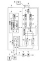
- FIG. 1 is an overall configuration diagram of a wireless relay system according to the first embodiment.
- FIG. 2 is an internal configuration diagram of the slave unit.
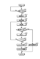
- FIG. 3 is a flowchart of a return process executed by the control unit when an abnormality of the communication unit is detected.
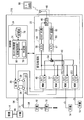
- FIG. 4 is an overall configuration diagram of a wireless relay system according to the second embodiment.
- FIG. 5 is an internal configuration diagram of the slave unit according to the second embodiment.
- the radio relay system 10 is a system generally called a repeater or a distributed antenna system (DAS).
- the radio relay system 10 includes a base unit (Master Unit: MU for short) 14 connected by relaying a radio signal from the base station 12 via a coaxial cable or an optical fiber, and a plurality of Remote Units (Remote Unit: abbreviated).
- RU Remote Unit
- RU 18 relays the communication by distributing it, and is installed in a closed space (for example, a building, underground mall, etc.) where radio signals do not reach and is connected to the parent unit (Remote Unit: RU for short)
- This is a system that relays communication via the network 18 and realizes the elimination of the insensitive zone of the mobile communication carrier and the expansion of the communication area.
- the first embodiment is an embodiment when the wireless relay system 10 is installed in a tunnel of a transportation facility such as a railway or a highway as an example of a closed space where a radio signal does not reach.
- a transportation facility such as a railway or a highway
- a radio relay system 10 when a failure occurs in an apparatus installed in an indoor space such as a general building or underground mall, a person can easily enter the installation location and perform repairs.
- the radio relay system 10 is installed in a tunnel such as a transportation facility (especially a high-speed Shinkansen), stop the operation for safety in order for people to enter the tunnel and perform repairs. It is necessary to repair (after the road is closed). For this reason, it cannot be repaired unless it waits until the night etc. when operation was completed.
- FIG. 1 is an overall configuration diagram of a wireless relay system 10 according to the first embodiment.
- the wireless relay system 10 includes a base station 12, a parent device 14, a plurality of child devices 18 serially installed inside a tunnel 92 and the like, and a monitoring device 16.
- the base station 12 is connected to a mobile phone network and is installed outside the tunnel 92.
- the base unit 14 is connected to the base station 12 by an optical fiber or a coaxial cable. Base unit 14 transmits and receives information to and from base station 12 by wired communication.
- the base unit 14 is installed outside the tunnel 92, for example, but the installation location is not particularly limited.
- the monitoring device 16 monitors the wireless relay system 10 and detects an abnormal state or the like.
- the monitoring device 16 has a computer or the like.
- the plurality of slave units 18 are directly or indirectly connected to the master unit 14.
- the plurality of slave units 18 are serially (ie, serially) connected to the lower side of the communication path with respect to the master unit 14 by the optical fiber 94.
- the highest rank slave unit 18 is connected to the master unit 14 by an optical fiber 94.
- the slave devices 18 other than the highest slave device 18 are serially connected to each other by an optical fiber 94.
- the child device 18 is connected to the upper child device 18 or the parent device 14 and to the lower child device 18 in the communication path.
- mobile_unit 18 functions as a radio relay apparatus which relays communication with the subunit
- the plurality of slave units 18 are installed at a plurality of different locations inside the tunnel 92. Thereby, the plurality of slave units 18 realizes communication in the entire area inside the tunnel 92.
- the wireless relay system 10 implements a non-sensing zone countermeasure and a communication area expansion by the plurality of slave units 18.
- Each cordless handset 18 transmits and receives information to and from a terminal 90 such as a mobile phone and a smartphone by wireless communication.
- FIG. 2 is an internal configuration diagram of the slave unit 18. As shown in FIG. 2, each of the plurality of slave units 18 includes an optical switch 20 that is an example of a switching unit, a communication unit 22, and a control unit 24.
- the optical switch 20 has four terminals 26, 28, 30 and 32, and switches the connection of these four terminals 26, 28, 30 and 32.
- Terminal 26 is connected to host device 18 or parent device 14 on the upper side.
- the terminal 28 is connected to the slave unit 18 on the lower side.
- the terminals 30 and 32 are connected to the communication unit 22.
- the optical switch 20 In the normal state in which the communication unit 22 can communicate with the terminal 90, the optical switch 20 connects the terminal 26 and the terminal 30 and connects the terminal 28 and the terminal 32 (hereinafter, referred to as a solid line in FIG. 2). Normal connection). Thereby, in the normal connection, the optical switch 20 connects the slave unit 18 or the master unit 14 on the upper side of the communication path and the slave unit 18 on the lower side of the communication path via the communication unit 22.
- the optical switch 20 is indicated by a dotted line in FIG. 2 in an abnormal state in which the communication unit 22 cannot communicate with the terminal 90 and an abnormal state in which the power to the slave unit 18 is not turned on or the power supply device is not turned on.
- the terminal 26 and the terminal 28 are connected to each other.
- the terminals 30 and 32 are not connected to the other terminals 26 and 28.
- the optical switch 20 connects the slave unit 18 or the master unit 14 on the upper side of the communication path and the slave unit 18 on the lower side of the communication path without using the communication unit 22 (hereinafter, bypass connection). . Therefore, the communication unit 22 is not connected to the communication path and is not involved in communication in the bypass connection.
- the optical switch 20 switches between normal connection and bypass connection based on the control of the control unit 24.
- the communication unit 22 performs processing such as conversion of communication signals to be transmitted / received, and transmits / receives signals to / from other slave units 18, the terminal 90, and the like.
- the communication unit 22 is connected to the optical switch 20.
- the communication unit 22 includes a higher-order photoelectric conversion unit 40, a signal processing unit 42, a transmission unit 44, a duplexer 46, an antenna 48, a reception unit 50, and a lower-order photoelectric conversion unit 52.
- the upper photoelectric conversion unit 40 is connected between the terminal 30 of the optical switch 20 and the signal processing unit 42.
- the high-order photoelectric conversion unit 40 converts the optical signal input from the high-order slave unit 18 or the master unit 14 via the terminal 26 and the terminal 30 of the optical switch 20 into an electrical signal.
- the upper photoelectric conversion unit 40 outputs the converted electrical signal to the signal processing unit 42. Further, the upper photoelectric conversion unit 40 converts the electric signal input from the signal processing unit 42 into an optical signal.
- the high-order photoelectric conversion unit 40 outputs the converted optical signal to the high-order slave unit 18 or the master unit 14 via the terminal 30 and the terminal 26 of the optical switch 20.
- the signal processing unit 42 is connected to the upper photoelectric conversion unit 40, the transmission unit 44, the lower photoelectric conversion unit 52, and the reception unit 50.
- the signal processing unit 42 outputs the electrical signal input from the upper photoelectric conversion unit 40 to the transmission unit 44 and the lower photoelectric conversion unit 52.
- the signal processing unit 42 includes an adder 54.
- the signal processing unit 42 adds, that is, multiplexes, and outputs the electrical signals input from the receiving unit 50 and the lower photoelectric conversion unit 52 to the upper photoelectric conversion unit 40.
- the transmission unit 44 is connected between the signal processing unit 42 and the duplexer 46.
- the transmission unit 44 includes a D / A conversion unit 56 and an analog circuit 58.
- the D / A conversion unit 56 converts the digital electrical signal output from the signal processing unit 42 into an analog electrical signal.
- the analog circuit 58 converts the baseband analog electrical signal output from the D / A converter 56 into a radio frequency electrical signal and amplifies it, and then transmits it to the terminal 90 via the duplexer 46 and the antenna 48.
- the duplexer 46 is connected to the transmission unit 44, the reception unit 50, and the antenna 48.
- the duplexer 46 outputs the electrical signal output from the transmission unit 44 to the antenna 48 without outputting it to the reception unit 50.
- the duplexer 46 outputs the electrical signal received by the antenna 48 from the external terminal 90 to the receiving unit 50 without outputting it to the transmitting unit 44.
- the antenna 48 transmits the electrical signal input from the transmission unit 44 via the duplexer 46 to the terminal 90.
- the antenna 48 receives the electrical signal transmitted by the external terminal 90 and outputs it to the duplexer 46.
- the receiving unit 50 is connected between the signal processing unit 42 and the duplexer 46.
- the receiving unit 50 includes an analog circuit 60 and an A / D conversion unit 62.
- the analog circuit 60 amplifies the radio frequency electrical signal received from the terminal 90 via the antenna 48 and converts it into a baseband electrical signal.
- the A / D converter 62 converts the baseband analog electrical signal output from the analog circuit 60 into a digital electrical signal and outputs the digital electrical signal to the signal processor 42.
- the lower photoelectric conversion unit 52 is connected between the terminal 32 of the optical switch 20 and the signal processing unit 42.
- the lower photoelectric conversion unit 52 converts the electrical signal input from the signal processing unit 42 into an optical signal.
- the lower photoelectric conversion unit 52 outputs the converted optical signal to the lower slave unit 18 via the terminal 28 and the terminal 32 of the optical switch 20.
- the lower photoelectric conversion unit 52 converts the optical signal input from the lower slave unit 18 into an electrical signal via the terminal 28 and the terminal 32 of the optical switch 20.
- the lower-order photoelectric conversion unit 52 outputs the converted electric signal to the signal processing unit 42.
- the control unit 24 governs overall control of the slave unit 18.
- An example of the control unit 24 is a computer.
- the control unit 24 includes an optical switch control unit 74 and a storage unit 76.
- the optical switch control unit 74 includes a processing unit such as a CPU (Central Processing Unit).
- the optical switch control unit 74 includes a determination unit 78 and a switching control unit 80.
- the optical switch control unit 74 functions as the switching control unit 80 and the determination unit 78 by reading a program stored in the storage unit 76.
- a part or all of the determination unit 78 and the switching control unit 80 may be configured by hardware such as a circuit.
- the determination unit 78 controls the communication unit 22 of the slave unit 18.
- the determination unit 78 determines whether the communication unit 22 can communicate normally or cannot communicate.
- the determination unit 78 outputs a signal indicating an abnormality to the switching control unit 80 to switch the optical switch 20 to the bypass connection.
- the abnormality of the communication unit 22 and the control unit 24 determined by the determination unit 78 includes power supply abnormality and communication abnormality.
- the power supply abnormality includes abnormality of the power supply that supplies power to the communication unit 22 and power supply abnormality. If the control unit 24 does not operate due to power failure, the optical switch 20 is autonomously bypassed regardless of the control of the control unit 24.
- the communication abnormality includes an abnormality of a clock supplied to the communication unit 22 for communication.
- the determination unit 78 restarts the handset 18 including the communication unit 22 and the control unit 24 after the switching control unit 80 switches the optical switch 20 from the bypass connection to the normal connection, It is determined again whether the communication unit 22 is normal or abnormal. For example, after determining the abnormality, the determination unit 78 restarts the slave unit 18 at a predetermined return time.
- the determination unit 78 includes any or all of the higher-order photoelectric conversion unit 40, the signal processing unit 42, the transmission unit 44, the duplexer 46, the reception unit 50, and the lower-order photoelectric conversion unit 52 of the communication unit 22 and the control unit 24. Restart. If the determining unit 78 determines that the restarted communication unit 22 is normal, the determining unit 78 maintains the normal connection.
- the switching control unit 80 controls the optical switch 20.
- the switching control unit 80 connects the terminal 26 and the terminal 30 and connects the terminal 28 and the terminal 28 as indicated by a solid line in FIG. 2 in a state where the communication unit 22 is determined to be normal by the determination unit 78. And the terminal 32 are connected, and the optical switch 20 is normally connected.
- the determination unit 78 determines that the communication unit 22 is incapable of communication
- the switching control unit 80 connects the terminal 26 and the terminal 28 and connects the optical switch 20 to the bypass connection as shown by a dotted line in FIG. Switch.
- the switching control unit 80 switches the optical switch 20 from the bypass connection to the normal connection when the return time comes after the communication unit 22 has determined that the determination unit 78 has determined that there is an abnormality and switched to the bypass connection. .
- the storage unit 76 includes a volatile RAM (Random Access Memory), a nonvolatile flash memory, and the like.
- the storage unit 76 stores a program read by the optical switch control unit 74, parameters necessary for executing the program, and the like.
- the switching control unit 80 of the optical switch control unit 74 connects the terminal 26 and the terminal 30 of the optical switch 20 as shown by the solid line in FIG. Connected.
- the optical switch 20 outputs an electric signal from the terminal 30 to the upper photoelectric conversion unit 40 when an electrical signal is input to the terminal 26 from the upper slave unit 18 or the parent unit 14.
- the upper photoelectric conversion unit 40 outputs an electrical signal to the transmission unit 44 and the lower photoelectric conversion unit 52 via the signal processing unit 42.
- the transmission unit 44 converts an analog baseband electrical signal into a digital radio frequency, and then transmits the converted signal to the terminal 90 via the duplexer 46 and the antenna 48.
- the lower photoelectric conversion unit 52 converts the electrical signal input from the upper photoelectric conversion unit 40 into an optical signal via the signal processing unit 42 and outputs the optical signal to the terminal 32 of the optical switch 20.
- the optical switch 20 outputs the optical signal input to the terminal 32 from the terminal 28 to the lower slave unit 18.
- the operation of the slave unit 18 when the slave unit 18 receives an electrical signal from the terminal 90 and when an optical signal is input from the subordinate slave unit 18 will be described.
- the antenna 48 receives an electrical signal from the terminal 90
- the electrical signal is output to the receiving unit 50 via the duplexer 46.
- the receiving unit 50 converts the radio frequency analog electrical signal into a digital baseband electrical signal and outputs the digital baseband electrical signal to the adder 54 of the signal processing unit 42.
- the optical switch 20 outputs the optical signal input from the lower slave unit 18 to the terminal 28 to the lower photoelectric conversion unit 52 via the terminal 32.
- the lower photoelectric conversion unit 52 converts the optical signal into an electrical signal and outputs the electrical signal to the adder 54 of the signal processing unit 42.
- the adder 54 of the signal processing unit 42 adds or multiplexes the electric signal input from the receiving unit 50 and the electric signal input from the lower photoelectric conversion unit 52, and outputs the multiplexed signal to the upper photoelectric conversion unit 40.
- the upper photoelectric conversion unit 40 converts the multiplexed electric signal into an optical signal and outputs the optical signal to the terminal 30 of the optical switch 20.
- the optical switch 20 outputs the electrical signal input to the terminal 30 from the terminal 26 to the upper slave unit 18 or the master unit 14.
- the switching control unit 80 of the optical switch control unit 74 bypass-connects the terminal 26 and the terminal 28 of the optical switch 20 as indicated by a dotted line in FIG.
- the slave unit 18 transmits the optical signal input from the upper slave unit 18 or the master unit 14 to the terminal 26 of the optical switch 20 from the terminal 28 to the lower slave unit 18 without passing through the communication unit 22. Is output.
- the slave unit 18 outputs the optical signal input from the lower slave unit 18 to the terminal 28 of the optical switch 20 from the terminal 26 to the upper slave unit 18 or the master unit 14 without passing through the communication unit 22.
- the slave unit 18 in an abnormal state outputs the input optical signal without performing any conversion and processing.
- FIG. 3 is a flowchart of a return process executed by the optical switch control unit 74 when the communication unit 22 is determined to be abnormal. With reference to FIG. 3, the return process in an abnormal state is demonstrated.
- the return process in the abnormal state of the communication unit 22 starts from a state where the communication unit 22 is determined to be abnormal by the determination unit 78 and switched to the bypass connection indicated by the dotted line in FIG.
- the determination unit 78 determines whether it is a return time (S100).
- the return time is preset and stored in the storage unit 76. For example, the return time is set to a midnight time such as 2:00 am when the communication between the handset 18 and the terminal 90 is low.
- the determination unit 78 waits until the return time is reached (S100: No).
- the determination unit 78 When determining that the return time has come (S100: Yes), the determination unit 78 outputs a return instruction to the switching control unit 80 (S110). When acquiring the return instruction, the switching control unit 80 switches the optical switch 20 from the bypass connection to the normal connection (S120). The determination part 78 restarts the subunit
- the determination unit 78 determines whether the communication unit 22 is normal or abnormal while the slave unit 18 is restarted (S140). If the determination unit 78 determines that the communication unit 22 is in a normal state in which normal communication is possible (S140: Yes), the normal connection of the optical switch 20 is maintained (S145), and the return process is terminated. As a result, the handset 18 returns to normal communication by the communication unit 22.
- the determination unit 78 determines that the communication unit 22 is in an abnormal state where normal communication is not possible (S140: No)
- the determination count N is incremented by 1 (S150).
- the determination count N is set to an initial value (for example, 0) and stored in the storage unit 76 when the return process is started.
- the determination unit 78 determines whether or not the determination count N is the specified number SN (S160).
- the specified number of times SN is set in advance and stored in the storage unit 76. An example of the prescribed number SN is several times.
- determining unit 78 determines that determination count N is not the prescribed number of times SN (S160: No)
- it restarts slave unit 18 and determines whether communication unit 22 is normal or not.
- the determination unit 78 repeats steps S130 to S150 unless the communication unit 22 determines normal. Thereafter, when the determination unit 78 repeats steps S130 to S150 and determines that the determination count N has reached the specified number of times SN (S160: Yes), it outputs a bypass instruction to the switching control unit 80 (S170).
- the switching control unit 80 When acquiring the bypass instruction, the switching control unit 80 returns the optical switch 20 to the bypass connection (S180). In other words, if the determination unit 78 does not determine that the communication unit 22 is normal even after the communication unit 22 has been restarted SN the specified number of times, the switching control unit 80 switches the optical switch 20 to the bypass connection. As a result, the optical switch control unit 74 ends the return process without returning the communication unit 22 of the slave unit 18.
- the determination unit 78 restarts the slave unit 18 determined to be abnormal, and the switching control unit 80 switches the optical switch 20 to the normal connection. 78 again determines whether the communication unit 22 is normal or abnormal. As a result, the determination unit 78 can correctly determine the child device 18 that operates normally only by a temporary failure by restarting the child device 18, so that the communication by the child device 18 can be easily restored. Can be made. In addition, the control unit 24 can restore the normal communication unit 22 that has only temporarily failed without repair by an operator or the like.
- the control unit 24 of each slave unit 18 is easy and quick. To normal communication. As a result, the control unit 24 of each slave unit 18 can omit the application for the work in the tunnel 92 necessary for resuming the communication and reduce the time required for the work.
- the slave unit 18 is restarted at the return time set in advance by the determination unit 78.
- the control part 24 can perform restart of the subunit
- the control part 24 can implement
- the switching control unit 80 When the slave unit 18 determines that the communication unit 22 restarted by the determination unit 78 is abnormal, the switching control unit 80 returns the optical switch 20 to the bypass connection. Thereby, the control part 24 can return the low-order subunit
- the determination unit 78 restarts the communication unit 22 a predetermined number of times and determines whether or not the communication unit 22 is normal. Therefore, the determination accuracy of the normal communication unit 22 can be improved.
- the wireless relay system as a countermeasure against undetection of the cellular phone network has been described. However, it can also be used as a countermeasure against undetection of a public wireless LAN system connected to the Internet network. In this case, the same effect can be obtained by connecting the base unit 14 to the Internet network (not shown) instead of the base station 12.
- FIG. 4 is an overall configuration diagram of the wireless relay system 210 according to the second embodiment.
- the wireless relay system 210 shown in FIG. 4 is a wireless relay system in which the connection form of the slave unit 218 is not a serial connection, but a specific slave unit 218 has a connection form by branching a communication path.
- FIG. 5 is an internal configuration diagram of the slave unit 218 according to the second embodiment. As shown in FIG. 5, the slave unit 218 further includes a second lower-level photoelectric conversion unit 252 and a third lower-level photoelectric conversion unit 253.
- the second lower photoelectric conversion unit 252 is connected to the upper photoelectric conversion unit 40, the adder 54 of the signal processing unit 42, and the lower slave unit 18.
- the second lower photoelectric conversion unit 252 converts the electrical signal input from the upper photoelectric conversion unit 40 into an optical signal and outputs the optical signal to the lower slave unit 18.
- the second lower photoelectric conversion unit 252 converts the optical signal input from the lower slave unit 18 into an electrical signal and outputs the electrical signal to the adder 54 of the signal processing unit 42.
- the third lower photoelectric conversion unit 253 is connected to the upper photoelectric conversion unit 40, the adder 54 of the signal processing unit 42, and the lower slave unit 18.
- the 3rd lower side photoelectric conversion part 253 is connected with the subunit
- FIG. The third lower photoelectric conversion unit 253 converts the electrical signal input from the upper photoelectric conversion unit 40 into an optical signal and outputs the optical signal to the lower slave unit 18.
- the third lower photoelectric conversion unit 253 converts the optical signal input from the lower slave unit 18 into an electrical signal and outputs the electrical signal to the adder 54 of the signal processing unit 42.
- the adder 54 of the signal processing unit 42 adds the three electrical signals output from the lower photoelectric conversion unit 52, the second lower photoelectric conversion unit 252, and the third lower photoelectric conversion unit 253. Then, the data is output to the upper photoelectric conversion unit 40.
- the slave units 18 are connected to each other by the optical fiber 94.
- the slave units 18 may be connected to each other by an electric wire, and the slave units 18 may transmit and receive information by electrical communication.
- the wireless relay system 10 in which the slave unit 18 is installed in the tunnel 92 is taken as an example, but the present invention is not limited to this.
- the above-described embodiment may be applied to the wireless relay system 10 in which the handset 18 is installed indoors and in an underground mall.
- the optical switch control unit 74 starts the return process at a predetermined time.
- the present invention is not limited to this, and the return process may be started at a predetermined timing.
- the optical switch control unit 74 may determine that the optical switch 20 is in an abnormal state and start the return process after a predetermined time has elapsed since the optical switch 20 is bypassed.
- the optical switch control unit 74 repeats the specified number of times SN and restart, but is not limited thereto.
- the optical switch control unit 74 may restart only once and determine whether it is normal.
- the slave unit 18 is restarted, but only the communication unit 22 may be restarted.
- step S120 and the process of step S130 may be switched in order. That is, after the determination unit 78 restarts the communication unit 22, the switching control unit 80 may switch the optical switch 20 from the bypass connection to the normal connection. Even in this case, the determination unit 78 determines whether the communication unit 22 is normal or abnormal after the switching control unit 80 switches the optical switch 20 to the normal connection.
- control unit 24 is provided in the slave unit 18
- a part or all of the control unit 24 may be provided in other equipment such as the base unit 14 or the base station 12.
- the communication unit 22 includes the upper photoelectric conversion unit 40, the signal processing unit 42, the transmission unit 44, the duplexer 46, the antenna 48, the reception unit 50, and the lower photoelectric conversion unit 52.
- the configuration of the communication unit 22 may be changed as appropriate.
- the communication unit 22 may be configured to include a part of the upper photoelectric conversion unit 40, the signal processing unit 42, the transmission unit 44, the duplexer 46, the antenna 48, the reception unit 50, and the lower photoelectric conversion unit 52. Good.
- the wireless relay system as a countermeasure against undetection of the cellular phone network has been described, but it can also be used as a countermeasure against undetection of a public wireless LAN system connected to the Internet network.
- the base unit 14 can achieve the same effect by connecting to the Internet network (not shown) instead of the base station 12.
Landscapes
- Engineering & Computer Science (AREA)
- Computer Networks & Wireless Communication (AREA)
- Signal Processing (AREA)
- Physics & Mathematics (AREA)
- Electromagnetism (AREA)
- Mobile Radio Communication Systems (AREA)
- Optical Communication System (AREA)
Abstract
一時的な故障の子機を復帰させて通信させる。無線中継システムは、親機と、複数の子機とを備える。複数の子機は、親機よりも通信経路の下位側に接続されている。複数の子機のそれぞれは、切替部と、通信部と、判定部と、切替制御部とを備える。切替部は、親機または上位側の子機と下位側の子機とを通信部を介して接続する通常接続と、親機または上位側の子機と下位側の子機とを通信部を介さずに接続するバイパス接続とに切り替える。通信部は、送受信する信号を処理して通信する。判定部は、通信部が正常か異常かを判定する。切替制御部は、判定部が通信部を異常と判定すると、切替部をバイパス接続に切り替える。判定部は、切替部を通常接続に切り替えた後、通信部を再起動させ、通信部が正常か異常かを判定する。
Description
本発明の実施形態は、無線中継システム、無線中継システムの子機、及び、無線中継システムの復帰方法に関する。
モバイル通信事業者の不感知対策及び通信エリア拡張として、基地局からの無線信号を同軸ケーブルまたは光ファイバを介して中継して接続された親機と、親機と接続された子機とを備える無線中継システムが知られている。このような無線中継システムでは、互いに接続され、無線中継装置としても機能する複数の子機を無線信号の届かない閉空間に設置することで不感知帯の解消、通信エリア拡張を実現する。
このような無線中継システムでは、シリアルに接続された子機のいずれかが故障すると、当該子機の下位側に接続された子機が正常であっても端末と通信できない。そこで、故障した子機をバイパスして、故障した子機の下位側の子機と、故障した子機の上位側の子機または親機とを接続する技術が知られている。
しかしながら、故障した子機が一時的な故障であっても、当該子機がバイパスされているので作業者に修理されるまで通信できないといった課題がある。
本発明の実施形態は、上記に鑑みてなされたものであって、一時的な故障の子機を復帰させて通信させることができる無線中継システムを提供することを目的とする。
本発明の実施形態の無線中継システムは、親機と、複数の子機とを備える。複数の子機は、親機よりも通信経路の下位側に接続されている。複数の子機のそれぞれは、切替部と、通信部と、判定部と、切替制御部とを備える。切替部は、親機または上位側の子機と下位側の子機とを通信部を介して接続する通常接続と、親機または上位側の子機と下位側の子機とを通信部を介さずに接続するバイパス接続とに切り替える。通信部は、送受信する信号を処理して通信する。判定部は、通信部が正常か異常かを判定する。切替制御部は、判定部が通信部を異常と判定すると、切替部をバイパス接続に切り替える。判定部は、切替制御部が切替部をバイパス接続から通常接続に切り替えた後、通信部を再起動させ、通信部が正常か異常かを判定する。
以下の例示的な実施形態や変形例には、同様の構成要素が含まれている。よって、以下では、同様の構成要素には共通の符号が付されるとともに、重複する説明が部分的に省略される。実施形態や変形例に含まれる部分は、他の実施形態や変形例の対応する部分と置き換えて構成されることができる。また、実施形態や変形例に含まれる部分の構成や位置等は、特に言及しない限りは、他の実施形態や変形例と同様である。
無線中継システム10は、一般に、リピータとか、分散アンテナシステム(DAS:Distributed Antenna System)とも称されるシステムである。無線中継システム10は、基地局12からの無線信号を同軸ケーブルまたは光ファイバを介して中継して接続された親機(Master Unit:略してMU)14と、複数の子機(Remote Unit:略してRU)18に分配することによって通信を中継して、無線信号の届かない閉空間(例えば、ビル、地下街等)に設置され、親機と接続された子機(Remote Unit:略してRU)18を介して通信を中継するもので、モバイル通信事業者の不感知帯の解消、通信エリア拡張を実現するシステムである。
<第1実施形態>
第1実施形態は、無線中継システム10を、無線信号の届かない閉空間の一例として鉄道や高速道路等の交通機関のトンネルに設置された場合の実施形態である。本実施形態の無線中継システム10では、一般的なビル、地下街等の屋内空間に設置される装置に故障が発生した場合、人が容易に設置場所に入り込んで修理を行うことができる。これに対し、交通機関等のトンネルに無線中継システム10が設置されている場合(特に、速度の速い新幹線等)では、人がトンネルに入り込んで修理を行うためには、安全上運行を止めて(道路の場合は通行止めの処置を行ってから)修理を行う必要がある。このため、運行が終了した夜間等まで待たないと、修理を行うことができない。
第1実施形態は、無線中継システム10を、無線信号の届かない閉空間の一例として鉄道や高速道路等の交通機関のトンネルに設置された場合の実施形態である。本実施形態の無線中継システム10では、一般的なビル、地下街等の屋内空間に設置される装置に故障が発生した場合、人が容易に設置場所に入り込んで修理を行うことができる。これに対し、交通機関等のトンネルに無線中継システム10が設置されている場合(特に、速度の速い新幹線等)では、人がトンネルに入り込んで修理を行うためには、安全上運行を止めて(道路の場合は通行止めの処置を行ってから)修理を行う必要がある。このため、運行が終了した夜間等まで待たないと、修理を行うことができない。
図1は、第1実施形態にかかる無線中継システム10の全体構成図である。図1に示すように、無線中継システム10は、基地局12と、親機14と、トンネル92等の内部にシリアルに設置された複数の子機18と、監視装置16とを備える。
基地局12は、携帯電話網に接続されるもので、トンネル92の外部に設置される。
親機14は、基地局12と光ファイバまたは同軸ケーブル等によって接続されている。親機14は、基地局12と有線通信によって、情報を送受信する。親機14は、例えば、トンネル92の外部等に設置されるが、特に設置場所は限定されるものではない。
監視装置16は、無線中継システム10を監視して、異常状態等を検出する。監視装置16は、コンピュータ等を有する。
複数の子機18は、直接的または間接的に親機14と接続される。複数の子機18は、光ファイバ94によって親機14よりも通信経路の下位側でシリアル(即ち、直列)に接続されている。シリアルに接続された子機18のうち最も上位の子機18は、親機14と光ファイバ94によって接続されている。最も上位の子機18以外の子機18は、互いに光ファイバ94でシリアルに接続されている。換言すれば、子機18は、通信経路において、上位側の子機18または親機14と接続されるとともに、下位側の子機18と接続されている。これにより、子機18は、上位側の子機18と下位側の子機18との通信を中継する無線中継装置として機能する。複数の子機18は、トンネル92の内部の異なる複数の場所に設置される。これにより、複数の子機18が、トンネル92の内部の全域での通信を実現する。この結果、無線中継システム10は、複数の子機18によって、不感知帯対策及び通信エリア拡張を実現する。各子機18は、携帯電話及びスマートフォン等の端末90と無線通信によって情報を送受信する。
図2は、子機18の内部構成図である。図2に示すように、複数の子機18のそれぞれは、切替部の一例である光スイッチ20と、通信部22と、制御部24とを備える。
光スイッチ20は、4つの端子26、28、30、32を有し、これら4つの端子26、28、30、32の接続を切り替える。端子26は、上位側の子機18または親機14と接続される。端子28は、下位側の子機18と接続される。端子30及び端子32は、通信部22と接続される。
光スイッチ20は、通信部22が端末90と通信可能な正常状態では、図2に実線で示すように、端子26と端子30とを接続するとともに、端子28と端子32とを接続(以下、通常接続)する。これにより、光スイッチ20は、通常接続では、通信経路の上位側の子機18または親機14と、通信経路の下位側の子機18とを、通信部22を介して接続する。
光スイッチ20は、通信部22が端末90と通信不可能な異常状態、及び、子機18への電源未投入または電源装置異常等の電源が入らない異常状態では、図2に点線で示すように、端子26と端子28とを接続する。端子30と端子32は、他の端子26及び端子28に接続されない。これにより、光スイッチ20は、通信経路の上位側の子機18または親機14と、通信経路の下位側の子機18とを、通信部22を介さずに接続(以下、バイパス接続)する。従って、通信部22は、バイパス接続では、通信経路に接続されず、通信に関与しない。光スイッチ20は、制御部24の制御に基づいて、通常接続と、バイパス接続とを切り替える。
通信部22は、送受信する通信の信号を変換等の処理を実行して、他の子機18及び端末90等と信号を送受信する。通信部22は、光スイッチ20と接続されている。通信部22は、上位側光電変換部40と、信号処理部42と、送信部44と、デュプレクサ46と、アンテナ48と、受信部50と、下位側光電変換部52とを備える。
上位側光電変換部40は、光スイッチ20の端子30と信号処理部42との間に接続されている。上位側光電変換部40は、光スイッチ20の端子26及び端子30を介して、上位の子機18または親機14から入力された光信号を電気信号に変換する。上位側光電変換部40は、変換した電気信号を信号処理部42へ出力する。また、上位側光電変換部40は、信号処理部42から入力された電気信号を光信号に変換する。上位側光電変換部40は、光スイッチ20の端子30及び端子26を介して、変換した光信号を上位の子機18または親機14へ出力する。
信号処理部42は、上位側光電変換部40、送信部44、下位側光電変換部52、及び、受信部50と接続されている。信号処理部42は、上位側光電変換部40から入力された電気信号を送信部44及び下位側光電変換部52へ出力する。信号処理部42は、加算器54を有する。信号処理部42は、受信部50及び下位側光電変換部52から入力された電気信号を加算器54によって加算、即ち、多重化して上位側光電変換部40へ出力する。
送信部44は、信号処理部42とデュプレクサ46との間に接続されている。送信部44は、D/A変換部56と、アナログ回路58とを有する。送信部44では、D/A変換部56が、信号処理部42が出力したデジタルの電気信号をアナログの電気信号に変換する。アナログ回路58は、D/A変換部56が出力したベースバンドのアナログの電気信号を無線周波数の電気信号に変換して増幅した後、デュプレクサ46及びアンテナ48を介して、端末90へ送信する。
デュプレクサ46は、送信部44、受信部50、及び、アンテナ48と接続されている。デュプレクサ46は、送信部44が出力した電気信号を受信部50へ出力することなく、アンテナ48へ出力する。デュプレクサ46は、外部の端末90からアンテナ48が受信した電気信号を、送信部44へ出力することなく、受信部50へと出力する。
アンテナ48は、デュプレクサ46を介して送信部44から入力した電気信号を端末90へと送信する。アンテナ48は、外部の端末90が送信した電気信号を受信して、デュプレクサ46へと出力する。
受信部50は、信号処理部42とデュプレクサ46との間に接続されている。受信部50は、アナログ回路60と、A/D変換部62とを有する。受信部50では、アナログ回路60が、アンテナ48を介して端末90から受信した無線周波数の電気信号を増幅してベースバンドの電気信号に変換する。A/D変換部62は、アナログ回路60が出力したベースバンドのアナログの電気信号をデジタルの電気信号に変換して、信号処理部42へ出力する。
下位側光電変換部52は、光スイッチ20の端子32と信号処理部42との間に接続されている。下位側光電変換部52は、信号処理部42から入力された電気信号を光信号に変換する。下位側光電変換部52は、光スイッチ20の端子28及び端子32を介して、変換した光信号を下位の子機18へと出力する。また、下位側光電変換部52は、光スイッチ20の端子28及び端子32を介して、下位の子機18から入力された光信号を電気信号に変換する。下位側光電変換部52は、変換した電気信号を信号処理部42へ出力する。
制御部24は、子機18の制御全般を司る。制御部24の一例は、コンピュータである。制御部24は、光スイッチ制御部74と、記憶部76とを有する。
光スイッチ制御部74は、CPU(Central Processing Unit)等の演算処理装置を含む。光スイッチ制御部74は、判定部78と、切替制御部80とを備える。例えば、光スイッチ制御部74は、記憶部76に記憶されたプログラムを読み込むことによって、切替制御部80と、判定部78として機能する。尚、判定部78及び切替制御部80の一部または全てを回路等のハードウエアによって構成してもよい。
判定部78は、子機18の通信部22を制御する。判定部78は、通信部22が通信可能な正常か通信不可能な異常かを判定する。判定部78は、通信部22が異常と判定すると、切替制御部80に異常である旨の信号を出力して、光スイッチ20をバイパス接続に切り替えさせる。判定部78の判定する通信部22及び制御部24の異常は、電源異常及び通信異常を含む。電源異常は、通信部22に電力を供給する電源の異常、及び、電力の供給異常を含む。尚、制御部24が電源異常となり動作しない場合、光スイッチ20は制御部24の制御によらず自律的にバイパス接続となる。通信異常は、通信用に通信部22に供給されるクロックの異常を含む。また、判定部78は、異常と判定した後、切替制御部80が光スイッチ20をバイパス接続から通常接続に切り替えた後、通信部22及び制御部24を含む子機18を再起動させて、通信部22が正常か異常かを再度判定する。例えば、判定部78は、異常と判定した後、予め定められた復帰時刻に子機18を再起動させる。判定部78は、通信部22の上位側光電変換部40、信号処理部42、送信部44、デュプレクサ46、受信部50、及び、下位側光電変換部52のいずれかまたは全てと制御部24とを再起動させる。判定部78は、再起動させた通信部22が正常と判定すると、通常接続を維持させる。
切替制御部80は、光スイッチ20を制御する。例えば、切替制御部80は、通信部22が判定部78によって通信可能な正常と判定されている状態では、図2に実線で示すように、端子26と端子30とを接続させるとともに、端子28と端子32とを接続させて、光スイッチ20を通常接続とする。切替制御部80は、判定部78が通信部22を通信不可能な異常と判定すると、図2に点線で示すように、端子26と端子28とを接続させて、光スイッチ20をバイパス接続に切り替える。また、切替制御部80は、通信部22が判定部78によって異常と判定されることにより光スイッチ20をバイパス接続に切り替えた後、復帰時刻になると、バイパス接続から通常接続に光スイッチ20を切り替える。
記憶部76は、揮発性のRAM(Random Access Memory)、及び、不揮発性のフラッシュメモリ等を有する。記憶部76は、光スイッチ制御部74によって読み込まれるプログラム、及び、プログラムの実行に必要なパラメータ等を記憶する。
次に、通信部22が判定部78によって正常と判定されている状態における子機18の動作について説明する。
まず、通信部22が正常状態の子機18の動作を説明する。正常状態の子機18では、光スイッチ制御部74の切替制御部80は、図2に実線で示すように光スイッチ20の端子26と端子30とを接続するとともに、端子28と端子32とを接続させている。
上位の子機18または親機14から電気信号が入力された場合の子機18の動作について説明する。光スイッチ20は、上位の子機18または親機14から電気信号が端子26に入力されると、端子30から上位側光電変換部40へ出力する。上位側光電変換部40は、信号処理部42を介して、電気信号を送信部44及び下位側光電変換部52へ出力する。送信部44は、アナログのベースバンドの電気信号をデジタルの無線周波数に変換した後、デュプレクサ46及びアンテナ48を介して、端末90へと送信する。また、下位側光電変換部52は、信号処理部42を介して、上位側光電変換部40から入力された電気信号を光信号に変換して光スイッチ20の端子32へと出力する。光スイッチ20は、端子32に入力した光信号を端子28から下位の子機18へと出力する。
子機18が、端末90から電気信号を受信した場合、及び、下位の子機18から光信号が入力された場合の子機18の動作について説明する。アンテナ48が端末90から電気信号を受信すると、当該電気信号をデュプレクサ46を介して、受信部50へ出力する。受信部50は、無線周波数のアナログの電気信号をデジタルのベースバンドの電気信号に変換して、信号処理部42の加算器54へ出力する。光スイッチ20は、下位の子機18から端子28に入力された光信号を、端子32を介して、下位側光電変換部52へ出力する。下位側光電変換部52は、光信号を電気信号に変換して、信号処理部42の加算器54へ出力する。信号処理部42の加算器54は、受信部50から入力された電気信号及び下位側光電変換部52から入力された電気信号を加算、即ち多重化して上位側光電変換部40へ出力する。上位側光電変換部40は、多重化された電気信号を光信号に変換して、光スイッチ20の端子30へと出力する。光スイッチ20は、端子30に入力した電気信号を端子26から上位の子機18または親機14へと出力する。
次に、通信部22が異常状態の子機18の動作を説明する。通信部22が異常状態の子機18では、光スイッチ制御部74の切替制御部80は、図2に点線で示すように光スイッチ20の端子26と端子28とをバイパス接続させる。この状態では、子機18は、上位の子機18または親機14から光スイッチ20の端子26に入力した光信号を、通信部22を介すことなく、端子28から下位の子機18へと出力する。また、子機18は、下位の子機18から光スイッチ20の端子28に入力した光信号を、通信部22を介すことなく、端子26から上位の子機18または親機14へと出力する。換言すれば、異常状態の子機18は、入力する光信号に対して何も変換及び処理することなく出力する。
図3は、通信部22が異常と判定された場合に、光スイッチ制御部74が実行する復帰処理のフローチャートである。図3を参照して、異常状態における復帰処理について説明する。
通信部22の異常状態における復帰処理は、判定部78によって通信部22が異常と判定された場合に、図2に点線で示すバイパス接続に切り替えられた状態から開始する。復帰処理では、判定部78は、復帰時刻か否かを判定する(S100)。復帰時刻は、予め設定されて記憶部76に格納されている。例えば、復帰時刻は、子機18と端末90との通信が少ない午前2時等の深夜の時刻に設定される。判定部78は、復帰時刻となるまで待機する(S100:No)。
判定部78は、復帰時刻になったと判定すると(S100:Yes)、切替制御部80に復帰指示を出力する(S110)。切替制御部80は、復帰指示を取得すると、光スイッチ20をバイパス接続から通常接続に切り替える(S120)。判定部78は、復帰指示を出力した後、子機18を再起動させる(S130)。
判定部78は、子機18を再起動させた状態で、通信部22が正常か異常かを判定する(S140)。判定部78は、通信部22が通常の通信ができる正常状態と判定すると(S140:Yes)、光スイッチ20の通常接続を維持させて(S145)、復帰処理を終了する。この結果、子機18は、通信部22による通常の通信に復帰する。
一方、判定部78は、通信部22が通常の通信ができない異常状態と判定すると(S140:No)、判定カウントNを1インクリメントする(S150)。判定カウントNは、復帰処理が開始されたときは初期値(例えば、0)に設定されて記憶部76に格納されている。
判定部78は、判定カウントNが規定回数SNか否かを判定する(S160)。規定回数SNは、予め設定されて記憶部76に格納されている。規定回数SNの一例は、数回である。判定部78は、判定カウントNが規定回数SNでないと判定すると(S160:No)、子機18を再起動して、通信部22が正常か否かを判定する。判定部78は、通信部22を正常と判定しない限り、ステップS130からS150を繰り返す。この後、判定部78は、ステップS130からS150を繰り返して、判定カウントNが規定回数SNになったと判定すると(S160:Yes)、切替制御部80へバイパス指示を出力する(S170)。切替制御部80は、バイパス指示を取得すると、光スイッチ20をバイパス接続に戻す(S180)。換言すれば、判定部78は通信部22を規定回数SN再起動しても通信部22を正常と判定しなかった場合、切替制御部80は光スイッチ20をバイパス接続に切り替える。この結果、光スイッチ制御部74は、子機18の通信部22を復帰させることなく、復帰処理を終了する。
上述したように、無線中継システム10の子機18では、判定部78が異常と判定した子機18を再起動させて、切替制御部80が光スイッチ20を通常接続に切り替えた後、判定部78は、通信部22が正常か異常かを再度判定する。これにより、判定部78は、子機18を再起動させることによって、一時的に故障しただけで正常に動作する子機18を正しく判定することができるので、子機18による通信を容易に復帰させることができる。また、制御部24は、一時的に故障しただけの正常な通信部22を作業者等の修理によらず復帰させることができる。従って、無線中継システム10の子機18が、トンネル92等のように人が入り込んで修理することが困難な場所に設置されていても、それぞれの子機18の制御部24は、容易かつ迅速に通常の通信に復帰させることができる。この結果、それぞれの子機18の制御部24は、通信の再開に必要なトンネル92での作業の申請等を省略するとともに、作業に必要な時間を低減できる。
子機18では、判定部78が予め設定した復帰時刻に子機18の再起動を実行する。これにより、制御部24は、子機18が通信をほとんど行わない夜間等に子機18の再起動を実行できる。これにより、制御部24は、通信部22を接続することによる下位の子機18の通信への影響を低減しつつ、通信部22の復帰を実現できる。
子機18では、判定部78が再起動させた通信部22を異常と判定すると、切替制御部80が光スイッチ20をバイパス接続に戻す。これにより、制御部24は、通信部22が一時的な故障でない場合、下位の子機18を通信可能な状態に戻すことができる。
子機18では、判定部78が通信部22を規定回数SN再起動させて、通信部22が正常か否かを判定するので、正常な通信部22の判定精度を向上させることができる。
上述の実施形態では、携帯電話網の不感知対策としての無線中継システムついて、説明したが、インターネット網に接続された公衆無線LANシステムの不感知対策としても利用できる。この場合、親機14は基地局12ではなく、図示していないインターネット網に接続することで、同様の効果を奏することができる。
<第2実施形態>
図4は、第2実施形態にかかる無線中継システム210の全体構成図である。図4に示す無線中継システム210では、子機218の接続形態がシリアル接続でなく、特定の子機218で、通信経路を分岐して接続形態を有する無線中継システムである。
図4は、第2実施形態にかかる無線中継システム210の全体構成図である。図4に示す無線中継システム210では、子機218の接続形態がシリアル接続でなく、特定の子機218で、通信経路を分岐して接続形態を有する無線中継システムである。
図5は、第2実施形態にかかる子機218の内部構成図である。図5に示すように、子機218は、第2下位側光電変換部252と、第3下位側光電変換部253とを更に備える。
第2下位側光電変換部252は、上位側光電変換部40、信号処理部42の加算器54、及び、下位の子機18と接続されている。第2下位側光電変換部252は、上位側光電変換部40から入力した電気信号を光信号に変換して、下位の子機18へ出力する。第2下位側光電変換部252は、下位の子機18から入力した光信号を電気信号に変換して、信号処理部42の加算器54へと出力する。
第3下位側光電変換部253は、上位側光電変換部40、信号処理部42の加算器54、及び、下位の子機18と接続されている。尚、第3下位側光電変換部253は、第2下位側光電変換部252と接続されている子機18と異なる子機18と接続される。第3下位側光電変換部253は、上位側光電変換部40から入力した電気信号を光信号に変換して、下位の子機18へ出力する。第3下位側光電変換部253は、下位の子機18から入力した光信号を電気信号に変換して、信号処理部42の加算器54へと出力する。
子機218では、信号処理部42の加算器54は、下位側光電変換部52、第2下位側光電変換部252、及び、第3下位側光電変換部253が出力した3つの電気信号を加算して、上位側光電変換部40へ出力する。
上述した各実施形態の構成は適宜変更してよい。上述した各実施形態は適宜組み合わせてもよい。
例えば、上述の実施形態では、子機18同士を光ファイバ94によって接続したが、子機18同士を電線によって接続して、電気通信によって子機18同士が情報を送受信してもよい。また、子機18は、親機14と電線によって接続してもよい。
上述の実施形態では、子機18がトンネル92に設置された無線中継システム10を例に挙げたが、これに限定されるものではない。例えば、子機18がビルの屋内及び地下街に設置される無線中継システム10に上述の実施形態を適用してもよい。
上述の実施形態では、光スイッチ制御部74は、復帰処理を予め定められた時刻に開始したが、これに限定されるものではなく、予め定められたタイミングで復帰処理を開始してもよい。例えば、光スイッチ制御部74は、異常状態と判定して、光スイッチ20をバイパス接続した状態から予め定められた時間経過した後に復帰処理を開始してもよい。
上述の実施形態では、光スイッチ制御部74は、規定回数SN、再起動を繰り返したが、これに限定されるものではない。例えば、光スイッチ制御部74は、1回だけ再起動をして、正常か否かを判定してもよい。
上述の実施形態では、子機18を再起動させたが、通信部22のみを再起動させてもよい。
上述の実施形態の復帰処理のステップの順序は適宜変更してよい。例えば、ステップS120の処理と、ステップS130の処理は順序を入れ替えてもよい。即ち、判定部78が通信部22を再起動させた後、切替制御部80が光スイッチ20をバイパス接続から通常接続に切り替えてもよい。この場合であっても、判定部78は、切替制御部80が光スイッチ20を通常接続に切り替えてから、通信部22が正常か異常かを判定する。
上述の実施形態では、制御部24を子機18に設けた例を示したが、制御部24の一部または全部を親機14または基地局12等の他の設備に設けてもよい。
上述の実施形態では、通信部22は、上位側光電変換部40と、信号処理部42と、送信部44と、デュプレクサ46と、アンテナ48と、受信部50と、下位側光電変換部52とを備える構成としたが、通信部22の構成は適宜変更してよい。通信部22は、上位側光電変換部40、信号処理部42、送信部44、デュプレクサ46、アンテナ48、受信部50、及び、下位側光電変換部52の一部を有するように構成してもよい。
上述の実施形態においても、携帯電話網の不感知対策としての無線中継システムついて、説明したが、インターネット網に接続された公衆無線LANシステムの不感知対策としても利用できる。この場合、親機14は、基地局12ではなく、図示していないインターネット網に接続することで、同様の効果を奏することができる。
本発明のいくつかの実施形態を説明したが、これらの実施形態は、例として提示したものであり、発明の範囲を限定することは意図していない。これら新規な実施形態は、その他の様々な形態で実施されることが可能であり、発明の要旨を逸脱しない範囲で、種々の省略、置き換え、変更を行うことができる。これら実施形態やその変形は、発明の範囲や要旨に含まれるとともに、請求の範囲に記載された発明とその均等の範囲に含まれる。
Claims (12)
- 親機と、
前記親機よりも通信経路の下位側に接続された複数の子機と、を備えた無線中継システムにおいて、
前記複数の子機のそれぞれは、
前記親機または上位側の前記子機と下位側の前記子機とを通信部を介して接続する通常接続と、前記親機または上位側の前記子機と下位側の前記子機とを前記通信部を介さずに接続するバイパス接続とに切り替える切替部と、
送受信する信号を処理して通信する前記通信部と、
前記通信部が正常か異常かを判定する判定部と、
前記判定部が前記通信部を異常と判定すると、前記切替部を前記バイパス接続に切り替える切替制御部と、
を備え、
前記判定部は、前記切替制御部が前記切替部を前記バイパス接続から通常接続に切り替えた後、前記通信部を再起動させ、前記通信部が正常か異常かを判定する無線中継システム。 - 前記判定部は、予め定められた復帰時刻に前記通信部の再起動を行う
請求項1に記載の無線中継システム。 - 前記判定部が再起動させた前記通信部を異常と判定すると、
前記切替制御部は前記切替部を前記バイパス接続に切り替える
請求項1に記載の無線中継システム。 - 前記判定部が予め定められた規定回数再起動させた前記通信部を異常と判定すると、
前記切替制御部は、前記切替部を前記バイパス接続に切り替える
請求項1に記載の無線中継システム。 - 通信経路の上位側の親機または上位側の子機と下位側の子機とを通信部を介して接続する通常接続と、前記親機または前記上位側の子機と前記下位側の子機とを前記通信部を介さずに接続するバイパス接続とに切り替える切替部と、
送受信する信号を処理して通信する前記通信部と、
前記通信部が正常か異常かを判定する判定部と、
前記判定部が前記通信部を異常と判定すると、前記切替部を前記バイパス接続に切り替えた後に、前記通常接続に切り替える切替制御部と、
を備え、
前記判定部は、前記切替制御部が前記切替部を前記バイパス接続から前記通常接続に切り替えた後、前記通信部を再起動させ、前記通信部が正常か異常かを判定する無線中継システムの子機。 - 前記判定部は、予め定められた復帰時刻に前記通信部を再起動させる
請求項5に記載の無線中継システムの子機。 - 前記判定部が再起動させた前記通信部を異常と判定すると、
前記切替制御部は前記切替部を前記バイパス接続に切り替える
請求項5に記載の無線中継システムの子機。 - 前記判定部が予め定められた規定回数再起動させた前記通信部を異常と判定すると、
前記切替制御部は、前記切替部を前記バイパス接続に切り替える
請求項5に記載の無線中継システムの子機。 - 送受信する信号を処理して通信する子機の通信部が異常と判定された場合に前記通信部を介さずに前記子機の通信経路の上位側の親機または上位側の子機と前記子機の下位側の子機とを接続するバイパス接続に切り替える切替段階と、
前記通信部を介して前記親機または前記上位側の子機と前記下位側の子機とを接続する通常接続に切り替えて前記通信部を再起動させる再起動段階と、
前記切替段階及び前記再起動段階の後に、前記通信部が正常か異常かを判定する判定段階と、
を備える無線中継システムの復帰方法。 - 前記再起動段階は、予め定められた復帰時刻に実行する請求項9に記載の無線中継システムの復帰方法。
- 前記判定段階で前記通信部が異常と判定されると、前記通信部を前記バイパス接続に切り替える第2切替段階を更に備える請求項9に記載の無線中継システムの復帰方法。
- 前記再起動段階及び前記判定段階を規定回数実行して、前記通信部が異常と判定されると、前記通信部を前記バイパス接続に切り替える第2切替段階を更に備える請求項9に記載の無線中継システムの復帰方法。
Priority Applications (2)
| Application Number | Priority Date | Filing Date | Title |
|---|---|---|---|
| US15/736,620 US10439865B2 (en) | 2015-06-16 | 2015-11-26 | Wireless relay system, remote unit of wireless relay system, and restoration method of wireless relay system |
| CN201580080906.1A CN107852250B (zh) | 2015-06-16 | 2015-11-26 | 无线中继系统、无线中继系统的子机以及无线中继系统的恢复方法 |
Applications Claiming Priority (2)
| Application Number | Priority Date | Filing Date | Title |
|---|---|---|---|
| JP2015-121308 | 2015-06-16 | ||
| JP2015121308A JP6523810B2 (ja) | 2015-06-16 | 2015-06-16 | 無線中継システム、無線中継システムの子機、及び、無線中継システムの復帰方法 |
Publications (1)
| Publication Number | Publication Date |
|---|---|
| WO2016203670A1 true WO2016203670A1 (ja) | 2016-12-22 |
Family
ID=57545271
Family Applications (1)
| Application Number | Title | Priority Date | Filing Date |
|---|---|---|---|
| PCT/JP2015/083282 Ceased WO2016203670A1 (ja) | 2015-06-16 | 2015-11-26 | 無線中継システム、無線中継システムの子機、及び、無線中継システムの復帰方法 |
Country Status (4)
| Country | Link |
|---|---|
| US (1) | US10439865B2 (ja) |
| JP (1) | JP6523810B2 (ja) |
| CN (1) | CN107852250B (ja) |
| WO (1) | WO2016203670A1 (ja) |
Families Citing this family (7)
| Publication number | Priority date | Publication date | Assignee | Title |
|---|---|---|---|---|
| US10320652B2 (en) * | 2017-01-09 | 2019-06-11 | Cisco Technology, Inc. | Dynamic installation of bypass path by intercepting node in storing mode tree-based network |
| US10728770B2 (en) * | 2018-05-01 | 2020-07-28 | Tunnel Radio Of America, Inc. | Remotely-controlled distributed antenna system for railroad tunnels employing software defined amplifiers |
| JP6731602B1 (ja) * | 2019-02-28 | 2020-07-29 | 株式会社安川電機 | スレーブ機器及び通信システム |
| JP7328928B2 (ja) * | 2020-04-06 | 2023-08-17 | 株式会社オートネットワーク技術研究所 | 車載中継装置、情報処理方法及びプログラム |
| WO2022044229A1 (ja) * | 2020-08-27 | 2022-03-03 | 日本電信電話株式会社 | 子局システム |
| JP7675536B2 (ja) * | 2021-03-11 | 2025-05-13 | キヤノン株式会社 | 撮像装置、撮像制御方法、及びプログラム |
| JP7817072B2 (ja) * | 2022-05-10 | 2026-02-18 | 愛知時計電機株式会社 | 無線端末及びデータ伝送システム |
Citations (2)
| Publication number | Priority date | Publication date | Assignee | Title |
|---|---|---|---|---|
| JP2000217148A (ja) * | 1999-01-22 | 2000-08-04 | Nec Saitama Ltd | 移動通信基地局変復調装置におけるデイジ―チェイン接続方法及び装置 |
| JP2004247824A (ja) * | 2003-02-12 | 2004-09-02 | Nec Saitama Ltd | 無線基地局システム |
Family Cites Families (8)
| Publication number | Priority date | Publication date | Assignee | Title |
|---|---|---|---|---|
| US5629789A (en) * | 1994-05-02 | 1997-05-13 | Lucent Technologies Inc. | Passive optical repeater bypass for optical fiber systems |
| DE10142392A1 (de) * | 2001-08-30 | 2003-03-20 | Philips Corp Intellectual Pty | Digitales Hausnetzwerk und Verfahren zur Zuordnung drahtloser Endgeräte zu Basisstationen |
| JP4691372B2 (ja) * | 2005-03-09 | 2011-06-01 | 富士通株式会社 | データ中継装置およびデータ中継方法 |
| CN101151848B (zh) * | 2005-03-10 | 2012-06-20 | 松下电器产业株式会社 | 中继装置、通信系统、通信控制方法和集成电路 |
| KR100632975B1 (ko) * | 2005-07-27 | 2006-10-11 | (주)루미콤 | 이동통신망 광중계기의 리모트 및 이동통신망 광중계기의리모트에서 절체된 광스위치를 자동복구 하는 방법,이동통신망 광중계기의 리모트에서 전송로의 자기진단방법 |
| JP5392050B2 (ja) * | 2009-12-11 | 2014-01-22 | 富士通株式会社 | 中継装置、中継方法および通信システム |
| US8830819B2 (en) * | 2010-02-26 | 2014-09-09 | Gigamon Inc. | Network switch with by-pass tap |
| JP5521739B2 (ja) * | 2010-04-26 | 2014-06-18 | 富士通株式会社 | 通信システム、キャリア側通信装置、基地局装置および通信方法 |
-
2015
- 2015-06-16 JP JP2015121308A patent/JP6523810B2/ja active Active
- 2015-11-26 WO PCT/JP2015/083282 patent/WO2016203670A1/ja not_active Ceased
- 2015-11-26 CN CN201580080906.1A patent/CN107852250B/zh active Active
- 2015-11-26 US US15/736,620 patent/US10439865B2/en active Active
Patent Citations (2)
| Publication number | Priority date | Publication date | Assignee | Title |
|---|---|---|---|---|
| JP2000217148A (ja) * | 1999-01-22 | 2000-08-04 | Nec Saitama Ltd | 移動通信基地局変復調装置におけるデイジ―チェイン接続方法及び装置 |
| JP2004247824A (ja) * | 2003-02-12 | 2004-09-02 | Nec Saitama Ltd | 無線基地局システム |
Also Published As
| Publication number | Publication date |
|---|---|
| US20180205598A1 (en) | 2018-07-19 |
| JP2017011323A (ja) | 2017-01-12 |
| CN107852250B (zh) | 2020-11-20 |
| US10439865B2 (en) | 2019-10-08 |
| CN107852250A (zh) | 2018-03-27 |
| JP6523810B2 (ja) | 2019-06-05 |
Similar Documents
| Publication | Publication Date | Title |
|---|---|---|
| WO2016203670A1 (ja) | 無線中継システム、無線中継システムの子機、及び、無線中継システムの復帰方法 | |
| KR20160135228A (ko) | 다중 무선 접속들을 위한 단일 안테나 공유 | |
| US20140211782A1 (en) | Wireless communication network system synchronization method | |
| WO2018097059A1 (ja) | 無線通信装置、方法および記録媒体 | |
| JP2019149830A (ja) | 無線中継システム、無線中継システムの子機、及び、無線中継システムのバイパス切り替え方法 | |
| JP6486568B1 (ja) | 無線遠隔監視システム | |
| JP6100517B2 (ja) | 無線テレメータシステム | |
| CN105764073A (zh) | 测试装置和测试方法 | |
| US20170142634A1 (en) | Communication system, base station, and relay station | |
| JP2013110533A (ja) | 基地局、無線通信システム及び障害発生通知方法 | |
| EP1873646A1 (en) | Radio base station equipment | |
| JP2013143019A (ja) | 無線中継装置および無線通信方法 | |
| JP2011233968A (ja) | 基地局装置およびその制御方法 | |
| CN108650101B (zh) | 一种数据传输的方法及设备 | |
| KR20160120107A (ko) | 이동통신 중계기 및 이를 포함하는 통신 장치 | |
| JP2008172459A (ja) | セキュリティシステム | |
| CN107612715B (zh) | 物联网中继器的数据备份方法及装置 | |
| US9853710B2 (en) | Relay apparatus specifying frequency offset based on connection history and method thereof | |
| EP3089538A1 (en) | Radio communication apparatus, radio communication system, and radio communication method | |
| EP2912919A1 (en) | Handling of information related to off-line base stations | |
| JP2018022978A (ja) | 通信端末及び通信システム | |
| JP6378218B2 (ja) | 通信制御装置、通信制御方法、及びプログラム | |
| US20160018864A1 (en) | Communication system, communication device, and address setting method | |
| JP6448412B2 (ja) | 無線通信システム | |
| KR20150067891A (ko) | 모바일 단말기를 이용한 통신제어방법 |
Legal Events
| Date | Code | Title | Description |
|---|---|---|---|
| 121 | Ep: the epo has been informed by wipo that ep was designated in this application |
Ref document number: 15895689 Country of ref document: EP Kind code of ref document: A1 |
|
| WWE | Wipo information: entry into national phase |
Ref document number: 15736620 Country of ref document: US |
|
| NENP | Non-entry into the national phase |
Ref country code: DE |
|
| 122 | Ep: pct application non-entry in european phase |
Ref document number: 15895689 Country of ref document: EP Kind code of ref document: A1 |