WO2016199870A1 - 組合せ計量装置 - Google Patents
組合せ計量装置 Download PDFInfo
- Publication number
- WO2016199870A1 WO2016199870A1 PCT/JP2016/067271 JP2016067271W WO2016199870A1 WO 2016199870 A1 WO2016199870 A1 WO 2016199870A1 JP 2016067271 W JP2016067271 W JP 2016067271W WO 2016199870 A1 WO2016199870 A1 WO 2016199870A1
- Authority
- WO
- WIPO (PCT)
- Prior art keywords
- outer edge
- unit
- dispersion
- scraper
- combination weighing
- Prior art date
- Legal status (The legal status is an assumption and is not a legal conclusion. Google has not performed a legal analysis and makes no representation as to the accuracy of the status listed.)
- Ceased
Links
Images




Classifications
-
- G—PHYSICS
- G01—MEASURING; TESTING
- G01G—WEIGHING
- G01G19/00—Weighing apparatus or methods adapted for special purposes not provided for in the preceding groups
- G01G19/387—Weighing apparatus or methods adapted for special purposes not provided for in the preceding groups for combinatorial weighing, i.e. selecting a combination of articles whose total weight or number is closest to a desired value
Definitions
- the present invention relates to a combination weighing device.
- Patent Document 1 discloses a combination weighing device provided with a scraper or the like for forcibly sliding down an article so as not to adhere to the sliding surface of the dispersion table across the side surface and the radiation trough of the dispersion table.
- An article removing unit such as a scraper orbits the peripheral surface of the cone of the dispersion table, peels off the product attached to the sliding surface, and wipes it off toward the lower guide pocket.
- Patent Document 2 discloses a combination weighing device having an annular guide ring surrounding a dispersion table.
- the guide ring has a plurality of guide blocks (guide portions) corresponding to the number of troughs formed at regular intervals in the circumferential direction around the central axis.
- the corner part formed in this guide block has a smooth cylindrical surface.
- the corner portion is formed in the guide block, for example, when two meat chunks are connected by muscles such as muscle fibers, the muscle is caught in the corner portion.
- the meat block is caught in the corner portion, it becomes difficult to remove the caught meat block no matter how much the dispersion table or the coil unit is rotated.
- An object of one aspect of the present invention is to provide a combination weighing device capable of suppressing a state in which a meat block is caught on a partition portion as compared with a conventional combination weighing device provided with a partition portion.
- a combination weighing device is configured to disperse an article supplied from above by rotating around a rotation shaft provided in a vertical direction, and radially along an outer edge of the dispersion unit.
- a plurality of conveyance units that convey the articles supplied from the dispersion unit, a plurality of partition units that are arranged between adjacent conveyance units, and an article removal unit that rotates along a horizontal plane about the rotation axis
- the article removing unit is a plane viewed from above in the vertical direction during rotation, when a circle centering on the rotation axis and in contact with the outer edge side end of each of the plurality of partition units is a virtual circle. In view, at least a part of the region between the virtual circle and the outer edge is moved.
- the combination weighing device is arranged along a dispersion unit that conveys articles supplied from the outside to the outside by rotating about a rotation shaft provided in a vertical direction, and an outer edge of the dispersion unit.
- the partition unit disposed between the transport units, the end on the outer edge side of the partition unit, and the outer edge unit And a scraper that rotates on a horizontal plane around the rotation axis, and the scraper is a region in which the distance from the outer edge portion to the outer edge side end portion of the partitioning portion is rotated once around the rotation axis Pass through.
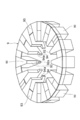
- FIG. 1 is a schematic perspective view of a combination weighing device according to an embodiment.
- Drawing 2 is a mimetic diagram for explaining the details of the guide ring in one embodiment.
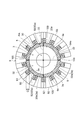
- FIG. 3 is a plan view of the combination weighing device shown in FIG. 1 as viewed from above in a substantially vertical direction.
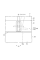
- FIG. 4 is a diagram illustrating a cross-sectional configuration of the dispersion table, the scraper, and the guide block.
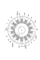
- FIG. 5 is a diagram for explaining a region through which the scraper passes.
- FIG. 6 is a plan view of the combination weighing device according to Modification 2 as viewed from above in the substantially vertical direction.
- FIG. 7 is a front view of the scraper of the combination weighing device according to Modification 3 as viewed from the front.
- FIG. 8 is a perspective view of the scraper of the combination weighing device in one of the modified examples 3 different from the scraper of FIG.
- FIG. 1 is a schematic perspective view of a combination weighing device 1 according to an embodiment.
- FIG. 2 is a schematic diagram for explaining the details of the guide ring 9 in one embodiment.
- FIG. 3 is a diagram of the combination weighing device 1 according to the embodiment as viewed from the upper side to the lower side in the substantially vertical direction.
- the configuration of the combination weighing device 1 will be described with reference to FIGS.
- the combination weighing device 1 is a device that measures articles (objects to be weighed) having variations in individual weights so as to have a total weight within an allowable range.
- the article include raw meats such as beef, pork and chicken.
- the combination weighing device 1 of the present embodiment can suitably weigh articles that are sticky and have two or more meat chunks connected by a streak and are not completely separated.
- the combination weighing device 1 includes a dispersion table (dispersion unit) 3, a plurality of transport units 5, a plurality of hoppers 7, and a guide ring 9.
- the dispersion table 3, the transport unit 5, the hopper 7 and the guide ring 9 are supported by the frame 10.
- the dispersion table 3 is a circular member in plan view.
- the distribution table 3 includes a first distribution unit 30 and a second distribution unit 32.
- the first dispersion portion 30 is a conical member centered on the central axis A.
- distribution part 30 has the conveyance surface 30a.
- the first dispersion unit 30 is connected to the second dispersion unit 32 at the bottom thereof.
- the second dispersion part 32 has a shape obtained by cutting away the apex from a conical shape having an apex angle larger than the apex angle of the first dispersion part 30.
- the second dispersion portion 32 is connected to the first dispersion portion 30 at a position corresponding to the excised top portion.
- the conveyance surface 32 a of the second dispersion unit 32 is different in inclination from the conveyance surface 30 a of the first dispersion unit 30. Thereby, the inclination of the transport surface 3a of the dispersion table 3 changes at the connection portion between the first dispersion unit 30 and the second dispersion unit 32.
- the dispersion table 3 is attached to a rotating shaft supported by a support portion 4 (see FIG. 4) disposed substantially below the dispersion table 3 in the vertical direction.
- the dispersion table 3 is detachable with respect to the rotating shaft.
- the rotating shaft is driven by a motor.
- the dispersion table 3 is rotated about the central axis A by a motor. At this time, the dispersion table 3 rotates while repeating clockwise rotation and counterclockwise rotation as viewed from above in a substantially vertical direction.
- the dispersion table 3 is rotated about the central axis A to convey (disperse) the articles supplied on the dispersion table 3 in a direction toward the outer edge 3e of the conveyance surface 3a of the dispersion table 3.
- the respective surfaces (conveying surface 30a and conveying surface 32a, that is, conveying surface 3a) of the first dispersing unit 30 and the second dispersing unit 32 in the dispersing table 3 are in a direction perpendicular to the surface. It has the protrusion part 33 which becomes convex. In short, the protrusion 33 has a convex shape upward with respect to the transport surface 3a.
- the protrusion 33 is formed from the central axis A of the dispersion table 3 to the outer edge 3 e of the dispersion table 3.
- the protrusion 33 in the present embodiment has an intersection at the rotation center of the dispersion table 3 and is arranged in a cross shape in plan view. In the above, the example in which the protrusions 33 are arranged in a cross shape has been described. However, any arrangement and any member may be used as long as the protrusion 33 has a convex shape with respect to the conveyance surface 3a. .
- the dispersion table 3 has a scraper (article removal unit) 100 in the vicinity of the outer edge 3e.
- the scraper 100 is disposed between the outer edge portion 3e and an end portion 92 of a guide block (partition portion) 90 described in detail later.
- the scraper 100 rotates in conjunction with the rotation operation of the dispersion table 3. That is, the scraper 100 rotates at the same rotational speed as the rotational speed per unit time in the dispersion table 3 and rotates in the same direction as the dispersion table 3.
- the rotating surface of the scraper 100 that rotates in accordance with the rotating operation of the dispersion table 3 is substantially horizontal.
- the scraper 100 rotates along a substantially horizontal plane in conjunction with the rotation operation of the dispersion table 3, so that articles staying between the outer edge portion 3 e and the end portion 92 are scraped out.
- the transport unit 5 includes a trough 52 and a screw 54 disposed on the trough 52.
- a plurality of troughs 52 are formed on the trough plate 50.
- the trough plate 50 has an annular shape in plan view.
- the inner diameter of the trough plate 50 is substantially the same as the outer diameter of the support portion 4 and is smaller than the outer diameter of the dispersion table 3. That is, the inner peripheral end of the trough plate 50 is located on the inner side of the outer edge portion 3 e of the dispersion table 3 when viewed from above along the central axis A.
- the trough 52 is a semi-cylindrical recess (concave groove).
- the troughs 52 are arranged radially from the center (central axis A) of the trough plate.
- the trough 52 extends from the center side (inner edge) to the outer edge of the trough plate.
- Screws 54 are disposed on each trough 52.
- the screw 54 is driven by a motor (not shown) disposed inside the support portion 4.
- the screw 54 rotates upon receiving the driving force of the motor.
- the conveyance unit 5 mainly composed of the trough 52 and the screw 54 is arranged radially along the outer edge 3e of the dispersion table 3.
- the conveyance unit 5 conveys the articles discharged from the dispersion table 3 along the troughs 52 with a rotating screw 54.
- An end of the transport unit 5 on the side of the dispersion table 3 serves as an article introduction unit 59.
- the hopper 7 is provided corresponding to each transport unit 5.
- the hopper 7 receives the article discharged from the transport unit 5. More specifically, the hopper 7 includes a pool hopper 70, a weighing hopper 72, and a booster hopper 74.
- the pool hopper 70, the weighing hopper 72, and the booster hopper 74 are arranged in this order from the top to the bottom.
- the pool hopper 70 temporarily holds the articles discharged from the transport unit 5.
- the weighing hopper 72 temporarily holds the articles discharged from the pool hopper 70.
- the weight of the article is measured by a weighing device (not shown).
- the booster hopper 74 temporarily holds the articles discharged from the weighing hopper 72.
- a set of the pool hopper 70, the weighing hopper 72, and the booster hopper 74 are provided corresponding to each of the transport units 5.
- the guide ring 9 has a plurality of guide blocks 90 arranged radially along the outer edge 3e of the dispersion table 3.
- the guide block 90 has a trapezoidal shape having an end 92 (top) on the outer edge 3e side of the dispersion table 3 in plan view.
- the guide blocks 90 adjacent to each other in the circumferential direction of the dispersion table 3 are connected by a connecting portion 93.
- An end surface (wall) 92a of the end portion 92 is a flat surface.
- a projecting portion 94 that projects from the end surface 92a toward the central axis
- a side (dispersion table 3 side) is provided below the end portion 92 of the guide block 90.
- the upper surface 94a of the protrusion 94 is a flat surface. In the case of this embodiment, a part of the articles supplied from the dispersion table 3 to the transport unit 5 temporarily stays on the upper surface 94a (until scraped out by the scraper 100).
- the protruding portion 94 is located on the inner side of the outer edge portion 3e of the dispersion table 3 in a plan view as viewed from above in a substantially vertical direction. As shown in FIG. 3, a gap G is formed between the end surface 92 a of the guide block 90 and the outer edge portion 3 e of the dispersion table 3.
- the article stays in the gap G.
- the scraper 100 rotates in conjunction with the rotation operation of the dispersion table 3. Therefore, the article is scraped from the gap G and supplied to one of the plurality of screws 54.
- FIG. 4 is a diagram showing a cross-sectional configuration of the dispersion table 3, the scraper 100, and the guide block 90.
- FIG. 5 is a view for explaining a passing area RA through which the scraper 100 passes.
- the dispersion table 3 has a first extending portion (extending portion) 42 extending downward from the conveying surface 30 a in a substantially vertical direction with the outer edge portion 3 e as a starting point. Furthermore, the distribution table 3 has a second extension portion 43 that extends in the inner direction of the distribution table 3 starting from the lower end of the first extension portion 42.
- the lower end of the first extending portion 42 may extend to such an extent that the second extending portion 43 and the upper surface 94a are in contact with each other.
- a spacer made of a resin or the like may be disposed between the second extending portion 43 and the upper surface 94a.
- the spacer attached to the second extending portion 43 rotates while sliding on the upper surface 94a.
- the spacer is resin and the upper surface 94a is a stainless steel member, the spacer rotates while changing its shape by sliding on the upper surface 94a.
- a scraper 100 is provided for the first extending portion 42.
- the scraper 100 may be welded to the first extending portion 42.
- it may be provided so as to be detachable from the first extending portion 42 by a bolt or the like.
- the scraper 100 may be configured to be detachably attached to the protrusion 33 with a bolt or the like.
- the scraper 100 is a member that scrapes out an article that stays on the upper surface 94 a in the gap G between the first extending portion 42 and the end surface 92 a of the guide block 90 and supplies it to one of the screws 54.
- the scraper 100 passes through a part of the passing area RA as shown in FIG. 5 as the dispersing table 3 rotates.
- the passing area RA is an annular area formed in a plan view formed when the distance from the outer edge 3e to the end surface 92a is rotated once around the rotation axis of the dispersion table 3.
- the passing area RA has the virtual circle in a plan view viewed from above in a substantially vertical direction when a circle centered on the central axis A and in contact with the end faces 92a of the plurality of guide blocks 90 is a virtual circle.
- the end surface 92a is an annular area formed in a plan view formed when the distance from the outer edge 3e to the end surface 92a is rotated once around the rotation axis of the dispersion table 3.
- the passing area RA has the virtual circle in a plan view viewed from above in a substantially vertical direction when a circle centered on the central axis A and in contact with the end faces 92a of the plurality of guide
- the scraper 100 may be attached so as to protrude in the same direction as the extending direction of the protrusion 33 attached to the surface of the dispersion table 3. Specifically, the scraper 100 may be attached in the vicinity of the end on the outer edge 3e side of the protrusion 33 so as to protrude in the same direction as the extending direction of the protrusion 33.
- the article falls into the gap G between the first extending portion 42 and the end surface 92 a, and at the same time, the article is scraped by the rotation of the scraper 100 and supplied to the screw 54. For this reason, in the present embodiment, it is possible to suppress the phenomenon that the article stays in the gap G between the first extending portion 42 and the end surface 92a while suppressing damage to the article when scraping the article.
- the scraper 100 has a first portion 101 and a second portion 102.
- the first portion 101 is a member attached to the first extending portion 42. Further, the first portion 101 extends toward the end surface 92a starting from the surface of the first extending portion 42 that faces the end surface 92a of the guide block 90.
- the first portion 101 is formed of a member that is less likely to change its shape by an external force as compared to the second portion 102.
- the first portion 101 is formed of a metal such as stainless steel, for example.
- the 1st part 101 may be welded to the 1st extension part 42, and may be provided with respect to the 1st extension part 42 so that attachment or detachment is possible. .
- the second part 102 is a member attached to the first part 101.
- the second portion 102 extends toward the end surface 92a from the outer end surface on the end surface 92a side of the first portion 101 as a starting point.
- the second portion 102 is formed of a member whose shape is easily changed by an external force as compared with the first portion 101.
- the second portion 102 is made of a material such as resin, for example.
- the second portion 102 may be provided to be detachable from the first portion 101.
- the scraper 100 When the dispersion table 3 rotates on the central axis A described above, the scraper 100 provided in the first extending portion 42 rotates along a substantially horizontal plane in conjunction with the rotation of the dispersion table 3.
- a part of the article slipped off from the outer edge 3e in the dispersion table 3 is directly supplied to the screw 54.
- Another part of the article is a gap G between the first extending portion 42 and the end surface 92a of the guide block 90, and is supplied onto the upper surface 94a.
- the article directly supplied to the screw 54 is conveyed as it is by the conveying force of the conveying unit 5.
- an article supplied to the upper surface 94a in the gap G between the first extending portion 42 and the end face 92a of the guide block 90 (hereinafter also simply referred to as “an article supplied to the gap G”). Since it does not receive the conveying force of the screw 54, it stays on the upper surface 94a of the guide block 90 as it is.
- the dispersion table 3 is continuously rotated, and the scraper 100 is also rotated in conjunction with the rotation. Therefore, even if the article supplied to the gap G stays on the upper surface 94 a, it is scraped from the upper surface 94 a by the scraper 100 and supplied to the screw 54. As a result, the article is conveyed by the conveying force of the screw 54.
- the scraper 100 when the scraper 100 is attached in the vicinity of the end portion on the outer edge 3e side of the protrusion 33, the article sliding along the protrusion 33 is positioned on the scraper 100 when falling on the upper surface 94a. In this state, when the scraper 100 rotates, the speed at which the article is scraped is slower than the speed for the article not located near the scraper 100. Therefore, damage at the time of scraping the article can be reduced.
- the second portion 102 and the end surface 92a are in contact with each other, the second portion 102 rotates while sliding on the end surface 92a. As a result, the article staying in the gap G between the second portion 102 and the end surface 92 a is reliably scraped out and supplied to the screw 54.
- the combination weighing device 1 is arranged along a dispersion table 3 that conveys an article supplied from the outside to the outside by rotation, and an outer edge portion 3e of the dispersion table 3, and the article to which the dispersion table 3 is conveyed.
- the scraper 100 is disposed in the gap G between the portion 92 and the outer edge portion 3e, and rotates about a central axis A of the dispersion table 3 along a substantially horizontal plane.
- the scraper 100 passes through a region where the distance from the outer edge portion 3e to the end portion 92 is rotated once around the central axis A in the dispersion table 3.
- the combination weighing device 1 rotates around the central axis A provided in a substantially vertical direction, thereby conveying the article supplied from above, and the outer edge of the dispersion table 3.
- a plurality of conveyance units 5 that are arranged radially along the part 3e and convey articles supplied from the dispersion table 3, a plurality of guide blocks 90 arranged between adjacent conveyance units 5, and a central axis A
- a scraper 100 that rotates along a substantially horizontal plane at the center.
- the scraper 100 When the circle centered on the central axis A and in contact with the end portions 92 on the outer edge 3e side of each of the plurality of guide blocks 90 is a virtual circle, the scraper 100 is a plan view viewed from above in a substantially vertical direction during rotation. , A part of the passing area RA between the virtual circle and the outer edge 3e is moved.
- the scraper 100 is disposed between the outer edge portion 3 e or the first extending portion 42 and the end portion 92 of the guide block 90.
- the scraper 100 passes through a passage area RA in which the distance from the outer edge 3e to the end 92 of the guide block 90 is rotated about the central axis A of the dispersion table 3.
- the scraper 100 moves in the passing area RA between the above-described virtual circle and the outer edge portion 3e in a plan view viewed from above in a substantially vertical direction. Therefore, even if the article stays in the gap G between the outer edge portion 3e or the first extending portion 42 and the end portion 92 of the guide block 90, the article is scraped out by the rotation of the scraper 100, and the article is transferred to the transport unit 5. Supplied.
- the article temporarily stays in the gap G between the outer edge portion 3e or the first extending portion 42 and the end 92 of the guide block 90, but is scraped by the rotation of the scraper 100. As a result, stagnation of articles can be suppressed.
- the scraper 100 may rotate in conjunction with the rotation of the dispersion table 3. In this configuration, it is not necessary to provide a separate mechanism for controlling the scraper 100, and the configuration can be simplified. Further, the scraper 100 may be rotated at the same rotational speed as the rotational speed per unit time in the dispersion table 3 and may be rotated in the same direction as the dispersion table 3.
- the end portion 92 of the guide block 90 has an end surface 92a extending in a substantially vertical direction, and the second portion 102 formed at the end portion on the guide block 90 side of the scraper 100 is in contact with the end surface 92a. It may be rotated. In this configuration, it is possible to scrape the article that has dropped onto the upper surface 94a more reliably.
- the dispersion table 3 may have a first extending portion 42 extending substantially downward in the vertical direction from the outer edge portion 3e of the dispersion table 3, and the scraper 100 may be provided in the first extending portion 42.
- the dispersion table 3 protrudes substantially vertically upward from the surface of the dispersion table 3 and has a convex protrusion on one formed from the rotation center of the dispersion table 3 to the outer edge 3e of the dispersion table 3. 33, and the scraper 100 may be provided in the first extending portion 42 in the vicinity of the protruding portion 33.
- the speed at which the scraper 100 contacts the article can be reduced. Thereby, the damage with respect to articles
- the first portion 101 located on the side of the dispersion table 3 in the scraper 100 is formed of a member that is less likely to change its shape due to external force as compared with the second portion 102 located on the guide block 90 side than the first portion 101. May be.
- some of the plurality of scrapers 100 rotate while sliding in contact with only the end surface 92a, and some of the other scrapers 100 slide while contacting only with the upper surface 94a. You may comprise so that it may rotate.
- the combination of the scraper that touches the end surface 92a and the scraper that touches the upper surface 94a can be freely designed.
- two scrapers 100 that touch the end surface 92a may be provided, and two scrapers 100 that may touch the upper surface 94a may be provided.
- the number of scrapers 100 can be freely designed (one or three or more), and the distribution of the number can be designed freely.
- end portion on the end surface 92a side of the second portion 102 may be configured in a comb shape. In short, any shape may be used as long as it can scrape out the staying article.
- the article removal unit may be configured as a protruding member 200 that protrudes from the first extending portion 42 (see FIG. 4) toward the end 92 of the guide block 90.
- the protruding member 200 is formed in a triangular shape such that one apex faces the end portion 92 in a plan view as viewed from above in a substantially vertical direction.
- four protrusion members 200 may be arrange
- the protruding member 200 is formed of a metal member such as stainless steel, for example.
- the protruding member 200 is fixed to the first extending portion 42 with a bolt or the like.
- the article is not pushed out in the tangential direction of the circle as in the scraper 100 of the above embodiment, but is moved outward regardless of the rotation direction (forward rotation or reverse rotation). Power is generated. For this reason, even if the gap G between the first extending portion 42 and the end surface 92a is substantially horizontal, the article can be moved in the direction in which it is desired to move. Furthermore, if the position of the dispersion table 3 during rotation is controlled, it is possible to prevent the article from entering the gap G when the article is inserted.
- the scraper 100 or the protruding member 200 may be provided so as to be movable along the outer edge portion 3e (circumferential direction of the dispersion table 3) with respect to the protruding portion 33.
- the scraper 100 is provided so as to be movable along the outer edge 3e with respect to the protrusion 33.
- the scraper 100 is fixed to the first extending portion 42 of the dispersion table 3 with bolts 213. More specifically, the first extending portion 42 is formed with an insertion hole 214 extending in the circumferential direction D1 along the outer edge portion 3e, and the scraper 100 has a bolt 213 inserted into the insertion hole 214. Fixed by. Since the insertion hole 214 is long in the circumferential direction D1 along the outer edge portion 3e, the position where the bolt 213 is inserted can be moved along the circumferential direction D1. Therefore, the position where the scraper 100 is fixed to the first extending portion 42 can also be changed along the circumferential direction D1.
- the scraper 100 is slidable along the circumferential direction D1 with respect to the projecting protrusion 33 attached on the dispersion table 3. That is, the user can adjust the attachment position of the scraper 100 with respect to the convex-shaped protrusion 33.
- the scraper 100 or the protruding member 200 spreads radially from the rotation center of the dispersion table 3 in a direction where the outer edge 3e of the dispersion table 3 is present with respect to the protrusion 33 as viewed from the rotation center of the dispersion table 3. It may be provided so as to be movable in the direction, in other words, in the radial direction of the dispersion table 3 (hereinafter, this direction is referred to as “radial direction D2”).
- the protruding portion 33 extends in the radial direction of the dispersion table 3, it can be said that the scraper 100 is provided to be movable in the extending direction of the protruding portion 33 with respect to the protruding portion 33.
- FIG. 1 an example of a configuration in which the scraper 100 is provided so as to be movable in the radial direction D2 with respect to the protrusion 33 will be described with reference to FIG.
- two long holes 33 ⁇ / b> A and 33 ⁇ / b> A extending along the radial direction of the dispersion table 3 are formed in the protrusion 33.
- the scraper 100 is fixed to the protrusion 33 via the adjustment plate 320.
- the adjustment plate 320 is fixed to the protrusion 33 by a bolt 311 and a nut 313. Specifically, a bolt 311 inserted through a hole (not shown) formed in the adjustment plate 320 from the adjustment plate 320 side and the elongated hole 33A of the protrusion 33 is fixed by a nut 313 from the protrusion 33 side.
- the bolt 311 can move in the radial direction D2 within the range of the length of the long hole 33A in the radial direction D2. That is, the adjustment plate 320 can move in the radial direction D2 with respect to the protrusion 33 within the range of the length of the long hole 33A in the radial direction D2.
- the scraper 100 fixed to the adjustment plate 320 can also adjust the position in the radial direction D2 with respect to the protrusion 33. By setting it as the said structure, the scraper 100 becomes slidable along radial direction D2 with respect to the convex-shaped projection part 33 attached on the dispersion
- One embodiment of the present disclosure is applicable to a combination weighing device in which an article stays between a dispersion unit and a partition unit.
- an embodiment of the present disclosure can be applied to an apparatus for weighing an article having adhesiveness such as a raw lever and containing a lot of moisture.
Landscapes
- Physics & Mathematics (AREA)
- General Physics & Mathematics (AREA)
- Feeding Of Articles To Conveyors (AREA)
- Branching, Merging, And Special Transfer Between Conveyors (AREA)
Abstract
組合せ計量装置(1)は、略鉛直方向に設けられた回転軸(A)を中心に回転することにより、上方から供給される物品を搬送する分散テーブル(3)と、分散部の外縁部(3e)に沿って放射状に配置され、分散テーブルから供給される物品を搬送する複数の搬送部(5)と、隣接する搬送部の間に配置される複数のガイドブロック90と、回転軸を中心に略水平面に沿って回転するスクレーパー100と、を備え、複数のガイドブロックにおけるそれぞれの外縁部側の端部に接する、回転軸を中心とする円を仮想円としたとき、スクレーパー100は、平面視において仮想円と外縁部との間の領域のうち少なくとも一部の領域を回転時に移動する。
Description
本発明は、組合せ計量装置に関する。
特許文献1は、分散テーブルの側面および放射トラフにかけて、分散テーブルの滑落面に商品が付着しないように強制的に物品を滑落させるスクレーパー等が設けられる組合せ計量装置を開示する。スクレーパー等の物品除去部は、分散テーブルのコーンの周面を周回して滑落面に付着した商品を剥離して、下方のガイドポケット方向に払い落とす。
また、特許文献2は、分散テーブルを取り囲む環状のガイドリングを有する組合せ計量装置を開示する。ガイドリングは、中心軸を中心とする周方向に一定の間隔をあけて形成された、トラフの数に対応した複数の数のガイドブロック(案内部)を有する。このガイドブロックに形成されたコーナー部は、滑らかな円筒面を有する。その作用により、物品(被計量物)は、そのコーナー部に引っかかって滞留することなく、左右に振分けられる。
上記のように、ガイドブロックにコーナー部を形成する場合であっても、例えば2つの肉塊が筋繊維等の筋で繋がれている場合、そのコーナー部に当該筋が引っかかる。そのように肉塊がコーナー部に引っかかった場合、分散テーブル又はコイルユニットをいくら回転させたとしても、引っかかった肉塊を取り除くのが困難となる。
上記のような肉塊の引っ掛かりを除去するため、特許文献1に開示されるように分散テーブルの周面を周回するスクレーパー等の分散装置を取り付けることが考えられる。
しかしながら、一般的に、物品が挟み込まれるのを低減させるため、特許文献2における図1に示すように、分散テーブルとガイドリングにおけるコーナー部との間はできるだけ狭くなるように設計される。このような場合、特許文献1に記載されるような分散テーブルの周面を周回するスクレーパー等の物品除去部をそのままでは取り付けることができない。
本発明の一側面は、仕切部を設けた従来の組合せ計量装置と比較して、肉塊が仕切部に引っかかる状態を抑止することができる組合せ計量装置を提供することを目的とする。
本発明の一側面に係る組合せ計量装置は、鉛直方向に設けられた回転軸を中心に回転することにより、上方から供給される物品を搬送する分散部と、分散部の外縁部に沿って放射状に配置され、分散部から供給される物品を搬送する複数の搬送部と、隣接する搬送部の間に配置される複数の仕切部と、回転軸を中心に水平面に沿って回転する物品除去部と、を備え、複数の仕切部におけるそれぞれの外縁部側の端部に接する、回転軸を中心とする円を仮想円としたとき、物品除去部は、回転時に、鉛直方向上方から見た平面視において、仮想円と外縁部との間の領域のうち少なくとも一部の領域を移動する。
本発明の一側面に係る組合せ計量装置は、鉛直方向に設けられた回転軸を中心に回転することにより、外部から供給される物品を外側に搬送する分散部と、分散部の外縁部に沿って配置され、分散部が搬送される物品を受け取りさらに搬送する複数の搬送部と、搬送部の間に配置される仕切部と、仕切部の外縁部側の端部と、外縁部との間に配置され、回転軸を中心に水平面上を回転するスクレーパーと、を備え、スクレーパーは、外縁部から仕切部の外縁部側の端部までの距離を、回転軸を中心に一回転させた領域を通過する。
なお、ここでいう水平には略水平が含まれ、鉛直には略鉛直が含まれる。
本発明の一側面によれば、仕切部を設けた従来の組合せ計量装置と比較して、肉塊が仕切部に引っかかる状態を抑止することができる。
以下、適宜図面を参照しながら、実施形態の例を詳細に説明する。但し、必要以上に詳細な説明は省略する場合がある。例えば、既によく知られた事項の詳細説明や実質的に同一の構成に対する重複説明を省略する場合がある。これは、以下の説明が不必要に冗長になるのを避け、当業者の理解を容易にするためである。
なお、発明者は、当業者が実施形態を十分に理解するために添付図面および以下の説明を提供するのであって、これらによって特許請求の範囲に記載の主題を限定することを意図するものではない。
図1は、一実施形態に係る組合せ計量装置1の模式的な斜視図である。図2は、一実施形態におけるガイドリング9の詳細を説明するための模式図である。図3は、一実施形態における組合せ計量装置1を略鉛直方向上方から下方に向けて見た図である。
図1~図5を用いて、一実施形態に係る組合せ計量装置1における構成を説明する。組合せ計量装置1は、個々の重量にばらつきがある物品(被計量物)を許容範囲内の合計重量となるように計り分ける装置である。物品としては、牛肉、豚肉および鶏肉等の生肉類等が挙げられる。本実施形態の組合せ計量装置1は、特に、粘着性を有し、2以上の肉塊が筋により繋がれており完全には切り離されていない物品を好適に計量できる。
図1に示されるように、組合せ計量装置1は、分散テーブル(分散部)3と、複数の搬送部5と、複数のホッパ7と、ガイドリング9と、を備える。分散テーブル3、搬送部5、ホッパ7およびガイドリング9は、フレーム10によって支持される。
分散テーブル3は、平面視において円形状の部材である。分散テーブル3は、第1分散部30と、第2分散部32と、を有する。第1分散部30は、中心軸Aを中心とする円錐形状の部材である。第1分散部30は、搬送面30aを有している。第1分散部30は、その底部において第2分散部32に接続される。
第2分散部32は、第1分散部30の頂角よりも大きな頂角を有する円錐形状から、その頂部を切除した形状を呈する。第2分散部32は、その切除された頂部に対応する位置において第1分散部30に接続される。第2分散部32の搬送面32aは、第1分散部30の搬送面30aと傾きが異なる。これにより、分散テーブル3の搬送面3aは、第1分散部30と第2分散部32との接続部分において、傾きが変化する。
分散テーブル3は、分散テーブル3の略鉛直方向下方に配置される支持部4(図4参照)に支持された回転軸に取り付けられる。分散テーブル3は、回転軸に対して着脱自在である。回転軸は、モータによって駆動される。分散テーブル3は、モータによって中心軸Aを中心として回転する。このとき、分散テーブル3は、略鉛直方向上方から見て時計回りの回転と、反時計周りの回転とを交互に繰り返しながら回転する。
分散テーブル3は、中心軸Aを中心として回転することにより、分散テーブル3上に供給された物品を、分散テーブル3の搬送面3aの外縁部3eに向かう方向に搬送(分散)させる。
図3に示されるように、分散テーブル3における第1分散部30および第2分散部32のそれぞれの表面(搬送面30a及び搬送面32a、すなわち搬送面3a)は、当該表面と直交する方向に凸となる突起部33を有する。要するに、突起部33は、搬送面3aに対して上方に凸型形状となる。突起部33は、分散テーブル3の中心軸Aから分散テーブル3における外縁部3eにかけて形成される。本実施形態における突起部33は、分散テーブル3の回転中心に交点を有し、平面視において十字形状に配置される。上記において突起部33は十字形状に配置される例を説明したが、搬送面3aに対して上方に凸型形状となる構成であればどのような配置、どのような部材を利用してもよい。
分散テーブル3は、外縁部3e近傍に、スクレーパー(物品除去部)100を有する。スクレーパー100は、外縁部3eと後段にて詳述するガイドブロック(仕切部)90の端部92との間に配置される。スクレーパー100は、分散テーブル3の回転動作と連動して回転する。すなわち、スクレーパー100は、分散テーブル3における単位時間あたりの回転数と同じ回転数で回転すると共に、分散テーブル3と同方向に回転する。分散テーブル3の回転動作に伴って回転するスクレーパー100の回転面は、略水平となる。スクレーパー100が分散テーブル3の回転動作と連動して略水平面に沿って回転することにより、外縁部3eと端部92との間に滞留する物品が掻き出される。
図3及び図4に示されるように、搬送部5は、トラフ52と、トラフ52に配置されたスクリュー54を有する。トラフ52は、トラフプレート50に複数形成される。トラフプレート50は、平面視において円環状を呈する。トラフプレート50の内径は、支持部4の外径と略同等であり、分散テーブル3の外径よりも小さい。すなわち、トラフプレート50の内周端は、中心軸Aに沿って上方から見たとき、分散テーブル3の外縁部3eよりも内側に位置する。
トラフ52は、半円柱状の凹部(凹状溝)である。トラフ52は、トラフプレートの中心(中心軸A)から放射状に配置される。トラフ52は、トラフプレートの中心側(内縁)から外縁にわたって延在する。
スクリュー54は、トラフ52のそれぞれに配置される。スクリュー54は、支持部4の内側に配置されたモータ(図示しない)によって駆動される。スクリュー54は、モータの駆動力を受けて回転する。主にトラフ52とスクリュー54とによって構成される搬送部5は、分散テーブル3の外縁部3eに沿って放射状に配置される。搬送部5は、分散テーブル3から排出される物品を、回転するスクリュー54によってトラフ52に沿って搬送する。搬送部5の分散テーブル3側の端部は、物品の導入部59となる。
図1に示されるように、ホッパ7は、搬送部5ごとに対応して設けられる。そして、ホッパ7は、搬送部5から排出された物品を受ける。より具体的にホッパ7は、プールホッパ70と、計量ホッパ72と、ブースターホッパ74と、を有する。プールホッパ70、計量ホッパ72およびブースターホッパ74は、上方から下方に向かってこの順に並んで配列される。
プールホッパ70は、搬送部5から排出された物品を一時的に保持する。計量ホッパ72は、プールホッパ70から排出された物品を一時的に保持する。計量ホッパ72では、図示しない計量装置によって、物品の重量が計測される。ブースターホッパ74は、計量ホッパ72から排出された物品を一時的に保持する。本実施形態では、これらの1組のプールホッパ70、計量ホッパ72、およびブースターホッパ74が、搬送部5のそれぞれに対応して設けられる。
図2及び図3に示されるように、ガイドリング9は、分散テーブル3の外縁部3eに沿って放射状に配列された複数のガイドブロック90を有する。ガイドブロック90は、平面視において、分散テーブル3の外縁部3e側に端部92(頂部)を有する台形形状を有する。分散テーブル3の周方向に隣り合うガイドブロック90同士は、連結部93によって連結される。端部92の端面(壁)92aは、平坦面である。ガイドブロック90の端部92の下部には、端面92aから中心軸A側(分散テーブル3側)に突出する突出部94が設けられる。突出部94の上面94aは、平坦面である。本実施形態の場合、分散テーブル3から搬送部5に供給される物品の一部は、この上面94aに(スクレーパー100によって掻き出されるまで)一時的に滞留する。
分散テーブル3およびガイドリング9が取り付けられた状態において、突出部94は、略鉛直方向上方から見た平面視において、分散テーブル3の外縁部3eよりも内側に位置する。図3に示されるように、ガイドブロック90の端面92aと分散テーブル3の外縁部3eとの間には、隙間Gが形成されている。
隙間Gには、物品が滞留する。本実施形態では、分散テーブル3の回転動作と連動してスクレーパー100が回転する。そのため、物品はこの隙間Gから掻き出され、複数のスクリュー54のいずれかに供給される。
以下、分散テーブル3、スクレーパー100およびガイドブロック90の関係について図面を参照しながら詳細に説明する。
図4は、分散テーブル3、スクレーパー100およびガイドブロック90の断面構成を示す図である。図5は、スクレーパー100が通過する通過領域RAを説明するための図である。
図4に示されるように、分散テーブル3は、外縁部3eを起点として搬送面30aから略鉛直方向下方に延在する第1延在部(延設部)42を有する。さらに、分散テーブル3は、第1延在部42の下端を起点して分散テーブル3の内部方向に延在する第2延在部43を有する。
ここで、第1延在部42の下端は、第2延在部43と上面94aとが接する程度に延在してもよい。また、樹脂等で構成されるスペーサーが、第2延在部43と上面94aとの間に配置されてもよい。この場合、分散テーブル3が回転すると、例えば、第2延在部43に取り付けられたスペーサーが上面94aを摺動しながら回転する。例えば、スペーサーが樹脂であり、上面94aがステンレス製の部材である場合、スペーサーは、上面94aを摺動することにより、その形状を変化させながら回転する。
また、第1延在部42に対してスクレーパー100が設けられる。この場合、スクレーパー100は、第1延在部42に溶接されてもよい。また、ボルト等により第1延在部42に対して着脱可能に設けられてもよい。さらに、スクレーパー100は、突起部33に対してボルト等により着脱可能に取り付けられる構成でも構わない。
スクレーパー100は、第1延在部42とガイドブロック90の端面92aとの隙間Gであって上面94a上に滞留する物品を掻き出して、いずれかのスクリュー54に供給する部材である。
さらに、スクレーパー100は、分散テーブル3の回転に伴って、図5に示されるような通過領域RAのうち一部の領域を通過する。ここで、通過領域RAは、外縁部3eから端面92aまでの距離を、分散テーブル3における回転軸を中心に一回転させたときに形成される、平面視において円環状の領域である。言い換えれば、通過領域RAは、複数のガイドブロック90におけるそれぞれの端面92aに接する、中心軸Aを中心とする円を仮想円としたとき、略鉛直方向上方から見た平面視において、上記仮想円と端面92aとの間の領域である。
スクレーパー100は、分散テーブル3の表面に取り付けられる突起部33の延在方向と同じ方向に突出するように取り付けてもよい。具体的には、スクレーパー100は、突起部33のうち外縁部3e側における端部近傍に、突起部33の延在方向と同じ方向に突出するように取り付けてもよい。このように取り付ける構成にすることで、突起部33に沿って分散テーブル3の搬送面3aを滑り落ちた物品は、そのままスクレーパー100と接触する位置に落下する。これにより、物品は、第1延在部42と端面92aとの隙間Gに落下すると同時に、スクレーパー100の回転により掻き出され、スクリュー54に供給される。このため、本実施形態では、物品に対する掻き出し時の物品に対するダメージを抑制しながら、第1延在部42と端面92aとの隙間Gに物品が滞留する現象を抑制できる。
スクレーパー100は、第1部分101と第2部分102とを有する。第1部分101は、第1延在部42に対して取り付けられる部材である。さらに、第1部分101は、第1延在部42のうちガイドブロック90の端面92aと対向する面を起点として、端面92a側に向かって延在する。第1部分101は、第2部分102と比較して、外力によって形状変化しにくい部材で形成される。第1部分101は、例えばステンレススチール等の金属で形成される。第1部分101が金属部材で形成される場合、第1部分101は、第1延在部42に溶接されてもよいし、第1延在部42に対して着脱可能に設けられてもよい。
第2部分102は、第1部分101に対して取り付けられる部材である。第2部分102は、第1部分101のうち端面92a側の外端面を起点として、端面92a側に向かって延在する。第2部分102は、第1部分101と比較して、外力によって形状変化しやすい部材で形成される。第2部分102は、例えば樹脂等の素材で形成される。第2部分102は、第1部分101に対して着脱可能に設けられてもよい。
ここで、スクレーパー100の作用について説明する。分散テーブル3が上記で説明した中心軸Aで回転する場合、第1延在部42に設けられるスクレーパー100は、分散テーブル3の回転と連動して略水平面に沿って回転する。
分散テーブル3が回転動作することにより、外部から分散テーブル3に供給された物品は、当該回転動作に起因する遠心力により、分散テーブル3の搬送面3a上を滑り落ちる。このとき、分散テーブル3の表面(搬送面3a)に設けられた突起部33の作用により、一部の物品は、突起部33に沿って外縁部3eに向かって滑り落ちる。
分散テーブル3における外縁部3eから滑り落ちた物品の一部は、スクリュー54に直接供給される。また、上記物品の他の一部は、第1延在部42とガイドブロック90の端面92aとの間の隙間Gであって上面94a上に供給される。スクリュー54に直接供給された物品は、そのまま搬送部5の搬送力により搬送される。一方、第1延在部42とガイドブロック90の端面92aとの間の隙間Gであって上面94a上に供給された物品(以下、単に「隙間Gに供給された物品」とも称する。)は、スクリュー54の搬送力を受けないため、そのままガイドブロック90の上面94aで滞留する。
ここで、分散テーブル3は連続して回転しており、その回転と連動してスクレーパー100も回転する。そのため、隙間Gに供給された物品が上面94a上に滞留しても、スクレーパー100によって上面94a上から掻き出され、スクリュー54に供給される。その結果、物品は、スクリュー54の搬送力によって搬送される。
また、突起部33のうち外縁部3e側における端部近傍にスクレーパー100が取付けられる場合、突起部33に沿って滑落する物品は、上面94aに落下した場合、スクレーパー100に位置することとなる。この状態において、スクレーパー100が回転する場合、物品を掻き出す速度は、スクレーパー100付近に位置しない物品に対する速度と比較して遅くなる。そのため、物品に対する掻き出し時のダメージが低減できる。
さらに、第2部分102と端面92aとが接触する場合には、第2部分102は、端面92aを摺動しながら回転する。これにより、第2部分102と端面92aとの間の隙間Gに滞留する物品は確実に掻き出され、スクリュー54に供給される。
本実施形態における組合せ計量装置1の作用効果について説明する。本実施形態における組合せ計量装置1は、外部から供給される物品を、回転によって外側に搬送する分散テーブル3と、分散テーブル3の外縁部3eに沿って配置され、分散テーブル3が搬送される物品を受け取りさらに搬送する複数の搬送部5と、搬送部5の間に配置されるガイドブロック90と、ガイドブロック90の外縁部3e側の端部92と、ガイドブロック90の外縁部3e側の端部92と、外縁部3eとの間の隙間Gに配置され、分散テーブル3の中心軸Aを中心に略水平面に沿って回転するスクレーパー100と、を備える。そして、スクレーパー100は、外縁部3eから端部92までの距離を、分散テーブル3における中心軸Aを中心に一回転させた領域を通過する。
言い換えれば、本実施形態における組合せ計量装置1は、略鉛直方向に設けられた中心軸Aを中心に回転することにより、上方から供給される物品を搬送する分散テーブル3と、分散テーブル3の外縁部3eに沿って放射状に配置され、分散テーブル3から供給される物品を搬送する複数の搬送部5と、隣接する搬送部5の間に配置される複数のガイドブロック90と、中心軸Aを中心に略水平面に沿って回転するスクレーパー100と、を備える。複数のガイドブロック90におけるそれぞれの外縁部3e側の端部92に接する、中心軸Aを中心とする円を仮想円としたとき、スクレーパー100は、回転時に、略鉛直方向上方から見た平面視において、仮想円と外縁部3eとの間の通過領域RAの一部を移動する。
分散テーブル3が回転することにより、物品は、分散テーブル3の表面を滑り落ちる。分散テーブル3の表面を滑り落ちた物品は、外縁部3eまたは第1延在部42と、端部92との間であって上面94a上に滞留する。本実施形態では、外縁部3eまたは第1延在部42と、ガイドブロック90における端部92との間に、スクレーパー100が配置される。スクレーパー100は、外縁部3eからガイドブロック90における端部92までの距離を、分散テーブル3における中心軸Aを中心に一回転させた通過領域RAを通過する。すなわち、スクレーパー100は、略鉛直方向上方から見た平面視において、上述した仮想円と外縁部3eとの間の通過領域RAを移動する。よって、外縁部3eまたは第1延在部42と、ガイドブロック90における端部92との間の隙間Gに物品が滞留したとしても、スクレーパー100の回転により掻き出され、搬送部5に物品が供給される。
すなわち、外縁部3eまたは第1延在部42と、ガイドブロック90における端部92との間の隙間Gには、一時的に物品が滞留するが、スクレーパー100の回転により掻き出されるので、結果として物品の滞留を抑制できる。
スクレーパー100は、分散テーブル3の回転と連動して回転してもよい。この構成では、別途スクレーパー100を制御する機構を設ける必要がなく構成を簡便化できる。また、スクレーパー100は、分散テーブル3における単位時間あたりの回転数と同じ回転数で回転、かつ分散テーブル3と同方向に回転させてもよい。
また、ガイドブロック90の端部92は、略鉛直方向に延びる端面92aを有しており、スクレーパー100のガイドブロック90側の端部に形成される第2部分102は、端面92aに接触しながら回転させてもよい。この構成では、より確実に上面94aに落下した物品を掻き出せる。
また、分散テーブル3は、分散テーブル3における外縁部3eから略鉛直方向下向きに延びる第1延在部42を有しており、スクレーパー100は、第1延在部42に設けてもよい。
また、分散テーブル3は、分散テーブル3における表面から略鉛直方向上方に突出すると共に、分散テーブル3における回転中心から分散テーブル3における外縁部3eにわたって形成される一つの上に凸型形状の突起部33を有し、スクレーパー100は、第1延在部42において突起部33の近傍に設けてもよい。この構成では、突起部33に沿って分散テーブル3を滑落する物品のうち一部の物品は、スクレーパー100近傍に落下する。そのため、スクレーパー100が物品に接触する速度を小さくできる。これにより、物品に対するダメージを小さくできる。
また、スクレーパー100において分散テーブル3側に位置する第1部分101は、第1部分101よりもガイドブロック90側に位置する第2部分102と比較して、外力によって形状変化しにくい部材で形成されてもよい。
以上のように、本発明における技術の例示として、一実施形態を説明した。そのために、添付図面および詳細な説明を提供した。本発明は、上記実施形態に限られず、発明の趣旨を逸脱しない範囲で種々の変更が可能である。
(変形例1)
上記実施形態においては、スクレーパー100が端面92aに接触しながら回転する動作を説明した。しかしながら、この構成に限定されず、スクレーパー100は、端面92aおよび上面94aのいずれの面に対しても触れながら摺動し、回転するように構成してもよい。この場合、スクレーパー100における第2部分102が上面94aに触れる構成としてもよい。第1部分101は、第2部分102よりも硬質な素材で構成されてもよい。そのため、第1部分101が上面94aに摺動しながら回転すると、上面94aを傷つけてしまうおそれがある。
上記実施形態においては、スクレーパー100が端面92aに接触しながら回転する動作を説明した。しかしながら、この構成に限定されず、スクレーパー100は、端面92aおよび上面94aのいずれの面に対しても触れながら摺動し、回転するように構成してもよい。この場合、スクレーパー100における第2部分102が上面94aに触れる構成としてもよい。第1部分101は、第2部分102よりも硬質な素材で構成されてもよい。そのため、第1部分101が上面94aに摺動しながら回転すると、上面94aを傷つけてしまうおそれがある。
また、複数存在するスクレーパー100のうち一部は、端面92aのみと接触した状態で摺動しながら回転し、他のスクレーパー100のうち一部は、上面94aとのみ接触した状態で摺動しながら回転するように構成してもよい。
要するに、複数のスクレーパー100が存在する場合、端面92aに触れるスクレーパーと上面94aに触れるスクレーパーの組合せは自由に設計することができる。例えば、端面92aに触れるスクレーパー100を2枚有し、上面94aに触れるスクレーパー100を2枚有する構成としてもよい。さらに、端面92aに触れるスクレーパー100を2枚有し、上面94aに触れるスクレーパー100を4枚有する構成としてもよい。要するに、スクレーパー100の数は自由に設計でき(1枚であってもよいし、3枚以上であってもよい)、その数の配分も自由に設計できる。
また、第2部分102における端面92a側の端部は、櫛形状である構成にしてもよい。要するに、滞留する物品を掻き出すことができる構成であればどのような形状であってもよい。
(変形例2)
上記実施形態又は上記変形例では、物品除去部の例として、第1部分101と第2部分102とからなるスクレーパー100を例に挙げて説明したが、本発明はこれに限定されない。例えば、物品除去部は、図6に示されるように、第1延在部42(図4参照)からガイドブロック90における端部92に向かって突出する突出部材200として構成されてもよい。突出部材200は、略鉛直方向上方から見た平面視において、一の頂点が端部92に対向するような三角形状に形成される。また、突出部材200は、図6に示されるように4つ配置されてもよいし、4つ以外の数が配置されてもよい。突出部材200は、例えば、ステンレススチール等の金属製の部材から形成される。突出部材200は、第1延在部42に対し、ボルト等により固定される。
上記実施形態又は上記変形例では、物品除去部の例として、第1部分101と第2部分102とからなるスクレーパー100を例に挙げて説明したが、本発明はこれに限定されない。例えば、物品除去部は、図6に示されるように、第1延在部42(図4参照)からガイドブロック90における端部92に向かって突出する突出部材200として構成されてもよい。突出部材200は、略鉛直方向上方から見た平面視において、一の頂点が端部92に対向するような三角形状に形成される。また、突出部材200は、図6に示されるように4つ配置されてもよいし、4つ以外の数が配置されてもよい。突出部材200は、例えば、ステンレススチール等の金属製の部材から形成される。突出部材200は、第1延在部42に対し、ボルト等により固定される。
このような突出部材200によれば、上記実施形態のスクレーパー100のように、物品を円の接線方向に押し出すのではなく、回転方向(正回転又は逆回転)にかかわらず、外側方向へ移動させる力が生じる。このため、第1延在部42と端面92aとの隙間Gを略水平面にしても、物品を移動させたい方向へ移動させることができる。さらに、分散テーブル3の回転時における位置を制御すれば、物品投入時には上記隙間Gに物品が入らないようにすることも可能となる。
(変形例3)
上記実施形態又は上記変形例の構成に加えて、スクレーパー100又は突出部材200は、突起部33に対し、外縁部3eに沿って(分散テーブル3の円周方向)移動可能に設けられてもよい。ここでは、図7を用いて、スクレーパー100が、突起部33に対し、外縁部3eに沿って移動可能に設けられている構成の一例を説明する。
上記実施形態又は上記変形例の構成に加えて、スクレーパー100又は突出部材200は、突起部33に対し、外縁部3eに沿って(分散テーブル3の円周方向)移動可能に設けられてもよい。ここでは、図7を用いて、スクレーパー100が、突起部33に対し、外縁部3eに沿って移動可能に設けられている構成の一例を説明する。
スクレーパー100は、分散テーブル3における第1延在部42に対し、ボルト213により固定される。より具体的には、第1延在部42には、外縁部3eに沿う周方向D1に延在する挿通孔214が形成されており、スクレーパー100は、当該挿通孔214に挿通されたボルト213によって固定される。挿通孔214は、外縁部3eに沿う周方向D1に長いので、ボルト213を挿通させる位置は、上記周方向D1に沿って移動が可能である。したがって、第1延在部42に対してスクレーパー100を固定する位置も、周方向D1に沿って変更が可能である。
上記のような変形例3の構成とすることにより、スクレーパー100は、分散テーブル3上に取り付けられた凸型形状の突起部33に対して周方向D1に沿ってスライド自在となる。すなわち、使用者は、凸型形状の突起部33に対するスクレーパー100の取付位置を調整できる。
また、スクレーパー100又は突出部材200は、突起部33に対し、分散テーブル3における回転中心から見て分散テーブル3における外縁部3eがある方向に、言い換えれば、分散テーブル3における回転中心から放射状に広がる方向に、さらに言い換えれば、分散テーブル3の径方向に、移動可能に設けられてもよい(以後、この方向を「径方向D2」と称する。)。また、突起部33は分散テーブル3の径方向に延在するので、スクレーパー100は、突起部33に対し、突起部33の延在方向に移動可能に設けられるとも言える。ここでは、図8を用いて、スクレーパー100が、突起部33に対し、径方向D2に移動可能に設けられる構成の一例を説明する。
図8に示されるように、突起部33には、分散テーブル3の径方向に沿って延在する長孔33A,33Aが二つ形成される。スクレーパー100は、調整プレート320を介して突起部33に固定される。調整プレート320は、ボルト311とナット313とによって突起部33に固定される。具体的には、調整プレート320側から調整プレート320に形成された孔(図示せず)と突起部33の長孔33Aとに挿通されたボルト311を突起部33側からナット313によって固定する。
ボルト311は、径方向D2における長孔33Aの長さの範囲で径方向D2への移動が可能となる。すなわち、調整プレート320は、径方向D2における長孔33Aの長さの範囲で突起部33に対し径方向D2への移動が可能になる。上記調整プレート320に固定されたスクレーパー100もまた、突起部33に対し、径方向D2への位置調整が可能になる。上記構成とすることにより、スクレーパー100は、分散テーブル3上に取り付けられた凸型形状の突起部33に対して径方向D2に沿ってスライド自在となる。すなわち、使用者は、凸型形状の突起部33に対するスクレーパー100の取付位置を調整できる。
添付図面および詳細な説明に記載された構成要素の中には、課題解決のために必須な構成要素だけでなく、上記技術を例示するために、課題解決のためには必須でない構成要素も含まれ得る。そのため、それらの必須ではない構成要素が添付図面や詳細な説明に記載されていることをもって、直ちに、それらの必須ではない構成要素が必須であるとの認定をするべきではない。
また、上述の一実施形態は、本開示における技術を例示するためのものであるから、特許請求の範囲またはその均等の範囲において種々の変更、置き換え、付加、省略などを行うことができる。
本開示の一実施形態は、物品が分散部と仕切部との間に滞留する組合せ計量装置に適用可能である。具体的には、生レバー等の粘着性を有し水分を多く含む物品を計量する装置などに、本開示の一実施形態は適用可能である。
1…組合せ計量装置、3…分散テーブル、3a…搬送面、3e…外縁部、4…支持部、5…搬送部、7…ホッパ、9…ガイドリング、10…フレーム、30…第1分散部、32…第2分散部、33…突起部、42…第1延在部(延設部)、43…第2延在部、50…トラフプレート、52…トラフ、54…スクリュー、59…導入部、70…プールホッパ、72…計量ホッパ、74…ブースターホッパ、90…ガイドブロック(仕切部)、92…端部、92a…端面(壁)、94…突出部、94a…突出部の上面、100…スクレーパー(物品除去部)、101…第1部分、102…第2部分、200…突出部材(物品除去部)、320…調整プレート、A…中心軸、G…隙間、RA…通過領域。
Claims (10)
- 鉛直方向に設けられた回転軸を中心に回転することにより、上方から供給される物品を搬送する分散部と、
前記分散部の外縁部に沿って放射状に配置され、前記分散部から供給される物品を搬送する複数の搬送部と、
隣接する前記搬送部の間に配置される複数の仕切部と、
前記回転軸を中心に水平面に沿って回転する物品除去部と、を備え、
前記複数の仕切部におけるそれぞれの前記外縁部側の端部に接する、前記回転軸を中心とする円を仮想円としたとき、
前記物品除去部は、回転時に、鉛直方向上方から見た平面視において、前記仮想円と前記外縁部との間の領域のうち少なくとも一部の領域を移動する、組合せ計量装置。 - 前記物品除去部は、前記分散部の回転と連動して回転する、請求項1記載の組合せ計量装置。
- 前記物品除去部は、前記分散部における単位時間あたりの回転数と同じ回転数かつ、前記分散部と同方向に回転する、請求項1又は2記載の組合せ計量装置。
- 前記仕切部における前記外縁部側の端部は、鉛直方向に延びる壁を少なくとも有し、
前記物品除去部における前記仕切部側の端部は、前記壁に接触しながら回転する、請求項1~3の何れか一項記載の組合せ計量装置。 - 前記分散部は、前記分散部における前記外縁部から鉛直方向下向きに延びる延設部を有し、
前記物品除去部は、前記延設部に設けられている、請求項1~4の何れか一項記載の組合せ計量装置。 - 前記分散部は、前記分散部における表面から鉛直方向上方に突出すると共に前記分散部における回転中心から前記外縁部にわたって形成される突起部を有し、
前記物品除去部は、前記突起部の近傍に設けられている、請求項5記載の組合せ計量装置。 - 前記物品除去部は、前記突起部に対し移動可能に設けられている、請求項6記載の組合せ計量装置。
- 前記物品除去部において前記分散部側に位置する第1部分は、前記第1部分よりも前記仕切部側に位置する第2部分と比較して、外力によって形状変化しにくい部材で形成される、請求項1~7の何れか一項記載の組合せ計量装置。
- 前記物品除去部は、前記延設部から前記仕切部の端部に向かって突出する、請求項5~7の何れか一項記載の組合せ計量装置。
- 鉛直方向に設けられた回転軸を中心に回転することにより、外部から供給される物品を外側に搬送する分散部と、
前記分散部の外縁部に沿って配置され、前記分散部が搬送される物品を受け取りさらに搬送する複数の搬送部と、
前記搬送部の間に配置される仕切部と、
前記仕切部の前記外縁部側の端部と、前記外縁部との間に配置され、前記回転軸を中心に水平面上を回転するスクレーパーと、を備え、
前記スクレーパーは、前記外縁部から前記仕切部の前記外縁部側の端部までの距離を、前記回転軸を中心に一回転させた領域を通過する、組合せ計量装置。
Priority Applications (2)
| Application Number | Priority Date | Filing Date | Title |
|---|---|---|---|
| JP2017523702A JPWO2016199870A1 (ja) | 2015-06-11 | 2016-06-09 | 組合せ計量装置 |
| DKPA201870004A DK201870004A1 (en) | 2015-06-11 | 2018-01-04 | Combination weighing device |
Applications Claiming Priority (2)
| Application Number | Priority Date | Filing Date | Title |
|---|---|---|---|
| JP2015117929 | 2015-06-11 | ||
| JP2015-117929 | 2015-06-11 |
Publications (1)
| Publication Number | Publication Date |
|---|---|
| WO2016199870A1 true WO2016199870A1 (ja) | 2016-12-15 |
Family
ID=57503460
Family Applications (1)
| Application Number | Title | Priority Date | Filing Date |
|---|---|---|---|
| PCT/JP2016/067271 Ceased WO2016199870A1 (ja) | 2015-06-11 | 2016-06-09 | 組合せ計量装置 |
Country Status (3)
| Country | Link |
|---|---|
| JP (1) | JPWO2016199870A1 (ja) |
| DK (1) | DK201870004A1 (ja) |
| WO (1) | WO2016199870A1 (ja) |
Citations (3)
| Publication number | Priority date | Publication date | Assignee | Title |
|---|---|---|---|---|
| JPS648638U (ja) * | 1987-07-03 | 1989-01-18 | ||
| JPH0464734U (ja) * | 1990-10-12 | 1992-06-03 | ||
| JP2001183224A (ja) * | 1999-12-28 | 2001-07-06 | Anritsu Corp | 分散供給装置及び該装置を用いた組合わせ計量装置 |
Family Cites Families (1)
| Publication number | Priority date | Publication date | Assignee | Title |
|---|---|---|---|---|
| WO2004001350A1 (en) * | 2002-06-24 | 2003-12-31 | Campbell Soup Company | Dispenser and methods of dispensing items |
-
2016
- 2016-06-09 WO PCT/JP2016/067271 patent/WO2016199870A1/ja not_active Ceased
- 2016-06-09 JP JP2017523702A patent/JPWO2016199870A1/ja active Pending
-
2018
- 2018-01-04 DK DKPA201870004A patent/DK201870004A1/en not_active Application Discontinuation
Patent Citations (3)
| Publication number | Priority date | Publication date | Assignee | Title |
|---|---|---|---|---|
| JPS648638U (ja) * | 1987-07-03 | 1989-01-18 | ||
| JPH0464734U (ja) * | 1990-10-12 | 1992-06-03 | ||
| JP2001183224A (ja) * | 1999-12-28 | 2001-07-06 | Anritsu Corp | 分散供給装置及び該装置を用いた組合わせ計量装置 |
Also Published As
| Publication number | Publication date |
|---|---|
| DK201870004A1 (en) | 2018-01-15 |
| JPWO2016199870A1 (ja) | 2018-03-15 |
Similar Documents
| Publication | Publication Date | Title |
|---|---|---|
| JP5102100B2 (ja) | 組合せ計量装置 | |
| JP2018121849A (ja) | 掻き取り器を有する加熱攪拌装置 | |
| RU2661315C2 (ru) | Комбинированное взвешивающее устройство | |
| US4662508A (en) | Product feeding device for combination weighing machine | |
| JP2002296098A (ja) | 組合せ計量装置 | |
| JP6852718B2 (ja) | コンベヤ装置 | |
| JPWO2016117148A1 (ja) | 組合せ計量装置 | |
| CN106140606A (zh) | 水产品输送分级装置 | |
| EP3619508B1 (en) | Methods and systems for weighing and collecting solid food products | |
| JP6389387B2 (ja) | 組合せ計量装置 | |
| US8188383B2 (en) | Combination weighing apparatus with conveyor apparatus having coaxial sprial members | |
| JPWO2016199870A1 (ja) | 組合せ計量装置 | |
| EP3396335B1 (en) | Dispersive supply device and combination weighing device | |
| US11407135B2 (en) | Longitudinal cutting of a band of a soft food mass | |
| JP5230365B2 (ja) | 組合せ計量装置 | |
| CN104477423A (zh) | 带有刮板和拨板的定量给料装置 | |
| JP7173493B2 (ja) | 粉粒体定量供給装置 | |
| JP2015215271A (ja) | 計量装置 | |
| JP6377982B2 (ja) | 組合せ計量装置 | |
| JP6493307B2 (ja) | クリーニング装置及び画像形成装置 | |
| JP3205382U (ja) | 組み合わせはかり用のホッパー | |
| JP2021081195A5 (ja) | ||
| JP2019098745A (ja) | 粉体を供給するためのホッパ、および該ホッパを備えた静電スクリーン印刷装置 | |
| JP6277016B2 (ja) | 散粉方法及び装置 | |
| JP6883318B2 (ja) | 粉粒体の定量フィーダ装置 |
Legal Events
| Date | Code | Title | Description |
|---|---|---|---|
| 121 | Ep: the epo has been informed by wipo that ep was designated in this application |
Ref document number: 16807576 Country of ref document: EP Kind code of ref document: A1 |
|
| ENP | Entry into the national phase |
Ref document number: 2017523702 Country of ref document: JP Kind code of ref document: A |
|
| NENP | Non-entry into the national phase |
Ref country code: DE |
|
| 122 | Ep: pct application non-entry in european phase |
Ref document number: 16807576 Country of ref document: EP Kind code of ref document: A1 |