WO2016199814A1 - 電力変換装置、電力管理装置及び電力管理方法 - Google Patents
電力変換装置、電力管理装置及び電力管理方法 Download PDFInfo
- Publication number
- WO2016199814A1 WO2016199814A1 PCT/JP2016/067074 JP2016067074W WO2016199814A1 WO 2016199814 A1 WO2016199814 A1 WO 2016199814A1 JP 2016067074 W JP2016067074 W JP 2016067074W WO 2016199814 A1 WO2016199814 A1 WO 2016199814A1
- Authority
- WO
- WIPO (PCT)
- Prior art keywords
- output suppression
- information
- power
- output
- message
- Prior art date
Links
- 238000006243 chemical reaction Methods 0.000 title claims abstract description 41
- 238000007726 management method Methods 0.000 title description 29
- 238000004891 communication Methods 0.000 claims abstract description 118
- 230000001629 suppression Effects 0.000 claims description 201
- 230000005540 biological transmission Effects 0.000 claims description 22
- 230000004044 response Effects 0.000 claims description 22
- 229920003258 poly(methylsilmethylene) Polymers 0.000 description 31
- 238000010248 power generation Methods 0.000 description 10
- 238000010586 diagram Methods 0.000 description 8
- 238000013475 authorization Methods 0.000 description 3
- 239000000446 fuel Substances 0.000 description 3
- 230000004397 blinking Effects 0.000 description 2
- 230000001186 cumulative effect Effects 0.000 description 2
- 238000002296 dynamic light scattering Methods 0.000 description 2
- 230000006870 function Effects 0.000 description 2
- 238000013061 process characterization study Methods 0.000 description 2
- 230000005855 radiation Effects 0.000 description 2
- 230000003750 conditioning effect Effects 0.000 description 1
- 230000000694 effects Effects 0.000 description 1
- 230000005611 electricity Effects 0.000 description 1
- 239000002737 fuel gas Substances 0.000 description 1
- 239000007789 gas Substances 0.000 description 1
- 238000000034 method Methods 0.000 description 1
- 238000010295 mobile communication Methods 0.000 description 1
- 230000000737 periodic effect Effects 0.000 description 1
Images


Classifications
-
- H—ELECTRICITY
- H02—GENERATION; CONVERSION OR DISTRIBUTION OF ELECTRIC POWER
- H02J—CIRCUIT ARRANGEMENTS OR SYSTEMS FOR SUPPLYING OR DISTRIBUTING ELECTRIC POWER; SYSTEMS FOR STORING ELECTRIC ENERGY
- H02J3/00—Circuit arrangements for ac mains or ac distribution networks
- H02J3/38—Arrangements for parallely feeding a single network by two or more generators, converters or transformers
- H02J3/381—Dispersed generators
-
- G—PHYSICS
- G06—COMPUTING; CALCULATING OR COUNTING
- G06F—ELECTRIC DIGITAL DATA PROCESSING
- G06F1/00—Details not covered by groups G06F3/00 - G06F13/00 and G06F21/00
- G06F1/16—Constructional details or arrangements
- G06F1/18—Packaging or power distribution
- G06F1/189—Power distribution
-
- G—PHYSICS
- G06—COMPUTING; CALCULATING OR COUNTING
- G06F—ELECTRIC DIGITAL DATA PROCESSING
- G06F1/00—Details not covered by groups G06F3/00 - G06F13/00 and G06F21/00
- G06F1/26—Power supply means, e.g. regulation thereof
- G06F1/28—Supervision thereof, e.g. detecting power-supply failure by out of limits supervision
-
- H—ELECTRICITY
- H02—GENERATION; CONVERSION OR DISTRIBUTION OF ELECTRIC POWER
- H02J—CIRCUIT ARRANGEMENTS OR SYSTEMS FOR SUPPLYING OR DISTRIBUTING ELECTRIC POWER; SYSTEMS FOR STORING ELECTRIC ENERGY
- H02J13/00—Circuit arrangements for providing remote indication of network conditions, e.g. an instantaneous record of the open or closed condition of each circuitbreaker in the network; Circuit arrangements for providing remote control of switching means in a power distribution network, e.g. switching in and out of current consumers by using a pulse code signal carried by the network
- H02J13/00006—Circuit arrangements for providing remote indication of network conditions, e.g. an instantaneous record of the open or closed condition of each circuitbreaker in the network; Circuit arrangements for providing remote control of switching means in a power distribution network, e.g. switching in and out of current consumers by using a pulse code signal carried by the network characterised by information or instructions transport means between the monitoring, controlling or managing units and monitored, controlled or operated power network element or electrical equipment
- H02J13/00007—Circuit arrangements for providing remote indication of network conditions, e.g. an instantaneous record of the open or closed condition of each circuitbreaker in the network; Circuit arrangements for providing remote control of switching means in a power distribution network, e.g. switching in and out of current consumers by using a pulse code signal carried by the network characterised by information or instructions transport means between the monitoring, controlling or managing units and monitored, controlled or operated power network element or electrical equipment using the power network as support for the transmission
-
- H—ELECTRICITY
- H02—GENERATION; CONVERSION OR DISTRIBUTION OF ELECTRIC POWER
- H02J—CIRCUIT ARRANGEMENTS OR SYSTEMS FOR SUPPLYING OR DISTRIBUTING ELECTRIC POWER; SYSTEMS FOR STORING ELECTRIC ENERGY
- H02J3/00—Circuit arrangements for ac mains or ac distribution networks
- H02J3/38—Arrangements for parallely feeding a single network by two or more generators, converters or transformers
- H02J3/46—Controlling of the sharing of output between the generators, converters, or transformers
- H02J3/466—Scheduling the operation of the generators, e.g. connecting or disconnecting generators to meet a given demand
-
- H—ELECTRICITY
- H02—GENERATION; CONVERSION OR DISTRIBUTION OF ELECTRIC POWER
- H02S—GENERATION OF ELECTRIC POWER BY CONVERSION OF INFRARED RADIATION, VISIBLE LIGHT OR ULTRAVIOLET LIGHT, e.g. USING PHOTOVOLTAIC [PV] MODULES
- H02S40/00—Components or accessories in combination with PV modules, not provided for in groups H02S10/00 - H02S30/00
- H02S40/30—Electrical components
- H02S40/32—Electrical components comprising DC/AC inverter means associated with the PV module itself, e.g. AC modules
-
- H—ELECTRICITY
- H02—GENERATION; CONVERSION OR DISTRIBUTION OF ELECTRIC POWER
- H02J—CIRCUIT ARRANGEMENTS OR SYSTEMS FOR SUPPLYING OR DISTRIBUTING ELECTRIC POWER; SYSTEMS FOR STORING ELECTRIC ENERGY
- H02J1/00—Circuit arrangements for dc mains or dc distribution networks
- H02J1/002—Intermediate AC, e.g. DC supply with intermediated AC distribution
-
- H—ELECTRICITY
- H02—GENERATION; CONVERSION OR DISTRIBUTION OF ELECTRIC POWER
- H02J—CIRCUIT ARRANGEMENTS OR SYSTEMS FOR SUPPLYING OR DISTRIBUTING ELECTRIC POWER; SYSTEMS FOR STORING ELECTRIC ENERGY
- H02J2300/00—Systems for supplying or distributing electric power characterised by decentralized, dispersed, or local generation
- H02J2300/20—The dispersed energy generation being of renewable origin
- H02J2300/22—The renewable source being solar energy
- H02J2300/24—The renewable source being solar energy of photovoltaic origin
-
- Y—GENERAL TAGGING OF NEW TECHNOLOGICAL DEVELOPMENTS; GENERAL TAGGING OF CROSS-SECTIONAL TECHNOLOGIES SPANNING OVER SEVERAL SECTIONS OF THE IPC; TECHNICAL SUBJECTS COVERED BY FORMER USPC CROSS-REFERENCE ART COLLECTIONS [XRACs] AND DIGESTS
- Y02—TECHNOLOGIES OR APPLICATIONS FOR MITIGATION OR ADAPTATION AGAINST CLIMATE CHANGE
- Y02E—REDUCTION OF GREENHOUSE GAS [GHG] EMISSIONS, RELATED TO ENERGY GENERATION, TRANSMISSION OR DISTRIBUTION
- Y02E10/00—Energy generation through renewable energy sources
- Y02E10/50—Photovoltaic [PV] energy
- Y02E10/56—Power conversion systems, e.g. maximum power point trackers
-
- Y—GENERAL TAGGING OF NEW TECHNOLOGICAL DEVELOPMENTS; GENERAL TAGGING OF CROSS-SECTIONAL TECHNOLOGIES SPANNING OVER SEVERAL SECTIONS OF THE IPC; TECHNICAL SUBJECTS COVERED BY FORMER USPC CROSS-REFERENCE ART COLLECTIONS [XRACs] AND DIGESTS
- Y02—TECHNOLOGIES OR APPLICATIONS FOR MITIGATION OR ADAPTATION AGAINST CLIMATE CHANGE
- Y02E—REDUCTION OF GREENHOUSE GAS [GHG] EMISSIONS, RELATED TO ENERGY GENERATION, TRANSMISSION OR DISTRIBUTION
- Y02E40/00—Technologies for an efficient electrical power generation, transmission or distribution
- Y02E40/70—Smart grids as climate change mitigation technology in the energy generation sector
-
- Y—GENERAL TAGGING OF NEW TECHNOLOGICAL DEVELOPMENTS; GENERAL TAGGING OF CROSS-SECTIONAL TECHNOLOGIES SPANNING OVER SEVERAL SECTIONS OF THE IPC; TECHNICAL SUBJECTS COVERED BY FORMER USPC CROSS-REFERENCE ART COLLECTIONS [XRACs] AND DIGESTS
- Y02—TECHNOLOGIES OR APPLICATIONS FOR MITIGATION OR ADAPTATION AGAINST CLIMATE CHANGE
- Y02E—REDUCTION OF GREENHOUSE GAS [GHG] EMISSIONS, RELATED TO ENERGY GENERATION, TRANSMISSION OR DISTRIBUTION
- Y02E60/00—Enabling technologies; Technologies with a potential or indirect contribution to GHG emissions mitigation
-
- Y—GENERAL TAGGING OF NEW TECHNOLOGICAL DEVELOPMENTS; GENERAL TAGGING OF CROSS-SECTIONAL TECHNOLOGIES SPANNING OVER SEVERAL SECTIONS OF THE IPC; TECHNICAL SUBJECTS COVERED BY FORMER USPC CROSS-REFERENCE ART COLLECTIONS [XRACs] AND DIGESTS
- Y04—INFORMATION OR COMMUNICATION TECHNOLOGIES HAVING AN IMPACT ON OTHER TECHNOLOGY AREAS
- Y04S—SYSTEMS INTEGRATING TECHNOLOGIES RELATED TO POWER NETWORK OPERATION, COMMUNICATION OR INFORMATION TECHNOLOGIES FOR IMPROVING THE ELECTRICAL POWER GENERATION, TRANSMISSION, DISTRIBUTION, MANAGEMENT OR USAGE, i.e. SMART GRIDS
- Y04S10/00—Systems supporting electrical power generation, transmission or distribution
- Y04S10/12—Monitoring or controlling equipment for energy generation units, e.g. distributed energy generation [DER] or load-side generation
- Y04S10/123—Monitoring or controlling equipment for energy generation units, e.g. distributed energy generation [DER] or load-side generation the energy generation units being or involving renewable energy sources
-
- Y—GENERAL TAGGING OF NEW TECHNOLOGICAL DEVELOPMENTS; GENERAL TAGGING OF CROSS-SECTIONAL TECHNOLOGIES SPANNING OVER SEVERAL SECTIONS OF THE IPC; TECHNICAL SUBJECTS COVERED BY FORMER USPC CROSS-REFERENCE ART COLLECTIONS [XRACs] AND DIGESTS
- Y04—INFORMATION OR COMMUNICATION TECHNOLOGIES HAVING AN IMPACT ON OTHER TECHNOLOGY AREAS
- Y04S—SYSTEMS INTEGRATING TECHNOLOGIES RELATED TO POWER NETWORK OPERATION, COMMUNICATION OR INFORMATION TECHNOLOGIES FOR IMPROVING THE ELECTRICAL POWER GENERATION, TRANSMISSION, DISTRIBUTION, MANAGEMENT OR USAGE, i.e. SMART GRIDS
- Y04S40/00—Systems for electrical power generation, transmission, distribution or end-user application management characterised by the use of communication or information technologies, or communication or information technology specific aspects supporting them
- Y04S40/12—Systems for electrical power generation, transmission, distribution or end-user application management characterised by the use of communication or information technologies, or communication or information technology specific aspects supporting them characterised by data transport means between the monitoring, controlling or managing units and monitored, controlled or operated electrical equipment
- Y04S40/121—Systems for electrical power generation, transmission, distribution or end-user application management characterised by the use of communication or information technologies, or communication or information technology specific aspects supporting them characterised by data transport means between the monitoring, controlling or managing units and monitored, controlled or operated electrical equipment using the power network as support for the transmission
Definitions
- the present invention relates to a power conversion device that receives an output suppression message for instructing output suppression of a distributed power supply from an external server, a power management device that receives a predetermined message from the power conversion device, and an output suppression for instructing output suppression of a distributed power supply
- the present invention relates to a power management method for receiving a message from an external server.
- a power conversion device connected to a distributed power source that outputs DC power is known.
- the power conversion device includes a DC converter (DC / DC converter) that converts a voltage of DC power input from a distributed power source, and an inverter that converts DC power input from the DC converter into AC power (for example, a patent). Reference 1).
- the power conversion device receives a message (hereinafter referred to as an output suppression message) instructing output suppression of the distributed power supply from a server (hereinafter referred to as an external server) of a power transmission / distribution company such as an electric power company or a distribution company,
- the output of the distributed power source is suppressed according to the output suppression message.
- the power conversion device includes a first communication unit that receives an output suppression message for instructing output suppression of a distributed power supply from an external server, a power management device that manages power information indicating power in a customer facility, and And a second communication unit for communicating a predetermined message having a predetermined format.
- the predetermined format includes an information element that can store output suppression information related to output suppression of the distributed power supply.
- the second communication unit transmits the predetermined message including the output suppression information as an information element to the power management apparatus.
- the power management device receives from the external server a control unit that controls the display device to display power information indicating power in the customer facility, and an output suppression message that instructs output suppression of the distributed power source And a communication unit that performs communication of a predetermined message having a predetermined format.
- the predetermined format includes an information element that can store output suppression information related to output suppression of the distributed power supply.
- the communication unit receives the predetermined message including the output suppression information as an information element from the power conversion device.
- the control unit performs display control of information related to output suppression of the distributed power supply according to the predetermined message including the output suppression information as an information element.
- the power conversion apparatus that communicates a predetermined message having a predetermined format with the power management apparatus that manages the power information indicating the power in the customer facility instructs the output suppression of the distributed power supply.
- a step of receiving an output suppression message from an external server, and the power conversion device transmits the predetermined message including output suppression information related to output suppression of the distributed power source as an information element included in the predetermined format to the power management device Steps.
- FIG. 1 is a diagram illustrating a power management system 1 according to the embodiment.
- FIG. 2 is a diagram illustrating the communication device 132 according to the embodiment.
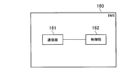
- FIG. 3 is a diagram illustrating the EMS 160 according to the embodiment.
- FIG. 4 is a diagram illustrating an example of a predetermined message according to the embodiment.
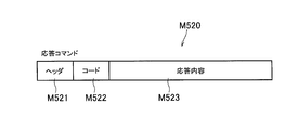
- FIG. 5 is a diagram illustrating an example of a predetermined message according to the embodiment.
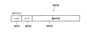
- FIG. 6 is a diagram illustrating an example of a predetermined message according to the embodiment.
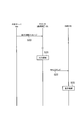
- FIG. 7 is a sequence diagram illustrating the power management method according to the embodiment.
- FIG. 8 is a sequence diagram illustrating the power management method according to the embodiment.
- a power conversion device includes a first communication unit that receives an output suppression message that instructs output suppression of a distributed power supply from an external server, a power management device that manages the power of a device provided in a customer facility, A second communication unit that performs communication of a predetermined message having a predetermined format, the predetermined format includes an information element that can store output suppression information related to output suppression of the distributed power supply, and the second communication unit includes: The predetermined message including output suppression information as an information element is transmitted to the power management apparatus.
- the second communication unit transmits a predetermined message including the output suppression information as an information element to the power management apparatus. Therefore, the power management apparatus can grasp the state of output suppression of the distributed power supply accompanying the control according to the output suppression message.
- the power management system 1 includes a customer facility 100 and an external server 400.
- the customer facility 100 has a router 200.
- the router 200 is connected to the external server 400 via the network 300.
- the router 200 forms a local area network and is connected to each device (for example, the communication device 132 of the PCS 130, the load 150, the EMS 160, the display device 170, etc.).
- a solid line indicates a power line
- a dotted line indicates a signal line. Note that the present invention is not limited to this, and a signal may be transmitted through a power line.
- the customer facility 100 includes a solar battery 110, a storage battery 120, a PCS 130, a distribution board 140, a load 150, an EMS 160, and a display device 170.
- the solar cell 110 is a device that generates power in response to light reception.
- the solar cell 110 outputs the generated DC power.
- the amount of power generated by the solar cell 110 changes according to the amount of solar radiation irradiated on the solar cell 110.
- the solar cell 110 is an example of a distributed power source that should operate in accordance with a message for instructing output suppression of the distributed power source (hereinafter, output suppression message).
- the suppression of the output of the distributed power supply is to reduce the amount of power that flows backward to the grid out of the power generated by the distributed power supply. Reducing the amount of power for reverse flow includes making the amount of power for reverse flow zero. By reducing the amount of reverse flow power, for example, the system can be stabilized.
- the suppression of the output of the distributed power source includes reducing the output (power generation or discharge) of the distributed power source regardless of the presence or absence of reverse power flow. Thereby, for example, it is possible to contribute to an increase in the amount of electricity purchased in the customer facility, or to reduce the amount of gas purchased when the distributed power source is a fuel cell.
- Storage battery 120 is a device that stores electric power.
- the storage battery 120 outputs the accumulated DC power.
- the embodiment exemplifies a case where the storage battery 120 may not operate according to the output suppression message.
- the PCS 130 is an example of a power converter (PCS; Power Conditioning System) that converts DC power into AC power.
- the PCS 130 includes a conversion device 131 and a communication device 132.
- the conversion device 131 converts the DC power input from the solar battery 110 into AC power, and converts the DC power input from the storage battery 120 into AC power. Furthermore, the converter 131 converts AC power supplied from the power system 10 into DC power.
- the converter 131 is connected to the main power line 10L (here, the main power line 10LA and the main power line 10LB) connected to the power system 10 via the first distribution board 140A, and both the solar battery 110 and the storage battery 120 are connected. Connected to.
- the main power line 10LA is a power line that connects the power system 10 and the first distribution board 140A
- the main power line 10LB is a power line that connects the first distribution board 140A and the second distribution board 140B.
- the communication device 132 is connected to the conversion device 131, receives various messages to the conversion device 131, and transmits various messages from the conversion device 131.
- a protocol for example, a unique protocol
- PCS 130 In communication between the communication device 132 and the conversion device 131, a protocol (for example, a unique protocol) applied to the PCS 130 is used.
- the communication device 132 is connected to the external server 400 via the router 200, and receives an output suppression message from the router 200 instructing to suppress the output of the distributed power supply.
- the communication device 131 and the external server 400 may communicate via a dedicated line, or may communicate via a public communication line such as the Internet, for example.
- the communication device 132 is connected to the EMS 160 via the router 200, and performs communication of a predetermined message having a predetermined format with the EMS 160.
- the predetermined format is not particularly limited, and for example, the ECHONET Lite system, the SEP2.0 system, the KNX system, or the like can be used.
- the predetermined format is a format that conforms to the ECHONET Lite system.
- the predetermined message may be a command that can include output suppression information related to output suppression.
- the predetermined message is, for example, a SET command, a GET command, a response command to the GET command, or an INF command.
- the SET command is a message for instructing settings and operations for the PCS 130.
- the GET command is a message for acquiring the state of the PCS 130.
- the response command is a message including information requested by the GET command.
- the INF command is a message for notifying the state of the PCS 130.
- the GET command is an example of a transmission request message for requesting transmission of a message from the PCS 130 to the EMS 160.
- the distribution board 140 is connected to the main power line 10L.
- the distribution board 140 includes a first distribution board 140A and a second distribution board 140B.
- the first distribution board 140A is connected to the power system 10 via the main power line 10LA and is connected to the solar battery 110 and the storage battery 120 via the converter 131. Further, the first distribution board 140A controls the power output from the converter 131 and the power supplied from the power system 10 to flow to the main power line 10LB.
- the power flowing from the main power line 10LB is distributed to each device (here, the load 150 and the EMS 160) by the second distribution board 140B.
- the load 150 is a device that consumes power supplied through the power line.
- the load 150 includes devices such as a refrigerator, lighting, an air conditioner, and a television.
- the load 150 may be a single device or may include a plurality of devices.
- the EMS 160 is an apparatus (EMS; Energy Management System) that manages power information indicating power in the customer facility 100.
- the power in the customer facility 100 refers to power flowing through the customer facility 100, power purchased by the customer facility 100, power sold from the customer facility 100, and the like.
- the EMS 160 may control the power generation amount of the solar battery 110, the charge amount of the storage battery 120, and the discharge amount of the storage battery 120.
- the EMS 160 may be configured integrally with the distribution board 140 or the PCS 130.
- the EMS 160 is a device connected to the network 300, and the function of the EMS 160 may be provided by a cloud service via the network 300.
- the EMS 160 is connected to each device (for example, the communication device 132 and the load 150 of the PCS 130) via the router 200, and performs communication of a predetermined message having a predetermined format with each device.
- the EMS 160 is connected to the display device 170 via the router 200 and communicates with the display device 170.
- the EMS 160 may perform communication of a predetermined message having a predetermined format with the display device 170.
- the predetermined format is, for example, a format that conforms to the ECHONET Lite system.
- the display device 170 displays power information indicating the power in the customer facility 100.
- the display device 170 is, for example, a smartphone, a tablet, a digital television, or a dedicated terminal.
- the display device 170 is connected to the EMS 160 by wire or wireless and communicates with the EMS 160.
- the display device 170 may perform communication of a predetermined message having a predetermined format with the EMS 160.
- the display device 170 receives data necessary for displaying power information from the EMS 160.
- the communication device 132 is connected to the external server 400 by the network 300 via the router 200.
- the communication device 132 and the router 200, and the router 200 and the communication device 132 are connected by wire or wireless.
- the network 300 is a communication network that connects the EMS 160 and the external server 400.
- the network 300 may be the Internet.
- the network 300 may include a mobile communication network.
- the network 300 may be a dedicated communication line or a general communication line. For example, when the output of the solar battery 110 is greater than or equal to a predetermined output, the output can be more reliably suppressed by using a dedicated communication line as the network 300.
- External server 400 transmits an output suppression message instructing output suppression of the distributed power supply.
- the external server 400 may transmit a message (DR; Demand Response) instructing suppression of power flow from the power system 10.
- DR Demand Response
- the output suppression message includes a target output suppression level indicating the level of output suppression of the distributed power supply (in this case, the solar battery 110).
- the target output suppression level is determined in accordance with an output (hereinafter, equipment certified output) that has been certified as an output capability (for example, a rated output) of the PCS that controls the distributed power supply.
- the target output suppression level may be expressed by an absolute value (for example, XX kW) determined according to the facility certified output, or may be expressed by a relative value (for example, a decrease in XX kW) with respect to the facility certified output.
- a suppression ratio for example, OO%) with respect to the equipment certified output.
- equipment authorization capacity [kWh] may be sufficient.
- the equipment certified output is the smaller output capability of these output capabilities.
- the facility authorization output is the sum of the output capacities of the plurality of PCSs.
- the output suppression message includes calendar information indicating a schedule of output suppression of the distributed power supply.
- the schedule for suppressing the output of the distributed power supply can be set in units of 30 minutes.
- the calendar information may include a schedule for one day, a schedule for January, or a schedule for one year.
- a predetermined period may be set as the maximum period during which the output of the distributed power source is suppressed.
- the predetermined time may be, for example, the number of days in one year (days rule) or the accumulated time in one year (cumulative time rule). More specifically, for example, the predetermined period may be 30 days in one year (30 day rule), or 360 hours in one year (360 hour rule). However, the predetermined period may not be determined (specified rule).
- the communication device 132 includes a first communication unit 132A, a second communication unit 132B, an interface 132C, and a control unit 132D.
- the first communication unit 132A receives from the external server 400 an output suppression message that instructs output suppression of the distributed power supply.
- the first communication unit 132A may receive the output suppression message from the external server 400 without going through the EMS 160.
- the second communication unit 132B performs communication of a predetermined message having a predetermined format with the EMS 160.
- the predetermined format is, for example, a format that conforms to the ECHONET Lite system.
- the predetermined format used in communication between the communication device 132 (second communication unit 132B) and the EMS 160 may be different from the format used in communication between the communication device 132 (first communication unit 132A) and the external server 400. Good.
- the predetermined format used for communication between the second communication unit 132B (second communication unit 132B) and the EMS 160 may be different from the format used for communication between the communication device 132 (interface 132C) and the conversion device 131.
- the predetermined format includes an information element that can store output suppression information related to output suppression of the distributed power supply.
- the second communication unit 132B transmits a predetermined message including the output suppression information as an information element to the EMS 160.
- the transmission from the second communication unit 132B to the EMS 160 may be one-to-one communication (unicast) or may be broadcast simultaneously (multicast).
- the second communication unit 132B receives a transmission request message (GET command) requesting transmission of a message to the EMS 160 from the EMS 160 as a predetermined message.
- the second communication unit 132B may transmit a predetermined message (INF command) including output suppression information as an information element to the EMS 160 without depending on the transmission request message (GET command).
- the second communication unit 132B may transmit a predetermined message (response command) including output suppression information as an information element to the EMS 160 in response to a transmission request message (GET command).
- the second communication unit 132B may periodically transmit a predetermined message to the EMS 160. Specifically, the periodic transmission is performed at predetermined intervals such as 30 minutes, 1 hour, or 1 day. Without being limited thereto, the second communication unit 132B may transmit a predetermined message when the predetermined format is connected to the network, activated, or restarted.
- the timing at which the second communication unit 132B transmits the predetermined message to the EMS 160 is within a predetermined time (for example, 5 minutes, 1 hour, etc.) after the first communication unit 132A receives the output suppression message from the external server 400. It may be when the state change is recognized. When the state change is recognized, for example, it may correspond to a state change announcement in the ECHONET Lite standard. More specifically, when a predetermined value (for example, a value related to output suppression) changes, a predetermined message may be broadcast simultaneously, or may be broadcast simultaneously within a predetermined domain.
- a predetermined time for example, 5 minutes, 1 hour, etc.
- a predetermined time before the content of the output suppression message is actually executed for example, 30 Minutes, 1 hour ago, etc.
- a predetermined message may be acquired from the second communication unit 132B using a transmission request message from the EMS 160 according to the date and time. Since the next update date and time may be included in the output suppression information, the EMS 160 can know the date and time when the output suppression information was updated.
- the second communication unit 132B transmits the predetermined message to the EMS 160, it may be transmitted to the external server 400 together. Transmission to the external server 400 may be performed simultaneously or at a time difference. By transmitting to the external server 400 in this way, the external server 400 can confirm the identity between the output suppression message transmitted by the external server 400 and the predetermined message.
- the output suppression information includes at least one information piece among a plurality of information pieces (A) to (F) described below. Since the output suppression information includes two or more pieces of information, the EMS 160 can grasp the state of the PCS 130 in more detail. In addition, the following information pieces are not limited to being included as output suppression information, and may be included as information elements.
- the output suppression information includes information for specifying a period during which output of the distributed power source is suppressed.
- the output suppression information may include a start time for starting output suppression of the distributed power source and an end time for ending output suppression of the distributed power source.
- the output suppression information may include a start time for starting output suppression of the distributed power supply and a duration for continuing output suppression of the distributed power supply.
- the output suppression information may be information indicating whether or not the transmission timing (current time) of the predetermined message is within the period during which the output of the distributed power source is suppressed.
- the communication device 132 may be able to specify a period during which output of the distributed power source is suppressed based on calendar information included in the output suppression message described above.
- the output suppression information includes information indicating whether or not the output of the distributed power source is actually suppressed according to the output suppression message.
- Information indicating whether or not the output of the distributed power supply is actually suppressed includes whether or not the output is being suppressed or whether the output of the distributed power supply such as the cumulative amount of output suppression is actually suppressed. Any information that can be directly or indirectly known.
- the output suppression information is information indicating that the output suppression is not actually performed although it is in the output suppression implementation time zone. May be included.
- the PCS 130 is a multi-PCS that controls the outputs of the solar battery 110 and the storage battery 120. Therefore, in the case where control is performed to charge the storage battery 120 with the generated power of the solar battery 110 without increasing the output of the PCS 130, a case where the output of the PCS 130 is equal to or lower than the target output suppression level is also assumed. Even in such a case, the output of the solar cell 110 may not be actually suppressed.
- the control for charging the storage battery 120 with the electric power generated by the solar cell 110 is performed. It includes information on whether or not the battery 110 is charging the storage battery 120 with power to be suppressed.
- the output suppression information is information that the solar battery 110 charges the storage battery 120 with power to be output suppressed, information that is scheduled to be charged, information that is not charged, information that is not scheduled to be charged, It includes information that is scheduled to stop charging, information about charging power, or information about the amount of charging power.
- the output suppression information is transmitted from the communication device 132 (second communication unit 132B) to the EMS 160, information regarding the storage capacity of the storage battery 120 may be transmitted together.
- the information related to the storage capacity includes, for example, the current storage capacity or the chargeable capacity.
- the output suppression information includes information for specifying the amount of output suppression of the distributed power source (hereinafter referred to as the suppression amount).
- the information for specifying the suppression amount may be represented by a relative value (for example, suppression of OO kW) with respect to the equipment authorized output, and a suppression ratio (for example, OO%) with respect to the equipment authorized output. It may be represented by Alternatively, the information for specifying the suppression amount may be expressed by a relative value (for example, suppression of OO kW) with respect to the maximum power generation amount, and expressed by a suppression ratio (for example, OO%) with respect to the maximum power generation amount. May be.
- the maximum power generation amount means the power generation amount that can be output by the distributed power source unless the output suppression of the distributed power source is performed according to the output suppression message.
- MPPT Maximum Power Point Tracking
- the output suppression information includes information indicating whether or not the output level of the distributed power source has reached the target output suppression level.
- the speed at which the output of the distributed power source is suppressed is determined in advance, even if the output suppression of the distributed power source is started, the output level of the distributed power source does not immediately reach the target output suppression level.
- the output suppression information includes information indicating the target output suppression level indicating the level of output suppression of the distributed power source.
- the target output level may be included in the output suppression message.
- the output suppression information includes calendar information indicating a schedule of output suppression by the distributed power source.
- the interface 132C is an interface with the conversion device 131.
- the interface 132C may be a wired interface or a wireless interface.
- a protocol for example, a unique protocol applied to the PCS 130 is used.
- the control unit 132D includes a memory and a CPU, and controls the communication device 132.
- the control unit 132D controls the output of the distributed power source according to the output suppression message by controlling the conversion device 131 using the interface 132C.
- Control part 132D acquires the state (For example, the electric power generation amount of the solar cell 110, the electrical storage amount of the storage battery 120, the discharge amount of the storage battery 120) from the conversion device 131 using the interface 132C.
- the control unit 132D generates a command for controlling the conversion device 131 based on a predetermined message received from the EMS 160, and outputs the generated command to the conversion device 131 using the interface 132C.
- the EMS 160 includes a communication unit 161 and a control unit 162.
- the communication unit 161 performs communication of a predetermined message having a predetermined format with the communication device 132.
- the predetermined format is, for example, a format that conforms to the ECHONET Lite system.
- the control unit 162 includes a memory and a CPU, and controls the EMS 160.
- the controller 162 may control the power generation amount of the solar battery 110, the charge amount of the storage battery 120, and the discharge amount of the storage battery 120.
- control unit 162 controls the display device 170 so as to display power information indicating the power in the customer facility 100.
- the control unit 162 performs display control of information related to output suppression of the distributed power supply according to a predetermined message including output suppression information as an information element.
- the control unit 162 performs at least one display control among a plurality of display controls (A) to (F) described below.
- the control unit 162 displays information for specifying the period for performing the output suppression of the distributed power supply. Take control.
- the control unit 162 displays information indicating whether or not the output is actually suppressed. Control.
- the control unit 162 performs control to display information for specifying the suppression amount.
- the control unit 162 determines that the output level of the distributed power source has reached the target output suppression level. The control which displays the information which shows whether or not is carried out is performed.
- the control unit 162 displays various information (information for specifying a period during which output suppression is performed, “output is being suppressed” Column, information for specifying the suppression amount) is displayed in the first mode (for example, blinking).
- the control unit 162 displays various information (information for specifying a period during which output suppression is performed, a character string “output is being suppressed”, Information for specifying the suppression amount) is displayed in the second mode (for example, lighting).
- the second mode is different from the first mode.
- the first mode and the second mode may be the same mode (for example, only one of blinking or lighting).
- the control unit 162 performs control to display the target output suppression level.
- control unit 162 performs control to display the calendar information.
- the GET command M510 includes a header M511, a code M512, and a target property M513.
- the GET command M510 is an example of a transmission request message for requesting transmission of a message to the EMS 160, and is an example of a message transmitted from the EMS 160 to the communication device 132.
- the header M511 is information indicating the destination of the GET command M510.
- the code M512 is information indicating the type of message including the code M512.
- the code M512 is information indicating that the message including the code M512 is a GET command.
- the target property M513 is information indicating the target content that the EMS 160 wants to know.
- the target property M513 is an information element that can store information for requesting transmission of output suppression information.
- the response command M520 includes a header M521, a code M522, and a response content M523.
- the response command is an example of a predetermined message including output suppression information as an information element, and is transmitted from the communication device 132 to the EMS 160 in response to a transmission request message (GET command).
- GET command a transmission request message
- the header M521 is information indicating the destination of the response command M520.
- the code M522 is information indicating the type of message including the code M522.
- the code M522 is information indicating that the message including the code M522 is a response command.
- the response content M523 is information indicating the content requested by the GET command.
- the response content M523 is an information element that can store output suppression information.
- the INF command M530 includes a header M531, a code M532, and a notification content M533.
- the INF command is an example of a predetermined message including output suppression information as an information element, and is transmitted from the communication device 132 to the EMS 160 without depending on the transmission request message (GET command).
- the header M531 is information indicating the destination of the INF command M530.
- the code M532 is information indicating the type of message including the code M532.
- the code M532 is information indicating that the message including the code M532 is an INF command.
- the notification content M533 is information indicating the content notified to the EMS 160.
- the notification content M533 is an information element that can store output suppression information.
- step S ⁇ b> 10 the communication device 132 receives an output suppression message from the external server 400 without going through the EMS 160.
- step S11 the communication device 132 performs output suppression of the distributed power source according to the output suppression message.
- step S12 the EMS 160 transmits a GET command to the communication device 132.
- the EMS 160 may periodically transmit a GET command to the communication device 132.
- the GET command includes information requesting transmission of output suppression information as an information element.
- step S13 the communication device 132 transmits a response command to the EMS 160 in response to the GET command.
- the response command is a predetermined message including output suppression information as an information element.
- step S14 the EMS 160 performs display control of information related to output suppression of the distributed power supply according to the response command.
- the predetermined message including the output suppression information as an information element is a response command transmitted without depending on the GET command.
- step S20 the communication device 132 receives an output suppression message from the external server 400 without going through the EMS 160.
- step S21 the communication device 132 suppresses the output of the distributed power source according to the output suppression message.
- step S22 the communication device 132 transmits an INF command to the EMS 160 without depending on the GET command.
- the communication device 132 may periodically transmit the INF command during the period in which the output of the distributed power supply is suppressed.
- the INF command is a predetermined message including output suppression information as an information element.
- step S23 the EMS 160 performs display control of information related to output suppression of the distributed power supply according to the INF command.
- the communication device 132 transmits a predetermined message including the output suppression information as an information element to the EMS 160. Therefore, the EMS 160 can grasp the state of output suppression of the distributed power supply accompanying the control according to the output suppression message.
- the solar battery 110 is illustrated as a distributed power source that should operate according to the output suppression message.
- the distributed power source is not limited to this.
- the distributed power source may be a device that generates electric power using natural energy such as wind power or geothermal heat.
- the distributed power source may be a fuel cell that generates electric power using fuel gas.
- the predetermined format used in communication between the communication device 132 and the EMS 160 is a format conforming to the ECHONET Lite system.
- the predetermined format may be a format standardized as a format used in the customer facility 100.
- the conversion device 131 and the communication device 132 are provided separately, but the embodiment is not limited to this.
- a function of the communication device 132 may be provided in the conversion device 131.
- the PCS 130 (multi-PCS) that controls the outputs of the solar battery 110 and the storage battery 120 is exemplified.
- the PCS 130 may be a device that controls only the output of at least one of the solar cell 110, the storage battery 120, and the fuel cell.
- the second communication unit 132B transmits a predetermined message including the output suppression information as an information element to the EMS 160
- the authentication information of the PCS 130 may be transmitted together.
- information for example, ID
- a specific password for example, a password for identifying an individual of the PCS 130, a specific password, and the like are assumed. By transmitting authentication information together, security can be improved.
- first communication unit 132A and the second communication unit 132B are separate members
- first communication unit 132A and the second communication unit 132B may be integrated. That is, the first communication unit 132A may also serve as the second communication unit 132B.
- the output suppression of the distributed power source described above is performed by the PCS 130. Therefore, the output suppression of the distributed power supply may be considered as the output suppression of the PCS 130.
Abstract
Description
近年では、需要家施設における電力を示す電力情報を管理する電力管理装置(EMS:Energy Management System)が注目を浴びている。しかしながら、出力抑制メッセージは、電力管理装置を経由せずに外部サーバから電力変換装置に送信されることが検討されており、その場合には、分散電源の出力抑制の状態を電力管理装置が把握することができない。
(電力管理システム)
以下において、実施形態に係る電力管理システムについて説明する。
以下において、実施形態に係る通信装置について説明する。図2に示すように、通信装置132は、第1通信部132Aと、第2通信部132Bと、インタフェース132Cと、制御部132Dとを有する。
以下において、実施形態に係る電力管理装置について説明する。図3に示すように、EMS160は、通信部161と、制御部162とを有する。
以下において、実施形態に係るメッセージフォーマットについて説明する。ここでは、所定フォーマットがECHONET Lite方式に準拠するフォーマットであるケースを例示する。
以下において、実施形態に係る電力管理方法について説明する。ここでは、通信装置132とEMS160との通信で用いられる所定フォーマットがECHONET Lite方式に準拠するフォーマットであるケースを例示する。
実施形態では、通信装置132は、出力抑制情報を情報要素として含む所定メッセージをEMS160に送信する。従って、出力抑制メッセージに従った制御に伴う分散電源の出力抑制の状態をEMS160が把握することができる。
本発明は上述した実施形態によって説明したが、この開示の一部をなす論述及び図面は、この発明を限定するものであると理解すべきではない。この開示から当業者には様々な代替実施形態、実施例及び運用技術が明らかとなろう。
Claims (14)
- 分散電源の出力抑制を指示する出力抑制メッセージを外部サーバから受信する第1通信部と、
需要家施設の電力情報を管理する電力管理装置と所定フォーマットを有する所定メッセージの通信を行う第2通信部とを備え、
前記所定フォーマットは、前記分散電源の出力抑制に関する出力抑制情報を格納可能な情報要素を含み、
前記第2通信部は、前記出力抑制情報を情報要素として含む前記所定メッセージを前記電力管理装置に送信する、電力変換装置。 - 前記出力抑制情報は、前記分散電源の出力抑制を行う期間を特定するための情報を含む、請求項1に記載の電力変換装置。
- 前記出力抑制情報は、前記出力抑制メッセージに従って前記分散電源の出力が実際に抑制されているか否かを示す情報を含む、請求項1又は請求項2に記載の電力変換装置。
- 前記出力抑制情報は、前記分散電源の出力抑制の量を特定するための情報を含む、請求項1乃至請求項3のいずれかに記載の電力変換装置。
- 前記出力抑制メッセージは、前記分散電源の出力抑制のレベルを示す目標出力抑制レベルを含み、
前記出力抑制情報は、前記分散電源の出力が前記目標出力抑制レベルに達しているか否かを示す情報を含む、請求項1乃至請求項4のいずれかに記載の電力変換装置。 - 前記出力抑制情報は、前記分散電源の出力抑制のレベルを示す目標出力抑制レベルを示す情報を含む、請求項1乃至請求項5のいずれかに記載の電力変換装置。
- 前記出力抑制情報は、前記分散電源が出力抑制のスケジュールを示すカレンダー情報を含む、請求項1乃至請求項6のいずれかに記載の電力変換装置。
- 前記第2通信部は、前記所定メッセージとして前記電力管理装置に対するメッセージの送信を要求する送信要求メッセージを前記電力管理装置から受信する、請求項1乃至請求項7のいずれかに記載の電力変換装置。
- 前記第2通信部は、前記送信要求メッセージに依存せずに、前記出力抑制情報を情報要素として含む前記所定メッセージを前記電力管理装置に送信する、請求項8に記載の電力変換装置。
- 前記第2通信部は、前記送信要求メッセージに応じて、前記出力抑制情報を情報要素として含む前記所定メッセージを前記電力管理装置に送信する、請求項8に記載の電力変換装置。
- 前記第2通信部と前記電力変換装置との通信で用いられる前記所定フォーマットは、前記第1通信部と前記外部サーバとの通信で用いられるフォーマットと異なる、請求項1乃至請求項10のいずれかに記載の電力変換装置。
- 前記分散電源は、太陽電池及び蓄電池の両方を少なくとも含み、
前記太陽電池で発電された電力は、前記蓄電池に充電可能であり、
前記情報要素は、前記太陽電池で発電された電力を前記蓄電池に充電させているか否かの情報を含む、請求項1乃至請求項11のいずれかに記載の電力変換装置。 - 需要家施設における電力を示す電力情報を表示するように表示装置を制御する制御部と、
分散電源の出力抑制を指示する出力抑制メッセージを外部サーバから受信する電力変換装置と所定フォーマットを有する所定メッセージの通信を行う通信部とを備え、
前記所定フォーマットは、前記分散電源の出力抑制に関する出力抑制情報を格納可能な情報要素を含み、
前記通信部は、前記出力抑制情報を情報要素として含む前記所定メッセージを前記電力変換装置から受信し、
前記制御部は、前記出力抑制情報を情報要素として含む前記所定メッセージに応じて、前記分散電源の出力抑制に関する情報の表示制御を行う、電力管理装置。 - 需要家施設における電力を示す電力情報を管理する電力管理装置と所定フォーマットを有する所定メッセージの通信を行う電力変換装置が、分散電源の出力抑制を指示する出力抑制メッセージを外部サーバから受信するステップと、
前記電力変換装置が、前記所定フォーマットに含まれる情報要素として前記分散電源の出力抑制に関する出力抑制情報を含む前記所定メッセージを前記電力管理装置に送信するステップとを備える、電力管理方法。
Priority Applications (3)
| Application Number | Priority Date | Filing Date | Title |
|---|---|---|---|
| US15/580,466 US10381832B2 (en) | 2015-06-08 | 2016-06-08 | Power conversion apparatus, power management apparatus, and power management method |
| EP16807520.8A EP3306771B1 (en) | 2015-06-08 | 2016-06-08 | Electric power conversion device, electric power management device, and electric power management method |
| JP2016554758A JP6069597B1 (ja) | 2015-06-08 | 2016-06-08 | 電力変換装置、電力管理装置及び電力管理方法 |
Applications Claiming Priority (2)
| Application Number | Priority Date | Filing Date | Title |
|---|---|---|---|
| JP2015-115846 | 2015-06-08 | ||
| JP2015115846 | 2015-06-08 |
Publications (1)
| Publication Number | Publication Date |
|---|---|
| WO2016199814A1 true WO2016199814A1 (ja) | 2016-12-15 |
Family
ID=57503822
Family Applications (1)
| Application Number | Title | Priority Date | Filing Date |
|---|---|---|---|
| PCT/JP2016/067074 WO2016199814A1 (ja) | 2015-06-08 | 2016-06-08 | 電力変換装置、電力管理装置及び電力管理方法 |
Country Status (4)
| Country | Link |
|---|---|
| US (1) | US10381832B2 (ja) |
| EP (1) | EP3306771B1 (ja) |
| JP (2) | JP6069597B1 (ja) |
| WO (1) | WO2016199814A1 (ja) |
Cited By (4)
| Publication number | Priority date | Publication date | Assignee | Title |
|---|---|---|---|---|
| JP2017108625A (ja) * | 2015-06-08 | 2017-06-15 | 京セラ株式会社 | 電力変換装置、電力管理装置及び電力管理方法 |
| JPWO2017169585A1 (ja) * | 2016-03-29 | 2019-02-07 | 京セラ株式会社 | 管理システム、管理方法、電力変換装置及び管理装置 |
| WO2019111741A1 (ja) * | 2017-12-08 | 2019-06-13 | 京セラ株式会社 | 電力管理サーバ及び電力管理方法 |
| JP2020120478A (ja) * | 2019-01-22 | 2020-08-06 | パナソニックIpマネジメント株式会社 | 制御システム、電力変換システム、制御方法、プログラム |
Families Citing this family (4)
| Publication number | Priority date | Publication date | Assignee | Title |
|---|---|---|---|---|
| WO2017130307A1 (ja) * | 2016-01-27 | 2017-08-03 | 三菱電機株式会社 | 管理装置、及び、制御方法 |
| JP7075930B2 (ja) * | 2017-06-09 | 2022-05-26 | シャープ株式会社 | 制御システムおよび外部連携装置 |
| US11379937B2 (en) * | 2017-11-29 | 2022-07-05 | Kyocera Corporation | Power management server and power management method |
| US11677264B2 (en) | 2020-11-09 | 2023-06-13 | Electronic Power Design, Inc. | System and method for a backup power supply |
Citations (2)
| Publication number | Priority date | Publication date | Assignee | Title |
|---|---|---|---|---|
| WO2012144044A1 (ja) * | 2011-04-21 | 2012-10-26 | 株式会社日立製作所 | 電力管理システム及び方法 |
| JP2013031266A (ja) * | 2011-07-27 | 2013-02-07 | Kyocera Corp | 電力管理システム |
Family Cites Families (44)
| Publication number | Priority date | Publication date | Assignee | Title |
|---|---|---|---|---|
| JP4213941B2 (ja) * | 2002-10-11 | 2009-01-28 | シャープ株式会社 | 複数の分散電源の出力抑制方法および分散電源管理システム |
| EP1682832B1 (en) * | 2003-10-15 | 2009-06-17 | Ice Energy, Inc. | Refrigeration apparatus |
| US8234876B2 (en) | 2003-10-15 | 2012-08-07 | Ice Energy, Inc. | Utility managed virtual power plant utilizing aggregated thermal energy storage |
| US8855829B2 (en) | 2007-01-03 | 2014-10-07 | Gridpoint, Inc. | Method for controlling energy resources |
| US9318917B2 (en) * | 2009-04-09 | 2016-04-19 | Sony Corporation | Electric storage apparatus and power control system |
| US8509954B2 (en) | 2009-08-21 | 2013-08-13 | Allure Energy, Inc. | Energy management system and method |
| MX2012000906A (es) * | 2009-07-20 | 2012-09-07 | Allure Energy Inc | Sistema y metodo de gestion de energia. |
| JP2011130597A (ja) | 2009-12-18 | 2011-06-30 | Sony Corp | 電力制御方法、通信装置および電力制御システム |
| JP5372724B2 (ja) * | 2009-12-21 | 2013-12-18 | 株式会社日立製作所 | 自然エネルギを用いた発電システム |
| KR101736900B1 (ko) | 2010-09-29 | 2017-05-17 | 삼성전자주식회사 | 전기기기, 그를 가지는 전력 관리 시스템 및 그 제어 방법 |
| KR101729019B1 (ko) | 2010-10-12 | 2017-04-21 | 삼성전자주식회사 | 전력 관리 장치, 그를 가지는 전력 관리 시스템 및 그 제어 방법 |
| JP5580183B2 (ja) | 2010-12-13 | 2014-08-27 | パナソニック株式会社 | 電力制御装置及びそれを用いた電力制御システム |
| JP5259763B2 (ja) | 2011-03-25 | 2013-08-07 | 株式会社東芝 | 電力管理装置、システム及び方法 |
| JP5677161B2 (ja) | 2011-03-28 | 2015-02-25 | 株式会社東芝 | 充放電判定装置及びプログラム |
| EP2763278B1 (en) | 2011-09-26 | 2019-12-11 | Kyocera Corporation | Energy management system, energy management method and host energy management device |
| JP5731941B2 (ja) * | 2011-09-30 | 2015-06-10 | 株式会社東芝 | 充放電指示装置、充放電指示方法、及び充放電指示プログラム |
| WO2013088584A1 (ja) * | 2011-12-14 | 2013-06-20 | 京セラ株式会社 | 表示端末、電力制御システム、および表示方法 |
| JP6145669B2 (ja) * | 2012-03-27 | 2017-06-14 | パナソニックIpマネジメント株式会社 | 電力管理装置および電力管理システム |
| JP5980536B2 (ja) | 2012-03-27 | 2016-08-31 | シャープ株式会社 | 発電システム、並びに当該発電システムに用いるパワーコンディショナおよび出力抑制管理装置 |
| JP5606484B2 (ja) | 2012-03-29 | 2014-10-15 | 株式会社東芝 | 充放電制御装置、充放電制御システム及び充放電制御プログラム |
| US9461471B2 (en) | 2012-06-20 | 2016-10-04 | Causam Energy, Inc | System and methods for actively managing electric power over an electric power grid and providing revenue grade date usable for settlement |
| US9563215B2 (en) | 2012-07-14 | 2017-02-07 | Causam Energy, Inc. | Method and apparatus for actively managing electric power supply for an electric power grid |
| US8849715B2 (en) | 2012-10-24 | 2014-09-30 | Causam Energy, Inc. | System, method, and apparatus for settlement for participation in an electric power grid |
| US9513648B2 (en) | 2012-07-31 | 2016-12-06 | Causam Energy, Inc. | System, method, and apparatus for electric power grid and network management of grid elements |
| JP5675727B2 (ja) | 2012-08-10 | 2015-02-25 | 株式会社東芝 | 充放電指示装置、プログラム |
| JP2014096866A (ja) * | 2012-11-07 | 2014-05-22 | Toshiba Corp | エネルギー管理システム、エネルギー管理方法、プログラムおよびサーバ装置 |
| EP2894747A4 (en) | 2012-09-03 | 2016-04-06 | Toshiba Kk | ENERGY CONTROL SYSTEM, SERVER, ENERGY CONTROL METHOD AND STORAGE MEDIUM |
| JP5921390B2 (ja) * | 2012-09-03 | 2016-05-24 | 株式会社東芝 | エネルギー管理システム、エネルギー管理方法、プログラムおよびサーバ装置 |
| JP5680038B2 (ja) * | 2012-09-18 | 2015-03-04 | 株式会社東芝 | 電力変換装置、協調制御方法、協調制御システムおよびプログラム |
| JP2014064425A (ja) | 2012-09-24 | 2014-04-10 | Toshiba Corp | 電力変換装置及びプログラム |
| JP6081125B2 (ja) * | 2012-10-09 | 2017-02-15 | 株式会社日立製作所 | 太陽光発電装置および電力管理システム、並びに、そのための電力負荷と計測装置 |
| US9727929B2 (en) | 2012-11-21 | 2017-08-08 | Kabushiki Kaisha Toshiba | Energy management system, energy management method, program, server apparatus, and local server |
| JP6042184B2 (ja) * | 2012-11-21 | 2016-12-14 | 株式会社東芝 | エネルギー管理システム、エネルギー管理方法、プログラム、サーバ装置およびローカルサーバ |
| JP2014171359A (ja) | 2013-03-05 | 2014-09-18 | Sharp Corp | 電力変換装置 |
| JP6393461B2 (ja) * | 2013-03-19 | 2018-09-19 | 株式会社東芝 | 通信装置、電力変換装置、通信方法、プログラムおよび電力システム |
| JP6160157B2 (ja) | 2013-03-22 | 2017-07-12 | 富士通株式会社 | 電力供給システム、制御装置、制御方法および制御プログラム |
| JP6339318B2 (ja) * | 2013-04-09 | 2018-06-06 | 京セラ株式会社 | 情報機器、制御システム及び制御方法 |
| US9755430B2 (en) * | 2013-04-11 | 2017-09-05 | Solantro Semiconductor Corp. | Virtual inverter for power generation units |
| JP5964506B2 (ja) * | 2013-05-23 | 2016-08-03 | 京セラ株式会社 | 電力制御装置、電力制御方法、及び電力制御システム |
| WO2014208059A1 (ja) * | 2013-06-27 | 2014-12-31 | パナソニック株式会社 | 電力調整装置、電力調整方法、電力調整システム、蓄電装置、サーバ、プログラム |
| JP6394087B2 (ja) | 2014-03-31 | 2018-09-26 | 株式会社デンソー | エネルギー管理システム |
| JP2016059250A (ja) | 2014-09-12 | 2016-04-21 | 株式会社東芝 | 機器運転計画作成装置、機器運転計画作成方法、及び機器運転計画作成プログラム |
| EP3236554A4 (en) * | 2014-12-16 | 2018-06-20 | Sekisui Chemical Co., Ltd. | Demand power prediction device, demand power prediction method, and program |
| EP3331119B1 (en) | 2015-07-29 | 2022-02-16 | Kyocera Corporation | Management server and management method |
-
2016
- 2016-06-08 JP JP2016554758A patent/JP6069597B1/ja active Active
- 2016-06-08 EP EP16807520.8A patent/EP3306771B1/en active Active
- 2016-06-08 US US15/580,466 patent/US10381832B2/en active Active
- 2016-06-08 WO PCT/JP2016/067074 patent/WO2016199814A1/ja active Application Filing
- 2016-12-26 JP JP2016251505A patent/JP6715448B2/ja active Active
Patent Citations (2)
| Publication number | Priority date | Publication date | Assignee | Title |
|---|---|---|---|---|
| WO2012144044A1 (ja) * | 2011-04-21 | 2012-10-26 | 株式会社日立製作所 | 電力管理システム及び方法 |
| JP2013031266A (ja) * | 2011-07-27 | 2013-02-07 | Kyocera Corp | 電力管理システム |
Non-Patent Citations (1)
| Title |
|---|
| See also references of EP3306771A4 * |
Cited By (7)
| Publication number | Priority date | Publication date | Assignee | Title |
|---|---|---|---|---|
| JP2017108625A (ja) * | 2015-06-08 | 2017-06-15 | 京セラ株式会社 | 電力変換装置、電力管理装置及び電力管理方法 |
| JPWO2017169585A1 (ja) * | 2016-03-29 | 2019-02-07 | 京セラ株式会社 | 管理システム、管理方法、電力変換装置及び管理装置 |
| WO2019111741A1 (ja) * | 2017-12-08 | 2019-06-13 | 京セラ株式会社 | 電力管理サーバ及び電力管理方法 |
| JPWO2019111741A1 (ja) * | 2017-12-08 | 2020-12-03 | 京セラ株式会社 | 電力管理サーバ及び電力管理方法 |
| US11870268B2 (en) | 2017-12-08 | 2024-01-09 | Kyocera Corporation | Power management server and power management method |
| JP2020120478A (ja) * | 2019-01-22 | 2020-08-06 | パナソニックIpマネジメント株式会社 | 制御システム、電力変換システム、制御方法、プログラム |
| JP7129661B2 (ja) | 2019-01-22 | 2022-09-02 | パナソニックIpマネジメント株式会社 | 制御システム、電力変換システム、制御方法、プログラム |
Also Published As
| Publication number | Publication date |
|---|---|
| JP6715448B2 (ja) | 2020-07-01 |
| US10381832B2 (en) | 2019-08-13 |
| JP6069597B1 (ja) | 2017-02-01 |
| JP2017093290A (ja) | 2017-05-25 |
| JPWO2016199814A1 (ja) | 2017-06-22 |
| EP3306771B1 (en) | 2019-11-27 |
| EP3306771A1 (en) | 2018-04-11 |
| US20180145509A1 (en) | 2018-05-24 |
| EP3306771A4 (en) | 2018-11-07 |
Similar Documents
| Publication | Publication Date | Title |
|---|---|---|
| JP6069597B1 (ja) | 電力変換装置、電力管理装置及び電力管理方法 | |
| US11056911B2 (en) | Management system, management method, equipment, and management device | |
| JP6582091B2 (ja) | 電力変換装置、電力管理装置及び電力管理方法 | |
| WO2017204011A1 (ja) | 管理システム、管理方法、電力変換装置及び管理装置 | |
| JP6366836B2 (ja) | 電力変換装置、電力管理装置及び電力管理方法 | |
| WO2018062247A1 (ja) | 電力管理方法、電力管理装置、電力変換装置及び電力管理システム | |
| JP6328216B2 (ja) | 管理システム、管理方法、機器及び管理装置 | |
| WO2017169585A1 (ja) | 管理システム、管理方法、電力変換装置及び管理装置 | |
| JP6085071B1 (ja) | 電力変換装置、電力管理装置及び電力管理方法 | |
| JP7153686B2 (ja) | 表示装置、管理装置、及び制御方法 | |
| JP2018055896A (ja) | 電力管理方法、電力管理装置、燃料電池装置及び電力管理システム |
Legal Events
| Date | Code | Title | Description |
|---|---|---|---|
| ENP | Entry into the national phase |
Ref document number: 2016554758 Country of ref document: JP Kind code of ref document: A |
|
| 121 | Ep: the epo has been informed by wipo that ep was designated in this application |
Ref document number: 16807520 Country of ref document: EP Kind code of ref document: A1 |
|
| WWE | Wipo information: entry into national phase |
Ref document number: 15580466 Country of ref document: US |
|
| NENP | Non-entry into the national phase |
Ref country code: DE |
|
| WWE | Wipo information: entry into national phase |
Ref document number: 2016807520 Country of ref document: EP |