WO2016199677A1 - ボールねじ - Google Patents
ボールねじ Download PDFInfo
- Publication number
- WO2016199677A1 WO2016199677A1 PCT/JP2016/066473 JP2016066473W WO2016199677A1 WO 2016199677 A1 WO2016199677 A1 WO 2016199677A1 JP 2016066473 W JP2016066473 W JP 2016066473W WO 2016199677 A1 WO2016199677 A1 WO 2016199677A1
- Authority
- WO
- WIPO (PCT)
- Prior art keywords
- nut
- ball screw
- flat surface
- ball
- main body
- Prior art date
- Legal status (The legal status is an assumption and is not a legal conclusion. Google has not performed a legal analysis and makes no representation as to the accuracy of the status listed.)
- Ceased
Links
Images


Classifications
-
- F—MECHANICAL ENGINEERING; LIGHTING; HEATING; WEAPONS; BLASTING
- F16—ENGINEERING ELEMENTS AND UNITS; GENERAL MEASURES FOR PRODUCING AND MAINTAINING EFFECTIVE FUNCTIONING OF MACHINES OR INSTALLATIONS; THERMAL INSULATION IN GENERAL
- F16H—GEARING
- F16H25/00—Gearings comprising primarily only cams, cam-followers and screw-and-nut mechanisms
- F16H25/18—Gearings comprising primarily only cams, cam-followers and screw-and-nut mechanisms for conveying or interconverting oscillating or reciprocating motions
- F16H25/20—Screw mechanisms
- F16H25/22—Screw mechanisms with balls, rollers, or similar members between the co-operating parts; Elements essential to the use of such members
-
- F—MECHANICAL ENGINEERING; LIGHTING; HEATING; WEAPONS; BLASTING
- F16—ENGINEERING ELEMENTS AND UNITS; GENERAL MEASURES FOR PRODUCING AND MAINTAINING EFFECTIVE FUNCTIONING OF MACHINES OR INSTALLATIONS; THERMAL INSULATION IN GENERAL
- F16H—GEARING
- F16H25/00—Gearings comprising primarily only cams, cam-followers and screw-and-nut mechanisms
- F16H25/18—Gearings comprising primarily only cams, cam-followers and screw-and-nut mechanisms for conveying or interconverting oscillating or reciprocating motions
- F16H25/20—Screw mechanisms
- F16H25/24—Elements essential to such mechanisms, e.g. screws, nuts
Definitions
- the present invention relates to a ball screw.
- the ball screw is disposed between a nut having a spiral groove formed on the inner peripheral surface, a screw shaft having a spiral groove formed on the outer peripheral surface, and a raceway formed by the spiral groove of the nut and the spiral groove of the screw shaft. And a ball return path for returning the ball from the end point of the track to the start point, and the nut moves relative to the screw shaft as the ball rolls in the track.
- a return tube method is often adopted because it is easy to assemble.
- the conventional return tube type ball screw with the recent high rotation of the ball screw, the speed at which the ball collides with the return tube increases and the collision energy increases, so that the return tube and thread groove ( (Including both shoulders of the thread groove).
- Patent Literature 1 and 2 a technology equipped with a return tube that scoops the ball in the tangential direction of the screw shaft and the lead angle direction of the screw groove is disclosed in Patent Literature 1 and 2.
- the technology disclosed in Patent Document 1 is not made of metal but made of synthetic resin in view of the complicated shape of the return tube for scooping up the ball in the tangential direction of the screw shaft and the lead angle direction of the screw groove.
- This technology uses a return tube.
- the technique disclosed in Patent Document 2 is a technique in which a through hole inclined along a spiral groove is provided in a nut, and an end portion that forms a linear shape of a return tube is inserted into the hole.
- JP 2010-38196 A Japanese Utility Model Publication No. 6-69502
- Patent Document 1 requires a mold for producing a return tube made of synthetic resin, and it is necessary to manufacture a huge amount of molds in order to meet various ball screw specifications. Arise. As a result, the manufacturing cost may increase. Further, in the technique described in Patent Document 2, in order to open an oblique hole in a nut, a general 4-axis machining center cannot be used, and expensive equipment (for example, a 5-axis machining center) is required. There are large restrictions. As a result, there is a room for improvement because there is a possibility of increasing capital investment.
- a certain aspect of the ball screw for achieving the above object includes a nut having a spiral groove formed on the inner peripheral surface, a screw shaft having a spiral groove formed on the outer peripheral surface, a spiral groove of the nut, and a spiral groove of the screw shaft.
- the circulation part is provided in a U-shaped cylindrical main body portion arranged in contact with the outer flat surface of the nut, and is inserted into a pair of circulation holes provided on the outer flat surface, each having a cylindrical shape.
- the leg portion is inserted in a direction perpendicular to the axial direction of the nut with respect to the circulation hole provided on the outer flat surface of the nut, and the main body portion is disposed in contact with the outer flat surface.
- a connecting portion between the main body portion and the leg portion may be inside the nut.
- the fitting shape which mutually fits may be formed in each edge part of the said main-body part and the said leg part.
- the circulation hole may be provided with a countersink for positioning the leg.
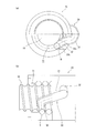
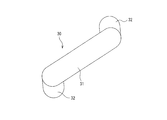
- FIG. 1 It is a top view which shows the structure in a certain aspect of a ball screw. It is a figure which shows the structure in a certain aspect of a ball screw, (a) is the fragmentary sectional view seen from the axial direction, (b) is the fragmentary sectional view seen from the side surface. It is a top view which shows the structure of the circulation component in a certain aspect with a ball screw. It is a figure which shows the structure of the circulation component in the aspect with a ball screw, (a) is sectional drawing of the main-body part along the track
- (D) is sectional drawing of the leg part along the track
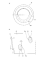
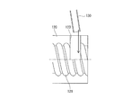
- (e) is a side view of the main-body part and leg part as a modification. It is a figure which shows the structure in a certain aspect of a ball screw, (a) is the fragmentary sectional view seen from the axial direction of the nut, (b) is a side view of a nut. It is sectional drawing which shows an example of the installation aspect of the circulation component of the conventional ball screw.
- a ball screw 1 includes a screw shaft 10 having a spiral groove 11 formed on the outer peripheral surface, a nut 20 having a spiral groove formed on the inner peripheral surface, and a rolling element.
- a ball B and a circulating component 30.
- the circulating component 30 is fixed to the nut 20 by a mounting component 40.
- the balls are disposed so as to be able to roll in a raceway formed by a spiral groove 11 of the screw shaft 10 and a spiral groove (not shown) of the nut 20 and in a ball return path formed by the circulating component 30. Yes.
- the circulating component 30 is composed of a main body 31 machined with metal (stainless steel, brass, carbon, etc.), not a synthetic resin, and a pair of parts installed at both ends thereof.
- the leg portion 32 is formed. That is, the circulating component 30 is formed by cutting a short cylindrical body at both end portions 31b and 31b of a main body portion 31 (see FIG. 4A) formed by bending a long cylindrical body into a U shape.
- the end portions 32a and 32a of the two leg portions 32 and 32 are connected.
- the leg portion 32 when the circulating component 30 is installed in the through hole 23 provided in the outer flat surface 22 of the nut 20, the leg portion 32 inserted into the through hole 23. Is inserted in the direction perpendicular to the axial direction of the nut 20 with respect to the circulation hole 23. Further, a tongue 32c for scooping up the ball B in the tangential direction is formed at the other end 32b of the leg 32.
- the lower surface (surface on the leg 32 side) 31b of the main body 31 is a surface that contacts the outer flat surface 22 of the nut 20 (see FIG. 4A). ).
- the joining mode of the main body 31 and the leg 32 is not particularly limited as long as it does not adversely affect the rolling of the ball, but as a modification, the end 32a of the leg 32 and the end of the main body 31 are used. It is good also as a shape which 31a engages.
- the end portion 32a of the leg portion 32 may be tapered, and the end portion 31a of the main body portion 31 may be reversely tapered, as shown in FIG. 4 (f).
- a convex portion may be provided at the end portion 32 a of the leg portion 32, and a concave portion may be provided at the end portion 31 a of the main body portion 31.
- connection portion joint portion between the end portion 31 a and the end portion 32 a
- the main body portion 31 and the leg portion 32 is provided. It is installed so as to be located inside the nut 20 (on the axial center side from the surface of the nut 20).
- the through hole 23 formed in the nut 20 is formed in a spiral groove (parallel to the spiral groove of the screw shaft 10) formed on the inner peripheral surface of the nut 20. It is provided with an oval opening in a direction perpendicular to the axial direction of the nut 20, not obliquely along the axis.
- the through holes 23 and 23 are seats in which the other end portion (end portion on the side where the tongue portion 32c is formed) 32b of the leg portion 32 of the circulating component 30 abuts on an edge portion other than the ball trajectory.
- the feeding portion 23a is formed in a U shape.
- the width d of the countersunk portion 23 a is substantially the same as the width d of the other leg portion 32 b of the circulating component 30. Moreover, the tongue part 32c formed in the other edge part 32b of the two leg parts 32 is each inserted in the counterbore part 23a. Thereafter, both ends of the main body 31 may be joined to one end 32 a of each leg 32 so that the circulating component 30 is installed in the through hole 23.
- the through-hole 23 is provided in the direction orthogonal to the axial direction of the nut 20, it is only necessary to open a simple slot without using an expensive machine tool. It is possible to provide a ball screw of a tangential scooping type corresponding to a wide variety of variations at low cost.
- the structure of the circulating component 30 used in the present embodiment is a structure that scoops up the ball in the tangential direction, the impact force generated when the ball hits the other end 32b of the circulating component 30 can be weakened. it can. As a result, it is effective in improving the allowable rotational speed of the ball screw 1 and reducing the operating sound of the ball screw 1.
- the circulating component 30 used in the present embodiment includes a main body 31 and a leg 32, and can be manufactured at low cost by merely machining a cylindrical member bent with a single radius of curvature. .
- the tongue 32c provided on the leg portion 32 can be processed in the same manner as a conventional circulation tube, it is not necessary to newly manufacture a cutting tool or a jig. Therefore, the manufacturing cost is not increased.
- the main body and the leg are separated, a short cylindrical body made of cold-rolled steel sheet is formed as a leg, and carburizing or carbonitriding is performed to partially improve the strength. it can.
Landscapes
- Engineering & Computer Science (AREA)
- General Engineering & Computer Science (AREA)
- Mechanical Engineering (AREA)
- Transmission Devices (AREA)
Abstract
許容回転数向上と作動音の低滅を実現するだけでなく、低コストで幅広いバリエーシヨンに対応可能なボールねじを提供する。そのために、ボールねじ(1)は、ねじ軸(10)と、ナット(20)と、ボールを軌道の終点から始点に戻す循環部品(30)とを備える。循環部品(30)は、ナット(20)の外側平坦面に接触配置されるU字状の筒形状をなす本体部(31)と、外側平坦面に設けられ、それぞれ筒形状をなす二個一組の循環孔(23)に挿入される一対の脚部(32,32)とからなる。脚部(32)は、ナット(20)の外側平坦面に設けられた循環孔(23)に対してナット(20)の軸方向に直交する方向に挿入され、本体部(31)が外側平坦面に接触配置される。
Description
本発明は、ボールねじに関する。
ボールねじは、内周面に螺旋溝が形成されたナットと、外周面に螺旋溝が形成されたねじ軸と、ナットの螺旋溝とねじ軸の螺旋溝で形成される軌道の間に配置されたボールと、ボールを軌道の終点から始点に戻すボール戻し経路とを備え、前記軌道内をボールが転動することで前記ナットがねじ軸に対して相対移動する装置である。ボールねじのボール戻し経路としては、組み立てが容易である点から、リターンチューブ方式を採用することが多い。
しかし、従来のリターンチューブ方式のボールねじでは、最近のボールねじの高回転化に伴って、ボールがリターンチューブに衝突するスピードが速くなり、衝突エネルギーが大きくなることで、リターンチューブやねじ溝(ねじ溝の両肩部などを含む)が損傷し易くなる。
しかし、従来のリターンチューブ方式のボールねじでは、最近のボールねじの高回転化に伴って、ボールがリターンチューブに衝突するスピードが速くなり、衝突エネルギーが大きくなることで、リターンチューブやねじ溝(ねじ溝の両肩部などを含む)が損傷し易くなる。
そこで、この損傷を防止し、許容回転数向上と作動音の低滅を実現するために、ねじ軸の接線方向及びねじ溝のリード角方向にボールを掬い上げるリターンチューブを備えた技術が特許文献1,2に開示されている。
特許文献1に開示された技術は、ねじ軸の接線方向及びねじ溝のリード角方向にボールを掬い上げるためにリターンチューブの形状が複雑になることに鑑み、金属製ではなく、合成樹脂製のリターンチューブを採用した技術である。
特許文献2に開示された技術は、螺旋溝に沿って傾斜させた貫通穴をナットに設け、その穴に、リターンチューブの直線形状をなす端部を挿入する構成とした技術である。
特許文献1に開示された技術は、ねじ軸の接線方向及びねじ溝のリード角方向にボールを掬い上げるためにリターンチューブの形状が複雑になることに鑑み、金属製ではなく、合成樹脂製のリターンチューブを採用した技術である。
特許文献2に開示された技術は、螺旋溝に沿って傾斜させた貫通穴をナットに設け、その穴に、リターンチューブの直線形状をなす端部を挿入する構成とした技術である。
しかしながら、特許文献1に記載の技術では、合成樹脂製のリターンチューブを作製するために金型が必要であり、種々のボールねじ仕様に対応しようとすると膨大な量の金型を製造する必要が生じる。その結果、製造コスト高を起因する可能性がある。
また、特許文献2に記載の技術では、ナットに斜めの穴を開けるためには、一般の4軸マシニングセンタなどでは対応できず、高価な設備(例えば、5軸マシニングセンタ等)が必要となり、設備上の制約が大きい。その結果、設備投資が嵩む可能性があるため、改善の余地があった。
また、特許文献2に記載の技術では、ナットに斜めの穴を開けるためには、一般の4軸マシニングセンタなどでは対応できず、高価な設備(例えば、5軸マシニングセンタ等)が必要となり、設備上の制約が大きい。その結果、設備投資が嵩む可能性があるため、改善の余地があった。
また、図6に示すように、ナット120に斜めの穴を開ける代わりに、リターンチューブ130の端部が斜めに挿入できる大きな穴123をナット120に開ける技術も考えられる。しかし、隣り合う螺旋溝121,121の間隔が狭い場合、穴123がナット120の螺旋溝に干渉してしまい、好ましくない。
そこで、本発明は上記課題に着目してなされたものであり、その目的は、許容回転数向上と作動音の低滅を実現するだけでなく、低コストで幅広いバリエーシヨンに対応可能なボールねじを提供することにある。
そこで、本発明は上記課題に着目してなされたものであり、その目的は、許容回転数向上と作動音の低滅を実現するだけでなく、低コストで幅広いバリエーシヨンに対応可能なボールねじを提供することにある。
上記目的を達成するためのボールねじのある態様は、内周面に螺旋溝が形成されたナットと、外周面に螺旋溝が形成されたねじ軸と、ナットの螺旋溝とねじ軸の螺旋溝で形成される軌道の間に配置されたボールと、ボールを軌道の終点から始点に戻すボール戻し経路を形成する循環部品とを備え、
前記循環部品は、前記ナットの外側平坦面に接触配置されるU字状の筒形状をなす本体部と、前記外側平坦面に設けられ、それぞれ筒形状をなす二個一組の循環孔に挿入される一対の脚部とからなり、
前記脚部が、前記ナットの外側平坦面に設けられた前記循環孔に対して前記ナットの軸方向に直交する方向に挿入され、前記本体部が前記外側平坦面に接触配置される。
前記循環部品は、前記ナットの外側平坦面に接触配置されるU字状の筒形状をなす本体部と、前記外側平坦面に設けられ、それぞれ筒形状をなす二個一組の循環孔に挿入される一対の脚部とからなり、
前記脚部が、前記ナットの外側平坦面に設けられた前記循環孔に対して前記ナットの軸方向に直交する方向に挿入され、前記本体部が前記外側平坦面に接触配置される。
ここで、上記ボールねじにおいては、前記本体部と前記脚部との接続部分が前記ナットの内部であるようにしてもよい。
また、上記ボールねじにおいては、前記本体部及び前記脚部のそれぞれの端部には、互いに嵌合する嵌合形状が形成されてもよい。
また、上記ボールねじにおいては、前記循環孔には、前記脚部の位置合わせのための座繰り部が設けられてもよい。
また、上記ボールねじにおいては、前記本体部及び前記脚部のそれぞれの端部には、互いに嵌合する嵌合形状が形成されてもよい。
また、上記ボールねじにおいては、前記循環孔には、前記脚部の位置合わせのための座繰り部が設けられてもよい。
本発明の一態様によれば、許容回転数向上と作動音の低滅を実現するだけでなく、低コストで幅広いバリエーシヨンに対応可能なボールねじを提供することができる。
以下、ボールねじの実施形態について図面を参照して説明する。
以下の詳細な説明では、本発明の実施形態の完全な理解を提供するように多くの特定の細部について記載される。しかしながら、かかる特定の細部がなくても1つ以上の実施態様が実施できることは明らかであろう。他にも、図面を簡潔にするために、周知の構造及び装置が略図で示されている。
図1及び図2に示すように、本実施形態のボールねじ1は、外周面に螺旋溝11が形成されたねじ軸10と、内周面に螺旋溝が形成されたナット20と、転動体としてのボールBと、循環部品30とを有する。循環部品30は、取付部品40によってナット20に固定されている。ボールは、ねじ軸10の螺旋溝11とナット20の螺旋溝(図示せず)とで形成される軌道内と、循環部品30により形成されたボール戻し経路内とに転動可能に配置されている。
以下の詳細な説明では、本発明の実施形態の完全な理解を提供するように多くの特定の細部について記載される。しかしながら、かかる特定の細部がなくても1つ以上の実施態様が実施できることは明らかであろう。他にも、図面を簡潔にするために、周知の構造及び装置が略図で示されている。
図1及び図2に示すように、本実施形態のボールねじ1は、外周面に螺旋溝11が形成されたねじ軸10と、内周面に螺旋溝が形成されたナット20と、転動体としてのボールBと、循環部品30とを有する。循環部品30は、取付部品40によってナット20に固定されている。ボールは、ねじ軸10の螺旋溝11とナット20の螺旋溝(図示せず)とで形成される軌道内と、循環部品30により形成されたボール戻し経路内とに転動可能に配置されている。
また、図1及び図2に示すように、ナット20の外周部の一部が凹部21とされ、その底面が循環部品30を取り付ける外側平坦面22となっている。ナット20の外側平坦面22に、二個一組の貫通孔(循環孔)23,23が形成されている。
ここで、図3及び図4に示すように、循環部品30は、合成樹脂ではなく金属(ステンレス鋼、黄銅、炭素等)等を機械加工した本体部31とその両端部に設置される一対の脚部32とからなる。すなわち、循環部品30は、長い筒状体をU字状に曲げ加工してなる本体部31(図4(a)参照)の両端部31b,31bに、短い筒状体を削り加工して形成される2つの脚部(図4(b)参照)32,32の端部32a,32aを接続してなる。
ここで、図3及び図4に示すように、循環部品30は、合成樹脂ではなく金属(ステンレス鋼、黄銅、炭素等)等を機械加工した本体部31とその両端部に設置される一対の脚部32とからなる。すなわち、循環部品30は、長い筒状体をU字状に曲げ加工してなる本体部31(図4(a)参照)の両端部31b,31bに、短い筒状体を削り加工して形成される2つの脚部(図4(b)参照)32,32の端部32a,32aを接続してなる。
また、図4(c),(d)に示すように、ナット20の外側平坦面22に設けられた貫通孔23に循環部品30を設置する際、その貫通孔23に挿入される脚部32は、循環孔23に対してナット20の軸方向に直交する方向に挿入される。
さらに、脚部32の他方の端部32bには、ボールBを接線方向に掬い上げるためのタング部32cが形成されている。なお、貫通孔23に循環部品30を設置する際に、本体部31の下面(脚部32側の面)31bがナット20の外側平坦面22に接触する面である(図4(a)参照)。
さらに、脚部32の他方の端部32bには、ボールBを接線方向に掬い上げるためのタング部32cが形成されている。なお、貫通孔23に循環部品30を設置する際に、本体部31の下面(脚部32側の面)31bがナット20の外側平坦面22に接触する面である(図4(a)参照)。
ここで、本体部31と脚部32との接合態様は、ボールの転動に悪影響を及ぼさなければ特に制限はないが、変形例として、脚部32の端部32aと本体部31の端部31aとが係合する形状としてもよい。具体的には、図4(e)に示すように、脚部32の端部32aをテーパ状にし、本体部31の端部31aを逆テーパ状にしてもよいし、図4(f)に示すように、脚部32の端部32aに凸部を設け、本体部31の端部31aに凹部を設けてもよい。
また、ナット20の外側平坦面22に設けられた貫通孔23に循環部品30を設置する際、本体部31と脚部32との接続部分(端部31aと端部32aとの接合部分)がナット20の内部(ナット20の表面よりも軸心側内部)に位置するように設置される。このようにすることで、ナット20の外径に対して循環部品30が飛び出す面積が小さく、ボールねじ1をコンパクトにすることができる。
また、ナット20の外側平坦面22に設けられた貫通孔23に循環部品30を設置する際、本体部31と脚部32との接続部分(端部31aと端部32aとの接合部分)がナット20の内部(ナット20の表面よりも軸心側内部)に位置するように設置される。このようにすることで、ナット20の外径に対して循環部品30が飛び出す面積が小さく、ボールねじ1をコンパクトにすることができる。
また、ナット20に形成される貫通孔23は、図5(a),(b)に示すように、ナット20の内周面に形成される螺旋溝(ねじ軸10の螺旋溝に平行)に沿って斜めではなく、ナット20の軸方向に直交する方向に長円形の開口をなして設けられる。そして、これら貫通孔23,23には、ボールの軌道以外の縁部に、循環部品30の脚部32の他方の端部(タング部32cが形成される側の端部)32bが当接する座繰り部23aがU字状をなして形成される。この座繰り部23aの幅dは、循環部品30の他方の脚部32bの幅dとほぼ同じである。また、2つの脚部32の他方の端部32bに形成されたタング部32cは座繰り部23aにそれぞれ挿入される。その後、それぞれの脚部32の一方の端部32aに本体部31の両端部を接合して循環部品30を貫通孔23に設置されるようにしてもよい。
このように、本実施形態によれば、貫通孔23を、ナット20の軸方向に直交する方向に設けているので、高価な工作機械を用いることなく、単純な長穴を開けるのみでよいので、低コストで幅広いバリエーシヨンに対応した接線掬い上げタイプのボールねじを提供することができる。
また、本実施形態に用いられる循環部品30の構造が、接線方向にボールを掬い上げる構造であるので、循環部品30の他方の端部32bにボールが当たることにより発生する衝撃力を弱めることができる。その結果、ボールねじ1の許容回転数向上、及びボールねじ1の作動音の低滅に効果的である。
また、本実施形態に用いられる循環部品30の構造が、接線方向にボールを掬い上げる構造であるので、循環部品30の他方の端部32bにボールが当たることにより発生する衝撃力を弱めることができる。その結果、ボールねじ1の許容回転数向上、及びボールねじ1の作動音の低滅に効果的である。
また、本実施形態に用いられる循環部品30は、本体部31と脚部32とで構成されており、それぞれ単一の曲率半径で曲げ加工された円筒部材を機械加工するのみで廉価に製作できる。特に、脚部32に設けられるタング32cは、従来の循環チューブと同様の加工が可能であるため、新規に切削工具や冶具を製作する必要はない。よって製造コストを上げることがない。
また、本体部と脚部とが分離しているので、冷間圧延鋼板からなる短い円筒体を脚部として成型し、浸炭処理又は浸炭窒化処理等を施して部分的に強度を向上させることができる。
また、本体部と脚部とが分離しているので、冷間圧延鋼板からなる短い円筒体を脚部として成型し、浸炭処理又は浸炭窒化処理等を施して部分的に強度を向上させることができる。
さらに、貫通孔23に座繰り部23aを設けたので、貫通孔23における脚部32の位置決めが適切になされ、ボールねじ1の作動音の低滅に寄与する。
したがって、許容回転数向上と作動音の低滅を実現するだけでなく、低コストで幅広いバリエーシヨンに対応可能なボールねじを提供することができる。
以上で、特定の実施形態を参照して本発明を説明したが、これら説明によって発明を限定することを意図するものではない。本発明の説明を参照することにより、当業者には、開示された実施形態の種々の変形例とともに本発明の別の実施形態も明らかである。従って、特許請求の範囲は、本発明の範囲及び要旨に含まれるこれらの変形例または実施形態も網羅すると解すべきである。
したがって、許容回転数向上と作動音の低滅を実現するだけでなく、低コストで幅広いバリエーシヨンに対応可能なボールねじを提供することができる。
以上で、特定の実施形態を参照して本発明を説明したが、これら説明によって発明を限定することを意図するものではない。本発明の説明を参照することにより、当業者には、開示された実施形態の種々の変形例とともに本発明の別の実施形態も明らかである。従って、特許請求の範囲は、本発明の範囲及び要旨に含まれるこれらの変形例または実施形態も網羅すると解すべきである。
1 ボールねじ
10 ねじ軸
11 (ねじ軸の)螺旋溝
20 ナット
21 (ナットの)凹部
22 (ナットの)外側平坦面
23 (ナットの)貫通孔(循環孔)
30 循環部品
31 (循環部品の)本体部
31a 端部
31b 本体部の下面(ナットの外側平坦面との接触面)
32 (循環部品の)脚部
32a (一方の)端部
32b (他方の)端部
32c タング部
40 取付部品
10 ねじ軸
11 (ねじ軸の)螺旋溝
20 ナット
21 (ナットの)凹部
22 (ナットの)外側平坦面
23 (ナットの)貫通孔(循環孔)
30 循環部品
31 (循環部品の)本体部
31a 端部
31b 本体部の下面(ナットの外側平坦面との接触面)
32 (循環部品の)脚部
32a (一方の)端部
32b (他方の)端部
32c タング部
40 取付部品
Claims (4)
- 内周面に螺旋溝が形成されたナットと、外周面に螺旋溝が形成されたねじ軸と、ナットの螺旋溝とねじ軸の螺旋溝で形成される軌道の間に配置されたボールと、ボールを軌道の終点から始点に戻すボール戻し経路を形成する循環部品とを備え、
前記循環部品は、前記ナットの外側平坦面に接触配置されるU字状の筒形状をなす本体部と、前記外側平坦面に設けられ、それぞれ筒形状をなす二個一組の循環孔に挿入される一対の脚部とからなり、
前記脚部が、前記ナットの外側平坦面に設けられた前記循環孔に対して前記ナットの軸方向に直交する方向に挿入され、前記本体部が前記外側平坦面に接触配置されることを特徴とするボールねじ。 - 前記本体部と前記脚部との接続部分が前記ナットの内部である請求項1に記載のボールねじ。
- 前記本体部及び前記脚部のそれぞれの端部には、互いに嵌合する嵌合形状が形成されている請求項1又は2に記載のボールねじ。
- 前記循環孔には、前記脚部の位置合わせのための座繰り部が設けられることを特徴とする請求項1~3のいずれか一項に記載のボールねじ。
Applications Claiming Priority (4)
| Application Number | Priority Date | Filing Date | Title |
|---|---|---|---|
| JP2015119539 | 2015-06-12 | ||
| JP2015-119539 | 2015-06-12 | ||
| JP2016079213A JP2018141468A (ja) | 2016-04-12 | 2016-04-12 | ボールねじ |
| JP2016-079213 | 2016-04-12 |
Publications (1)
| Publication Number | Publication Date |
|---|---|
| WO2016199677A1 true WO2016199677A1 (ja) | 2016-12-15 |
Family
ID=57503942
Family Applications (1)
| Application Number | Title | Priority Date | Filing Date |
|---|---|---|---|
| PCT/JP2016/066473 Ceased WO2016199677A1 (ja) | 2015-06-12 | 2016-06-02 | ボールねじ |
Country Status (1)
| Country | Link |
|---|---|
| WO (1) | WO2016199677A1 (ja) |
Citations (2)
| Publication number | Priority date | Publication date | Assignee | Title |
|---|---|---|---|---|
| JPS5865666U (ja) * | 1981-10-26 | 1983-05-04 | ソニー株式会社 | 音響機器のスピ−ドコントロ−ル装置 |
| JP2012057655A (ja) * | 2010-09-06 | 2012-03-22 | Thk Co Ltd | 転動体ねじ装置 |
-
2016
- 2016-06-02 WO PCT/JP2016/066473 patent/WO2016199677A1/ja not_active Ceased
Patent Citations (2)
| Publication number | Priority date | Publication date | Assignee | Title |
|---|---|---|---|---|
| JPS5865666U (ja) * | 1981-10-26 | 1983-05-04 | ソニー株式会社 | 音響機器のスピ−ドコントロ−ル装置 |
| JP2012057655A (ja) * | 2010-09-06 | 2012-03-22 | Thk Co Ltd | 転動体ねじ装置 |
Similar Documents
| Publication | Publication Date | Title |
|---|---|---|
| US7363835B2 (en) | Ball screw apparatus | |
| JP2011256901A (ja) | ボール螺子装置及び電動パワーステアリング装置 | |
| JP3219708U (ja) | ボールねじ | |
| US20060027038A1 (en) | Ball screw device | |
| JP2018141468A (ja) | ボールねじ | |
| JP2006002812A (ja) | ボールねじ | |
| JP2012112432A (ja) | リターンチューブ及びその製造方法、並びにボールねじ | |
| JP5004304B2 (ja) | 駒式ボールねじ | |
| JP4861395B2 (ja) | ボール外部循環式ボールねじ | |
| WO2016204023A1 (ja) | ボールねじ用ボール循環チューブ及びボールねじ並びにボールねじの製造方法 | |
| JPWO2009084164A1 (ja) | ボールねじ装置 | |
| CN109869453B (zh) | 滚珠螺杆 | |
| JP2016017544A5 (ja) | ||
| JP2019190506A (ja) | ボールねじ装置 | |
| JP2016017544A (ja) | 駒式ボールねじ | |
| JP4405841B2 (ja) | 異なるボールスクリューに共用される循環こま | |
| JP6047815B2 (ja) | 自在軸継手及びその製造方法 | |
| JP2008157374A (ja) | ボールねじ機構 | |
| JP5198421B2 (ja) | 回流子付きボールねじ | |
| JP2016156456A (ja) | 駒式ボールねじ | |
| JP2010112429A (ja) | 駒式ボールねじ | |
| JP2011112132A (ja) | チェーン付き型ボールねじ | |
| JP2010223367A (ja) | ボール螺子装置及び電動パワーステアリング装置 | |
| JP2012137154A (ja) | ボールねじ用循環部品、ボールねじ | |
| JP2008039050A (ja) | ローラスクリューシステム |
Legal Events
| Date | Code | Title | Description |
|---|---|---|---|
| 121 | Ep: the epo has been informed by wipo that ep was designated in this application |
Ref document number: 16807384 Country of ref document: EP Kind code of ref document: A1 |
|
| NENP | Non-entry into the national phase |
Ref country code: DE |
|
| 122 | Ep: pct application non-entry in european phase |
Ref document number: 16807384 Country of ref document: EP Kind code of ref document: A1 |
|
| NENP | Non-entry into the national phase |
Ref country code: JP |