WO2016199449A1 - ヘッドアップディスプレイ装置および投射方法 - Google Patents
ヘッドアップディスプレイ装置および投射方法 Download PDFInfo
- Publication number
- WO2016199449A1 WO2016199449A1 PCT/JP2016/053967 JP2016053967W WO2016199449A1 WO 2016199449 A1 WO2016199449 A1 WO 2016199449A1 JP 2016053967 W JP2016053967 W JP 2016053967W WO 2016199449 A1 WO2016199449 A1 WO 2016199449A1
- Authority
- WO
- WIPO (PCT)
- Prior art keywords
- display
- image data
- image
- unit
- head
- Prior art date
- Legal status (The legal status is an assumption and is not a legal conclusion. Google has not performed a legal analysis and makes no representation as to the accuracy of the status listed.)
- Ceased
Links
Images










Classifications
-
- B—PERFORMING OPERATIONS; TRANSPORTING
- B60—VEHICLES IN GENERAL
- B60K—ARRANGEMENT OR MOUNTING OF PROPULSION UNITS OR OF TRANSMISSIONS IN VEHICLES; ARRANGEMENT OR MOUNTING OF PLURAL DIVERSE PRIME-MOVERS IN VEHICLES; AUXILIARY DRIVES FOR VEHICLES; INSTRUMENTATION OR DASHBOARDS FOR VEHICLES; ARRANGEMENTS IN CONNECTION WITH COOLING, AIR INTAKE, GAS EXHAUST OR FUEL SUPPLY OF PROPULSION UNITS IN VEHICLES
- B60K35/00—Instruments specially adapted for vehicles; Arrangement of instruments in or on vehicles
- B60K35/20—Output arrangements, i.e. from vehicle to user, associated with vehicle functions or specially adapted therefor
- B60K35/21—Output arrangements, i.e. from vehicle to user, associated with vehicle functions or specially adapted therefor using visual output, e.g. blinking lights or matrix displays
- B60K35/23—Head-up displays [HUD]
-
- B—PERFORMING OPERATIONS; TRANSPORTING
- B60—VEHICLES IN GENERAL
- B60R—VEHICLES, VEHICLE FITTINGS, OR VEHICLE PARTS, NOT OTHERWISE PROVIDED FOR
- B60R16/00—Electric or fluid circuits specially adapted for vehicles and not otherwise provided for; Arrangement of elements of electric or fluid circuits specially adapted for vehicles and not otherwise provided for
- B60R16/02—Electric or fluid circuits specially adapted for vehicles and not otherwise provided for; Arrangement of elements of electric or fluid circuits specially adapted for vehicles and not otherwise provided for electric constitutive elements
-
- G—PHYSICS
- G01—MEASURING; TESTING
- G01C—MEASURING DISTANCES, LEVELS OR BEARINGS; SURVEYING; NAVIGATION; GYROSCOPIC INSTRUMENTS; PHOTOGRAMMETRY OR VIDEOGRAMMETRY
- G01C21/00—Navigation; Navigational instruments not provided for in groups G01C1/00 - G01C19/00
- G01C21/26—Navigation; Navigational instruments not provided for in groups G01C1/00 - G01C19/00 specially adapted for navigation in a road network
- G01C21/34—Route searching; Route guidance
- G01C21/36—Input/output arrangements for on-board computers
-
- G—PHYSICS
- G02—OPTICS
- G02B—OPTICAL ELEMENTS, SYSTEMS OR APPARATUS
- G02B27/00—Optical systems or apparatus not provided for by any of the groups G02B1/00 - G02B26/00, G02B30/00
- G02B27/01—Head-up displays
Definitions
- the present invention relates to a projection technique, and more particularly to a head-up display device and a projection method for presenting an image based on image display light to a user as a virtual image.
- the spread of head-up display devices mounted on vehicles is expanding.
- the head-up display device is often used together with the navigation device.
- the head-up display device is connected to the navigation device and acquires display data from the navigation device.
- the amount of information that can be displayed in the head-up display device is usually smaller than the amount of information displayed on the display screen of the navigation device. For this reason, information output from the navigation device to the head-up display device is limited to specific information (see, for example, Patent Document 1).
- Navigation devices are diversified and include navigation devices mounted on vehicles, portable navigation devices, navigation applications using smartphones and tablet terminals. There are also various navigation applications, and functions and display forms are changed depending on the version of a specific navigation application.
- the present invention has been made in view of such circumstances, and an object thereof is to provide a head-up display device that can be connected to various types of electronic devices.
- a head-up display device is connected to an electronic device capable of displaying information related to the operation of the vehicle, and acquires an image data acquisition unit that acquires image data displayed on the electronic device. And generating a display image by extracting from the image data, from the image data acquired by the image data acquisition unit, a specifying unit for specifying a display form to be displayed and a display range including the display form specified by the specifying unit. And a projection unit that projects the display image generated by the display image generation unit so that the user can visually recognize it as a virtual image.
- Another aspect of the present invention is a projection method.
- This method includes a step of acquiring image data displayed on an electronic device capable of displaying information related to vehicle operation, a step of specifying a display form to be displayed from the acquired image data, and a specified display form.
- a step of generating a display image by extracting a predetermined display range including the image data from the image data and a step of projecting the generated display image so that the user can visually recognize it as a virtual image are provided.
- a head-up display device that can be connected to various types of electronic devices can be provided.
- FIGS. 5A to 5C are diagrams showing an outline of processing in the head-up display device of FIG.
- FIGS. 6A to 6C are diagrams showing another processing outline in the head-up display device of FIG. It is a figure which shows the structure of the head-up display apparatus which concerns on Example 2 of this invention.
- FIGS. 9A to 9C are diagrams showing an outline of processing in the head-up display device of FIG. It is a figure which shows the process outline
- FIGS. 11A to 11E are diagrams showing an outline of processing in the head-up display device according to the third embodiment of the present invention.
- FIGS. 12A to 12F are diagrams showing another processing outline in the head-up display device according to the third embodiment of the present invention.
- FIGS. 13A to 13D are diagrams illustrating an outline of processing in the head-up display device according to the fourth embodiment of the present invention.
- FIGS. 14A to 14C are diagrams showing another processing outline in the head-up display device according to the fourth embodiment of the present invention.
- FIGS. 15A to 15D are diagrams showing still another processing outline in the head-up display device according to the fourth embodiment of the present invention.
- FIGS. 16A to 16D are diagrams showing an outline of processing in the head-up display device according to the fifth embodiment of the present invention.
- FIGS. 17A to 17C are diagrams showing another process outline in the head-up display device according to the fifth embodiment of the present invention.
- 18A to 18D are diagrams showing still another processing outline in the head-up display device according to the fifth embodiment of the present invention. It is a figure which shows the structure of the head-up display apparatus which concerns on Example 6 of this invention.
- FIGS. 21A to 21C are diagrams showing another processing outline in the head-up display device of FIG.
- FIGS. 22A to 22D are diagrams showing still another processing outline in the head-up display device of FIG.
- FIGS. 23A and 23B are diagrams showing an outline of processing in the head-up display device according to the seventh embodiment of the present invention.
- FIGS. 24A and 24B are diagrams showing an outline of processing in the head-up display device following the outline of processing in FIGS. 23A and 23B.
- 25 (a)-(b) are diagrams showing an outline of processing in the head-up display device following the outline of processing in FIGS. 24 (a)-(b).
- 26 (a)-(b) are diagrams showing an outline of processing in the head-up display device following the outline of processing in FIGS. 25 (a)-(b).
- Example 1 of this invention is related with the head-up display apparatus mounted in a vehicle.
- the head-up display device is connected to an electronic device.
- the head-up display device When image data is acquired from the electronic device, the head-up display device generates a display image based on the image data and projects the generated display image.
- a head-up display device is required to have high versatility that can be connected to various types of electronic devices.
- the head-up display device according to the present embodiment generates a display image by cutting out the display range including the vehicle position icon from the image data acquired from the electronic device.
- the display range in the display image is set to a size that can be displayed on the head-up display device, and the position can be changed from the head-up display device.
- FIG. 1 is another external view of a vehicle interior in which the head-up display device 100 according to the first embodiment of the present invention is mounted as viewed from the rear.
- a rectangular coordinate system composed of an x-axis, a y-axis, and a z-axis is defined.
- the x-axis extends in the vehicle length direction
- the y-axis extends in the vehicle width direction
- the z-axis extends in the vehicle height direction.
- the positive directions of the x-axis, y-axis, and z-axis are each defined in the direction of the arrow in FIG. 1, and the negative direction is defined in the direction opposite to the arrow.
- the positive direction of the x-axis is the direction from the steering wheel 206 in FIG. 1 toward the driver's seat, which may be “front side” or “rear”, and the negative direction of the x-axis is from the steering wheel 206 in FIG.
- the direction is toward the windshield 56 and may be referred to as “rear side” or “front”.
- the positive direction of the z-axis may be referred to as “upper surface side”
- the negative direction of the z-axis may be referred to as “lower surface side”.
- the steering wheel 206 is disposed on the positive side of the y-axis in front of the passenger compartment in order to describe an example of a vehicle in which the steering wheel 206 is disposed on the right side of the vehicle. Therefore, a driver's seat (not shown) is also arranged on the positive direction side of the y axis, and the passenger seat is arranged on the negative direction side of the y axis. The steering wheel 206 and the driver's seat may be arranged on the negative direction side of the y axis.
- the windshield 56 is disposed on the negative side of the dashboard 204 in the x-axis direction
- the rear view mirror 200 is disposed on the positive side of the windshield 56 in the z-axis direction.
- an electronic device 210 is installed on the negative side of the steering wheel 206 in the y-axis direction, for example, on the center console 208.
- the electronic device 210 is a navigation device mounted on a vehicle, for example, and displays an image of a car navigation system.
- the electronic device 210 may be a smartphone or tablet terminal on which a navigation application operates, or a portable navigation device with video output.
- the instrument panel 202 and the head-up display device 100 are disposed on the negative direction side of the x axis of the steering wheel 206, and the head-up display device 100 displays the virtual image 60 on the windshield 56 or the combiner.
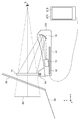
- FIG. 2 is a side view showing the configuration of the head-up display device 100.
- the head-up display device 100 includes a projection unit 12, a combiner 14, an optical member 16, a housing 50, a substrate unit 52, and a rotation shaft 54.
- the housing 50 of the head-up display device 100 is installed in or on the dashboard of the vehicle.
- substrate part 52 is arrange
- a display image (digital image data) is generated.
- the generated display image is input to the projection unit 12.
- the projection unit 12 houses optical elements such as a light source, an image display element, various optical lenses, and a mirror.
- the projection unit 12 generates and projects image display light based on the display image.
- LCOS Liquid Crystal On Silicon
- an image display device composed of a self-luminous element such as an LCD (Liquid Crystal Display) or an organic EL (Electro Luminescence) may be used as the image display element.
- the projection unit 12 may be laser beam scanning using a transmissive liquid crystal or a MEMS (Micro Electro Mechanical Systems) mirror.
- the optical member 16 is constituted by a concave mirror, for example.
- the optical member 16 changes the direction of the image display light toward the combiner 14 by reflecting the image display light projected from the projection unit 12.
- the combiner 14 is pivotally connected to the housing 50 by a pivot shaft 54 along the y-axis direction.
- the combiner 14 is disposed inside the windshield 56.
- the image display light reflected by the optical member 16 follows an optical path toward the combiner 14.
- the combiner 14 presents an image related to the image display light as a virtual image 60 to a user who is a passenger such as a driver.
- the combiner 14 allows the driver E to visually recognize the virtual image 60 by transmitting the external light incident through the windshield 56 and reflecting the image display light.
- the virtual image 60 is an enlarged image of the image display light emitted from the projection unit 12.
- the driver E recognizes as if the virtual image 60 is displayed above the hood 58, for example, 1.7 m to 2.0 m ahead (front of the vehicle) by looking at the combiner 14 with respect to the viewing direction.
- the combiner 14 is a half mirror. Therefore, the user who is the driver recognizes the video in which the virtual image 60 is superimposed on the scenery outside the vehicle desired through the windshield 56. Thereby, since the driver E who is a user can observe the virtual image 60 through the windshield 56, information can be obtained without moving the line of sight while driving the vehicle.
- the head-up display device 100 may project the virtual image 60 on the windshield 56 without including the combiner 14.
- a control unit (not shown) is mounted on the substrate unit 52 of the head-up display device 100.
- the control unit includes a communication IF (interface), and connects the electronic device 210 via the communication IF.
- the electronic device 210 includes an electronic device display unit 212 for displaying image data.
- the size of the image data that can be displayed on the electronic device display unit 212 is larger than the size of the virtual image 60.
- a communication method capable of transmitting image data from the electronic device 210 is applicable regardless of wired / wireless. Examples of such communication methods are HDMI (registered trademark), MHL (registered trademark), and Miracast (registered trademark). Acquisition of image data and generation of a display image in the control unit are executed, for example, every 0.1 second to 1 second.
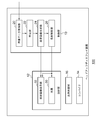
- FIG. 3 shows the configuration of the head-up display device 100.
- the head-up display device 100 includes a control unit 10, a projection unit 12, a combiner 14, and an optical member 16.
- the control unit 10 includes an image data acquisition unit 20, a specification unit 22, a display image generation unit 24, and a projection control unit 26, and the projection unit 12 includes a light source 30 and a projection image display unit 32.
- the control unit 10 is mounted on the substrate unit 52 of FIG.
- the image data acquisition unit 20 corresponds to the communication IF described above, is connected to an electronic device 210 (not shown), and acquires image data displayed on the electronic device display unit 212 of the electronic device 210. Since the connection with the electronic device 210 is the same as before, the description thereof is omitted here.
- the electronic device 210 is a device that can display information related to vehicle operation, and the information related to vehicle operation is, for example, map information, route information, and traffic jam information.
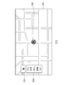
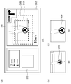
- FIG. 4 shows an example of an image displayed on the electronic device display unit 212 and corresponds to image data.
- This is image data when the electronic device 210 is a navigation device mounted on a vehicle.
- a map image is displayed in the map display range 302.
- the vehicle position icon 300 is displayed at the center of the map display range 302.
- the own vehicle position icon 300 is an icon for indicating the current position based on the GPS information of the navigation device, and the navigation device and the head-up display device 100 are used in the same vehicle. It is also the position where the vehicle to be installed exists.
- the map display range 302 includes a direction display unit 304 and a scale display unit 306.
- the specifying unit 22 specifies a display form included in the image data acquired by the image data acquiring unit 20 and which is a display target in the head-up display device 100.
- the display form has a predetermined shape, and an example of the predetermined shape is a shape corresponding to the vehicle position icon 300 of FIG.
- This vehicle position icon 300 can be said to be a display relating to the operation of the vehicle. Note that the shape of the vehicle position icon 300 varies depending on the type of the electronic device 210.
- the specifying unit 22 stores the shape of the own vehicle position icon 300 in the electronic device 210 that can be connected in the database, and the specifying unit 22 detects the shape of the own vehicle position icon 300 stored in the database from the image data. .
- the specifying unit 22 may update the contents of the database via a network. Further, the specifying unit 22 may search the history of the input image data, extract a display form that is continuously displayed, and store this in the database as the shape of the vehicle position icon 300.
- the display image generating unit 24 generates a display image by extracting a display range including the display form specified by the specifying unit 22 from the image data. Extracting the display range is equivalent to cutting out the display range.
- the display range is a predetermined range centered on the shape of the vehicle position icon 300 that is a display form, or a predetermined range centered below the shape of the vehicle position icon 300 that is a display form.
- the projection control unit 26 outputs the display image generated by the display image generation unit 24 to the projection image display unit 32.
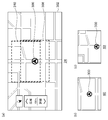
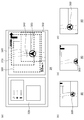
- FIGS. 5A to 5C show an outline of processing in the head-up display device 100.
- FIG. FIG. 5A is the same image data as in FIG. 4 and is image data acquired by the image data acquisition unit 20. Image data to be processed by the specifying unit 22 and the display image generation unit 24 is shown in FIG. Show.
- the own vehicle position icon 300 is specified by the specifying unit 22.
- the display image generation unit 24 extracts the first display range 308 so that the shape of the vehicle position icon 300 is the center.
- the display image generation unit 24 may extract the second display range 310 so that the shape of the own vehicle position icon 300 is positioned below the center.
- the display range is the first display range 308 or the second display range 310 may be set by the user via an operation unit (not shown). Further, the display range is not limited to the first display range 308 and the second display range 310.
- FIGS. 5B to 5C will be described later.
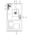
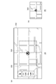
- FIGS. 6A to 6C show another processing outline in the head-up display device 100.
- FIG. FIG. 6A shows image data when the electronic device 210 is a smartphone.
- a map image is displayed in the map display range 302
- a traveling direction arrow display unit 312 and a traveling direction distance display unit 314 are displayed above the map display range 302.
- the vehicle position icon 300 is displayed in the map display range 302.
- the vehicle position icon 300 is specified by the specifying unit 22.
- the display image generation unit 24 extracts the first display range 308 so that the shape of the own vehicle position icon 300 is centered, and the second display range so that the shape of the own vehicle position icon 300 is lower than the center. 310 is extracted.
- FIGS. 6B to 6C will be described later, and the description returns to FIG.
- the projection image display unit 32 is an image display element in the description of the projection unit 12 described above, and the display image from the display image generation unit 24 is input to display an image to be displayed.
- the projection image display unit 32 is irradiated with light emitted from the light source 30, and the reflected light is projected onto the optical member 16.
- the projection control unit 26 controls the luminance and display timing of the image displayed by the projection image display unit 32, the luminance and operation timing of the light source 30, and the like.
- the projection control unit 26 controls the display image luminance of the projection image display unit 32 and the luminance of the light source 30 based on information such as an image signal from the display image generation unit 24 and an illuminance sensor (not shown).
- the projection control unit 26 controls the irradiation of the light source 30 and the display of the projection image display unit 32 based on the display image. Since control of display and the like is a known technique, description thereof is omitted here.
- FIGS. 5B to 5C show a virtual image 60 which is a display image.
- FIG. 5B shows a virtual image 60 when the first display range 308 in FIG. 5A is the display range
- FIG. 5C shows the second display range 310 in FIG.
- a virtual image 60 in the case of the display range is shown.
- FIGS. 6B to 6C show a virtual image 60 which is a display image.
- FIG. 6B shows the virtual image 60 when the first display range 308 in FIG. 6A is the display range
- FIG. 6C shows the second display range 310 in FIG.
- a virtual image 60 in the case of the display range is shown.
- This configuration can be realized in terms of hardware by a CPU, memory, or other LSI of any computer, and in terms of software, it can be realized by a program loaded in the memory, but here it is realized by their cooperation.
- Draw functional blocks Accordingly, those skilled in the art will understand that these functional blocks can be realized in various forms by hardware only, software only, or a combination thereof.
- a display image is generated by specifying a display form to be displayed from image data displayed on an electronic device and extracting a display range including the specified display form from the image data.
- the processing independent of the type of electronic device can be executed.
- a head-up display device that can be connected to various types of electronic devices can be provided.
- a display image is generated by extracting a part of the image data as a display range, even if the display size of the head-up display device is smaller than the display size of the electronic device, the display by the head-up display device Image display can be realized.
- the process can be simplified if the display form is stored in advance. Further, since the shape corresponding to the vehicle position icon is specified, the display form that is always displayed in the image data can be specified. In addition, since the display form that is always displayed in the image data is specified, a display image can be reliably generated from the image data.
- a second embodiment of the present invention relates to a head-up display device mounted on a vehicle, similarly to the first embodiment.
- a map display range is provided, but in the image data in the second embodiment, in addition to the map display range, a range in which information not related to vehicle operation is displayed is also provided.
- the head-up display device according to the second embodiment generates and displays a display image from the image data even when such image data is acquired.
- the head-up display device 100 according to the second embodiment is the same type as that shown in FIGS. Here, it demonstrates centering on the difference from before.
- FIG. 7 shows the configuration of the head-up display device 100.
- the head-up display device 100 includes a control unit 10, a projection unit 12, a combiner 14, and an optical member 16.
- the control unit 10 includes an image data acquisition unit 20, a partial image data extraction unit 28, a specification unit 22, a display image generation unit 24, and a projection control unit 26, and the projection unit 12 includes a light source 30 and a projection image display unit 32. .
- the image data acquisition unit 20 acquires the image data displayed on the electronic device display unit 212 of the electronic device 210 as before.
- FIG. 8 shows an example of an image displayed on the electronic device display unit 212 and corresponds to image data. This also shows a case where the electronic device 210 is a navigation device mounted on a vehicle.
- a map display range 302 is provided on the right side of the electronic device display unit 212, and a content information display range 320 is provided on the left side of the electronic device display unit 212.
- the vehicle position icon 300 is displayed in the map display range 302 as before.
- the map display range 302 is provided with a traveling direction display range 316 and a speed display range 318.
- the traveling direction display range 316 displays a traveling direction arrow display unit 312 and a traveling direction distance display unit 314. .
- a reproduction content information display range 322 and a reproduction content image display range 324 are displayed.
- the content information display range 320 is an area in which information on the content data being reproduced is displayed, and is an area in which information not related to vehicle operation is displayed.
- the partial image data extraction unit 28 extracts the map display range 302 as partial image data from the image data acquired by the image data acquisition unit 20.
- a map display range 302 that is partial image data information related to vehicle operation is displayed.
- the specifying unit 22 specifies a display form included in the partial image data extracted by the partial image data extracting unit 28 and which is a display target in the head-up display device 100.
- the display form is the same as heretofore, for example, a shape corresponding to the vehicle position icon 300 of FIG.
- the display image generating unit 24 generates a display image by extracting a display range including the display form specified by the specifying unit 22 from the image data.
- 9A to 9C show an outline of processing in the head-up display device 100.
- FIG. FIG. 9A is the same image data as in FIG. 8 and the image data acquired by the image data acquisition unit 20, and the processing in the partial image data extraction unit 28, the specification unit 22, and the display image generation unit 24.
- the map display range 302 is extracted as partial image data by the partial image data extraction unit 28.
- the own vehicle position icon 300 is specified by the specifying unit 22.
- the display image generation unit 24 extracts the first display range 308 centered on the shape of the own vehicle position icon 300 in the map display range 302 that is partial image data, or sets the shape of the own vehicle position icon 300 to the lower center.
- the second display range 310 may be extracted. Again, the display range is not limited to the first display range 308 and the second display range 310.
- FIG. 9B shows a virtual image 60 when the first display range 308 in FIG. 9A is the display range
- FIG. 9C shows the second display range 310 in FIG. 9A. A virtual image 60 in the case of the display range is shown.
- the partial image data is extracted from the image data, and the display form is specified from the partial image data. Therefore, even when the image data displays information other than information related to vehicle operation, the image is displayed. A display image can be generated from the data. In addition, even when the image data displays information other than information related to the operation of the vehicle, the display image is generated from the image data, so that various types of image data can be handled.
- Example 3 of the present invention relates to a head-up display device mounted on a vehicle as before, and displays a display area that includes a display form from image data or partial image data. Generate an image.
- a display form such as arrows and numbers are specified, and a display image is generated by combining them.
- the head-up display device 100 according to the third embodiment is the same type as that shown in FIGS. 1, 2, 3, and 7. Here, it demonstrates centering on the difference from before.
- the 3 or 7 specifies a display form included in the image data acquired by the image data acquisition unit 20 or the partial image data extracted by the partial image data extraction unit 28.
- the display form has a predetermined shape, and identifies the shape corresponding to the vehicle position icon 300 as described above.
- the specifying unit 22 may specify an arrow shape as the predetermined shape.
- the arrow shape is a display for indicating a traveling direction such as a right turn, a left turn, or a straight line at an intersection or the like when the electronic device 210 is performing route guidance.
- the specifying unit 22 may specify a shape corresponding to a number as the predetermined shape.
- the shape related to the numbers is a display for indicating the distance to the intersection to be turned right or left when the electronic device 210 is performing route guidance.
- the shape related to the numbers may be a display for indicating the traveling speed of the vehicle on which the head-up display device 100 is mounted.
- the predetermined shape specified by the specifying unit 22 may be limited to a shape having a predetermined display size or more. This is to avoid specifying the name of the building included in the map image.
- FIG. 10 shows an outline of processing in the head-up display device 100 according to the third embodiment of the present invention. This is shown in the same manner as in FIG. 8, and a map display range 302 that is partial image data is input to the specifying unit 22.
- the specifying unit 22 specifies a shape corresponding to the vehicle position icon 300. Further, the specifying unit 22 specifies the arrow display shape 332 as the arrow shape. Furthermore, the specifying unit 22 specifies a distance display shape 334 and a speed display shape 336 as shapes corresponding to numbers.
- the display image generation unit 24 extracts each shape specified by the specifying unit.
- the display image generation unit 24 generates a display image based on each extracted shape.
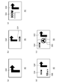
- 11A to 11E show an outline of processing in the head-up display device 100. FIG. These are display images generated by the display image generation unit 24 and a virtual image 60 to be displayed.
- FIG. 11A shows a display image generated only with the arrow display shape 332.
- FIGS. 11B to 11C show display images generated by combining the arrow display shape 332 and the distance display shape 334.
- FIG. 11D shows a display image generated by combining the arrow display shape 332, the distance display shape 334, and the speed display shape 336.
- FIG. 11E shows a display image generated by combining the vehicle position icon display shape 330, the arrow display shape 332, and the distance display shape 334.
- the display image generation unit 24 may execute the following processing when generating a display image by combining a plurality of shapes.
- the display image generation unit 24 generates a display image so as to maintain the relative positional relationship between the shapes in the map display range 302. For example, the display image generation unit 24 arranges the arrow display shape 332 in the upper right portion, arranges the distance display shape 334 on the left side of the arrow display shape 332, and maintains the speed in the lower left portion so as to maintain the positional relationship in FIG.
- a display shape 336 is arranged.
- the display image generation unit 24 generates a display image so as to reflect the direction of the arrow in the arrow display shape 332. For example, when the arrow points to the right, the arrow display shape 332 is arranged on the right portion, and when the arrow points to the left, the arrow display shape 332 is arranged on the left portion.
- the display image generation unit 24 generates a display image so as to preferentially indicate a shape that is not normally displayed but temporarily displayed. For example, the arrow display shape 332 is not displayed except in the vicinity of the intersection, and is displayed in the vicinity of the intersection. Therefore, the display image generation unit 24 preferentially arranges the arrow display shape 332.
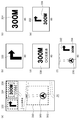
- FIGS. 12A to 12F show another processing outline in the head-up display device 100.
- FIG. FIG. 12A is shown in the same manner as FIG. 6A, and the specifying unit 22 specifies the shape corresponding to the vehicle position icon 300 from the image data acquired from the smartphone by the image data acquiring unit 20. . Further, the specifying unit 22 specifies the arrow display shape 332 as the arrow shape. Further, the specifying unit 22 specifies the distance display shape 334 and the information display shape 338 as shapes corresponding to numbers.
- FIGS. 12B to 12F are display images generated by the display image generation unit 24 and a virtual image 60 to be displayed.
- FIG. 12B shows a display image generated using only the arrow display shape 332.
- FIG. 11C shows a display image generated with only the distance display shape 334.
- FIG. 11D shows a display image generated with only the information display shape 338.
- FIG. 11E shows a display image generated by combining the arrow display shape 332 and the distance display shape 334.
- FIG. 12F shows a display image generated by combining the vehicle position icon display shape 330, the arrow display shape 332, and the distance display shape 334.
- the traveling direction such as a right turn or a left turn
- information to be noted as the traveling direction can be specified from the image data.
- information to be noted as the traveling direction can be included in the display image.
- information such as distance and speed can be specified from the image data.
- information such as distance and speed can be included in the display image.
- the display form more than the predetermined display size is specified, it is possible to prevent the information displayed small from being specified. In addition, since the information displayed in a small size is prevented, the visibility of the display image can be improved.
- Example 4 of the present invention relates to a head-up display device mounted on a vehicle as before, and by displaying a display area that includes a display form from image data or partial image data, Generate an image. Even in the fourth embodiment, a display area that includes a display form is extracted from image data or partial image data, but the position to be extracted is limited. That is, in the fourth embodiment, a display image is generated by extracting an arbitrary position without being limited to the central portion of the image data.
- the head-up display device 100 according to the fourth embodiment is the same type as that shown in FIGS. 1, 2, 3, and 7. Here, it demonstrates centering on the difference from before.
- the display form has a predetermined shape, for example, a shape corresponding to the vehicle position icon 300 is specified.
- the host vehicle position icon 300 is a display form of a predetermined position to be displayed, and is not limited to the central portion of the image data, and may be an arbitrary position.
- the display image generating unit 24 extracts a display range including a shape corresponding to the specified vehicle position icon 300 from the display form specified by the specifying unit 22.
- the display range may not be the center of the image data.
- the position and range of the display range can be arbitrarily designated via an operation unit (not shown). Note that if the user does not arbitrarily specify, the operation unit is not necessary.
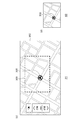
- FIGS. 13A to 13D show an outline of processing in the head-up display device 100.
- FIG. FIG. 13A is shown similarly to FIG. 4, and the specifying unit 22 specifies a shape corresponding to the vehicle position icon 300 from the map display range 302 that is image data.
- the display image generation unit 24 specifies one of the first display range 308, the second display range 310, and the third display range 340.
- the first display range 308, the second display range 310, and the third display range 340 include the vehicle position icon 300.
- FIG. 13B shows a virtual image 60 when the first display range 308 in FIG. 13A is the display range
- FIG. 13C shows the second display range 310 in FIG.
- the virtual image 60 when the display range is set is shown
- FIG. 13D shows the virtual image 60 when the third display range 340 in FIG. 13A is set as the display range.
- FIGS. 14A to 14C show another processing outline in the head-up display device 100.
- FIG. FIG. 14A is shown in the same manner as FIG. 6A, and the specifying unit 22 specifies the shape corresponding to the vehicle position icon 300 from the image data acquired from the smartphone by the image data acquiring unit 20. .
- the display image generation unit 24 specifies either the first display range 308 or the second display range 310.
- FIG. 14B shows the virtual image 60 when the first display range 308 in FIG. 14A is the display range
- FIG. 14C shows the second display range 310 in FIG.
- a virtual image 60 in the case of the display range is shown.
- FIGS. 15A to 15D show still another processing outline in the head-up display device 100.
- FIG. FIG. 15A is similar to FIG. 8, and the specifying unit 22 specifies a shape corresponding to the vehicle position icon 300 from the map display range 302 that is partial image data.
- the display image generation unit 24 specifies one of the first display range 308, the second display range 310, and the third display range 340.
- FIG. 15B shows the virtual image 60 when the first display range 308 in FIG. 15A is the display range
- FIG. 15C shows the second display range 310 in FIG.
- the virtual image 60 when the display range is set is shown
- FIG. 15D shows the virtual image 60 when the third display range 340 in FIG. 15A is set as the display range.
- the display form at a predetermined position is specified from the image data
- the display form arranged at an arbitrary position can be specified. Further, since the display form arranged at an arbitrary position is specified, the degree of freedom of layout of the display image can be improved.
- Embodiment 5 of the present invention relates to a head-up display device mounted on a vehicle as before, and displays a display area that includes a display form from image data or partial image data. Generate an image. Even in the fifth embodiment, a display area including a display form is extracted from image data or partial image data, but the position to be extracted is limited. That is, in the fifth embodiment, the display image is generated by extracting the display range including the central portion of the image data.
- the head-up display device 100 according to the fifth embodiment is the same type as that shown in FIGS. 1, 2, 3, and 7. Here, it demonstrates centering on the difference from before.
- 3 or 7 is a display form included in the image data acquired by the image data acquisition unit 20 or the partial image data extracted by the partial image data extraction unit 28, and is arranged at a predetermined position.
- the displayed display form is specified.
- the predetermined position is the central portion of the image data or partial image data.
- the display image generation unit 24 generates a display image by extracting a display range including the center portion in the image data from the information on the center portion specified by the specifying unit 22. This is because information necessary for route guidance such as the vehicle position information is displayed near the center of the image data in the navigation device or the navigation application.
- the position and range of the display range can be arbitrarily designated via an operation unit (not shown). Note that if the user does not arbitrarily specify, the operation unit is not necessary.
- FIGS. 16A to 16D are diagrams showing an outline of processing in the head-up display device 100.
- FIG. FIG. 16A is shown in the same manner as FIG. 4, and the specifying unit 22 specifies the map center 342 that is the central portion of the image data from the map display range 302 that is the image data.
- the display image generation unit 24 specifies one of the first display range 308, the second display range 310, and the third display range 340.
- the first display range 308, the second display range 310, and the third display range 340 include a map center 342.
- the vehicle position icon 300 is arranged at the map center 342, but the vehicle position icon 300 may not be arranged at the map center 342.
- FIG. 16A the vehicle position icon 300 is arranged at the map center 342, but the vehicle position icon 300 may not be arranged at the map center 342.
- FIG. 16B shows a virtual image 60 when the first display range 308 in FIG. 16A is the display range
- FIG. 16C shows the second display range 310 in FIG. A virtual image 60 when the display range is set is shown
- FIG. 16D shows the virtual image 60 when the third display range 340 in FIG. 16A is set as the display range.
- FIGS. 17A to 17C show another processing outline in the head-up display device 100.
- FIG. FIG. 17A is shown in the same manner as FIG. 6A, and the specifying unit 22 specifies the map center 342 that is the central part of the image data from the image data acquired by the image data acquiring unit 20 from the smartphone. To do.
- the display image generation unit 24 specifies either the first display range 308 or the second display range 310.
- FIG. 17B shows the virtual image 60 when the first display range 308 in FIG. 17A is the display range
- FIG. 17C shows the second display range 310 in FIG.
- a virtual image 60 in the case of the display range is shown.
- FIG. 18A to 18D show still another processing outline in the head-up display device 100.
- FIG. FIG. 18A is shown in the same manner as FIG. 8, and the specifying unit 22 specifies the map center 342 that is the central part of the partial image data.
- the display image generation unit 24 specifies one of the first display range 308, the second display range 310, and the third display range 340.
- FIG. 18B shows a virtual image 60 when the first display range 308 in FIG. 18A is the display range
- FIG. 18C shows the second display range 310 in FIG.
- the virtual image 60 when the display range is set is shown
- FIG. 18D shows the virtual image 60 when the third display range 340 in FIG. 18A is set as the display range.
- the central portion of the image data is specified, it is possible to specify a portion close to the position where the vehicle exists. Moreover, since the part close
- Example 6 of the present invention relates to a head-up display device mounted on a vehicle, as before, and displays a display area that includes a display form from image data or partial image data. Generate an image.
- a display image is generated by extracting a display range that is biased in the traveling direction.
- the head-up display device 100 according to the sixth embodiment is the same type as that shown in FIGS. Here, it demonstrates centering on the difference from before.
- FIG. 19 shows a configuration of the head-up display device 100 according to the sixth embodiment of the present invention.
- the head-up display device 100 includes a control unit 10, a projection unit 12, a combiner 14, and an optical member 16.
- the control unit 10 includes an image data acquisition unit 20, a specification unit 22, a display image generation unit 24, a projection control unit 26, and an information acquisition unit 40, and the projection unit 12 includes a light source 30 and a projection image display unit 32.
- the image data acquisition unit 20 and the identification unit 22 execute the same processing as before.
- a partial image data extraction unit 28 may be disposed between the image data acquisition unit 20 and the specifying unit 22.
- the information acquisition unit 40 acquires information on the traveling direction of the vehicle on which the head-up display device 100 is mounted.
- the information acquisition unit 40 outputs information on the traveling direction of the vehicle to the display image generation unit 24.
- a positioning unit (not shown) receives position signals of the vehicle by receiving signals from GPS satellites.
- the positioning unit acquires a history of position information by repeatedly performing positioning. Further, the positioning unit acquires information on the traveling direction of the vehicle based on the history of the position information.
- the positioning unit outputs information on the traveling direction of the vehicle to the information acquisition unit 40.
- the information acquisition unit 40 acquires information on the traveling direction of the vehicle from the navigation device and the navigation application.
- the information acquisition unit 40 detects a transition associated with travel of a characteristic shape of the image data acquired by the image data acquisition unit 20. For example, when the detected transition is a transition in a specific direction (downward on the screen), the information acquisition unit 40 acquires that the vehicle is moving upward as information on the traveling direction of the vehicle.
- the display image generation unit 24 generates a display image by extracting the display range including the display form specified by the specification unit 22 while reflecting the image data in the traveling direction of the vehicle. More specifically, the display image generating unit 24 sets the display range so that the portion on the vehicle traveling direction side is wider than the portion on the opposite side of the vehicle traveling direction, thereby moving the vehicle in the vehicle traveling direction. Set an uneven display range. For example, when the upper side of the image data is set in the traveling direction of the vehicle, the display image generation unit 24 sets the display range so that the vehicle position icon 300 is on the lower side.
- the top of the display range may be fixed to the top of the image data, or the top of the display range may be set to be within a predetermined range, for example, 10% from the top of the image data. Good.
- FIG. 20A to 20D show an outline of processing in the head-up display device 100.
- FIG. FIG. 20A is shown in the same manner as FIG. 4, and the specifying unit 22 specifies the shape corresponding to the vehicle position icon 300 from the map display range 302 that is image data.
- specifying the shape corresponding to the vehicle position icon 300 corresponds to specifying the central portion.
- the display image generation unit 24 specifies one of the first display range 308, the second display range 310, and the third display range 340. In each of the first display range 308, the second display range 310, and the third display range 340, the part on the vehicle traveling direction side is wider than the part on the opposite side of the vehicle traveling direction.
- FIG. 20B shows the virtual image 60 when the first display range 308 in FIG.
- FIG. 20A is the display range
- FIG. 20C shows the second display range 310 in FIG. A virtual image 60 when the display range is set is shown
- FIG. 20D shows the virtual image 60 when the third display range 340 in FIG. 20A is set as the display range.
- FIGS. 21A to 21C show another processing outline in the head-up display device 100.
- FIG. FIG. 21A is shown in the same manner as FIG. 6A, and the specifying unit 22 specifies the shape corresponding to the host vehicle position icon 300, that is, the center portion.
- the display image generation unit 24 specifies either the first display range 308 or the second display range 310 from the image data acquired by the image data acquisition unit 20 from the smartphone.
- the vehicle position icon 300 may not be included in the first display range 308 and the second display range 310.
- FIG. 21B shows a virtual image 60 when the first display range 308 in FIG. 21A is the display range
- FIG. 21C shows the second display range 310 in FIG.
- a virtual image 60 in the case of the display range is shown.
- FIGS. 22A to 22D show still another processing outline in the head-up display device 100.
- FIG. FIG. 21A is shown in the same manner as FIG. 8, and the specifying unit 22 specifies the shape corresponding to the vehicle position icon 300, that is, the center portion, from the map display range 302 that is the partial image data.
- the display image generation unit 24 specifies one of the first display range 308, the second display range 310, and the third display range 340.
- FIG. 21B shows a virtual image 60 when the first display range 308 in FIG. 21A is the display range
- FIG. 21C shows the second display range 310 in FIG.
- the virtual image 60 when the display range is set is shown
- FIG. 21D shows the virtual image 60 when the third display range 340 in FIG. 21A is set as the display range.
- the display image is generated by extracting the display range reflecting the information on the traveling direction from the image data, it is possible to generate a display image having a wider traveling direction side.
- the display area of the map image in the direction of traveling can be increased.
- the display area of the map image in the direction in which it will proceed is enlarged, a lot of useful information can be displayed.
- Example 7 of the present invention relates to a head-up display device mounted on a vehicle, as before, and displays a display area that includes a display form from image data or partial image data. Generate an image.
- a display image is generated by extracting a display range deviated in the traveling direction.
- a display image is generated by extracting a display range deviated in the turning direction.
- the head-up display device 100 according to the seventh embodiment is the same type as that shown in FIGS. Here, it demonstrates centering on the difference from before.
- the information acquisition unit 40 in FIG. 19 acquires information on the turning direction of the vehicle on which the head-up display device 100 is mounted.
- the information acquisition unit 40 outputs information on the turning direction of the vehicle to the display image generation unit 24.
- at least one of four types of processing described below is executed.
- a positioning unit receives the signal from the GPS satellite to measure the position information of the vehicle.
- the positioning unit acquires a history of position information by repeatedly performing positioning. Further, the positioning unit acquires information on the turning direction of the vehicle based on the history of position information. Note that the positioning unit may use information from the acceleration sensor to acquire information on the turning direction of the vehicle.
- the positioning unit outputs information on the turning direction of the vehicle to the information acquisition unit 40.
- the information acquisition unit 40 acquires information on the turning direction of the vehicle from the navigation device and the navigation application. Information on the turning direction of the vehicle is derived along the route.
- the information acquisition unit 40 detects a transition associated with travel of a characteristic shape of the image data acquired by the image data acquisition unit 20. For example, when the detected transition is rotational movement, the information acquisition unit 40 acquires that the vehicle is turning in the direction opposite to the rotation direction as information on the turning direction of the vehicle. On the other hand, when the detected transition is a transition in a specific direction (downward on the screen), the information acquisition unit 40 does not acquire that the vehicle is turning because it is traveling straight ahead.
- the information acquisition unit 40 is connected to a steering angle sensor for detecting the steering angle of the steering wheel 206 of the vehicle via a CAN (Controller Area Network).
- the information acquisition unit 40 is connected to the steering angle sensor. Get information about.
- the information acquisition unit 40 acquires the detected turning in the steering direction as information on the turning direction of the vehicle when the acquired information indicates a steering angle greater than or equal to a predetermined angle.
- the display image generation unit 24 generates a display image by extracting the display range including the display form specified by the specification unit 22 from the image data by reflecting information on the turning direction of the vehicle. More specifically, the display image generation unit 24 sets the display range so that a portion on the side of the vehicle turning direction is wider than a portion on the opposite side of the vehicle turning direction. Set an uneven display range.
- FIGS. 23A to 23B show an outline of processing in the head-up display device 100.
- FIG. FIG. 23A is shown in the same manner as FIG. 4, and the specifying unit 22 specifies the shape corresponding to the vehicle position icon 300 from the map display range 302 that is image data.
- specifying the shape corresponding to the vehicle position icon 300 corresponds to specifying the central portion.
- the display image generation unit 24 specifies the first display range 308.
- FIG. 23B shows a virtual image 60 when the first display range 308 is specified in FIG.
- FIGS. 24 (a)-(b) show the outline of the process in the head-up display device 100 following the outline of the process in FIGS. 23 (a)-(b).
- FIG. 24A shows the same as FIG. 23A, but shows a case where the vehicle is turning rightward from the state shown in FIG.
- the first display range 308 is set with respect to the host vehicle position icon 300 so that the portion on the vehicle turning direction side is wider than the portion on the opposite side of the vehicle turning direction.
- FIG. 24B shows a virtual image 60 when the first display range 308 is specified in FIG.
- FIG. 25 (a)-(b) shows an outline of processing in the head-up display device 100 following the outline of processing in FIGS. 24 (a)-(b).
- FIG. 25 (a) is shown in the same manner as FIG. 24 (a), but shows a case where the vehicle is further turning rightward from the state shown in FIG. 24 (a).
- the first display range 308 is set for the vehicle position icon 300 so that the portion on the vehicle turning direction side is wider than the portion on the opposite side of the vehicle turning direction.
- the FIG. 25B shows a virtual image 60 when the first display range 308 is specified in FIG.
- FIG. 26 (a)-(b) shows an outline of processing in the head-up display device 100 following the outline of processing in FIGS. 25 (a)-(b).
- FIG. 26A shows the same as FIG. 25A, but shows the case where the turning of the vehicle has ended from the state shown in FIG. Therefore, the first display range 308 is set so that the vehicle position icon 300 is the central portion.
- FIG. 26B shows a virtual image 60 when the first display range 308 is specified in FIG.
- a display image is generated by extracting a display range reflecting the information on the turning direction from the image data, so that a display image with a wider turning direction can be generated.
- the display area of the map image in the direction of turning can be increased.
- the display area of the map image in the direction of turning is enlarged, a lot of useful information can be displayed.
- the display image generation unit 24 generates a display image.
- the present invention is not limited to this.
- the display image generation unit 24 may perform a color reduction process when generating a display image.
- An example of the color reduction process is to use one color or two colors when the display range extracted from the image data is composed of three or more colors.
- the display image generation unit 24 may make the background color colorless.
- control unit 10 control unit, 12 projection unit, 14 combiner, 16 optical member, 20 image data acquisition unit, 22 identification unit, 24 display image generation unit, 26 projection control unit, 30 light source, 32 projection image display unit, 50 housing, 52 substrate part, 54 rotation axis, 56 windshield, 58 bonnet, 60 virtual image, 100 head-up display device.
- a head-up display device that can be connected to various types of electronic devices can be provided.
Landscapes
- Engineering & Computer Science (AREA)
- Radar, Positioning & Navigation (AREA)
- Physics & Mathematics (AREA)
- Remote Sensing (AREA)
- Mechanical Engineering (AREA)
- Transportation (AREA)
- Chemical & Material Sciences (AREA)
- Combustion & Propulsion (AREA)
- General Physics & Mathematics (AREA)
- Automation & Control Theory (AREA)
- Optics & Photonics (AREA)
- Instrument Panels (AREA)
- Navigation (AREA)
- Controls And Circuits For Display Device (AREA)
Abstract
画像データ取得部20は、車両の運行に関する情報を表示可能な電子機器に接続され、電子機器に表示される画像データを取得する。特定部22は、画像データ取得部20において取得した画像データから、表示対象となる表示形態を特定する。表示画像生成部24は、特定部22において特定した表示形態を含む表示範囲を画像データから抽出することによって、表示画像を生成する。投射部12は、表示画像生成部24において生成した表示画像をユーザが虚像として視認できるように投射する。
Description
本発明は、投射技術に関し、特に画像表示光に基づく画像を虚像としてユーザに提示するヘッドアップディスプレイ装置および投射方法に関する。
車両に搭載されるヘッドアップディスプレイ装置の普及が拡大している。ヘッドアップディスプレイ装置は、一般的にナビゲーション装置と併用される場合が多く、例えば、ヘッドアップディスプレイ装置は、ナビゲーション装置に接続され、ナビゲーション装置から表示データを取得する。ヘッドアップディスプレイ装置において表示可能な情報量は、通常、ナビゲーション装置の表示画面に表示される情報量よりも少ない。そのため、ナビゲーション装置からヘッドアップディスプレイ装置に対して出力される情報は、特定の情報に限定される(例えば、特許文献1参照)。
ナビゲーション装置は多様化しており、車両に搭載されるナビゲーション装置や、ポータブルナビゲーション装置、スマートフォンやタブレット端末によるナビゲーションアプリケーションなどがある。また、ナビゲーションアプリケーションもさまざまであり、特定のナビゲーションアプリケーションにおいてもそのバージョンによって機能や表示形態が変更される。
本発明はこうした状況に鑑みてなされたものであり、その目的は、さまざまなタイプの電子機器に接続可能なヘッドアップディスプレイ装置を提供することである。
上記課題を解決するために、本発明のある態様のヘッドアップディスプレイ装置は、車両の運行に関する情報を表示可能な電子機器に接続され、電子機器に表示される画像データを取得する画像データ取得部と、画像データ取得部において取得した画像データから、表示対象となる表示形態を特定する特定部と、特定部において特定した表示形態を含む表示範囲を画像データから抽出することによって、表示画像を生成する表示画像生成部と、表示画像生成部において生成した表示画像をユーザが虚像として視認できるように投射する投射部と、を備える。
本発明の別の態様は、投射方法である。この方法は、車両の運行に関する情報を表示可能な電子機器に表示される画像データを取得するステップと、取得した画像データから、表示対象となる表示形態を特定するステップと、特定した表示形態を含む所定の表示範囲を画像データから抽出することによって、表示画像を生成するステップと、生成した表示画像をユーザが虚像として視認できるように投射するステップと、を備える。
なお、以上の構成要素の任意の組合せ、本発明の表現を方法、装置、システム、記録媒体、コンピュータプログラムなどの間で変換したものもまた、本発明の態様として有効である。
本発明によれば、さまざまなタイプの電子機器に接続可能なヘッドアップディスプレイ装置を提供できる。
(実施例1)
本発明を具体的に説明する前に、まず前提を説明する。本発明の実施例1は、車両に搭載されるヘッドアップディスプレイ装置に関する。ヘッドアップディスプレイ装置は、電子機器に接続されており、当該電子機器から画像データを取得すると、画像データをもとに表示画像を生成して、生成した表示画像を投射する。前述のごとく、このようなヘッドアップディスプレイ装置には、さまざまな種類の電子機器に接続可能な汎用性の高さが求められる。これに対応するために、本実施例に係るヘッドアップディスプレイ装置は、電子機器から取得した画像データのうち、自車位置アイコンを含む表示範囲を切り出して表示画像を生成する。表示画像における表示範囲は、ヘッドアップディスプレイ装置において表示可能なサイズに設定されており、その位置はヘッドアップディスプレイ装置から変更可能である。
本発明を具体的に説明する前に、まず前提を説明する。本発明の実施例1は、車両に搭載されるヘッドアップディスプレイ装置に関する。ヘッドアップディスプレイ装置は、電子機器に接続されており、当該電子機器から画像データを取得すると、画像データをもとに表示画像を生成して、生成した表示画像を投射する。前述のごとく、このようなヘッドアップディスプレイ装置には、さまざまな種類の電子機器に接続可能な汎用性の高さが求められる。これに対応するために、本実施例に係るヘッドアップディスプレイ装置は、電子機器から取得した画像データのうち、自車位置アイコンを含む表示範囲を切り出して表示画像を生成する。表示画像における表示範囲は、ヘッドアップディスプレイ装置において表示可能なサイズに設定されており、その位置はヘッドアップディスプレイ装置から変更可能である。
以下、本発明の実施例について、図面を参照しつつ説明する。かかる実施例に示す具体的な数値等は、発明の理解を容易とするための例示にすぎず、特に断る場合を除き、本発明を限定するものではない。なお、本明細書および図面において、実質的に同一の機能、構成を有する要素については、同一の符号を付することにより重複説明を省略し、本発明に直接関係のない要素は図示を省略する。以下で説明する実施例に係る画像投射装置は車載用のものを前提とするが、実施例に係る画像投射装置は車載用に限られず、航空機やゲーム機、娯楽施設等においても利用することができる。
図1は、本発明の実施例1に係るヘッドアップディスプレイ装置100が搭載される車室内を後方から見た別の外観図である。図1に示すように、x軸、y軸、z軸からなる直角座標系が規定される。x軸は、車両の長さ方向に延び、y軸は、車両の幅方向に延び、z軸は、車両の高さ方向に延びる。また、x軸、y軸、z軸のそれぞれの正の方向は、図1における矢印の方向に規定され、負の方向は、矢印と逆向きの方向に規定される。ここで、x軸の正方向が図1のステアリングホイール206から運転席に向かう方向であり、「正面側」、「後方」ということもあり、x軸の負方向が図1のステアリングホイール206からウインドシールド56に向かう方向であり、「背面側」、「前方」ということもある。また、z軸の正方向を「上面側」といい、z軸の負方向を「下面側」ということもある。
本実施例の説明は車両の右側にステアリングホイール206が配置される車両の例として説明するため、車室内の前方において、y軸の正方向側にステアリングホイール206が配置される。そのため、図示しない運転席もy軸の正方向側に配置され、助手席はy軸の負方向側に配置される。なお、ステアリングホイール206および運転席がy軸の負方向側に配置されてもよい。
ダッシュボード204のx軸の負方向側には、ウインドシールド56が配置され、ウインドシールド56のz軸の正方向側には、リアビューミラー200が配置される。さらに、ステアリングホイール206のy軸の負方向側、例えばセンタコンソール208には、電子機器210が設置される。電子機器210は、例えば、車両に搭載されるナビゲーション装置であり、カーナビゲーションシステムの画像等を表示する。
なお、電子機器210は、ナビゲーションアプリケーションが動作するスマートフォンやタブレット端末、映像出力のあるポータブルナビゲーション装置であってもよい。また、ステアリングホイール206のx軸の負方向側にはインスツルメントパネル202、ヘッドアップディスプレイ装置100が配置され、ヘッドアップディスプレイ装置100は、ウインドシールド56またはコンバイナに虚像60を表示する。
図2は、ヘッドアップディスプレイ装置100の構成を示す側面図である。ヘッドアップディスプレイ装置100は、投射部12、コンバイナ14、光学的部材16、筐体50、基板部52、回動軸54を含む。
ヘッドアップディスプレイ装置100の筐体50は、車両のダッシュボード内またはダッシュボード上に設置される。基板部52は、筐体50内に配置されており、投射部12およびその他の図示しない構成要素を搭載する。その他の図示しない構成要素については後述するが、例えば、表示画像(デジタル画像データ)が生成される。生成された表示画像は、投射部12に入力される。
投射部12には、光源、画像表示素子、各種光学レンズおよび鏡などの光学素子が収納される。投射部12は、表示画像をもとに画像表示光を生成して投射する。画像表示素子には、例えば、反射型液晶表示パネルであるLCOS(Liquid Crystal On Silicon)が使用される。また、画像表示素子に、LCD(Liquid Crystal Display)、有機EL(Electro Luminescence)等の自発光する素子からなる画像表示デバイスが使用されてもよい。また、投射部12は、透過型液晶、MEMS(Micro Electro Mechanical Systems)ミラーによるレーザ光走査であってもよい。
光学的部材16は、例えば、凹面鏡によって構成される。光学的部材16は、投射部12から投射された画像表示光を反射することによって、画像表示光の方向をコンバイナ14の方に変える。
コンバイナ14は、y軸方向に沿った回動軸54によって、筐体50に回動可能に接続される。また、コンバイナ14は、ウインドシールド56の車内側に配置される。光学的部材16において反射された画像表示光は、コンバイナ14に向かう光路を辿る。コンバイナ14は、画像表示光に係る画像を虚像60として運転者等の搭乗者であるユーザに提示する。コンバイナ14は、ウインドシールド56を介して入射する外来光を透過するとともに、画像表示光を反射することによって虚像60を運転者Eに視認させる。虚像60は、投射部12から放射される画像表示光の画像が拡大された像である。運転者Eは視線方向に対してコンバイナ14を見ることで、例えば1.7m~2.0m前方(車両前方)のボンネット58の上方に虚像60が表示されているかのように認識する。
コンバイナ14は、ハーフミラーである。そのため、運転者であるユーザは、ウインドシールド56越しに望む車外の風景に、虚像60が重畳された映像を認識することになる。これにより、ユーザである運転者Eは、ウインドシールド56越しに虚像60を観察できるので、車両を運転中に視線をほとんど動かすことなく情報を得ることができる。なお、ヘッドアップディスプレイ装置100は、コンバイナ14を含まずに、ウインドシールド56に虚像60を投射してもよい。
ヘッドアップディスプレイ装置100の基板部52には、図示しない制御部が搭載される。制御部は、通信IF(インターフェース)を備え、通信IFを介して電子機器210を接続する。電子機器210は、画像データを表示するための電子機器用表示部212を備える。電子機器用表示部212において表示可能な画像データのサイズは、虚像60のサイズよりも大きい。通信IFと電子機器210との接続形態は、有線/無線を問わず、電子機器210からの画像データを伝送可能な通信方式が適用可能である。そのような通信方式の一例は、HDMI(登録商標)、MHL(登録商標)、Miracast(登録商標)である。制御部における画像データの取得、表示画像の生成は、例えば0.1秒~1秒毎に実行される。
図3は、ヘッドアップディスプレイ装置100の構成を示す。ヘッドアップディスプレイ装置100は、制御部10、投射部12、コンバイナ14、光学的部材16を含む。制御部10は、画像データ取得部20、特定部22、表示画像生成部24、投射制御部26を含み、投射部12は、光源30、投射画像表示部32を含む。制御部10は、図1の基板部52に搭載される。
画像データ取得部20は、前述の通信IFに対応し、図示しない電子機器210に接続され、電子機器210の電子機器用表示部212に表示される画像データを取得する。電子機器210との接続に関してはこれまでと同様であるので、ここでは説明を省略する。電子機器210は、車両の運行に関する情報を表示可能な装置であり、車両の運行に関する情報は、例えば、地図情報、経路情報、渋滞情報である。
図4は、電子機器用表示部212に表示される画像の例を示し、画像データに相当する。これは、電子機器210が、車両に搭載されるナビゲーション装置である場合の画像データである。図示のごとく、地図表示範囲302には、地図画像が表示される。地図表示範囲302の中央部分に自車位置アイコン300が表示される。自車位置アイコン300は、ナビゲーション装置のGPS情報に基づく現在位置を示すためのアイコンであり、ナビゲーション装置およびヘッドアップディスプレイ装置100は、同一の車両内で利用されるため、ヘッドアップディスプレイ装置100を搭載する車両が存在する位置でもある。また、地図表示範囲302には、方向表示部304、縮尺表示部306が示される。
特定部22は、画像データ取得部20が取得した画像データに含まれた表示形態であって、かつヘッドアップディスプレイ装置100における表示対象となる表示形態を特定する。表示形態は、所定の形状を備えており、所定の形状の一例は、図4の自車位置アイコン300に該当する形状である。この自車位置アイコン300は、車両の運行に関する表示であるといえる。なお、自車位置アイコン300の形状は、電子機器210の種類に応じてさまざまである。
そのため、特定部22は、接続されうる電子機器210における自車位置アイコン300の形状をデータベースに記憶し、特定部22は、データベースに記憶された自車位置アイコン300の形状を画像データから検出する。なお、特定部22は、ネットワークを介して、データベースの内容を更新してもよい。さらに、特定部22は、入力した画像データの履歴を検索し、表示され続けている表示形態を抽出し、これを自車位置アイコン300の形状としてデータベースに記憶してもよい。
表示画像生成部24は、特定部22が特定した表示形態を含む表示範囲を画像データから抽出することによって、表示画像を生成する。表示範囲を抽出することは、表示範囲を切り出すことに相当する。表示範囲は、表示形態である自車位置アイコン300の形状を中心とした所定範囲、または表示形態である自車位置アイコン300の形状を中心下方とした所定範囲である。投射制御部26は、表示画像生成部24が生成した表示画像を投射画像表示部32に出力する。
図5(a)-(c)は、ヘッドアップディスプレイ装置100での処理概要を示す。図5(a)は、図4と同様の画像データであって、かつ画像データ取得部20が取得した画像データであり、特定部22および表示画像生成部24における処理の対象となる画像データを示す。自車位置アイコン300は、特定部22において特定されている。表示画像生成部24は、自車位置アイコン300の形状を中心とするように第1表示範囲308を抽出する。また、表示画像生成部24は、自車位置アイコン300の形状を中心下方とするように第2表示範囲310を抽出してもよい。表示範囲を第1表示範囲308とするか、あるいは第2表示範囲310とするかは、図示しない操作部を介してユーザに設定されてもよい。また、表示範囲は、第1表示範囲308、第2表示範囲310に限定されない。図5(b)-(c)については後述する。
図6(a)-(c)は、ヘッドアップディスプレイ装置100での別の処理概要を示す。図6(a)は、電子機器210がスマートフォンである場合の画像データを示す。図示のごとく、地図表示範囲302には、地図画像が表示され、地図表示範囲302の上部には、進行方向矢印表示部312、進行方向距離表示部314が表示される。また、地図表示範囲302には、自車位置アイコン300が表示される。この自車位置アイコン300は、特定部22において特定されている。ここでも、表示画像生成部24は、自車位置アイコン300の形状を中心とするように第1表示範囲308を抽出し、自車位置アイコン300の形状を中心下方とするように第2表示範囲310を抽出する。図6(b)-(c)については後述し、図3に戻る。
投射画像表示部32は、上述した投射部12の説明における画像表示素子であり、表示画像生成部24からの表示画像が入力され、表示対象となる画像を表示する。投射画像表示部32には、光源30が発した光が照射され、その反射光が光学的部材16に投射される。なお、投射画像表示部32が表示する画像の輝度や表示タイミング、光源30の輝度や動作タイミング等は、投射制御部26によって制御される。
投射制御部26は、表示画像生成部24からの画像信号や図示しない照度センサなどの情報に基づき、投射画像表示部32の表示画像輝度や光源30の輝度を制御する。投射制御部26は、表示画像をもとに、光源30の照射、投射画像表示部32の表示を制御する。表示等の制御については、公知の技術であるので、ここでは説明を省略する。
光学的部材16は、これまでの説明の通りであるので、ここでは説明を省略する。また、コンバイナ14も、これまでの説明の通りである。このように、投射部12は、表示画像生成部24において生成した表示画像をユーザが虚像60として視認できるように投射する。図5(b)-(c)は、表示画像である虚像60を示す。図5(b)は、図5(a)における第1表示範囲308が表示範囲とされる場合の虚像60を示し、図5(c)は、図5(a)における第2表示範囲310が表示範囲とされる場合の虚像60を示す。図6(b)-(c)は、表示画像である虚像60を示す。図6(b)は、図6(a)における第1表示範囲308が表示範囲とされる場合の虚像60を示し、図6(c)は、図6(a)における第2表示範囲310が表示範囲とされる場合の虚像60を示す。
この構成は、ハードウエア的には、任意のコンピュータのCPU、メモリ、その他のLSIで実現でき、ソフトウエア的にはメモリにロードされたプログラムなどによって実現されるが、ここではそれらの連携によって実現される機能ブロックを描いている。したがって、これらの機能ブロックがハードウエアのみ、ソフトウエアのみ、またはそれらの組合せによっていろいろな形で実現できることは、当業者には理解されるところである。
本実施例によれば、電子機器に表示される画像データから、表示対象となる表示形態を特定し、特定した表示形態を含む表示範囲を画像データから抽出することによって、表示画像を生成するので、電子機器の種類に依存しない処理を実行できる。また、電子機器の種類に依存しない処理を実行するので、さまざまなタイプの電子機器に接続可能なヘッドアップディスプレイ装置を提供できる。また、画像データの一部分を表示範囲として抽出することによって、表示画像を生成するので、ヘッドアップディスプレイ装置の表示サイズが電子機器の表示サイズよりも小さい場合であっても、ヘッドアップディスプレイ装置による表示画像の表示を実現できる。また、所定の形状を備える表示形態を画像データから特定するので、表示形態を予め記憶しておけば、処理を簡易にできる。また、自車位置アイコンに該当する形状を特定するので、画像データに必ず表示されている表示形態を特定できる。また、画像データに必ず表示されている表示形態が特定されるので、画像データから表示画像を確実に生成できる。
(実施例2)
本発明の実施例2は、実施例1と同様に、車両に搭載されるヘッドアップディスプレイ装置に関する。実施例1における画像データでは、地図表示範囲が設けられているが、実施例2における画像データでは、地図表示範囲に加えて、車両の運行に関係のない情報が表示される範囲も設けられる。実施例2におけるヘッドアップディスプレイ装置は、このような画像データを取得した場合であっても、画像データから表示画像を生成して表示する。実施例2に係るヘッドアップディスプレイ装置100は、図1、図2と同様のタイプである。ここでは、これまでとの差異を中心に説明する。
本発明の実施例2は、実施例1と同様に、車両に搭載されるヘッドアップディスプレイ装置に関する。実施例1における画像データでは、地図表示範囲が設けられているが、実施例2における画像データでは、地図表示範囲に加えて、車両の運行に関係のない情報が表示される範囲も設けられる。実施例2におけるヘッドアップディスプレイ装置は、このような画像データを取得した場合であっても、画像データから表示画像を生成して表示する。実施例2に係るヘッドアップディスプレイ装置100は、図1、図2と同様のタイプである。ここでは、これまでとの差異を中心に説明する。
図7は、ヘッドアップディスプレイ装置100の構成を示す。ヘッドアップディスプレイ装置100は、制御部10、投射部12、コンバイナ14、光学的部材16を含む。制御部10は、画像データ取得部20、部分画像データ抽出部28、特定部22、表示画像生成部24、投射制御部26を含み、投射部12は、光源30、投射画像表示部32を含む。
画像データ取得部20は、これまでと同様に、電子機器210の電子機器用表示部212に表示される画像データを取得する。図8は、電子機器用表示部212に表示される画像の例を示し、画像データに相当する。これも、電子機器210が、車両に搭載されるナビゲーション装置である場合を示す。電子機器用表示部212の右側には、地図表示範囲302が設けられ、電子機器用表示部212の左側には、コンテンツ情報表示範囲320が設けられる。地図表示範囲302には、これまでと同様に、自車位置アイコン300が表示される。また、地図表示範囲302には、進行方向表示範囲316、速度表示範囲318が設けられており、進行方向表示範囲316には、進行方向矢印表示部312、進行方向距離表示部314が表示される。コンテンツ情報表示範囲320には、再生コンテンツ情報表示範囲322、再生コンテンツ画像表示範囲324が表示される。このように、コンテンツ情報表示範囲320は、再生しているコンテンツデータに関する情報が表示される領域であり、車両の運行に関係のない情報が表示される領域である。
部分画像データ抽出部28は、画像データ取得部20が取得した画像データから、地図表示範囲302を部分画像データとして抽出する。部分画像データである地図表示範囲302では、車両の運行に関する情報が表示される。
特定部22は、部分画像データ抽出部28が抽出した部分画像データに含まれた表示形態であって、かつヘッドアップディスプレイ装置100における表示対象となる表示形態を特定する。表示形態は、これまでと同様であり、例えば、図4の自車位置アイコン300に該当する形状である。
表示画像生成部24は、特定部22が特定した表示形態を含む表示範囲を画像データから抽出することによって、表示画像を生成する。図9(a)-(c)は、ヘッドアップディスプレイ装置100での処理概要を示す。図9(a)は、図8と同様の画像データであって、かつ画像データ取得部20が取得した画像データであり、部分画像データ抽出部28、特定部22および表示画像生成部24における処理の対象となる画像データを示す。地図表示範囲302は、部分画像データ抽出部28において部分画像データとして抽出されている。また、自車位置アイコン300は、特定部22において特定されている。表示画像生成部24は、部分画像データである地図表示範囲302において、自車位置アイコン300の形状を中心とした第1表示範囲308を抽出したり、自車位置アイコン300の形状を中心下方とした第2表示範囲310を抽出したりしてもよい。ここでも、表示範囲は、第1表示範囲308、第2表示範囲310に限定されない。図9(b)は、図9(a)における第1表示範囲308が表示範囲とされる場合の虚像60を示し、図9(c)は、図9(a)における第2表示範囲310が表示範囲とされる場合の虚像60を示す。
本実施例によれば、画像データから部分画像データを抽出して、部分画像データから表示形態を特定するので、画像データが、車両の運行に関する情報以外の情報を表示している場合でも、画像データから表示画像を生成できる。また、画像データが、車両の運行に関する情報以外の情報を表示している場合でも、画像データから表示画像を生成されるので、画像データのさまざまな形式に対応できる。
(実施例3)
本発明の実施例3は、これまでと同様に、車両に搭載されるヘッドアップディスプレイ装置に関しており、画像データあるいは部分画像データから、表示形態が含まれるような表示領域を抽出することによって、表示画像を生成する。実施例3では、例えば、矢印や数字のような表示形態を1つ以上特定し、それらを組み合わせることによって表示画像が生成される。実施例3に係るヘッドアップディスプレイ装置100は、図1、図2、図3、図7と同様のタイプである。ここでは、これまでとの差異を中心に説明する。
本発明の実施例3は、これまでと同様に、車両に搭載されるヘッドアップディスプレイ装置に関しており、画像データあるいは部分画像データから、表示形態が含まれるような表示領域を抽出することによって、表示画像を生成する。実施例3では、例えば、矢印や数字のような表示形態を1つ以上特定し、それらを組み合わせることによって表示画像が生成される。実施例3に係るヘッドアップディスプレイ装置100は、図1、図2、図3、図7と同様のタイプである。ここでは、これまでとの差異を中心に説明する。
図3あるいは図7の特定部22は、画像データ取得部20が取得した画像データ、あるいは部分画像データ抽出部28が抽出した部分画像データに含まれた表示形態を特定する。表示形態は、所定の形状を備えており、前述のごとく、自車位置アイコン300に該当する形状を特定する。さらに、特定部22は、所定の形状として、矢印形状を特定してもよい。矢印形状は、電子機器210が経路案内を実行している場合に、交差点等における右折・左折・直進等の進行方向を示すための表示である。
また、特定部22は、所定の形状として数字に該当する形状を特定してもよい。数字に関する形状は、電子機器210が経路案内を実行している場合に、右折・左折すべき交差点までの距離を示すための表示である。数字に関する形状は、ヘッドアップディスプレイ装置100を搭載している車両の走行速度を示すための表示であってもよい。なお、特定部22において特定される所定の形状は、所定の表示サイズ以上を有した形状に限定してもよい。これは地図画像に含まれる建物の名称等を特定することを回避するためである。
図10は、本発明の実施例3に係るヘッドアップディスプレイ装置100での処理概要を示す。これは、図8と同様に示されており、特定部22には、部分画像データである地図表示範囲302が入力される。特定部22は、自車位置アイコン300に該当する形状を特定する。また、特定部22は、矢印形状として矢印表示形状332を特定する。さらに、特定部22は、数字に該当する形状として距離表示形状334、速度表示形状336を特定する。
図3あるいは図7に戻り、表示画像生成部24は、特定部が特定した各形状を抽出する。表示画像生成部24は、抽出した各形状をもとに、表示画像を生成する。図11(a)-(e)は、ヘッドアップディスプレイ装置100での処理概要を示す。これらは、表示画像生成部24において生成される表示画像であるとともに、表示される虚像60を示す。図11(a)は、矢印表示形状332のみで生成した表示画像を示す。図11(b)-(c)は、矢印表示形状332、距離表示形状334を組み合わせることによって生成した表示画像を示す。図11(d)は、矢印表示形状332、距離表示形状334、速度表示形状336を組み合わせることによって生成した表示画像を示す。図11(e)は、自車位置アイコン表示形状330、矢印表示形状332、距離表示形状334を組み合わせることによって生成した表示画像を示す。
図3あるいは図7に戻り、表示画像生成部24は、複数の形状を組み合わせることによって表示画像を生成する際、次の処理を実行してもよい。
(1)表示画像生成部24は、地図表示範囲302における各形状の相対的な位置関係を維持するように、表示画像を生成する。例えば、図10における位置関係を維持するように、表示画像生成部24は、右上部分に矢印表示形状332を配置し、矢印表示形状332の左側に距離表示形状334を配置し、左下部分に速度表示形状336を配置する。
(1)表示画像生成部24は、地図表示範囲302における各形状の相対的な位置関係を維持するように、表示画像を生成する。例えば、図10における位置関係を維持するように、表示画像生成部24は、右上部分に矢印表示形状332を配置し、矢印表示形状332の左側に距離表示形状334を配置し、左下部分に速度表示形状336を配置する。
(2)表示画像生成部24は、矢印表示形状332における矢印の方向を反映するように、表示画像を生成する。例えば、矢印が右を向いている場合、右部分に矢印表示形状332を配置し、矢印が左を向いている場合、左部分に矢印表示形状332を配置する。
(3)表示画像生成部24は、通常は表示されず、一時的に表示される形状を優先的に示すように、表示画像を生成する。例えば、矢印表示形状332は、交差点の近傍以外において表示されず、交差点の近傍において表示される。そのため、表示画像生成部24は、矢印表示形状332を優先的に配置する。
(3)表示画像生成部24は、通常は表示されず、一時的に表示される形状を優先的に示すように、表示画像を生成する。例えば、矢印表示形状332は、交差点の近傍以外において表示されず、交差点の近傍において表示される。そのため、表示画像生成部24は、矢印表示形状332を優先的に配置する。
これまでは、電子機器210がナビゲーション装置であるとして説明を行っていたが、以下では、電子機器210がスマートフォンであるとして説明する。図12(a)-(f)は、ヘッドアップディスプレイ装置100での別の処理概要を示す。図12(a)は、図6(a)と同様に示されており、特定部22は、画像データ取得部20がスマートフォンから取得した画像データより自車位置アイコン300に該当する形状を特定する。また、特定部22は、矢印形状として矢印表示形状332を特定する。さらに、特定部22は、数字に該当する形状として距離表示形状334、情報表示形状338を特定する。
図12(b)-(f)は、表示画像生成部24において生成される表示画像であるとともに、表示される虚像60を示す。図12(b)は、矢印表示形状332のみで生成した表示画像を示す。図11(c)は、距離表示形状334のみで生成した表示画像を示す。図11(d)は、情報表示形状338のみで生成した表示画像を示す。図11(e)は、矢印表示形状332、距離表示形状334を組み合わせることによって生成した表示画像を示す。図12(f)は、自車位置アイコン表示形状330、矢印表示形状332、距離表示形状334を組み合わせることによって生成した表示画像を示す。
本実施例によれば、矢印形状を特定するので、右折・左折のような、進行方向として注意すべき情報を画像データから特定できる。また、進行方向として注意すべき情報が画像データから特定されるので、そのような情報を表示画像に含めることができる。また、数字に該当する形状を特定するので、距離や速度のような情報を画像データから特定できる。また、距離や速度のような情報が画像データから特定されるので、そのような情報を表示画像に含めることができる。また、所定の表示サイズ以上の表示形態を特定するので、小さく表示された情報を特定することを防止できる。また、小さく表示された情報を特定することが防止されるので、表示画像の視認性を向上できる。
(実施例4)
本発明の実施例4は、これまでと同様に、車両に搭載されるヘッドアップディスプレイ装置に関しており、画像データあるいは部分画像データから、表示形態が含まれるような表示領域を抽出することによって、表示画像を生成する。実施例4でも、画像データあるいは部分画像データから、表示形態が含まれるような表示領域を抽出するが、抽出すべき位置を限定する。つまり、実施例4では、画像データの中心部に限定せず、任意の位置を抽出することによって、表示画像を生成する。実施例4に係るヘッドアップディスプレイ装置100は、図1、図2、図3、図7と同様のタイプである。ここでは、これまでとの差異を中心に説明する。
本発明の実施例4は、これまでと同様に、車両に搭載されるヘッドアップディスプレイ装置に関しており、画像データあるいは部分画像データから、表示形態が含まれるような表示領域を抽出することによって、表示画像を生成する。実施例4でも、画像データあるいは部分画像データから、表示形態が含まれるような表示領域を抽出するが、抽出すべき位置を限定する。つまり、実施例4では、画像データの中心部に限定せず、任意の位置を抽出することによって、表示画像を生成する。実施例4に係るヘッドアップディスプレイ装置100は、図1、図2、図3、図7と同様のタイプである。ここでは、これまでとの差異を中心に説明する。
図3あるいは図7の特定部22は、画像データ取得部20が取得した画像データ、あるいは部分画像データ抽出部28が抽出した部分画像データに含まれた表示形態を特定する。表示形態は、所定の形状を備えており、例えば、自車位置アイコン300に該当する形状を特定する。ここで、自車位置アイコン300は、表示対象となる所定位置の表示形態であり、それは、画像データの中心部に限定せず、任意の位置であってもよい。
表示画像生成部24は、特定部22が特定した表示形態から、特定した自車位置アイコン300に該当する形状を含む表示範囲を抽出する。ここで、表示範囲は、画像データの中心部でなくてもよい。また、表示範囲の位置および範囲は、図示しない操作部を介して任意に指定可能である。なお、ユーザが任意に指定しない場合、操作部は不要である。
図13(a)-(d)は、ヘッドアップディスプレイ装置100での処理概要を示す。図13(a)は、図4と同様に示されており、特定部22は、画像データである地図表示範囲302から、自車位置アイコン300に該当する形状を特定する。表示画像生成部24は、第1表示範囲308、第2表示範囲310、第3表示範囲340のいずれかを特定する。ここで、第1表示範囲308、第2表示範囲310、第3表示範囲340には、自車位置アイコン300が含まれる。図13(b)は、図13(a)における第1表示範囲308が表示範囲とされる場合の虚像60を示し、図13(c)は、図13(a)における第2表示範囲310が表示範囲とされる場合の虚像60を示し、図13(d)は、図13(a)における第3表示範囲340が表示範囲とされる場合の虚像60を示す。
これまでは、電子機器210がナビゲーション装置であるとして説明を行っていたが、以下では、電子機器210がスマートフォンであるとして説明する。図14(a)-(c)は、ヘッドアップディスプレイ装置100での別の処理概要を示す。図14(a)は、図6(a)と同様に示されており、特定部22は、画像データ取得部20がスマートフォンから取得した画像データより自車位置アイコン300に該当する形状を特定する。表示画像生成部24は、第1表示範囲308、第2表示範囲310のいずれかを特定する。図14(b)は、図14(a)における第1表示範囲308が表示範囲とされる場合の虚像60を示し、図14(c)は、図14(a)における第2表示範囲310が表示範囲とされる場合の虚像60を示す。
さらに、電子機器210がナビゲーション装置であり、かつ実施例2に対応する場合を説明する。図15(a)-(d)は、ヘッドアップディスプレイ装置100でのさらに別の処理概要を示す。図15(a)は、図8と同様に示されており、特定部22は、部分画像データである地図表示範囲302から、自車位置アイコン300に該当する形状を特定する。表示画像生成部24は、第1表示範囲308、第2表示範囲310、第3表示範囲340のいずれかを特定する。図15(b)は、図15(a)における第1表示範囲308が表示範囲とされる場合の虚像60を示し、図15(c)は、図15(a)における第2表示範囲310が表示範囲とされる場合の虚像60を示し、図15(d)は、図15(a)における第3表示範囲340が表示範囲とされる場合の虚像60を示す。
本実施例によれば、画像データから、所定位置の表示形態を特定するので、任意の位置に配置された表示形態を特定できる。また、任意の位置に配置された表示形態が特定されるので、表示画像のレイアウトの自由度を向上できる。
(実施例5)
本発明の実施例5は、これまでと同様に、車両に搭載されるヘッドアップディスプレイ装置に関しており、画像データあるいは部分画像データから、表示形態が含まれるような表示領域を抽出することによって、表示画像を生成する。実施例5でも、画像データあるいは部分画像データから、表示形態が含まれるような表示領域を抽出するが、抽出すべき位置を限定する。つまり、実施例5では、画像データの中心部分を含む表示範囲を抽出することによって、表示画像を生成する。実施例5に係るヘッドアップディスプレイ装置100は、図1、図2、図3、図7と同様のタイプである。ここでは、これまでとの差異を中心に説明する。
本発明の実施例5は、これまでと同様に、車両に搭載されるヘッドアップディスプレイ装置に関しており、画像データあるいは部分画像データから、表示形態が含まれるような表示領域を抽出することによって、表示画像を生成する。実施例5でも、画像データあるいは部分画像データから、表示形態が含まれるような表示領域を抽出するが、抽出すべき位置を限定する。つまり、実施例5では、画像データの中心部分を含む表示範囲を抽出することによって、表示画像を生成する。実施例5に係るヘッドアップディスプレイ装置100は、図1、図2、図3、図7と同様のタイプである。ここでは、これまでとの差異を中心に説明する。
図3あるいは図7の特定部22は、画像データ取得部20が取得した画像データ、あるいは部分画像データ抽出部28が抽出した部分画像データに含まれた表示形態であって、かつ所定位置に配置された表示形態を特定する。所定位置は、画像データあるいは部分画像データの中心部分である。
表示画像生成部24は、特定部22が特定した中心部分の情報から画像データにおける中心部分を含む表示範囲を抽出することによって、表示画像を生成する。これは、ナビゲーション装置やナビゲーションアプリケーションにおいて、自車位置情報など経路案内に必須の情報が、画像データの中心付近に表示されるためである。表示範囲の位置および範囲は、図示しない操作部を介して任意に指定可能である。なお、ユーザが任意に指定しない場合、操作部は不要である。
図16(a)-(d)は、ヘッドアップディスプレイ装置100での処理概要を示す図である。図16(a)は、図4と同様に示されており、特定部22は、画像データである地図表示範囲302から、画像データの中心部分である地図中心342を特定する。表示画像生成部24は、第1表示範囲308、第2表示範囲310、第3表示範囲340のいずれかを特定する。ここで、第1表示範囲308、第2表示範囲310、第3表示範囲340には、地図中心342が含まれる。なお、図16(a)では、地図中心342に自車位置アイコン300が配置されているが、地図中心342に自車位置アイコン300が配置されていなくてもよい。図16(b)は、図16(a)における第1表示範囲308が表示範囲とされる場合の虚像60を示し、図16(c)は、図16(a)における第2表示範囲310が表示範囲とされる場合の虚像60を示し、図16(d)は、図16(a)における第3表示範囲340が表示範囲とされる場合の虚像60を示す。
これまでは、電子機器210がナビゲーション装置であるとして説明を行っていたが、以下では、電子機器210がスマートフォンであるとして説明する。図17(a)-(c)は、ヘッドアップディスプレイ装置100での別の処理概要を示す。図17(a)は、図6(a)と同様に示されており、特定部22は、画像データ取得部20がスマートフォンから取得した画像データより画像データの中心部分である地図中心342を特定する。表示画像生成部24は、第1表示範囲308、第2表示範囲310のいずれかを特定する。図17(b)は、図17(a)における第1表示範囲308が表示範囲とされる場合の虚像60を示し、図17(c)は、図17(a)における第2表示範囲310が表示範囲とされる場合の虚像60を示す。
さらに、電子機器210がナビゲーション装置であり、かつ実施例2に対応する場合を説明する。図18(a)-(d)は、ヘッドアップディスプレイ装置100でのさらに別の処理概要を示す。図18(a)は、図8と同様に示されており、特定部22は、部分画像データの中心部分である地図中心342を特定する。表示画像生成部24は、第1表示範囲308、第2表示範囲310、第3表示範囲340のいずれかを特定する。図18(b)は、図18(a)における第1表示範囲308が表示範囲とされる場合の虚像60を示し、図18(c)は、図18(a)における第2表示範囲310が表示範囲とされる場合の虚像60を示し、図18(d)は、図18(a)における第3表示範囲340が表示範囲とされる場合の虚像60を示す。
本実施例によれば、画像データの中心部分を特定するので、車両が存在する位置に近い部分を特定できる。また、車両が存在する位置に近い部分が特定されるので、近傍の地図画像が含まれた表示画像を生成できる。
(実施例6)
本発明の実施例6は、これまでと同様に、車両に搭載されるヘッドアップディスプレイ装置に関しており、画像データあるいは部分画像データから、表示形態が含まれるような表示領域を抽出することによって、表示画像を生成する。実施例6では、進行方向に偏重した表示範囲を抽出することによって、表示画像を生成する。実施例6に係るヘッドアップディスプレイ装置100は、図1、図2と同様のタイプである。ここでは、これまでとの差異を中心に説明する。
本発明の実施例6は、これまでと同様に、車両に搭載されるヘッドアップディスプレイ装置に関しており、画像データあるいは部分画像データから、表示形態が含まれるような表示領域を抽出することによって、表示画像を生成する。実施例6では、進行方向に偏重した表示範囲を抽出することによって、表示画像を生成する。実施例6に係るヘッドアップディスプレイ装置100は、図1、図2と同様のタイプである。ここでは、これまでとの差異を中心に説明する。
図19は、本発明の実施例6に係るヘッドアップディスプレイ装置100の構成を示す。ヘッドアップディスプレイ装置100は、制御部10、投射部12、コンバイナ14、光学的部材16を含む。制御部10は、画像データ取得部20、特定部22、表示画像生成部24、投射制御部26、情報取得部40を含み、投射部12は、光源30、投射画像表示部32を含む。
画像データ取得部20、特定部22は、これまでと同様の処理を実行する。なお、実施例2と同様に、画像データ取得部20と特定部22との間に部分画像データ抽出部28が配置されてもよい。情報取得部40は、ヘッドアップディスプレイ装置100が搭載された車両の進行方向の情報を取得する。情報取得部40は、車両の進行方向の情報を表示画像生成部24に出力する。車両の進行方向の情報を取得するために、例えば、次に説明する3種類の処理のうちの少なくとも1つが実行される。
(1)図示しない測位部が、GPS衛星からの信号を受信することによって、車両の位置情報を測位する。また、測位部は、測位を繰り返し実行することによって、位置情報の履歴を取得する。さらに、測位部は、位置情報の履歴をもとに、車両の進行方向の情報を取得する。測位部は、車両の進行方向の情報を情報取得部40に出力する。
(1)図示しない測位部が、GPS衛星からの信号を受信することによって、車両の位置情報を測位する。また、測位部は、測位を繰り返し実行することによって、位置情報の履歴を取得する。さらに、測位部は、位置情報の履歴をもとに、車両の進行方向の情報を取得する。測位部は、車両の進行方向の情報を情報取得部40に出力する。
(2)ナビゲーション装置、ナビゲーションアプリケーションが経路案内を実行している場合に、情報取得部40は、ナビゲーション装置、ナビゲーションアプリケーションから、車両の進行方向の情報を取得する。
(3)情報取得部40は、画像データ取得部20において取得した画像データの特徴的な形状の走行に伴う推移を検出する。例えば、検出している推移が特定の方向(画面下方)への推移である場合、情報取得部40は、車両の進行方向の情報として、画面上方に移動していることを取得する。
(3)情報取得部40は、画像データ取得部20において取得した画像データの特徴的な形状の走行に伴う推移を検出する。例えば、検出している推移が特定の方向(画面下方)への推移である場合、情報取得部40は、車両の進行方向の情報として、画面上方に移動していることを取得する。
表示画像生成部24は、特定部22が特定した表示形態を含む表示範囲を、画像データを車両の進行方向の情報を反映させて抽出することによって、表示画像を生成する。具体的に説明すると、表示画像生成部24は、車両の進行方向側の部分が、車両の進行方向と反対側の部分よりも広くなるように表示範囲を設定することによって、車両の進行方向に偏重した表示範囲を設定する。例えば、画像データの上方側が、車両の進行方向に設定されている場合、表示画像生成部24は、自車位置アイコン300が下方側となるように表示範囲を設定する。なお、表示範囲の最上部が、画像データの最上部に固定されてもよく、表示範囲の最上部が、画像データの最上部から所定の範囲、例えば10%以内となるように設定されてもよい。
図20(a)-(d)は、ヘッドアップディスプレイ装置100での処理概要を示す。
図20(a)は、図4と同様に示されており、特定部22は、画像データである地図表示範囲302から、自車位置アイコン300に該当する形状を特定する。ここでは、自車位置アイコン300に該当する形状を特定することが、中心部分を特定することに相当する。表示画像生成部24は、第1表示範囲308、第2表示範囲310、第3表示範囲340のいずれかを特定する。第1表示範囲308、第2表示範囲310、第3表示範囲340では、いずれも、車両の進行方向側の部分が、車両の進行方向と反対側の部分よりも広くなっている。図20(b)は、図20(a)における第1表示範囲308が表示範囲とされる場合の虚像60を示し、図20(c)は、図20(a)における第2表示範囲310が表示範囲とされる場合の虚像60を示し、図20(d)は、図20(a)における第3表示範囲340が表示範囲とされる場合の虚像60を示す。
図20(a)は、図4と同様に示されており、特定部22は、画像データである地図表示範囲302から、自車位置アイコン300に該当する形状を特定する。ここでは、自車位置アイコン300に該当する形状を特定することが、中心部分を特定することに相当する。表示画像生成部24は、第1表示範囲308、第2表示範囲310、第3表示範囲340のいずれかを特定する。第1表示範囲308、第2表示範囲310、第3表示範囲340では、いずれも、車両の進行方向側の部分が、車両の進行方向と反対側の部分よりも広くなっている。図20(b)は、図20(a)における第1表示範囲308が表示範囲とされる場合の虚像60を示し、図20(c)は、図20(a)における第2表示範囲310が表示範囲とされる場合の虚像60を示し、図20(d)は、図20(a)における第3表示範囲340が表示範囲とされる場合の虚像60を示す。
これまでは、電子機器210がナビゲーション装置であるとして説明を行っていたが、以下では、電子機器210がスマートフォンであるとして説明する。図21(a)-(c)は、ヘッドアップディスプレイ装置100での別の処理概要を示す。図21(a)は、図6(a)と同様に示されており、特定部22は、自車位置アイコン300に該当する形状、つまり中心部分を特定する。表示画像生成部24は、画像データ取得部20がスマートフォンから取得した画像データより第1表示範囲308、第2表示範囲310のいずれかを特定する。ここで、第1表示範囲308、第2表示範囲310に自車位置アイコン300が含まれなくてもよい。図21(b)は、図21(a)における第1表示範囲308が表示範囲とされる場合の虚像60を示し、図21(c)は、図21(a)における第2表示範囲310が表示範囲とされる場合の虚像60を示す。
さらに、電子機器210がナビゲーション装置であり、かつ実施例2に対応する場合を説明する。図22(a)-(d)は、ヘッドアップディスプレイ装置100でのさらに別の処理概要を示す。図21(a)は、図8と同様に示されており、特定部22は、部分画像データである地図表示範囲302から、自車位置アイコン300に該当する形状、つまり中心部分を特定する。表示画像生成部24は、第1表示範囲308、第2表示範囲310、第3表示範囲340のいずれかを特定する。図21(b)は、図21(a)における第1表示範囲308が表示範囲とされる場合の虚像60を示し、図21(c)は、図21(a)における第2表示範囲310が表示範囲とされる場合の虚像60を示し、図21(d)は、図21(a)における第3表示範囲340が表示範囲とされる場合の虚像60を示す。
本実施例によれば、進行方向の情報を反映させた表示範囲を画像データから抽出することによって、表示画像を生成するので、進行方向側を広くした表示画像を生成できる。また、進行方向側を広くした表示画像が生成されるので、これから進行する方向における地図画像の表示面積を拡大できる。また、これから進行する方向における地図画像の表示面積が拡大されるので、有用な情報を多く表示できる。
(実施例7)
本発明の実施例7は、これまでと同様に、車両に搭載されるヘッドアップディスプレイ装置に関しており、画像データあるいは部分画像データから、表示形態が含まれるような表示領域を抽出することによって、表示画像を生成する。実施例6では、進行方向に偏重した表示範囲を抽出することによって、表示画像を生成するが、実施例7では、旋回方向に偏重した表示範囲を抽出することによって、表示画像を生成する。実施例7に係るヘッドアップディスプレイ装置100は、図1、図2、図19と同様のタイプである。ここでは、これまでとの差異を中心に説明する。
本発明の実施例7は、これまでと同様に、車両に搭載されるヘッドアップディスプレイ装置に関しており、画像データあるいは部分画像データから、表示形態が含まれるような表示領域を抽出することによって、表示画像を生成する。実施例6では、進行方向に偏重した表示範囲を抽出することによって、表示画像を生成するが、実施例7では、旋回方向に偏重した表示範囲を抽出することによって、表示画像を生成する。実施例7に係るヘッドアップディスプレイ装置100は、図1、図2、図19と同様のタイプである。ここでは、これまでとの差異を中心に説明する。
図19の情報取得部40は、前述の処理に加えて、ヘッドアップディスプレイ装置100が搭載された車両の旋回方向の情報を取得する。情報取得部40は、車両の旋回方向の情報を表示画像生成部24に出力する。車両の旋回方向の情報を取得するために、例えば、次に説明する4種類の処理のうちの少なくとも1つが実行される。
(1)図示しない測位部が、GPS衛星からの信号を受信することによって、車両の位置情報を測位する。また、測位部は、測位を繰り返し実行することによって、位置情報の履歴を取得する。さらに、測位部は、位置情報の履歴をもとに、車両の旋回方向の情報を取得する。なお、測位部は、車両の旋回方向の情報を取得するために、加速度センサからの情報を使用してもよい。測位部は、車両の旋回方向の情報を情報取得部40に出力する。
(2)ナビゲーション装置、ナビゲーションアプリケーションが経路案内している場合に、情報取得部40は、ナビゲーション装置、ナビゲーションアプリケーションから、車両の旋回方向の情報を取得する。この車両の旋回方向の情報は、経路に沿うように導出されている。
(3)情報取得部40は、画像データ取得部20において取得した画像データの特徴的な形状の走行に伴う推移を検出する。例えば、検出している推移が回転移動である場合、車両の旋回方向の情報として、情報取得部40は、回転方向とは逆方向に旋回していることを取得する。一方、検出している推移が特定の方向(画面下方)への推移である場合、情報取得部40は、直進しているため旋回していることを取得しない。
(4)情報取得部40は、車両のステアリングホイール206の操舵角を検出するための操舵角センサにCAN(Controller Area Network)を介して接続しており、情報取得部40は、操舵角センサからの情報を取得する。情報取得部40は、取得した情報が所定角以上の操舵角を示している場合に、車両の旋回方向の情報として、検出された操舵方向への旋回を取得する。
表示画像生成部24は、特定部22が特定した表示形態を含む表示範囲を、画像データから、車両の旋回方向の情報を反映させて抽出することによって、表示画像を生成する。具体的に説明すると、表示画像生成部24は、車両の旋回方向側の部分が、車両の旋回方向と反対側の部分よりも広くなるように表示範囲を設定することによって、車両の旋回方向に偏重した表示範囲を設定する。
図23(a)-(b)は、ヘッドアップディスプレイ装置100での処理概要を示す。図23(a)は、図4と同様に示されており、特定部22は、画像データである地図表示範囲302から、自車位置アイコン300に該当する形状を特定する。ここでは、自車位置アイコン300に該当する形状を特定することが、中心部分を特定することに相当する。表示画像生成部24は、第1表示範囲308を特定する。図23(b)は、図23(a)において第1表示範囲308が特定された場合の虚像60を示す。
図24(a)-(b)は、図23(a)-(b)での処理概要に続く、ヘッドアップディスプレイ装置100での処理概要を示す。図24(a)は、図23(a)と同様に示されるが、図23(a)における状態から車両が右方向に旋回している場合を示す。自車位置アイコン300に対して、車両の旋回方向側の部分が、車両の旋回方向と反対側の部分よりも広くなるように第1表示範囲308が設定される。図24(b)は、図24(a)において第1表示範囲308が特定された場合の虚像60を示す。
図25(a)-(b)は、図24(a)-(b)での処理概要に続く、ヘッドアップディスプレイ装置100での処理概要を示す。図25(a)は、図24(a)と同様に示されるが、図24(a)における状態から車両が右方向にさらに旋回している場合を示す。図24(a)と同様に、自車位置アイコン300に対して、車両の旋回方向側の部分が、車両の旋回方向と反対側の部分よりも広くなるように第1表示範囲308が設定される。図25(b)は、図25(a)において第1表示範囲308が特定された場合の虚像60を示す。
図26(a)-(b)は、図25(a)-(b)での処理概要に続く、ヘッドアップディスプレイ装置100での処理概要を示す。図26(a)は、図25(a)と同様に示されるが、図25(a)における状態から車両の旋回が終了している場合を示す。そのため、自車位置アイコン300が中心部分になるように第1表示範囲308が設定される。図26(b)は、図26(a)において第1表示範囲308が特定された場合の虚像60を示す。
本実施例によれば、旋回方向の情報を反映させた表示範囲を画像データから抽出することによって、表示画像を生成するので、旋回方向側を広くした表示画像を生成できる。また、旋回方向側を広くした表示画像が生成されるので、これから旋回する方向における地図画像の表示面積を拡大できる。また、これから旋回する方向における地図画像の表示面積が拡大されるので、有用な情報を多く表示できる。
以上、本発明を実施例をもとに説明した。この実施例は例示であり、それらの各構成要素や各処理プロセスの組合せにいろいろな変形例が可能なこと、またそうした変形例も本発明の範囲にあることは当業者に理解されるところである。
本発明の実施例1から7における表示画像生成部24は、表示画像を生成する。しかしながらこれに限らず例えば、表示画像生成部24は、表示画像を生成する際に、減色処理を実行してもよい。減色処理の一例は、画像データから抽出した表示範囲が3色以上の多色で構成されている場合に、1色または2色にすることである。あるいは、表示画像生成部24は、背景色を無色としてもよい。
10 制御部、 12 投射部、 14 コンバイナ、 16 光学的部材、 20 画像データ取得部、 22 特定部、 24 表示画像生成部、 26 投射制御部、 30 光源、 32 投射画像表示部、 50 筐体、 52 基板部、 54 回動軸、 56 ウインドシールド、 58 ボンネット、 60 虚像、 100 ヘッドアップディスプレイ装置。
本発明によれば、さまざまなタイプの電子機器に接続可能なヘッドアップディスプレイ装置を提供できる。
Claims (12)
- 車両の運行に関する情報を表示可能な電子機器に接続され、前記電子機器に表示される画像データを取得する画像データ取得部と、
前記画像データ取得部において取得した画像データから、表示対象となる表示形態を特定する特定部と、
前記特定部において特定した表示形態を含む表示範囲を画像データから抽出することによって、表示画像を生成する表示画像生成部と、
前記表示画像生成部において生成した表示画像をユーザが虚像として視認できるように投射する投射部と、
を備えることを特徴とするヘッドアップディスプレイ装置。 - 前記特定部は、前記画像データ取得部において取得した画像データから、表示対象となる所定の形状を備える表示形態を特定することを特徴とする請求項1に記載のヘッドアップディスプレイ装置。
- 前記特定部は、所定の形状として、自車位置を示す自車位置アイコンに該当する形状を特定することを特徴とする請求項2に記載のヘッドアップディスプレイ装置。
- 前記特定部は、所定の形状として、矢印形状を特定することを特徴とする請求項2に記載のヘッドアップディスプレイ装置。
- 前記特定部は、所定の形状として、数字に該当する形状を特定することを特徴とする請求項2に記載のヘッドアップディスプレイ装置。
- 前記特定部において特定される所定の形状は、所定の表示サイズ以上であることを特徴とする請求項2から5のいずれかに記載のヘッドアップディスプレイ装置。
- 前記特定部は、前記画像データ取得部において取得した画像データから、表示対象となる所定位置の表示形態を特定することを特徴とする請求項1に記載のヘッドアップディスプレイ装置。
- 前記特定部は、所定位置として、画像データの中心部分を特定することを特徴とする請求項7に記載のヘッドアップディスプレイ装置。
- 本ヘッドアップディスプレイ装置が搭載された車両の進行方向の情報を取得する情報取得部をさらに備え、
前記表示画像生成部は、前記特定部において特定した中心部分を含み、かつ前記情報取得部において取得した進行方向の情報を反映させた表示範囲を画像データから抽出することによって、表示画像を生成することを特徴とする請求項8に記載のヘッドアップディスプレイ装置。 - 前記情報取得部は、車両の旋回方向の情報を取得し、
前記表示画像生成部は、前記情報取得部において取得した旋回方向の情報も反映させた表示範囲を画像データから抽出することによって、表示画像を生成することを特徴とする請求項9に記載のヘッドアップディスプレイ装置。 - 前記画像データ取得部において取得した画像データから、車両の運行に関する情報が表示される部分画像データを抽出する部分画像データ抽出部をさらに備え、
前記特定部は、前記部分画像データ抽出部において抽出した部分画像データから、表示対象となる表示形態を特定することを特徴とする請求項1から10のいずれかに記載のヘッドアップディスプレイ装置。 - 車両の運行に関する情報を表示可能な電子機器に表示される画像データを取得するステップと、
取得した画像データから、表示対象となる表示形態を特定するステップと、
特定した表示形態を含む所定の表示範囲を画像データから抽出することによって、表示画像を生成するステップと、
生成した表示画像をユーザが虚像として視認できるように投射するステップと、
を備えることを特徴とする投射方法。
Applications Claiming Priority (2)
| Application Number | Priority Date | Filing Date | Title |
|---|---|---|---|
| JP2015119096A JP2017001576A (ja) | 2015-06-12 | 2015-06-12 | ヘッドアップディスプレイ装置および投射方法 |
| JP2015-119096 | 2015-06-12 |
Publications (1)
| Publication Number | Publication Date |
|---|---|
| WO2016199449A1 true WO2016199449A1 (ja) | 2016-12-15 |
Family
ID=57503319
Family Applications (1)
| Application Number | Title | Priority Date | Filing Date |
|---|---|---|---|
| PCT/JP2016/053967 Ceased WO2016199449A1 (ja) | 2015-06-12 | 2016-02-10 | ヘッドアップディスプレイ装置および投射方法 |
Country Status (2)
| Country | Link |
|---|---|
| JP (1) | JP2017001576A (ja) |
| WO (1) | WO2016199449A1 (ja) |
Citations (5)
| Publication number | Priority date | Publication date | Assignee | Title |
|---|---|---|---|---|
| WO2013061447A1 (ja) * | 2011-10-27 | 2013-05-02 | パイオニア株式会社 | 案内画像生成装置、案内画像生成方法及び案内画像生成プログラム |
| JP2013238830A (ja) * | 2012-05-17 | 2013-11-28 | Alpine Electronics Inc | 地図表示システムおよび地図表示装置ならびに地図表示方法 |
| JP2014228550A (ja) * | 2013-05-24 | 2014-12-08 | クラリオン株式会社 | 車載装置、ナビゲーション情報出力方法、携帯電話、及びカーナビゲーションシステム |
| JP2015046669A (ja) * | 2013-08-27 | 2015-03-12 | 三菱電機株式会社 | 携帯端末装置 |
| JP2015058817A (ja) * | 2013-09-19 | 2015-03-30 | 日本精機株式会社 | 車両用表示装置及び車載システム |
-
2015
- 2015-06-12 JP JP2015119096A patent/JP2017001576A/ja active Pending
-
2016
- 2016-02-10 WO PCT/JP2016/053967 patent/WO2016199449A1/ja not_active Ceased
Patent Citations (5)
| Publication number | Priority date | Publication date | Assignee | Title |
|---|---|---|---|---|
| WO2013061447A1 (ja) * | 2011-10-27 | 2013-05-02 | パイオニア株式会社 | 案内画像生成装置、案内画像生成方法及び案内画像生成プログラム |
| JP2013238830A (ja) * | 2012-05-17 | 2013-11-28 | Alpine Electronics Inc | 地図表示システムおよび地図表示装置ならびに地図表示方法 |
| JP2014228550A (ja) * | 2013-05-24 | 2014-12-08 | クラリオン株式会社 | 車載装置、ナビゲーション情報出力方法、携帯電話、及びカーナビゲーションシステム |
| JP2015046669A (ja) * | 2013-08-27 | 2015-03-12 | 三菱電機株式会社 | 携帯端末装置 |
| JP2015058817A (ja) * | 2013-09-19 | 2015-03-30 | 日本精機株式会社 | 車両用表示装置及び車載システム |
Also Published As
| Publication number | Publication date |
|---|---|
| JP2017001576A (ja) | 2017-01-05 |
Similar Documents
| Publication | Publication Date | Title |
|---|---|---|
| US11373357B2 (en) | Adjusting depth of augmented reality content on a heads up display | |
| US11249308B2 (en) | Display device in moving body for displaying superimposed virtual image and display control method | |
| JP6986699B2 (ja) | 表示制御システム、表示システム、移動体、表示制御方法及びプログラム | |
| CN107074110B (zh) | 显示控制装置以及记录了显示控制程序的记录介质 | |
| US10843686B2 (en) | Augmented reality (AR) visualization of advanced driver-assistance system | |
| CN112750206A (zh) | 用于车辆乘员的增强现实可穿戴系统 | |
| US20210003414A1 (en) | Image control apparatus, display apparatus, movable body, and image control method | |
| JP7310560B2 (ja) | 表示制御装置及び表示制御プログラム | |
| US10412354B2 (en) | Projection type display device and projection control method | |
| JP2019095215A (ja) | 重畳画像表示装置及びコンピュータプログラム | |
| JPWO2020045328A1 (ja) | 表示装置 | |
| CN111655528A (zh) | 控制用于机动车的增强现实平视显示器设备的显示的方法、设备和具有指令的计算机可读的存储介质 | |
| CN110632755A (zh) | 影像显示系统及方法、非暂时性记录介质以及移动体 | |
| CN110347311A (zh) | 三维虚拟对象显示方法与装置、存储介质、电子设备 | |
| JP2018066837A (ja) | 虚像表示装置 | |
| US12179783B2 (en) | Apparatus and method for providing extended function to vehicle | |
| CN105121208A (zh) | 平视显示器 | |
| KR20170135522A (ko) | 차량용 제어장치 및 그것의 제어방법 | |
| JP6214278B2 (ja) | マルチディスプレイ制御装置およびマルチディスプレイ制御方法 | |
| EP3776155A1 (en) | Image control apparatus, display apparatus, mobile body, image data generation method, and program | |
| JP6432312B2 (ja) | ナビゲーションシステム、ナビゲーション方法、及びナビゲーションプログラム | |
| JP2017001576A (ja) | ヘッドアップディスプレイ装置および投射方法 | |
| JPWO2020202345A1 (ja) | 支援方法、および支援システム | |
| WO2019189271A1 (en) | Image control apparatus, display apparatus, mobile body, image data generation method, and program | |
| JP7547931B2 (ja) | ヘッドアップディスプレイ装置 |
Legal Events
| Date | Code | Title | Description |
|---|---|---|---|
| 121 | Ep: the epo has been informed by wipo that ep was designated in this application |
Ref document number: 16807156 Country of ref document: EP Kind code of ref document: A1 |
|
| NENP | Non-entry into the national phase |
Ref country code: DE |
|
| 122 | Ep: pct application non-entry in european phase |
Ref document number: 16807156 Country of ref document: EP Kind code of ref document: A1 |