WO2016194811A1 - 変倍光学系、光学機器及び変倍光学系の製造方法 - Google Patents
変倍光学系、光学機器及び変倍光学系の製造方法 Download PDFInfo
- Publication number
- WO2016194811A1 WO2016194811A1 PCT/JP2016/065715 JP2016065715W WO2016194811A1 WO 2016194811 A1 WO2016194811 A1 WO 2016194811A1 JP 2016065715 W JP2016065715 W JP 2016065715W WO 2016194811 A1 WO2016194811 A1 WO 2016194811A1
- Authority
- WO
- WIPO (PCT)
- Prior art keywords
- lens group
- lens
- optical system
- variable magnification
- end state
- Prior art date
- Legal status (The legal status is an assumption and is not a legal conclusion. Google has not performed a legal analysis and makes no representation as to the accuracy of the status listed.)
- Ceased
Links
Images








Classifications
-
- G—PHYSICS
- G02—OPTICS
- G02B—OPTICAL ELEMENTS, SYSTEMS OR APPARATUS
- G02B15/00—Optical objectives with means for varying the magnification
- G02B15/14—Optical objectives with means for varying the magnification by axial movement of one or more lenses or groups of lenses relative to the image plane for continuously varying the equivalent focal length of the objective
- G02B15/145—Optical objectives with means for varying the magnification by axial movement of one or more lenses or groups of lenses relative to the image plane for continuously varying the equivalent focal length of the objective having five groups only
- G02B15/1451—Optical objectives with means for varying the magnification by axial movement of one or more lenses or groups of lenses relative to the image plane for continuously varying the equivalent focal length of the objective having five groups only the first group being positive
- G02B15/145121—Optical objectives with means for varying the magnification by axial movement of one or more lenses or groups of lenses relative to the image plane for continuously varying the equivalent focal length of the objective having five groups only the first group being positive arranged +-+-+
-
- G—PHYSICS
- G02—OPTICS
- G02B—OPTICAL ELEMENTS, SYSTEMS OR APPARATUS
- G02B15/00—Optical objectives with means for varying the magnification
- G02B15/14—Optical objectives with means for varying the magnification by axial movement of one or more lenses or groups of lenses relative to the image plane for continuously varying the equivalent focal length of the objective
- G02B15/146—Optical objectives with means for varying the magnification by axial movement of one or more lenses or groups of lenses relative to the image plane for continuously varying the equivalent focal length of the objective having more than five groups
- G02B15/1461—Optical objectives with means for varying the magnification by axial movement of one or more lenses or groups of lenses relative to the image plane for continuously varying the equivalent focal length of the objective having more than five groups the first group being positive
-
- G—PHYSICS
- G02—OPTICS
- G02B—OPTICAL ELEMENTS, SYSTEMS OR APPARATUS
- G02B27/00—Optical systems or apparatus not provided for by any of the groups G02B1/00 - G02B26/00, G02B30/00
- G02B27/64—Imaging systems using optical elements for stabilisation of the lateral and angular position of the image
- G02B27/646—Imaging systems using optical elements for stabilisation of the lateral and angular position of the image compensating for small deviations, e.g. due to vibration or shake
-
- G—PHYSICS
- G02—OPTICS
- G02B—OPTICAL ELEMENTS, SYSTEMS OR APPARATUS
- G02B13/00—Optical objectives specially designed for the purposes specified below
- G02B13/18—Optical objectives specially designed for the purposes specified below with lenses having one or more non-spherical faces, e.g. for reducing geometrical aberration
Definitions
- the present invention relates to a variable magnification optical system, an optical apparatus, and a method for manufacturing the variable magnification optical system.
- the conventional variable magnification optical system has a problem that if the magnification is increased and the angle of view is further increased, the size of the conventional variable magnification optical system cannot be achieved.
- variable magnification optical system has a first lens group having a positive refractive power, a second lens group having a negative refractive power, and a positive refractive power in order from the object side along the optical axis. And a third lens group having a negative refracting power, and a fifth lens group having a positive refracting power, and the first lens is changed upon zooming from the wide-angle end state to the telephoto end state.
- Each lens group moves along the optical axis so that the distance between the first lens group and the fifth lens group changes, and the fifth lens group has at least one positive lens and one negative lens, and satisfies the following condition: It is characterized by satisfaction. 0.80 ⁇ ( ⁇ f4) / f5w ⁇ 2.50 FNw ⁇ 3.50
- f4 Focal length of the fourth lens group
- f5w Composite focal length of the image-side optical system including the fifth lens group in the wide-angle end state
- FNw F-number of the entire system in the wide-angle end state
- variable magnification optical system manufacturing method includes a first lens group having a positive refractive power and a second lens group having a negative refractive power in order from the object side along the optical axis.
- zooming from the end state to the telephoto end state the distance between the first lens group and the second lens group changes, the distance between the second lens group and the third lens group changes, and the third lens group and the second lens group change.
- Each lens group is arranged to move along the optical axis so that the distance between the four lens groups changes and the distance between the fourth lens group and the fifth lens group changes. It is characterized by arranging at least one positive lens and one negative lens so as to satisfy the condition of the following formula. 0.80 ⁇ ( ⁇ f4) / f5w ⁇ 2.50 FNw ⁇ 3.50
- f4 Focal length of the fourth lens group
- f5w Composite focal length of the image-side optical system including the fifth lens group in the wide-angle end state
- FNw F-number of the entire system in the wide-angle end state
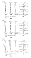
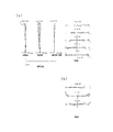
- FIG. 5A is a diagram illustrating various aberrations in the wide-angle end state of the variable magnification optical system according to the first example, where FIG. 9A is a diagram illustrating various aberrations when in the infinite focus state, and FIG. FIG. 10 is a lateral aberration diagram when camera shake correction is performed.
- FIG. 4A is a diagram illustrating various aberrations in the intermediate focal length state of the variable magnification optical system according to the first example, where FIG. 5A is a diagram illustrating various aberrations when the zoom lens is in the infinite focus state, and FIG. FIG. 6 is a lateral aberration diagram when camera shake correction is performed in FIG. FIG.
- FIG. 5A is a diagram illustrating various aberrations in the telephoto end state of the variable magnification optical system according to the first example, where FIG. 9A is a diagram illustrating various aberrations in the infinite focus state, and FIG. FIG. 10 is a lateral aberration diagram when camera shake correction is performed.
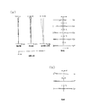
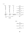
- FIG. 5A is a diagram illustrating various aberrations of the zoom optical system according to the first example in a close-up focus state, where FIG. 9A is a diagram illustrating various aberrations when the zoom lens is in the wide-angle end state, and FIG. FIG. 4C is a diagram illustrating various aberrations in the telephoto end state. It is sectional drawing which shows the lens structure of the variable magnification optical system which concerns on 2nd Example.
- FIG. 9A is a diagram illustrating various aberrations in the infinite focus state
- FIG. 10 is a lateral aberration diagram when camera shake correction is performed.
- FIG. 5A is a diagram illustrating various aberrations of the zoom optical system according to
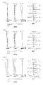
- FIG. 6A is a diagram illustrating various aberrations in the wide-angle end state of the variable magnification optical system according to the second example, where FIG. 9A is a diagram illustrating all aberrations in the infinite focus state, and FIG. FIG. 10 is a lateral aberration diagram when camera shake correction is performed.
- FIG. 7A is a diagram illustrating various aberrations in the intermediate focal length state of the variable magnification optical system according to the second example, where FIG. 9A is a diagram illustrating various aberrations when in the infinite focus state, and FIG. FIG. 6 is a lateral aberration diagram when camera shake correction is performed in FIG.
- FIG. 6A is a diagram illustrating various aberrations in the telephoto end state of the variable magnification optical system according to the second example, where FIG.
- FIG. 9A is a diagram illustrating various aberrations when in the infinite focus state
- FIG. FIG. 10 is a lateral aberration diagram when camera shake correction is performed.
- FIG. 9A is a diagram illustrating various aberrations of the zoom optical system according to Example 2 in a close-up focus state
- FIG. 9A is a diagram illustrating all aberrations when the zoom lens is in the wide-angle end state
- FIG. 4C is a diagram illustrating various aberrations in the telephoto end state.
- It is sectional drawing which shows the lens structure of the variable magnification optical system which concerns on 3rd Example.
- FIG. 7A is a diagram illustrating various aberrations in the wide-angle end state of the variable magnification optical system according to the third example, where FIG.
- FIG. 9A is a diagram illustrating various aberrations when in the infinite focus state
- FIG. FIG. 10 is a lateral aberration diagram when camera shake correction is performed.
- FIG. 6A is a diagram illustrating various aberrations in the intermediate focal length state of the variable magnification optical system according to the third example, where FIG. 9A is a diagram illustrating various aberrations when in the infinite focus state, and FIG. FIG. 6 is a lateral aberration diagram when camera shake correction is performed in FIG.
- FIG. 7A is a diagram illustrating various aberrations in the telephoto end state of the variable magnification optical system according to the third example, where FIG. 9A is a diagram illustrating various aberrations when in the infinite focus state, and FIG. FIG.
- FIG. 10 is a lateral aberration diagram when camera shake correction is performed.
- FIG. 9A is a diagram illustrating various aberrations of the zoom optical system according to Example 3 in a close-up focus state
- FIG. 9A is a diagram illustrating various aberrations when in the wide-angle end state
- FIG. 4C is a diagram illustrating various aberrations in the telephoto end state. It is sectional drawing of the camera carrying the said variable magnification optical system. It is a flowchart for demonstrating the manufacturing method of the said variable magnification optical system.
- variable magnification optical system ZL includes a first lens group G1 having a positive refractive power and a first lens having a negative refractive power in order from the object side along the optical axis. And a second lens group G2, a third lens group G3 having a positive refractive power, a fourth lens group G4 having a negative refractive power, and a fifth lens group G5 having a positive refractive power.
- a first lens group G1 having a positive refractive power and a first lens having a negative refractive power in order from the object side along the optical axis.
- a second lens group G2 a third lens group G3 having a positive refractive power
- a fourth lens group G4 having a negative refractive power
- a fifth lens group G5 having a positive refractive power.
- the zoom optical system ZL when the zoom is changed from the wide-angle end state to the telephoto end state, the distance between the first lens group G1 and the second lens group G2 changes, and the second lens group G2 and the third lens are changed.
- G1 to G5 move along the optical axis.
- the fifth lens group G5 includes at least one positive lens and one negative lens. With this configuration, it is possible to obtain good optical performance with a bright F-number lens.
- variable magnification optical system ZL satisfies the following conditional expression (1).
- f4 Focal length of the fourth lens group G4
- f5w Composite focal length of the image-side optical system including the fifth lens group G5 in the wide-angle end state
- Conditional expression (1) defines the ratio between the focal length of the fourth lens group G4 and the combined focal length of the optical system on the image side including the fifth lens group G5 in the wide-angle end state.
- f5w in the case of the five-group configuration as in the first and second embodiments described later is the focal length of the fifth lens group G5, and f5w in the case of the six-group configuration as in the third embodiment.
- the outer diameters of the third lens group G3 and the fourth lens group G4 can be reduced, and the lens barrel can be reduced in size. If the upper limit value of the conditional expression (1) is exceeded, the refractive power of the fifth lens group G5 becomes excessive, and the imaging performance deteriorates due to manufacturing errors, that is, the eccentric coma aberration and the eccentric image surface taole become excessive. It is not preferable. In order to secure the effect of the conditional expression (1), it is desirable to set the upper limit value of the conditional expression (1) to 2.00. In order to further secure the effect of the conditional expression (1), it is desirable to set the upper limit value of the conditional expression (1) to 1.40.
- the upper limit value of the conditional expression (1) is 1.10.
- the refractive power of the fourth lens group G4 becomes excessive, and the fluctuation of coma aberration at the time of zooming becomes excessive.
- the third lens group G3 has a large diameter, which increases the product diameter and excessively increases high-order spherical aberration, making correction difficult, which is not preferable.
- the lower limit value of the conditional expression (1) is 0.84.
- the lower limit value of the conditional expression (1) is 0.88.
- variable magnification optical system ZL satisfies the following conditional expression (2).
- FNw F number of the entire system in the wide-angle end state
- Conditional expression (2) defines the F number of the entire system of the variable magnification optical system ZL according to the present embodiment in the wide-angle end state. When this conditional expression (2) is satisfied, a large aperture can be obtained, and spherical aberration and the like can be corrected well. In order to secure the effect of the conditional expression (2), it is desirable to set the upper limit value of the conditional expression (2) to 3.30. In order to further secure the effect of the conditional expression (2), it is desirable to set the upper limit of the conditional expression (2) to 3.10. In order to further secure the effect of the conditional expression (2), it is desirable to set the upper limit value of the conditional expression (2) to 2.90.
- variable magnification optical system ZL satisfies the following conditional expressions (3) and (4).
- N5n Average value of refractive index for d-line of medium of all negative lenses in fifth lens group G5
- N5p Average value of refractive index for d-line of medium of all positive lenses in fifth lens group G5
- Conditional expressions (3) and (4) define the refractive index of the lens medium in the fifth lens group G5.
- the curvature of the lens surface in the fifth lens group G5 is reduced, and higher-order spherical aberration / coma, which becomes a problem when a large aperture and a large angle of view are obtained. It is possible to satisfactorily correct aberrations and curvature of field.
- the lower limit value of the conditional expression (4) is 1.86. In order to further secure the effect of the conditional expression (4), it is desirable to set the lower limit value of the conditional expression (4) to 1.88.
- variable magnification optical system ZL satisfies the following conditional expression (5).
- fw focal length of the entire system in the wide-angle end state
- ft focal length of the entire system in the telephoto end state
- Conditional expression (5) defines the ratio between the focal length of the entire system in the telephoto end state and the focal length of the entire system in the wide-angle end state, that is, the zoom ratio.
- this conditional expression (5) is satisfied, a high zoom ratio can be obtained, and spherical aberration and coma aberration can be corrected well.
- variable magnification optical system ZL satisfies the following conditional expression (6).
- FNt F number of the entire system in the telephoto end state
- Conditional expression (6) defines the F number of the entire system of the variable magnification optical system ZL according to the present embodiment in the telephoto end state. When this conditional expression (6) is satisfied, a large aperture can be obtained, and spherical aberration and the like can be corrected well.
- the upper limit value of the conditional expression (6) is 4.40.
- each lens group is configured to move along the optical axis.
- variable magnification optical system ZL satisfies the following conditional expression (7).
- f1 Focal length of the first lens group G1
- f3 Focal length of the third lens group G3
- Conditional expression (7) defines the ratio of the focal lengths of the first lens group G1 and the third lens group G3. Satisfying the conditional expression (7) makes it possible to achieve a well-balanced aberration correction at the time of increasing the diameter and the angle of view. If the upper limit value of the conditional expression (7) is exceeded, the refractive power of the third lens group G3 becomes excessive, and it becomes difficult to correct higher-order spherical aberration and coma as the diameter increases. Further, it is not preferable because the imaging performance is deteriorated due to a manufacturing error, that is, the decentered coma aberration and the decentered image plane taole are excessive.
- conditional expression (7) In order to secure the effect of the conditional expression (7), it is desirable to set the upper limit value of the conditional expression (7) to 4.00. In order to further secure the effect of the conditional expression (7), it is desirable to set the upper limit of the conditional expression (7) to 3.80. In order to further secure the effect of the conditional expression (7), it is desirable to set the upper limit value of the conditional expression (7) to 3.70.
- the lower limit value of conditional expression (7) if the lower limit value of conditional expression (7) is not reached, the refractive power of the first lens group G1 becomes excessive, and the fluctuation of the field curvature at the time of zooming becomes excessive. In addition, correction of higher-order field curvature becomes difficult as the angle of view increases.
- the first lens group G1 is not preferable because the diameter thereof is increased and the product diameter is increased.
- the lower limit value of the conditional expression (7) is 2.80.
- variable magnification optical system ZL satisfies the following conditional expression (8).
- f2 Focal length of the second lens group G2
- f4 Focal length of the fourth lens group G4
- Conditional expression (8) defines the ratio of the focal lengths of the second lens group G2 and the fourth lens group G4. Satisfying the conditional expression (8) makes it possible to achieve a well-balanced aberration correction at the time of increasing the diameter and the angle of view. If the upper limit value of the conditional expression (8) is exceeded, the refractive power of the fourth lens group G4 becomes excessive, and it becomes difficult to correct higher-order spherical aberration and coma aberration as the aperture becomes larger. Further, it is not preferable because the imaging performance is deteriorated due to a manufacturing error, that is, the decentered coma aberration and the decentered image plane taole are excessive.
- conditional expression (8) In order to secure the effect of the conditional expression (8), it is desirable to set the upper limit value of the conditional expression (8) to 0.50. In order to further secure the effect of the conditional expression (8), it is desirable to set the upper limit value of the conditional expression (8) to 0.45. In order to further secure the effect of the conditional expression (8), it is desirable to set the upper limit value of the conditional expression (8) to 0.40.
- the lower limit value of conditional expression (8) if the lower limit value of conditional expression (8) is not reached, the refractive power of the second lens group G2 becomes excessive, and the fluctuation of the field curvature at the time of zooming becomes excessive. In addition, correction of higher-order field curvature becomes difficult as the angle of view increases.
- the first lens group G1 is not preferable because the diameter thereof is increased and the product diameter is increased.
- the lower limit value of the conditional expression (8) is 0.28.
- variable magnification optical system ZL satisfies the following conditional expression (9).
- N2max the maximum value among the absolute values of the refractive index with respect to the d-line of the medium of the lens in the second lens group G2.
- Conditional expression (9) defines the refractive index of the lens medium in the second lens group G2. By satisfying this conditional expression (9), it is possible to suppress the variation in spherical aberration and coma during zooming. In order to secure the effect of the conditional expression (9), it is desirable to set the lower limit value of the conditional expression (9) to 1.86. In order to further secure the effect of the conditional expression (9), it is desirable to set the lower limit value of the conditional expression (9) to 1.88.
- variable magnification optical system ZL satisfies the following conditional expression (10).
- fw focal length of the entire system in the wide-angle end state
- f3 focal length of the third lens group G3
- Conditional expression (10) defines the ratio of the focal length of the entire zoom lens system ZL in the wide-angle end state to the focal length of the third lens group G3.
- conditional expression (10) it is desirable to set the upper limit value of the conditional expression (10) to 0.90. In order to further secure the effect of the conditional expression (10), it is desirable to set the upper limit value of the conditional expression (10) to 0.80. On the other hand, if the lower limit value of conditional expression (10) is not reached, the refractive power of the third lens group G3 becomes too small to ensure sufficient zooming.
- the refractive power of the first lens group G1, the second lens group G2, the fifth lens group G5, etc. becomes excessive, and fluctuations in field curvature during zooming and the fifth lens group. This is not desirable because aberration deterioration during manufacturing due to increased sensitivity of G5 becomes excessive.
- variable magnification optical system ZL satisfies the following conditional expression (11).
- Conditional expression (11) defines the ratio of the focal length of the entire variable magnification optical system ZL in the wide-angle end state to the focal length of the fourth lens group G4.
- the imaging performance is deteriorated due to a manufacturing error, that is, the decentered coma aberration and the decentered image plane taole are excessive.
- the upper limit value of the conditional expression (11) is 0.70.
- the refractive power of the fourth lens group G4 becomes too small to ensure sufficient zooming.
- the refractive power of the first lens group G1, the second lens group G2, the fifth lens group G5, etc. becomes excessive, and fluctuations in field curvature during zooming and the fifth lens group. This is not desirable because aberration deterioration during manufacturing due to increased sensitivity of G5 becomes excessive.
- the lower limit value of the conditional expression (11) is 0.35.
- variable magnification optical system ZL satisfies the following conditional expression (12).
- Conditional expression (12) defines the ratio of the focal length of the entire variable magnification optical system ZL in the telephoto end state to the focal length of the third lens group G3.
- the imaging performance is deteriorated due to a manufacturing error, that is, the decentered coma aberration and the decentered image plane taole are excessive.
- the refractive power of the first lens group G1, the second lens group G2, the fifth lens group G5, etc. becomes excessive, and fluctuations in field curvature during zooming and the fifth lens group. This is not desirable because aberration deterioration during manufacturing due to increased sensitivity of G5 becomes excessive.
- variable magnification optical system ZL satisfies the following conditional expression (13).
- Conditional expression (13) defines the ratio of the focal length of the entire variable magnification optical system ZL in the telephoto end state to the focal length of the fourth lens group G4.
- the imaging performance is deteriorated due to a manufacturing error, that is, the decentered coma aberration and the decentered image plane taole are excessive.
- the upper limit value of the conditional expression (13) is 4.00.
- the upper limit value of the conditional expression (13) is 3.50.
- the refractive power of the fourth lens group G4 becomes too small to ensure sufficient zooming.
- the refractive power of the first lens group G1, the second lens group G2, the fifth lens group G5, etc. becomes excessive, and fluctuations in field curvature during zooming and the fifth lens group. This is not desirable because aberration deterioration during manufacturing due to increased sensitivity of G5 becomes excessive.
- variable magnification optical system ZL satisfies the following conditional expressions (14) and (15).
- N3n Average value of refractive index for d-line of medium of all negative lenses in third lens group G3
- N3p Average value of refractive index for d-line of medium of all positive lenses in third lens group G3
- Conditional expressions (14) and (15) define the refractive index of the lens medium in the third lens group G3.
- the curvature of the lens surface in the third lens group G3 is reduced, and high-order spherical aberration, coma aberration and Thus, it is possible to satisfactorily correct aberration fluctuations.
- the lower limit value of the conditional expression (15) is 1.88.
- variable magnification optical system ZL satisfies the following conditional expression (16).
- Conditional expression (16) is a condition that defines an optimum value of the angle of view in the wide-angle end state. By satisfying conditional expression (16), it is possible to satisfactorily correct various aberrations such as coma, distortion, and field curvature while having a wide angle of view.
- the upper limit value of the conditional expression (16) is 50.0 °.
- the upper limit value of the conditional expression (16) is 45.0 °.
- the lower limit value of the conditional expression (16) is 30.0 °.
- the lower limit value of the conditional expression (16) is 35.0 °.
- variable magnification optical system ZL satisfies the following conditional expression (17).
- Conditional expression (17) is a condition for determining the optimum value of the angle of view in the telephoto end state. By satisfying this conditional expression (17), various aberrations such as coma, distortion, and field curvature can be favorably corrected.
- the upper limit value of the conditional expression (17) is 15.0 °.
- the upper limit value of the conditional expression (17) is 12.0 °.
- the lower limit value of the conditional expression (17) is 5.0 °.
- the lower limit value of the conditional expression (17) is 7.0 °. In order to further secure the effect of the conditional expression (17), it is desirable that the lower limit value of the conditional expression (17) is 8.0 °.
- variable magnification optical system ZL has an aspheric lens surface in the fifth lens group G5.
- variable magnification optical system ZL uses at least a part of the first lens group G1, the second lens group G2, the third lens group G3, the fourth lens group G4, and the fifth lens group G5 as light. It is desirable that the image position is corrected (anti-vibration) at the time of occurrence of camera shake by moving so as to have a displacement component in a direction orthogonal to the axis. Any one of these lens groups may be moved so as to have a displacement component in a direction perpendicular to the optical axis, or a part of any lens group or a lens group is perpendicular to the optical axis. You may move so that it may have a displacement component.
- variable magnification optical system ZL moves at least a part of the fourth lens group G4 so as to have a displacement component in a direction orthogonal to the optical axis. It is desirable to perform the correction (anti-vibration).
- the outer diameter of the lens can be reduced.
- the image stabilizing group is positioned near the middle of the aperture stop S and the image plane I, it is possible to suppress a change in light rays when the image position is corrected when camera shake occurs, and to reduce aberration fluctuation during camera shake correction. Is possible.
- the fourth lens group G4 includes a fourth A lens group G4A having a negative refractive power and a fourth B lens group G4B having a negative refractive power. Further, by correcting one of the fourth A lens group G4A and the fourth B lens group G4B so as to have a displacement component in a direction orthogonal to the optical axis, the image position can be corrected (anti-vibration) when camera shake occurs. it can. With such a configuration, various aberrations of the positive refracting power component generated in the third lens group G3 and the fifth lens group G5 when the image plane correction at the time of the occurrence of camera shake is performed are the fourth lens group G4. It is possible to correct by various aberrations of the negative refractive power component generated by the lens group that is not anti-vibrated, and it is possible to satisfactorily correct the aberration when the image surface correction is performed when camera shake occurs. .
- the third lens group G3 and the fifth lens group G5 move in the object direction during zooming from the wide-angle end state to the telephoto end state, and the image plane I It is desirable that the amount of movement with respect to be equal.
- the third lens group G3 and the fifth lens group G5 can be integrated, and the change in mutual eccentricity during zooming from the wide-angle end state to the telephoto end state can be suppressed. Degradation of optical performance due to errors can be mitigated.
- variable magnification optical system ZL is configured to move at least a part of the second lens group G2 along the optical axis when focusing on a short-distance object point. With such a configuration, it is possible to reduce the variation in spherical aberration and field curvature during focusing while reducing the outer diameter and weight of the focusing group.
- variable magnification optical system ZL has an aspheric lens surface in the fourth lens group G4.
- variable magnification optical system ZL has an aspheric lens surface in the second lens group G2.
- an antireflection film is provided on at least one of the optical surfaces in the lens group closest to the image side from the first lens group G1, and the antireflection film is
- nd at least one layer having an nd of 1.30 or less is included.
- variable magnification optical system ZL has an aperture stop, and the optical surface provided with the antireflection film is a concave lens surface when viewed from the aperture stop.
- the optical surfaces in the lens group closest to the image side from the first lens group G1 reflected light tends to be generated on a concave lens surface as viewed from the aperture stop. For this reason, a ghost and flare can be effectively reduced by forming an antireflection film on such a lens surface.
- the concave lens surface as viewed from the aperture stop is the object side lens surface of the lens in the first lens group G1.
- reflected light tends to be generated on a concave lens surface as viewed from the aperture stop. For this reason, a ghost and flare can be effectively reduced by forming an antireflection film on such a lens surface.
- the concave lens surface as viewed from the aperture stop is the image side lens surface of the lens in the first lens group G1.
- reflected light tends to be generated on a concave lens surface as viewed from the aperture stop. For this reason, a ghost and flare can be effectively reduced by forming an antireflection film on such a lens surface.
- the concave lens surface viewed from the aperture stop is the object side lens surface of the lens in the lens group closest to the image side.
- reflected light tends to be generated on a concave lens surface as viewed from the aperture stop. For this reason, a ghost and flare can be effectively reduced by forming an antireflection film on such a lens surface.
- the concave lens surface as viewed from the aperture stop is the image side lens surface of the lens in the lens group closest to the image side.
- reflected light tends to be generated on a concave lens surface as viewed from the aperture stop. For this reason, a ghost and flare can be effectively reduced by forming an antireflection film on such a lens surface.
- the optical surface provided with the antireflection film is a concave lens surface when viewed from the image side.
- the optical surfaces in the lens group closest to the image side and the first lens group G1 reflected light tends to be generated on a concave lens surface as viewed from the image side. For this reason, a ghost and flare can be effectively reduced by forming an antireflection film on such a lens surface.
- the concave lens surface as viewed from the image side is the object side lens surface of the lens in the lens group closest to the image side.
- reflected light tends to be generated on a concave lens surface as viewed from the image side. For this reason, a ghost and flare can be effectively reduced by forming an antireflection film on such a lens surface.
- the concave lens surface as viewed from the image side is the image side lens surface of the lens in the lens group closest to the image side.
- reflected light tends to be generated on a concave lens surface as viewed from the image side. For this reason, a ghost and flare can be effectively reduced by forming an antireflection film on such a lens surface.
- the optical surface provided with the antireflection film is a concave lens surface when viewed from the object.
- the optical surfaces in the lens group closest to the image side from the first lens group G1 reflected light tends to be generated on a concave lens surface as viewed from the object. For this reason, a ghost and flare can be effectively reduced by forming an antireflection film on such a lens surface.
- variable magnification optical system ZL it is desirable that the concave lens surface viewed from the object is the image side lens surface of the lens in the first lens group G1.
- reflected light tends to be generated on a concave lens surface as viewed from the object. For this reason, a ghost and flare can be effectively reduced by forming an antireflection film on such a lens surface.
- the antireflection film is a multilayer film
- the layer having a refractive index nd of 1.30 or less is the most surface layer among the layers constituting the multilayer film. It is desirable that With this configuration, the refractive index difference between the layer having a refractive index nd of 1.30 or less and air can be reduced, so that the reflection of light can be further reduced, and ghosts and flares can be further reduced. be able to.
- the antireflection film in the variable magnification optical system ZL according to the present embodiment may be formed by a wet process, a dry process, or the like.
- the antireflection film preferably includes at least one layer having a refractive index nd of 1.30 or less.
- the layer having a refractive index nd of 1.30 or less is preferably the most surface layer among the layers constituting the multilayer film.
- This camera 1 is a so-called mirrorless camera of interchangeable lens provided with a variable magnification optical system ZL according to the present embodiment as a photographing lens 2.
- OLPF Optical Low Pass Filter
- a subject image is formed on the screen.
- the subject image is photoelectrically converted by the photoelectric conversion element provided in the imaging unit 3 to generate an image of the subject.
- EVF Electronic view finder
- variable power optical system ZL is applied to a single-lens reflex camera that has a quick return mirror in the camera body and observes a subject with a finder optical system. Even when the camera is mounted, the same effect as the camera 1 can be obtained.
- variable magnification optical system ZL having a 5-group or 6-group configuration is shown, but the above-described configuration conditions and the like can be applied to other group configurations such as the 7-group and the 8-group.
- a configuration in which a lens or a lens group is added closest to the object side or a configuration in which a lens or a lens group is added closest to the image plane side may be used.
- a configuration in which a lens group whose position relative to the image plane is fixed at the time of zooming or focusing is added to the most image plane side.
- the lens group refers to a portion having at least one lens separated by an air interval that changes at the time of zooming or focusing.
- the first lens group G1 to the fifth lens group G5 each move along the optical axis so that the air spacing between the groups changes during zooming.
- the lens component refers to a single lens or a cemented lens in which a plurality of lenses are cemented.
- the focusing lens group may be a focusing lens group that performs focusing from an object at infinity to a short distance object by moving a single lens group, a plurality of lens groups, or a partial lens group in the optical axis direction.
- the focusing lens group can be applied to autofocus, and is also suitable for driving a motor for autofocus (such as an ultrasonic motor).
- a motor for autofocus such as an ultrasonic motor.
- the second lens group G2 is a focusing lens group, and the other lenses are fixed in position with respect to the image plane during focusing.
- the focusing lens group is composed of a single lens.
- the lens group or partial lens group is moved so as to have a displacement component perpendicular to the optical axis, or rotated (swinged) in the in-plane direction including the optical axis to correct image blur caused by camera shake.
- An anti-vibration lens group may be used.
- the lens surface may be formed of a spherical surface, a flat surface, or an aspheric surface.
- the lens surface is a spherical surface or a flat surface, lens processing and assembly adjustment are facilitated, and optical performance deterioration due to errors in processing and assembly adjustment can be prevented. Further, even when the image plane is deviated, it is preferable because there is little deterioration in drawing performance.
- the lens surface is an aspheric surface, the aspheric surface is an aspheric surface by grinding, a glass mold aspheric surface made of glass with an aspheric shape, or a composite aspheric surface made of resin with an aspheric shape on the glass surface. Any aspherical surface may be used.
- the lens surface may be a diffractive surface, and the lens may be a gradient index lens (GRIN lens) or a plastic lens.
- GRIN lens gradient index lens
- the aperture stop S is preferably disposed in the vicinity of or in the third lens group G3.
- the role of the aperture stop may be substituted by a lens frame without providing a member as an aperture stop.
- each lens surface may be provided with an antireflection film having a high transmittance in a wide wavelength region in order to reduce flare and ghost and achieve high optical performance with high contrast.
- the zoom optical system ZL of the present embodiment has a zoom ratio of about 3 to 10 times.
- each lens is arranged to prepare the first lens group G1, the second lens group G2, the third lens group G3, the fourth lens group G4, and the fifth lens group G5, respectively, from the wide-angle end state to the telephoto end state.
- the lens groups G1 to G5 are arranged so as to move along the optical axis so that the distance between the lens groups G1 to G5 changes (step S100).
- at least one positive lens and one negative lens are arranged in the fifth lens group G5 (step S200). And it arrange
- a cemented lens in which a negative meniscus lens L11 having a convex surface facing the object side and a biconvex lens L12 are cemented, and on the object side.
- a negative lens in which a positive meniscus lens L13 having a convex surface is arranged to form the first lens group G1, and a resin layer is provided on the object-side lens surface of a negative meniscus lens having a convex surface on the object side to form an aspherical shape.
- L21, a biconcave lens L22, a biconvex lens L23, and a negative meniscus lens L24 having a concave surface facing the object side are arranged as a second lens group G2, and an aperture stop S, a biconvex lens L31, a biconvex lens L32, and a concave surface on the object side
- a cemented lens that is cemented with a negative meniscus lens L33 facing the lens and a biconvex lens L34 are arranged to form a third lens group G3, and the lens surface on the object side has an aspherical shape.
- a fourth lens unit is formed by arranging a cemented lens in which a negative lens L41 having a biconcave lens shape and a positive meniscus lens L42 having a convex surface facing the object side are cemented, and a negative meniscus lens L43 having a concave surface facing the object side.
- G4 a planoconvex lens L51 having a plane facing the object side, and a cemented lens in which a biconvex lens L52 and a negative meniscus lens negative lens L53 in which the image side lens surface is formed in an aspherical shape are cemented are arranged.
- the lens groups thus prepared are arranged in the above-described procedure to manufacture the variable magnification optical system ZL.
- variable magnification optical system ZL having a compact and good optical performance
- an optical apparatus having the variable magnification optical system ZL and a method for manufacturing the variable magnification optical system ZL.
- variable magnification optical system ZL ZL1 to ZL3
- each lens group when changing magnification from the wide angle end state (W) to the telephoto end state (T) through the intermediate focal length state (M) is shown.
- the moving direction along the optical axis of G1 to G5 (or G6) is indicated by an arrow.
- the height of the aspheric surface in the direction perpendicular to the optical axis is y, and the distance (sag amount) along the optical axis from the tangential plane of the apex of each aspheric surface to each aspheric surface at height y.
- Is S (y) r is the radius of curvature of the reference sphere (paraxial radius of curvature)
- K is the conic constant
- An is the nth-order aspherical coefficient, it is expressed by the following equation (a). .
- “E ⁇ n” represents “ ⁇ 10 ⁇ n ”.
- the secondary aspheric coefficient A2 is zero.
- an aspherical surface is marked with * on the right side of the surface number.
- FIG. 1 is a diagram showing a configuration of a variable magnification optical system ZL1 according to the first example.
- the zoom optical system ZL1 shown in FIG. 1 includes, in order from the object side, a first lens group G1 having a positive refractive power, a second lens group G2 having a negative refractive power, and a first lens group having a positive refractive power.
- the third lens group G3 includes a third lens group G3, a fourth lens group G4 having a negative refractive power, and a fifth lens group G5 having a positive refractive power.
- the first lens group G1 includes, in order from the object side, a cemented lens in which a negative meniscus lens L11 having a convex surface facing the object side and a biconvex lens L12 are cemented, and a convex surface facing the object side.
- the second lens group G2 includes, in order from the object side, a negative lens L21 in which an aspherical shape is formed by providing a resin layer on a lens surface on the object side of a negative meniscus lens having a convex surface facing the object side, and a biconcave lens L22.
- the third lens group G3 includes, in order from the object side, a biconvex lens L31, a cemented lens in which the biconvex lens L32 and a negative meniscus lens L33 having a concave surface facing the object are cemented, and a biconvex lens L34.
- a negative lens L41 having a biconcave shape in which a lens surface on the object side is formed in an aspheric shape and a positive meniscus lens L42 having a convex surface directed toward the object side are cemented.
- the lens unit includes a 4A lens group G4A having negative refractive power that is a cemented lens, and a 4B lens group G4B having negative refractive power that is a negative meniscus lens L43 having a concave surface facing the object side.
- the fifth lens group G5 includes, in order from the object side, a planoconvex lens L51 having a plane directed toward the object side, and a negative meniscus lens negative shape in which a biconvex lens L52 and an image side lens surface are formed in an aspherical shape. It is composed of a cemented lens in which a lens L53 is cemented.
- the aperture stop S is disposed on the object side of the third lens group G3.
- the negative lens L41 and the negative lens L53 are glass molded aspheric lenses.
- variable magnification optical system ZL1 the distance between the first lens group G1 and the second lens group G2 increases during the magnification change from the wide-angle end state to the telephoto end state, and the second lens group G2 and the third lens group G3.
- Each lens group is light so that the distance between the third lens group G3 and the fourth lens group G4 increases and the distance between the fourth lens group G4 and the fifth lens group G5 decreases. It is configured to move to the object side along the axis.
- the aperture stop S moves integrally with the third lens group G3. Further, the third lens group G3 and the fifth lens group G5 are configured to have the same amount of movement with respect to the image plane.
- variable magnification optical system ZL1 focusing from an infinite distance to a short distance object point is performed by moving the second lens group G2 to the object side.
- variable magnification optical system ZL1 image position correction (anti-vibration) at the time of occurrence of camera shake moves the fourth lens group G4A of the fourth lens group G4 so as to have a displacement component in a direction orthogonal to the optical axis.
- the focal length of the entire system is f
- the image stabilization coefficient ratio of the amount of image movement on the imaging surface to the amount of movement of the 4A lens group G4A in correcting the image position when camera shake occurs
- the fourth-A lens group G4A which is the anti-vibration group, may be moved in the direction orthogonal to the optical axis by (f ⁇ tan ⁇ ) / K (the same applies to the following embodiments). is there).
- the fourth A for correcting the rotation blur of 0.50 °.
- the moving amount of the lens group G4A is -0.22 (mm).
- the image stabilization coefficient is ⁇ 0.79 and the focal length is 35.00 (mm), so that the rotational blur of 0.50 ° is corrected.
- the moving amount of the fourth A lens group G4A is -0.39 (mm). Further, in the telephoto end state of the first embodiment, the image stabilization coefficient is ⁇ 0.99 and the focal length is 77.79 (mm), so that it is necessary to correct a rotational shake of 0.50 °. The moving amount of the fourth A lens group G4A is ⁇ 0.68 (mm).
- Table 1 below lists the values of the specifications of the variable magnification optical system ZL1.
- f is the focal length of the entire system
- FNO is the F number
- ⁇ is the half field angle
- Y is the maximum image height
- TL is the full length
- BF is the back focus value. This is shown for each end state, intermediate focal length state, and telephoto end state.
- the total length TL indicates the distance on the optical axis from the most object side lens surface (first surface in FIG. 1) to the image plane I at the time of infinite focusing.
- the back focus BF indicates the distance (air conversion length) on the optical axis from the most image surface side lens surface (the 32nd surface in FIG. 1) to the image surface I at the time of focusing on infinity.
- the first column m indicates the order (surface number) of the lens surfaces from the object side along the traveling direction of the light beam
- the second column r indicates the curvature radius of each lens surface
- d is the distance on the optical axis from each optical surface to the next optical surface (surface interval).
- the surface numbers 1 to 32 shown in Table 1 correspond to the numbers m1 to m32 shown in FIG. 1 (only some surface numbers are shown in FIG. 1).
- the lens group focal length indicates the start surface and focal length of each of the first to fifth lens groups G1 to G5.
- the focal length f, the radius of curvature r, the surface interval d, and other length units listed in all the following specification values are generally “mm”, but the optical system is proportionally enlarged or proportional. Since the same optical performance can be obtained even if the image is reduced, the present invention is not limited to this.
- the description of these symbols and the description of the specification table are the same in the following embodiments.
- the sixth surface, the 23rd surface and the 32nd surface are formed in an aspherical shape.
- Table 2 below shows aspheric data, that is, the values of the conic constant K and the aspheric constants A4 to A12.
- variable magnification optical system ZL1 the axial air distance D5 between the first lens group G1 and the second lens group G2, and the axial air distance D14 between the second lens group G2 and the third lens group G3 (aperture stop S).
- the axial air gap D22 between the third lens group G3 and the fourth lens group G4, the axial air gap D27 between the fourth lens group G4 and the fifth lens group G5, and the back focus BF are as described above.
- Table 3 below shows variable intervals in the focal length states of the wide-angle end state (W), the intermediate focal length state (M), and the telephoto end state (T) in the infinitely focused state and the close-up focused state.
- D0 represents the distance from the most object-side surface (first surface) of the variable magnification optical system ZL1 to the object
- ⁇ represents the magnification (the same applies to the following examples).
- Table 4 below shows values corresponding to the conditional expressions in the variable magnification optical system ZL1.
- fw is the focal length of the entire system in the wide-angle end state
- ft is the focal length of the entire system in the telephoto end state
- f1 is the focal length of the first lens group G1
- f2 is the second lens group G2.
- F3 is the focal length of the third lens group G3
- f4 is the focal length of the fourth lens group G4
- f5w is the composite focal point of the image-side optical system including the fifth lens group G5 in the wide-angle end state.
- ⁇ w is the half field angle at the wide-angle end state
- ⁇ t is the half field angle at the telephoto end state
- FNw is the F-number of the entire system at the wide-angle end state
- FNt is the F-number of the entire system at the telephoto end state.
- N2max is the maximum value of the absolute value of the refractive index for the d-line of the lens medium in the second lens group G2
- N3n is the refractive index for the d-line of all the negative lens media in the third lens group G3.
- N3p is the third N5n is the average value of the refractive index for the d-line of the medium of all the positive lenses in the lens group G3, N5p is the average value of the refractive index for the d-line of the medium of all the negative lenses in the fifth lens group G5, The average values of the refractive indexes with respect to the d-line of the media of all the positive lenses in the fifth lens group G5 are respectively shown.
- the description of the reference numerals is the same in the following embodiments.
- the zoom optical system ZL1 satisfies all the conditional expressions (1) to (17).
- FIG. 2 is a spherical aberration diagram, astigmatism diagram, distortion diagram, magnification chromatic aberration diagram, and lateral aberration diagram in the wide-angle end state, the intermediate focal length state, and the telephoto end state of the variable magnification optical system ZL1 when focusing on infinity.
- FIGS. 3A and 4A are lateral aberration diagrams when image blur correction is performed in the wide-angle end state, the intermediate focal length state, and the telephoto end state when focusing on infinity. 2 (b), FIG. 3 (b), FIG. 4 (b), spherical aberration diagrams, astigmatism diagrams, distortion diagrams in the wide-angle end state, the intermediate focal length state, and the telephoto end state at the close focus.
- the lateral chromatic aberration diagram and lateral aberration diagram are shown in FIGS. 5 (a) to 5 (c).
- FNO is an F number
- A is a half angle of view (unit is [°])
- NA is a numerical aperture
- H0 is an object height.
- the spherical aberration diagram shows the F-number or numerical aperture value corresponding to the maximum aperture
- the astigmatism diagram and the distortion diagram show the half field angle or the maximum object height
- the lateral aberration diagram shows each half image.
- the value of a corner or each object height is shown.
- the solid line indicates the sagittal image plane
- the broken line indicates the meridional image plane.
- the same reference numerals as in this example are used in the aberration diagrams of the examples shown below. From these respective aberration diagrams, it can be seen that in the variable magnification optical system ZL1, various aberrations are satisfactorily corrected from the wide-angle end state to the telephoto end state.
- FIG. 6 is a diagram illustrating a configuration of the variable magnification optical system ZL2 according to the second example.
- the zoom optical system ZL2 shown in FIG. 6 includes, in order from the object side, a first lens group G1 having a positive refractive power, a second lens group G2 having a negative refractive power, and a first lens group having a positive refractive power.
- the third lens group G3 includes a third lens group G3, a fourth lens group G4 having a negative refractive power, and a fifth lens group G5 having a positive refractive power.
- the first lens group G1 includes, in order from the object side, a cemented lens in which a negative meniscus lens L11 having a convex surface facing the object side and a biconvex lens L12 are cemented, and a convex surface facing the object side.
- the second lens group G2 includes, in order from the object side, a negative lens L21 in which an aspherical shape is formed by providing a resin layer on a lens surface on the object side of a negative meniscus lens having a convex surface facing the object side, and a biconcave lens L22.
- the third lens group G3 includes, in order from the object side, a biconvex lens L31, a cemented lens in which the biconvex lens L32 and a negative meniscus lens L33 having a concave surface facing the object are cemented, and a biconvex lens L34.
- a negative lens L41 having a biconcave shape in which a lens surface on the object side is formed in an aspheric shape and a positive meniscus lens L42 having a convex surface directed toward the object side are cemented.
- the lens unit includes a 4A lens group G4A having negative refractive power that is a cemented lens, and a 4B lens group G4B having negative refractive power that is a negative meniscus lens L43 having a concave surface facing the object side.
- the fifth lens group G5 includes, in order from the object side, a biconvex lens L51, a negative meniscus lens L52 having a convex surface directed toward the object side, and a biconvex lens-shaped positive lens in which the image side lens surface is formed in an aspherical shape. It is composed of a lens L53.
- the aperture stop S is disposed on the object side of the third lens group G3.
- the negative lens L41 and the positive lens L53 are glass molded aspheric lenses.
- variable magnification optical system ZL2 the distance between the first lens group G1 and the second lens group G2 increases during the magnification change from the wide-angle end state to the telephoto end state, and the second lens group G2 and the third lens group G3.
- Each lens group is light so that the distance between the third lens group G3 and the fourth lens group G4 increases and the distance between the fourth lens group G4 and the fifth lens group G5 decreases. It is configured to move to the object side along the axis.
- the aperture stop S moves integrally with the third lens group G3. Further, the third lens group G3 and the fifth lens group G5 are configured to have the same amount of movement with respect to the image plane.
- variable magnification optical system ZL2 focusing from an infinite distance to a short-distance object point is performed by moving the second lens group G2 to the object side.
- the image position correction (anti-vibration) at the time of occurrence of camera shake moves the fourth lens group G4A of the fourth lens group G4 so as to have a displacement component in a direction perpendicular to the optical axis.
- the fourth A for correcting the rotation blur of 0.50 ° In the wide-angle end state of the second embodiment, since the image stabilization coefficient is ⁇ 0.68 and the focal length is 17.92 (mm), the fourth A for correcting the rotation blur of 0.50 °.
- the moving amount of the lens group G4A is ⁇ 0.23 (mm).
- the image stabilization coefficient is ⁇ 0.78 and the focal length is 32.00 (mm), so that the 0.50 ° rotational blur is corrected.
- the moving amount of the fourth A lens group G4A is -0.36 (mm). Further, in the telephoto end state of the second embodiment, the image stabilization coefficient is ⁇ 1.01 and the focal length is 83.00 (mm), so that it is necessary to correct a rotational shake of 0.50 °. The moving amount of the fourth A lens group G4A is ⁇ 0.72 (mm).
- Table 5 below lists the values of the specifications of the variable magnification optical system ZL2. Note that the surface numbers 1 to 33 shown in Table 5 correspond to the numbers m1 to m33 shown in FIG. 6 (only some surface numbers are shown in FIG. 6).
- the sixth surface, the 23rd surface and the 33rd surface are formed in an aspherical shape.
- Table 6 below shows the aspheric data, that is, the values of the conic constant K and the aspheric constants A4 to A12.
- variable magnification optical system ZL2 the axial air distance D5 between the first lens group G1 and the second lens group G2, and the axial air distance D14 between the second lens group G2 and the third lens group G3 (aperture stop S).
- the axial air gap D22 between the third lens group G3 and the fourth lens group G4, the axial air gap D27 between the fourth lens group G4 and the fifth lens group G5, and the back focus BF are as described above.
- Table 7 below shows variable intervals in the focal length states of the wide-angle end state (W), the intermediate focal length state (M), and the telephoto end state (T) in the infinitely focused state and the close-up focused state.
- Table 8 shows values corresponding to the conditional expressions in the variable magnification optical system ZL2.
- the zoom optical system ZL2 satisfies all the conditional expressions (1) to (17).
- FIG. 7 shows spherical aberration diagrams, astigmatism diagrams, distortion diagrams, magnification chromatic aberration diagrams, and lateral aberration diagrams of the variable magnification optical system ZL2 in the wide-angle end state, the intermediate focal length state, and the telephoto end state at the time of focusing on infinity.
- FIG. 8 (a), and FIG. 9 (a) are diagrams showing lateral aberrations when image blur correction is performed in the wide-angle end state, the intermediate focal length state, and the telephoto end state when focusing on infinity. 7 (b), FIG. 8 (b), and FIG.
- FIGS. 10 (a) to 10 (c) From these aberration diagrams, it is understood that various aberrations are satisfactorily corrected from the wide-angle end state to the telephoto end state in the variable magnification optical system ZL2.
- FIG. 11 is a diagram illustrating a configuration of the variable magnification optical system ZL3 according to the third example.
- the zoom optical system ZL3 shown in FIG. 11 includes, in order from the object side, a first lens group G1 having a positive refractive power, a second lens group G2 having a negative refractive power, and a first lens group having a positive refractive power.
- the third lens group G3 includes a fourth lens group G4 having a negative refractive power, a fifth lens group G5 having a positive refractive power, and a sixth lens group G6 having a positive refractive power. .
- the first lens group G1 includes, in order from the object side, a cemented lens in which a negative meniscus lens L11 having a convex surface facing the object side and a biconvex lens L12 are cemented, and a convex surface facing the object side.
- the second lens group G2 includes, in order from the object side, a negative lens L21 in which an aspherical shape is formed by providing a resin layer on a lens surface on the object side of a negative meniscus lens having a convex surface facing the object side, and a biconcave lens L22.
- the third lens group G3 includes, in order from the object side, a biconvex lens L31, a cemented lens in which the biconvex lens L32 and a negative meniscus lens L33 having a concave surface facing the object are cemented, and a biconvex lens L34.
- a negative lens L41 having a biconcave shape in which a lens surface on the object side is formed in an aspheric shape and a positive meniscus lens L42 having a convex surface directed toward the object side are cemented.
- the lens unit includes a 4A lens group G4A having negative refractive power that is a cemented lens, and a 4B lens group G4B having negative refractive power that is a negative meniscus lens L43 having a concave surface facing the object side.
- the fifth lens group G5 includes, in order from the object side, a biconvex lens L51, a biconvex positive lens L52 having an aspheric lens surface on the object side, and a negative meniscus lens L53 having a concave surface on the object side. Is composed of a cemented lens.
- the sixth lens group G6 includes a positive lens L61 having a positive meniscus lens shape with an image-side lens surface formed in an aspherical shape and a concave surface directed toward the object side.
- the aperture stop S is disposed on the object side of the third lens group G3.
- the negative lens L41, the positive lens L52, and the positive lens L61 are glass molded aspheric lenses.
- variable magnification optical system ZL3 when the magnification is changed from the wide-angle end state to the telephoto end state, the distance between the first lens group G1 and the second lens group G2 increases, and the second lens group G2 and the third lens group G3.
- the distance between the third lens group G3 and the fourth lens group G4 increases, the distance between the fourth lens group G4 and the fifth lens group G5 decreases, and the fifth lens group G5 and the fifth lens group G5
- Each lens group is configured to move toward the object side along the optical axis so that the distance from the six lens groups G6 increases.
- the aperture stop S moves integrally with the third lens group G3. Further, the third lens group G3 and the fifth lens group G5 are configured to have the same amount of movement with respect to the image plane.
- variable magnification optical system ZL3 focusing from an infinite distance to a short-distance object point is performed by moving the second lens group G2 to the object side.
- the correction of image position (anti-shake) at the time of occurrence of camera shake moves the fourth lens group G4A of the fourth lens group G4 so as to have a displacement component in a direction perpendicular to the optical axis.
- the image stabilization coefficient is ⁇ 0.67 and the focal length is 18.60 (mm). Therefore, the fourth A for correcting the rotation blur of 0.50 °.
- the moving amount of the lens group G4A is ⁇ 0.24 (mm).
- the image stabilization coefficient is ⁇ 0.76 and the focal length is 31.80 (mm), so that the rotational blur of 0.50 ° is corrected.
- the moving amount of the fourth A lens group G4A is -0.37 (mm). Further, in the telephoto end state of the third embodiment, the image stabilization coefficient is ⁇ 0.95 and the focal length is 77.81 (mm), so that it is possible to correct a rotational shake of 0.50 °. The moving amount of the fourth A lens group G4A is ⁇ 0.71 (mm).
- Table 9 below lists values of specifications of the variable magnification optical system ZL3.
- the surface numbers 1 to 34 shown in Table 9 correspond to the numbers m1 to m34 shown in FIG. 11 (note that only some surface numbers are shown in FIG. 11).
- the sixth surface, the 23rd surface, the 30th surface and the 34th surface are formed in an aspherical shape.
- Table 10 below shows the aspheric data, that is, the values of the conical constant K and the aspheric constants A4 to A12.
- variable magnification optical system ZL3 In the variable magnification optical system ZL3, the axial air distance D5 between the first lens group G1 and the second lens group G2, and the axial air distance D14 between the second lens group G2 and the third lens group G3 (aperture stop S).
- Table 11 shows the variable intervals in each of the focal length states of the wide-angle end state (W), the intermediate focal length state (M), and the telephoto end state (T) in the infinitely focused state and the closest focused state.
- Table 12 shows values corresponding to the conditional expressions in the variable magnification optical system ZL3.
- variable magnification optical system ZL3 satisfies all the conditional expressions (1) to (17).
- FIG. 12 shows spherical aberration diagrams, astigmatism diagrams, distortion diagrams, magnification chromatic aberration diagrams, and lateral aberration diagrams of the variable magnification optical system ZL3 in the wide-angle end state, the intermediate focal length state, and the telephoto end state at the time of focusing on infinity.
- FIGS. 13A and 14A are lateral aberration diagrams when image blur correction is performed in the wide-angle end state, the intermediate focal length state, and the telephoto end state when focusing on infinity. 12 (b), FIG. 13 (b), and FIG.
- FIGS. 14 (b) spherical aberration diagrams, astigmatism diagrams, distortion diagrams in the wide-angle end state, the intermediate focal length state, and the telephoto end state at the close focus.
- the lateral chromatic aberration diagram and lateral aberration diagram are shown in FIGS. From these respective aberration diagrams, it can be seen that various aberrations are satisfactorily corrected from the wide-angle end state to the telephoto end state in the variable magnification optical system ZL3.
Landscapes
- Physics & Mathematics (AREA)
- General Physics & Mathematics (AREA)
- Optics & Photonics (AREA)
- Lenses (AREA)
- Nonlinear Science (AREA)
- Adjustment Of Camera Lenses (AREA)
- Surface Treatment Of Optical Elements (AREA)
Abstract
Description
0.80 < (-f4)/f5w < 2.50
FNw < 3.50
但し、
f4:第4レンズ群の焦点距離
f5w:広角端状態における第5レンズ群を含む像側の光学系の合成焦点距離
FNw:広角端状態における全系のFナンバー
0.80 < (-f4)/f5w < 2.50
FNw < 3.50
但し、
f4:第4レンズ群の焦点距離
f5w:広角端状態における第5レンズ群を含む像側の光学系の合成焦点距離
FNw:広角端状態における全系のFナンバー
但し、
f4:第4レンズ群G4の焦点距離
f5w:広角端状態における第5レンズ群G5を含む像側の光学系の合成焦点距離
但し、
FNw:広角端状態における全系のFナンバー
1.85 < N5n (4)
但し、
N5n:第5レンズ群G5中の全ての負レンズの媒質のd線に対する屈折率の平均値
N5p:第5レンズ群G5中の全ての正レンズの媒質のd線に対する屈折率の平均値
但し、
fw:広角端状態における全系の焦点距離
ft:望遠端状態における全系の焦点距離
但し、
FNt:望遠端状態における全系のFナンバー
但し、
f1:第1レンズ群G1の焦点距離
f3:第3レンズ群G3の焦点距離
但し、
f2:第2レンズ群G2の焦点距離
f4:第4レンズ群G4の焦点距離
但し、
N2max:第2レンズ群G2中のレンズの媒質のd線に対する屈折率の絶対値のうちの最大値
但し、
fw:広角端状態における全系の焦点距離
f3:第3レンズ群G3の焦点距離
但し、
fw:広角端状態における全系の焦点距離
f4:第4レンズ群G4の焦点距離
但し、
ft:望遠端状態における全系の焦点距離
f3:第3レンズ群G3の焦点距離
但し
ft:望遠端状態における全系の焦点距離
f4:第4レンズ群G4の焦点距離
1.85 < N3n (15)
但し、
N3n:第3レンズ群G3中の全ての負レンズの媒質のd線に対する屈折率の平均値
N3p:第3レンズ群G3中の全ての正レンズの媒質のd線に対する屈折率の平均値
但し、
ωw:広角端状態における半画角
但し、
ωt:望遠端状態における半画角
+A4×y4+A6×y6+A8×y8+A10×y10+A12×y12 (a)
図1は、第1実施例に係る変倍光学系ZL1の構成を示す図である。この図1に示す変倍光学系ZL1は、物体側から順に、正の屈折力を有する第1レンズ群G1と、負の屈折力を有する第2レンズ群G2と、正の屈折力を有する第3レンズ群G3と、負の屈折力を有する第4レンズ群G4と、正の屈折力を有する第5レンズ群G5と、から構成されている。
[全体諸元]
広角端状態 中間焦点距離状態 望遠端状態
f = 16.49 ~ 35.00 ~ 77.79
FNo = 2.72 ~ 3.38 ~ 4.16
ω = 43.2 ~ 22.0 ~ 10.4
Y = 14.75 ~ 14.75 ~ 14.75
TL = 130.371 ~ 146.181 ~ 171.571
BF = 37.994 ~ 49.378 ~ 63.528
BF(空気換算長)= 37.994 ~ 49.378 ~ 63.528
[レンズデータ]
m r d nd νd
物面 ∞
1 142.08408 1.800 1.84666 23.8
2 61.98900 6.800 1.59319 67.9
3 2234.55748 0.100
4 54.61907 4.400 1.81600 46.6
5 160.87634 D5
6* 111.35036 0.200 1.56093 36.6
7 74.66256 1.200 1.81600 46.6
8 13.29818 6.450
9 -26.94042 1.000 1.81600 46.6
10 41.14663 0.800
11 38.15106 4.500 1.84666 23.8
12 -28.49989 0.500
13 -21.99346 1.000 1.88300 40.7
14 -53.69291 D14
15 0.00000 1.600 開口絞りS
16 237.40240 3.500 1.54814 45.8
17 -29.52544 0.150
18 41.68613 4.200 1.51742 52.2
19 -26.94900 1.100 1.90200 25.3
20 -425.16586 0.100
21 37.61777 2.850 1.49782 82.6
22 -64.06628 D22
23* -69.82119 0.800 1.79050 45.0
24 24.82010 2.000 1.90200 25.3
25 100.53108 2.550
26 -22.07831 1.000 1.81600 46.6
27 -33.57787 D27
28 0.00000 4.600 1.49782 82.6
29 -20.99670 0.100
30 71.45078 6.100 1.49782 82.6
31 -20.04840 1.200 1.88202 37.2
32* -55.06437 BF
像面 ∞
[レンズ群焦点距離]
レンズ群 始面 焦点距離
第1レンズ群 1 86.49
第2レンズ群 6 -13.10
第3レンズ群 15 24.85
第4レンズ群 23 -35.11
第5レンズ群 28 36.01
[非球面データ]
第 6面 K= 1.00000e+00
A4 A6 A8 A10 A12
1.91866e-05 -3.07743e-08 -1.44905e-10 1.15106e-12 -1.98690e-15
第23面 K= 1.00000e+00
A4 A6 A8 A10 A12
3.75789e-06 -1.80254e-08 0.00000e+00 0.00000e+00 0.00000e+00
第32面 K= 1.00000e+00
A4 A6 A8 A10 A12
7.46360e-06 8.05331e-09 -4.65179e-11 2.16314e-13 0.00000e+00
[可変間隔データ]
無限遠 至近
W M T W M T
D0 ∞ ∞ ∞ 219.63 203.82 178.43
β - - - -0.0648 -0.1260 -0.2249
f 16.49 35.00 77.79 - - -
D5 2.100 17.730 35.502 0.885 15.776 31.579
D14 18.846 7.642 1.110 20.061 9.596 5.033
D22 1.434 6.306 9.411 1.434 6.306 9.411
D27 9.397 4.525 1.420 9.397 4.525 1.420
BF 37.994 49.378 63.528 37.994 49.378 63.528
f5w=36.01
[条件式対応値]
(1)(-f4)/f5w=0.975
(2)FNw=2.722
(3)N5n-N5p=0.384
(4)N5n=1.882
(5)ft/fw=4.717
(6)FNt=4.160
(7)f1/f3=3.480
(8)f2/f4=0.371
(9)N2max=1.883
(10)fw/f3=0.664
(11)fw/(-f4)=0.470
(12)ft/f3=3.130
(13)ft/(-f4)=2.216
(14)N3n-N3p=0.381
(15)N3n=1.902
(16)ωw=43.244
(17)ωt=10.411
図6は、第2実施例に係る変倍光学系ZL2の構成を示す図である。この図6に示す変倍光学系ZL2は、物体側から順に、正の屈折力を有する第1レンズ群G1と、負の屈折力を有する第2レンズ群G2と、正の屈折力を有する第3レンズ群G3と、負の屈折力を有する第4レンズ群G4と、正の屈折力を有する第5レンズ群G5と、から構成されている。
[全体諸元]
広角端状態 中間焦点距離状態 望遠端状態
f = 17.92 ~ 32.00 ~ 83.00
FNo = 2.44 ~ 2.92 ~ 3.77
ω = 40.0 ~ 23.4 ~ 9.5
Y = 14.25 ~ 14.25 ~ 14.25
TL = 132.419 ~ 144.654 ~ 174.652
BF = 41.537 ~ 49.713 ~ 65.542
BF(空気換算長)= 41.537 ~ 49.713 ~ 65.542
[レンズデータ]
m r d nd νd
物面 ∞
1 167.51126 1.800 1.84666 23.8
2 65.36598 6.800 1.59319 67.9
3 -2500.00000 0.100
4 53.28844 4.400 1.81600 46.6
5 148.73119 D5
6* 98.04448 0.200 1.56093 36.6
7 60.00000 1.200 1.80400 46.6
8 14.40723 6.471
9 -27.00000 1.000 1.81600 46.6
10 49.41381 0.749
11 42.76510 4.500 1.84666 23.8
12 -29.37797 1.000
13 -19.04811 1.000 1.88300 40.7
14 -46.90749 D14
15 0.00000 0.400 開口絞りS
16 436.00582 2.927 1.54814 45.8
17 -30.11148 0.150
18 59.43487 4.000 1.48749 70.3
19 -28.97361 1.100 1.90200 25.3
20 -62.61619 0.100
21 56.98362 2.750 1.49782 82.6
22 -76.57983 D22
23* -41.28693 0.800 1.79050 45.0
24 37.52861 2.000 1.90200 25.3
25 -3339.51980 3.000
26 -26.16246 1.000 1.72916 54.6
27 -49.02058 D27
28 36.11715 4.600 1.49782 82.6
29 -43.89441 0.100
30 67.43312 1.200 1.91748 28.6
31 25.37662 1.310
32 37.12949 4.271 1.49786 82.5
33* -39.01900 BF
像面 ∞
[レンズ群焦点距離]
レンズ群 始面 焦点距離
第1レンズ群 1 87.89
第2レンズ群 6 -13.10
第3レンズ群 15 24.40
第4レンズ群 23 -33.98
第5レンズ群 28 36.22
[非球面データ]
第 6面 K= 1.00000e+00
A4 A6 A8 A10 A12
1.85470e-05 -4.02525e-08 2.54277e-10 -1.05685e-12 3.80620e-15
第23面 K= 1.00000e+00
A4 A6 A8 A10 A12
3.85870e-06 6.25371e-10 0.00000e+00 0.00000e+00 0.00000e+00
第33面 K= -3.93240e+00
A4 A6 A8 A10 A12
2.65953e-06 1.69344e-08 -8.71281e-13 1.49597e-13 0.00000e+00
[可変間隔データ]
無限遠 至近
W M T W M T
D0 ∞ ∞ ∞ 217.58 205.35 175.35
β - - - -0.0704 -0.1176 -0.2335
f 17.92 32.00 83.00 - - -
D5 2.650 15.012 36.908 1.386 13.195 32.734
D14 18.429 10.126 2.400 19.693 11.944 6.574
D22 1.400 5.657 9.876 1.400 5.657 9.876
D27 9.476 5.219 1.000 9.476 5.219 1.000
BF 41.537 49.713 65.542 41.537 49.713 65.542
f5w=36.22
[条件式対応値]
(1)(-f4)/f5w=0.938
(2)FNw=2.443
(3)N5n-N5p=0.420
(4)N5n=1.917
(5)ft/fw=4.632
(6)FNt=3.769
(7)f1/f3=3.602
(8)f2/f4=0.385
(9)N2max=1.883
(10)fw/f3=0.734
(11)fw/(-f4)=0.527
(12)ft/f3=3.401
(13)ft/(-f4)=2.442
(14)N3n-N3p=0.391
(15)N3n=1.902
(16)ωw=39.990
(17)ωt=9.463
図11は、第3実施例に係る変倍光学系ZL3の構成を示す図である。この図11に示す変倍光学系ZL3は、物体側から順に、正の屈折力を有する第1レンズ群G1と、負の屈折力を有する第2レンズ群G2と、正の屈折力を有する第3レンズ群G3と、負の屈折力を有する第4レンズ群G4と、正の屈折力を有する第5レンズ群G5と、正の屈折力を有する第6レンズ群G6と、から構成されている。
[全体諸元]
広角端状態 中間焦点距離状態 望遠端状態
f = 18.60 ~ 31.80 ~ 77.81
FNo = 2.01 ~ 2.34 ~ 2.96
ω = 38.9 ~ 23.5 ~ 10.1
Y = 14.25 ~ 14.25 ~ 14.25
TL = 134.524 ~ 147.355 ~ 176.966
BF = 38.015 ~ 45.607 ~ 60.406
BF(空気換算長)= 38.015 ~ 45.607 ~ 60.406
[レンズデータ]
m r d nd νd
物面 ∞
1 160.52802 1.800 1.84666 23.8
2 65.03652 6.800 1.59319 67.9
3 -2500.00000 0.100
4 52.64606 4.400 1.81600 46.6
5 143.14329 D5
6* 96.56216 0.200 1.56093 36.6
7 60.00000 1.200 1.80400 46.6
8 14.83792 6.143
9 -27.00000 1.000 1.81600 46.6
10 44.96605 0.853
11 43.56313 4.500 1.84666 23.8
12 -24.56322 0.812
13 -18.65534 1.000 1.88300 40.7
14 -61.97483 D14
15 0.00000 0.400 開口絞りS
16 159.25973 3.913 1.58913 61.2
17 -34.07018 0.150
18 47.41744 5.310 1.57479 62.2
19 -36.74413 1.100 1.90200 25.3
20 -177.06283 0.100
21 62.88551 3.778 1.49782 82.6
22 -66.42221 D22
23* -41.70870 0.800 1.79050 45.0
24 42.89444 2.100 1.90200 25.3
25 -2019.67150 3.000
26 -26.60428 1.000 1.72916 54.6
27 -53.45527 D27
28 1984.71100 4.800 1.50514 74.0
29 -25.14230 0.100
30* 64.22325 5.500 1.49782 82.6
31 -26.83334 1.200 1.88202 37.2
32 -326.49263 D32
33 -64.59872 3.428 1.49782 82.6
34* -25.07133 BF
像面 ∞
[レンズ群焦点距離]
レンズ群 始面 焦点距離
第1レンズ群 1 86.55
第2レンズ群 6 -13.10
第3レンズ群 15 23.83
第4レンズ群 23 -33.00
第5レンズ群 28 56.67
第6レンズ群 33 80.00
[非球面データ]
第 6面 K= 1.00000e+00
A4 A6 A8 A10 A12
1.75539e-05 -6.44055e-09 -1.64524e-10 1.05588e-12 6.14360e-16
第23面 K= 1.00000e+00
A4 A6 A8 A10 A12
5.80858e-06 -1.19924e-08 0.00000e+00 0.00000e+00 0.00000e+00
第30面 K= -1.79426e+01
A4 A6 A8 A10 A12
-7.47242e-06 1.89731e-08 -3.85325e-10 9.87434e-13 0.00000e+00
第34面 K= 4.62100e-01
A4 A6 A8 A10 A12
-7.86061e-07 2.71115e-08 -2.30871e-10 4.72584e-13 0.00000e+00
[可変間隔データ]
無限遠 至近
W M T W M T
D0 ∞ ∞ ∞ 215.48 202.64 173.03
β - - - -0.0737 -0.1184 -0.2280
f 18.60 31.80 77.81 - - -
D5 2.336 14.327 34.805 1.052 12.483 30.752
D14 17.818 10.066 2.400 19.102 11.910 6.452
D22 1.400 4.791 8.625 1.400 4.791 8.625
D27 8.224 4.833 1.000 8.224 4.833 1.000
D32 1.244 2.244 4.244 1.244 2.244 4.244
BF 38.015 45.607 60.406 38.015 45.607 60.406
f5w=36.20
[条件式対応値]
(1)(-f4)/f5w=0.912
(2)FNw=2.010
(3)N5n-N5p=0.381
(4)N5n=1.882
(5)ft/fw=4.183
(6)FNt=2.957
(7)f1/f3=3.631
(8)f2/f4=0.397
(9)N2max=1.883
(10)fw/f3=0.780
(11)fw/(-f4)=0.564
(12)ft/f3=3.265
(13)ft/(-f4)=2.358
(14)N3n-N3p=0.348
(15)N3n=1.902
(16)ωw=38.943
(17)ωt=10.081
G1 第1レンズ群 G2 第2レンズ群 G3 第3レンズ群
G4 第4レンズ群 G4A 第4Aレンズ群 G4B 第4Bレンズ群
G5 第5レンズ群
Claims (28)
- 光軸に沿って、物体側から順に、
正の屈折力を有する第1レンズ群と、
負の屈折力を有する第2レンズ群と、
正の屈折力を有する第3レンズ群と、
負の屈折力を有する第4レンズ群と、
正の屈折力を有する第5レンズ群と、を有し、
広角端状態から望遠端状態への変倍に際し、前記第1レンズ群と前記第2レンズ群との間隔が変化し、前記第2レンズ群と前記第3レンズ群との間隔が変化し、前記第3レンズ群と前記第4レンズ群との間隔が変化し、前記第4レンズ群と前記第5レンズ群との間隔が変化するように、各レンズ群が光軸に沿って移動し、
前記第5レンズ群は、正レンズ及び負レンズを少なくとも1枚ずつ有し、
次式の条件を満足することを特徴とする変倍光学系。
0.80 < (-f4)/f5w < 2.50
FNw < 3.50
但し、
f4:前記第4レンズ群の焦点距離
f5w:広角端状態における前記第5レンズ群を含む像側の光学系の合成焦点距離
FNw:広角端状態における全系のFナンバー - 次式の条件を満足することを特徴とする請求項1に記載の変倍光学系。
0.30 < N5n-N5p
1.85 < N5n
但し、
N5n:前記第5レンズ群中の全ての負レンズの媒質のd線に対する屈折率の平均値
N5p:前記第5レンズ群中の全ての正レンズの媒質のd線に対する屈折率の平均値 - 次式の条件を満足することを特徴とする請求項1または2に記載の変倍光学系。
3.50 < ft/fw
但し、
fw:広角端状態における全系の焦点距離
ft:望遠端状態における全系の焦点距離 - 次式の条件を満足することを特徴とする請求項1~3のいずれか一項に記載の変倍光学系。
FNt < 4.50
但し、
FNt:望遠端状態における全系のFナンバー - 広角端状態から望遠端状態に変倍する際に、
前記第1レンズ群と前記第2レンズ群との間隔が増大し、
前記第2レンズ群と前記第3レンズ群との間隔が減少し、
前記第3レンズ群と前記第4レンズ群との間隔が増大し、
前記第4レンズ群と前記第5レンズ群との間隔が減少するように、各レンズ群が光軸に沿って移動することを特徴とする請求項1~4のいずれか一項に記載の変倍光学系。 - 次式の条件を満足することを特徴とする請求項1~5のいずれか一項に記載の変倍光学系。
2.50 < f1/f3 < 4.20
但し、
f1:前記第1レンズ群の焦点距離
f3:前記第3レンズ群の焦点距離 - 次式の条件を満足することを特徴とする請求項1~6のいずれか一項に記載の変倍光学系。
0.25 < f2/f4 < 0.55
但し、
f2:前記第2レンズ群の焦点距離
f4:前記第4レンズ群の焦点距離 - 次式の条件を満足することを特徴とする請求項1~7のいずれか一項に記載の変倍光学系。
1.85 < N2max
但し、
N2max:前記第2レンズ群中のレンズの媒質のd線に対する屈折率の絶対値のうちの最大値 - 次式の条件を満足することを特徴とする請求項1~8のいずれか一項に記載の変倍光学系。
0.40 < fw/f3 < 1.00
但し、
fw:広角端状態における全系の焦点距離
f3:前記第3レンズ群の焦点距離 - 次式の条件を満足することを特徴とする請求項1~9のいずれか一項に記載の変倍光学系。
0.30 < fw/(-f4) < 0.80
但し、
fw:広角端状態における全系の焦点距離
f4:前記第4レンズ群の焦点距離 - 次式の条件を満足することを特徴とする請求項1~10のいずれか一項に記載の変倍光学系。
2.00 < ft/f3 < 5.00
但し、
ft:望遠端状態における全系の焦点距離
f3:前記第3レンズ群の焦点距離 - 次式の条件を満足することを特徴とする請求項1~11のいずれか一項に記載の変倍光学系。
1.50 < ft/(-f4) < 4.50
但し
ft:望遠端状態における全系の焦点距離
f4:前記第4レンズ群の焦点距離 - 次式の条件を満足することを特徴とする請求項1~12のいずれか一項に記載の変倍光学系。
0.30 < N3n-N3p
1.85 < N3n
但し、
N3n:前記第3レンズ群中の全ての負レンズの媒質のd線に対する屈折率の平均値
N3p:前記第3レンズ群中の全ての正レンズの媒質のd線に対する屈折率の平均値 - 次式の条件を満足することを特徴とする請求項1~13のいずれか一項に記載の変倍光学系。
25.0° < ωw < 60.0°
但し、
ωw:広角端状態における半画角 - 次式の条件を満足することを特徴とする請求項1~14のいずれか一項に記載の変倍光学系。
3.0° < ωt < 20.0°
但し、
ωt:望遠端状態における半画角 - 前記第5レンズ群は、非球面形状のレンズ面を有することを特徴とする請求項1~15のいずれか一項に記載の変倍光学系。
- 前記第1レンズ群、前記第2レンズ群、前記第3レンズ群、前記第4レンズ群及び前記第5レンズ群の少なくとも一部を、光軸と直交する方向の変位成分を持つように移動させることを特徴とする請求項1~16のいずれか一項に記載の変倍光学系。
- 前記第4レンズ群の少なくとも一部を、光軸と直交する方向の変位成分を持つように移動させることを特徴とする請求項17に記載の変倍光学系。
- 前記第4レンズ群は、
負の屈折力を有する第4Aレンズ群と、
負の屈折力を有する第4Bレンズ群と、を有し、
前記第4Aレンズ群及び前記第4Bレンズ群の一方を、光軸と直交する方向の変位成分を持つように移動させることを特徴とする請求項18に記載の変倍光学系。 - 広角端状態から望遠端状態への変倍に際し、前記第3レンズ群及び前記第5レンズ群は物体方向に移動し、且つ、像面に対する移動量が等しいことを特徴とする請求項1~19のいずれか一項に記載の変倍光学系。
- 近距離物点への合焦に際し、前記第2レンズ群の少なくとも一部を光軸に沿って移動させることを特徴とする請求項1~20のいずれか一項に記載の変倍光学系。
- 前記第4レンズ群は、非球面形状のレンズ面を有することを特徴とする請求項1~21のいずれか一項に記載の変倍光学系。
- 前記第2レンズ群は、非球面形状のレンズ面を有することを特徴とする請求項1~22のいずれか一項に記載の変倍光学系。
- 前記第1レンズ群から最も像側のレンズ群における光学面のうちの少なくとも1面に反射防止膜が設けられており、
前記反射防止膜は、d線(波長λ=587.6nm)に対する屈折率をndとしたとき、ndが1.30以下である層を少なくとも1層含むことを特徴とする請求項1~23のいずれか一項に記載の変倍光学系。 - 開口絞りを有し、
前記反射防止膜が設けられた前記光学面は、前記開口絞りから見て凹形状のレンズ面であることを特徴とする請求項24に記載の変倍光学系。 - 前記反射防止膜が設けられた前記光学面は、像側から見て凹形状のレンズ面であることを特徴とする請求項24または25に記載の変倍光学系。
- 請求項1~26のいずれか一項に記載の変倍光学系を有することを特徴とする光学機器。
- 光軸に沿って、物体側から順に、正の屈折力を有する第1レンズ群と、負の屈折力を有する第2レンズ群と、正の屈折力を有する第3レンズ群と、負の屈折力を有する第4レンズ群と、正の屈折力を有する第5レンズ群と、を有する変倍光学系の製造方法であって、
広角端状態から望遠端状態への変倍に際し、前記第1レンズ群と前記第2レンズ群との間隔が変化し、前記第2レンズ群と前記第3レンズ群との間隔が変化し、前記第3レンズ群と前記第4レンズ群との間隔が変化し、前記第4レンズ群と前記第5レンズ群との間隔が変化するように、各レンズ群が光軸に沿って移動するように配置し、
前記第5レンズ群に、正レンズ及び負レンズを少なくとも1枚ずつ配置し、
次式の条件を満足するように配置することを特徴とする変倍光学系の製造方法。
0.80 < (-f4)/f5w < 2.50
FNw < 3.50
但し、
f4:前記第4レンズ群の焦点距離
f5w:広角端状態における前記第5レンズ群を含む像側の光学系の合成焦点距離
FNw:広角端状態における全系のFナンバー
Priority Applications (4)
| Application Number | Priority Date | Filing Date | Title |
|---|---|---|---|
| US15/575,399 US10782512B2 (en) | 2015-05-29 | 2016-05-27 | Zoom optical system, optical device and method for manufacturing the zoom optical system |
| CN201680031513.6A CN107615130B (zh) | 2015-05-29 | 2016-05-27 | 变倍光学系统以及光学设备 |
| JP2017521899A JP6645498B2 (ja) | 2015-05-29 | 2016-05-27 | 変倍光学系及び光学機器 |
| US17/022,018 US11415788B2 (en) | 2015-05-29 | 2020-09-15 | Zoom optical system, optical device and method for manufacturing the zoom optical system |
Applications Claiming Priority (2)
| Application Number | Priority Date | Filing Date | Title |
|---|---|---|---|
| JP2015-109802 | 2015-05-29 | ||
| JP2015109802 | 2015-05-29 |
Related Child Applications (2)
| Application Number | Title | Priority Date | Filing Date |
|---|---|---|---|
| US15/575,399 A-371-Of-International US10782512B2 (en) | 2015-05-29 | 2016-05-27 | Zoom optical system, optical device and method for manufacturing the zoom optical system |
| US17/022,018 Division US11415788B2 (en) | 2015-05-29 | 2020-09-15 | Zoom optical system, optical device and method for manufacturing the zoom optical system |
Publications (1)
| Publication Number | Publication Date |
|---|---|
| WO2016194811A1 true WO2016194811A1 (ja) | 2016-12-08 |
Family
ID=57441934
Family Applications (1)
| Application Number | Title | Priority Date | Filing Date |
|---|---|---|---|
| PCT/JP2016/065715 Ceased WO2016194811A1 (ja) | 2015-05-29 | 2016-05-27 | 変倍光学系、光学機器及び変倍光学系の製造方法 |
Country Status (4)
| Country | Link |
|---|---|
| US (2) | US10782512B2 (ja) |
| JP (1) | JP6645498B2 (ja) |
| CN (1) | CN107615130B (ja) |
| WO (1) | WO2016194811A1 (ja) |
Families Citing this family (2)
| Publication number | Priority date | Publication date | Assignee | Title |
|---|---|---|---|---|
| CN107615130B (zh) * | 2015-05-29 | 2021-01-01 | 株式会社尼康 | 变倍光学系统以及光学设备 |
| CN117170072B (zh) * | 2023-08-31 | 2026-04-07 | 嘉兴中润光学科技股份有限公司 | 一种生物识别虹膜镜头 |
Citations (10)
| Publication number | Priority date | Publication date | Assignee | Title |
|---|---|---|---|---|
| JP2011039091A (ja) * | 2009-08-06 | 2011-02-24 | Canon Inc | ズームレンズ及びそれを有する撮像装置 |
| JP2011090185A (ja) * | 2009-10-23 | 2011-05-06 | Nikon Corp | 変倍光学系、この変倍光学系を備える光学機器、及び、変倍光学系の製造方法 |
| JP2011133740A (ja) * | 2009-12-25 | 2011-07-07 | Canon Inc | ズームレンズ及びそれを有する撮像装置 |
| JP2012042549A (ja) * | 2010-08-16 | 2012-03-01 | Nikon Corp | 変倍光学系、この変倍光学系を有する光学機器、及び、変倍光学系の製造方法 |
| JP2013134304A (ja) * | 2011-12-26 | 2013-07-08 | Nikon Corp | ズームレンズおよび撮像装置 |
| JP2013182246A (ja) * | 2012-03-05 | 2013-09-12 | Canon Inc | ズームレンズ及びそれを有する撮像装置 |
| JP2013190453A (ja) * | 2012-03-12 | 2013-09-26 | Canon Inc | ズームレンズ及びそれを有する撮像装置 |
| JP2013190534A (ja) * | 2012-03-13 | 2013-09-26 | Canon Inc | ズームレンズおよびこれを用いた撮像装置 |
| JP2014035478A (ja) * | 2012-08-09 | 2014-02-24 | Nikon Corp | 変倍光学系、光学装置、変倍光学系の製造方法 |
| JP2014219480A (ja) * | 2013-05-02 | 2014-11-20 | 株式会社タムロン | 小型高変倍ズームレンズ |
Family Cites Families (34)
| Publication number | Priority date | Publication date | Assignee | Title |
|---|---|---|---|---|
| JPH11174327A (ja) * | 1997-12-15 | 1999-07-02 | Canon Inc | ズームレンズ |
| JP4156777B2 (ja) * | 2000-05-23 | 2008-09-24 | オリンパス株式会社 | ズームレンズ |
| JP4266617B2 (ja) * | 2001-12-28 | 2009-05-20 | オリンパス株式会社 | 広角高倍ズームレンズ及びそれを用いた撮影装置 |
| JP4374853B2 (ja) * | 2002-12-27 | 2009-12-02 | 株式会社ニコン | 防振ズームレンズ |
| JP4642386B2 (ja) | 2004-06-09 | 2011-03-02 | キヤノン株式会社 | ズームレンズ及びそれを有する撮像装置 |
| JP4677249B2 (ja) | 2005-02-22 | 2011-04-27 | キヤノン株式会社 | ズームレンズ及びそれを有する撮像装置 |
| JP4944436B2 (ja) | 2005-12-07 | 2012-05-30 | キヤノン株式会社 | ズームレンズ及びそれを有する撮像装置 |
| JP5152490B2 (ja) | 2007-12-25 | 2013-02-27 | 株式会社ニコン | 防振機能を有する変倍光学系、この変倍光学系を備えた光学機器、及び、変倍光学系の変倍方法 |
| US7839577B2 (en) | 2007-12-25 | 2010-11-23 | Nikon Corporation | Zoom optical system, optical instrument incorporating the zoom optical system, and method of manufacturing the zoom optical system |
| US7974012B2 (en) * | 2008-03-31 | 2011-07-05 | Nikon Corporation | Zoom lens system, optical device with the zoom lens system, and method of manufacturing the zoom lens system |
| US7889440B2 (en) | 2009-01-30 | 2011-02-15 | Nkon Corporation | Zoom lens, optical apparatus equipped therewith and method for manufacturing the zoom lens |
| JP5540512B2 (ja) | 2009-01-30 | 2014-07-02 | 株式会社ニコン | 変倍光学系、及び、この変倍光学系を有する光学機器 |
| JP5344291B2 (ja) | 2009-02-18 | 2013-11-20 | 株式会社ニコン | ズームレンズ、光学機器及びズームレンズの製造方法 |
| JP5366752B2 (ja) | 2009-10-01 | 2013-12-11 | キヤノン株式会社 | ズームレンズ及びそれを有する撮像装置 |
| CN105388601B (zh) | 2011-01-25 | 2019-08-09 | 株式会社尼康 | 变焦镜头系统和光学设备 |
| JP5440560B2 (ja) | 2011-06-30 | 2014-03-12 | 株式会社ニコン | 変倍光学系、光学装置、変倍光学系の製造方法 |
| JP2013044795A (ja) | 2011-08-22 | 2013-03-04 | Tamron Co Ltd | 大口径ズームレンズ |
| JP5436518B2 (ja) | 2011-10-21 | 2014-03-05 | キヤノン株式会社 | ズームレンズ及びそれを有する撮像装置 |
| JP5907616B2 (ja) * | 2012-03-21 | 2016-04-26 | キヤノン株式会社 | ズームレンズ及びそれを有する撮像装置 |
| JP6004789B2 (ja) | 2012-07-03 | 2016-10-12 | キヤノン株式会社 | ズームレンズ及びそれを有する撮像装置 |
| JP5984539B2 (ja) * | 2012-07-09 | 2016-09-06 | キヤノン株式会社 | ズームレンズ及びそれを有する撮像装置 |
| JP2014021367A (ja) * | 2012-07-20 | 2014-02-03 | Olympus Imaging Corp | 撮像装置、及びこの撮像装置に用いられるズームレンズ |
| WO2014025015A1 (ja) | 2012-08-09 | 2014-02-13 | 株式会社ニコン | 変倍光学系、光学装置、変倍光学系の製造方法 |
| JP5920926B2 (ja) | 2012-12-26 | 2016-05-18 | 株式会社タムロン | ズームレンズ |
| JP6076764B2 (ja) * | 2013-02-05 | 2017-02-08 | 株式会社タムロン | ズームレンズ |
| JP6080587B2 (ja) | 2013-02-13 | 2017-02-15 | 株式会社タムロン | ズームレンズ |
| JP6281199B2 (ja) | 2013-07-29 | 2018-02-21 | 株式会社ニコン | 変倍光学系、光学装置及び変倍光学系の製造方法 |
| JP6125383B2 (ja) * | 2013-09-13 | 2017-05-10 | 株式会社シグマ | 防振機能を有するズームレンズ |
| JP2015075570A (ja) | 2013-10-08 | 2015-04-20 | キヤノン株式会社 | ズームレンズ及びそれを有する撮像装置 |
| JP6234784B2 (ja) * | 2013-11-13 | 2017-11-22 | 富士フイルム株式会社 | ズームレンズおよび撮像装置 |
| WO2015075948A1 (ja) * | 2013-11-25 | 2015-05-28 | 株式会社ニコン | ズームレンズ、光学機器及びズームレンズの製造方法 |
| JP6436626B2 (ja) * | 2013-12-17 | 2018-12-12 | キヤノン株式会社 | ズームレンズ及びそれを有する撮像装置 |
| JP6300558B2 (ja) * | 2014-02-14 | 2018-03-28 | キヤノン株式会社 | ズームレンズ及びそれを有する撮像装置 |
| CN107615130B (zh) * | 2015-05-29 | 2021-01-01 | 株式会社尼康 | 变倍光学系统以及光学设备 |
-
2016
- 2016-05-27 CN CN201680031513.6A patent/CN107615130B/zh active Active
- 2016-05-27 US US15/575,399 patent/US10782512B2/en active Active
- 2016-05-27 WO PCT/JP2016/065715 patent/WO2016194811A1/ja not_active Ceased
- 2016-05-27 JP JP2017521899A patent/JP6645498B2/ja active Active
-
2020
- 2020-09-15 US US17/022,018 patent/US11415788B2/en active Active
Patent Citations (10)
| Publication number | Priority date | Publication date | Assignee | Title |
|---|---|---|---|---|
| JP2011039091A (ja) * | 2009-08-06 | 2011-02-24 | Canon Inc | ズームレンズ及びそれを有する撮像装置 |
| JP2011090185A (ja) * | 2009-10-23 | 2011-05-06 | Nikon Corp | 変倍光学系、この変倍光学系を備える光学機器、及び、変倍光学系の製造方法 |
| JP2011133740A (ja) * | 2009-12-25 | 2011-07-07 | Canon Inc | ズームレンズ及びそれを有する撮像装置 |
| JP2012042549A (ja) * | 2010-08-16 | 2012-03-01 | Nikon Corp | 変倍光学系、この変倍光学系を有する光学機器、及び、変倍光学系の製造方法 |
| JP2013134304A (ja) * | 2011-12-26 | 2013-07-08 | Nikon Corp | ズームレンズおよび撮像装置 |
| JP2013182246A (ja) * | 2012-03-05 | 2013-09-12 | Canon Inc | ズームレンズ及びそれを有する撮像装置 |
| JP2013190453A (ja) * | 2012-03-12 | 2013-09-26 | Canon Inc | ズームレンズ及びそれを有する撮像装置 |
| JP2013190534A (ja) * | 2012-03-13 | 2013-09-26 | Canon Inc | ズームレンズおよびこれを用いた撮像装置 |
| JP2014035478A (ja) * | 2012-08-09 | 2014-02-24 | Nikon Corp | 変倍光学系、光学装置、変倍光学系の製造方法 |
| JP2014219480A (ja) * | 2013-05-02 | 2014-11-20 | 株式会社タムロン | 小型高変倍ズームレンズ |
Also Published As
| Publication number | Publication date |
|---|---|
| CN107615130A (zh) | 2018-01-19 |
| US10782512B2 (en) | 2020-09-22 |
| US20180252903A1 (en) | 2018-09-06 |
| JP6645498B2 (ja) | 2020-02-14 |
| US20200409127A1 (en) | 2020-12-31 |
| US11415788B2 (en) | 2022-08-16 |
| JPWO2016194811A1 (ja) | 2018-03-29 |
| CN107615130B (zh) | 2021-01-01 |
Similar Documents
| Publication | Publication Date | Title |
|---|---|---|
| JP6221451B2 (ja) | ズームレンズ、光学機器及びズームレンズの製造方法 | |
| JP2017156428A (ja) | 変倍光学系、光学機器及び変倍光学系の製造方法 | |
| WO2023181903A1 (ja) | 変倍光学系、光学機器及び変倍光学系の製造方法 | |
| WO2023090050A1 (ja) | 光学系、光学機器及び光学系の製造方法 | |
| JP7272433B2 (ja) | 変倍光学系および光学機器 | |
| JP6645498B2 (ja) | 変倍光学系及び光学機器 | |
| JP7420200B2 (ja) | 変倍光学系および光学機器 | |
| JP6281200B2 (ja) | 変倍光学系及び光学装置 | |
| JP6446821B2 (ja) | 変倍光学系及び光学機器 | |
| JP6446820B2 (ja) | 変倍光学系及び光学機器 | |
| JP7218761B2 (ja) | 変倍光学系および光学機器 | |
| JP5540513B2 (ja) | 変倍光学系、及び、この変倍光学系を有する光学機器 | |
| JP6627915B2 (ja) | 変倍光学系及び光学機器 | |
| JP6620998B2 (ja) | 変倍光学系及び光学装置 | |
| WO2015079679A1 (ja) | ズームレンズ、光学機器及びズームレンズの製造方法 | |
| WO2014034728A1 (ja) | 変倍光学系、この変倍光学系を有する光学装置、及び、変倍光学系の製造方法 | |
| JP6372058B2 (ja) | 変倍光学系、光学装置及び変倍光学系の製造方法 | |
| JP6119953B2 (ja) | 変倍光学系、この変倍光学系を有する光学装置、及び、変倍光学系の製造方法 | |
| WO2020136743A1 (ja) | 変倍光学系、光学機器および変倍光学系の製造方法 | |
| JP7196937B2 (ja) | 変倍光学系および光学機器 | |
| JP2018200472A (ja) | 変倍光学系、光学装置及び変倍光学系の製造方法 | |
| JP7131633B2 (ja) | 変倍光学系および光学機器 | |
| JP7163974B2 (ja) | 変倍光学系および光学機器 | |
| JP6601471B2 (ja) | 変倍光学系及び光学装置 | |
| JP6260074B2 (ja) | 変倍光学系、及び、この変倍光学系を有する光学装置 |
Legal Events
| Date | Code | Title | Description |
|---|---|---|---|
| 121 | Ep: the epo has been informed by wipo that ep was designated in this application |
Ref document number: 16803246 Country of ref document: EP Kind code of ref document: A1 |
|
| ENP | Entry into the national phase |
Ref document number: 2017521899 Country of ref document: JP Kind code of ref document: A |
|
| NENP | Non-entry into the national phase |
Ref country code: DE |
|
| WWE | Wipo information: entry into national phase |
Ref document number: 15575399 Country of ref document: US |
|
| 122 | Ep: pct application non-entry in european phase |
Ref document number: 16803246 Country of ref document: EP Kind code of ref document: A1 |