WO2016194426A1 - Engin de chantier pour mine - Google Patents
Engin de chantier pour mine Download PDFInfo
- Publication number
- WO2016194426A1 WO2016194426A1 PCT/JP2016/056713 JP2016056713W WO2016194426A1 WO 2016194426 A1 WO2016194426 A1 WO 2016194426A1 JP 2016056713 W JP2016056713 W JP 2016056713W WO 2016194426 A1 WO2016194426 A1 WO 2016194426A1
- Authority
- WO
- WIPO (PCT)
- Prior art keywords
- obstacle
- measurement device
- unit
- information
- calibration
- Prior art date
Links
Images


Classifications
-
- B—PERFORMING OPERATIONS; TRANSPORTING
- B60—VEHICLES IN GENERAL
- B60R—VEHICLES, VEHICLE FITTINGS, OR VEHICLE PARTS, NOT OTHERWISE PROVIDED FOR
- B60R21/00—Arrangements or fittings on vehicles for protecting or preventing injuries to occupants or pedestrians in case of accidents or other traffic risks
-
- E—FIXED CONSTRUCTIONS
- E02—HYDRAULIC ENGINEERING; FOUNDATIONS; SOIL SHIFTING
- E02F—DREDGING; SOIL-SHIFTING
- E02F9/00—Component parts of dredgers or soil-shifting machines, not restricted to one of the kinds covered by groups E02F3/00 - E02F7/00
- E02F9/26—Indicating devices
-
- G—PHYSICS
- G01—MEASURING; TESTING
- G01S—RADIO DIRECTION-FINDING; RADIO NAVIGATION; DETERMINING DISTANCE OR VELOCITY BY USE OF RADIO WAVES; LOCATING OR PRESENCE-DETECTING BY USE OF THE REFLECTION OR RERADIATION OF RADIO WAVES; ANALOGOUS ARRANGEMENTS USING OTHER WAVES
- G01S13/00—Systems using the reflection or reradiation of radio waves, e.g. radar systems; Analogous systems using reflection or reradiation of waves whose nature or wavelength is irrelevant or unspecified
- G01S13/88—Radar or analogous systems specially adapted for specific applications
- G01S13/93—Radar or analogous systems specially adapted for specific applications for anti-collision purposes
-
- G—PHYSICS
- G01—MEASURING; TESTING
- G01S—RADIO DIRECTION-FINDING; RADIO NAVIGATION; DETERMINING DISTANCE OR VELOCITY BY USE OF RADIO WAVES; LOCATING OR PRESENCE-DETECTING BY USE OF THE REFLECTION OR RERADIATION OF RADIO WAVES; ANALOGOUS ARRANGEMENTS USING OTHER WAVES
- G01S7/00—Details of systems according to groups G01S13/00, G01S15/00, G01S17/00
- G01S7/02—Details of systems according to groups G01S13/00, G01S15/00, G01S17/00 of systems according to group G01S13/00
- G01S7/40—Means for monitoring or calibrating
-
- G—PHYSICS
- G08—SIGNALLING
- G08G—TRAFFIC CONTROL SYSTEMS
- G08G1/00—Traffic control systems for road vehicles
- G08G1/16—Anti-collision systems
Definitions
- the present invention relates to an obstacle detection device suitable for use in a mining work vehicle such as an off-road dump truck.
- mining work machines such as excavators and dump trucks are used for mining and transporting earth and sand.
- Mining work machines used in mines are required to be unmanned from the viewpoint of safety and cost reduction.
- dump trucks since the amount of earth and sand transported per unit time is directly linked to the progress of mining, efficient operation is required. Therefore, in order to efficiently transport a large amount of earth and sand outside the mining site, a mining system using an autonomously traveling dump truck capable of continuous operation is required.
- an obstacle detection device such as a millimeter wave radar, a laser sensor, a camera or a stereo camera
- the millimeter wave radar has a high environmental resistance capable of operating even when dust or rain occurs, and has a high measurement distance performance.
- a stereo camera or a laser sensor can measure a three-dimensional shape, an obstacle on the road can be detected with high accuracy.
- Patent Document 1 discloses an obstacle recognition device that corrects the axial misalignment between an in-vehicle camera and an in-vehicle radar caused by aging based on positional information of an obstacle detected by each sensor. It has been published.
- the obstacle recognition device of Patent Literature 1 is an obstacle recognition device that recognizes an obstacle by combining a plurality of sensor information, and the front camera that acquires first parameter information about the obstacle, Based on the millimeter wave radar that acquires the second parameter information about the obstacle, and the first parameter information and the second parameter information, the azimuth misalignment amount of the front camera or the millimeter wave radar is calculated, and the calculated misalignment A correction unit that corrects the axial deviation of the front camera or the millimeter wave radar based on the amount and a storage unit that stores the axial deviation amount are provided (see summary).
- the obstacle detection device of Patent Document 1 is intended for vehicles traveling on general roads.
- Millimeter-wave radar has low lateral position resolution due to the characteristics of the sensor, and the lateral position error tends to be large when detecting the center position of a large vehicle such as a mine dump truck or a specially shaped vehicle such as an excavator. There is.
- the axis misalignment between the camera and the millimeter wave radar is corrected by the above method based on the detection result having a large error, there is a possibility that the obstacle detection accuracy is worse than before the correction.
- the present invention has been made in view of the above problems.
- axial misalignment (position displacement) of the plurality of sensors is detected and corrected.
- the purpose is to enable easy obstacle detection.
- a calibration device of the present invention includes a first measurement device capable of measuring a geometric shape in a measurement region and a second measurement device capable of detecting the position of an obstacle.
- a calibration device that is provided in an obstacle detection device that detects an obstacle existing around a vehicle and corrects a positional deviation between the first measurement device and the second measurement device;
- An obstacle recognition unit capable of detecting at least one of the height, width, shape, image feature, or type of an obstacle present in the measurement area based on information measured by the first measurement device; , Position shift determination permission for determining whether the obstacle is an obstacle suitable for detecting a position shift between the first measurement device and the second measurement device based on information detected by the obstacle recognition unit.
- the correction of the relative position change between the sensors caused by the secular change or the like can be automatically performed from the selection of the obstacle suitable for performing the calibration to the correction. Thereby, the healthy state of the obstacle detection device can be maintained.
- FIG. 1 is a block diagram showing an outline of a configuration according to an embodiment of a calibration apparatus of the present invention.
- the vehicle 1 includes an obstacle detection device 200.
- the obstacle detection device 200 detects an obstacle present around the vehicle 1.
- the obstacle detection device 200 includes a first measurement device 11 and a second measurement device 12 in front of the vehicle body (front side) as a plurality of sensors.
- the first measuring device is a sensor capable of measuring the shape of an obstacle such as a monocular camera, a stereo camera, a LIDAR, or a TOF sensor. That is, the first measuring device 11 is a sensor capable of measuring a geometric shape in the measurement region.
- the second measuring device 12 is a sensor that can measure the position of an obstacle such as a millimeter wave sensor.
- the first measuring device 11 and the second measuring device 12 are attached to the front of the vehicle, but a part of the measurement area measured by the first measuring device 11 and the second measuring device 12, or If all are superposed, the present invention can be carried out regardless of the installation positions of the first measuring device 11 and the second measuring device 12.
- a mine dump truck used in a mine is described as the vehicle 1.
- the vehicle 1 may be a vehicle other than a mining dump truck used in a mine.
- Mining work trucks including mining dump trucks and vehicles other than mining dump trucks are called mining work machines.
- the calibration apparatus 130 of this invention is applicable also to vehicles other than the working machine for mines.
- the calibration device 130 is provided with a determination permission unit 131.
- the determination permission unit 131 includes a first obstacle detection unit 112, an obstacle recognition unit 113, and a positional deviation determination permission unit 114.
- the determination permission unit 131 configures an obstacle selection unit that selects a target obstacle for performing a positional deviation determination.
- a target obstacle an obstacle for performing misalignment determination or an object suitable for misalignment determination.
- the calibration device 130 is a device that corrects misalignment between the first measurement device 11 and the second measurement device 12, and in FIG. 1, the calibration device 130, the first measurement device 11, and the second measurement device 12. And are configured separately. However, the first measuring device 11 and the second measuring device 12 may be included in the calibration device 130.
- the first measurement device 11 performs measurement in the measurement region, and the first obstacle detection unit 112 detects the position of the obstacle based on the information. Further, the obstacle recognizing unit 113 recognizes the information on the obstacle measured by the first obstacle detecting unit 112 based on the information of the first measuring device 11 and the first obstacle detecting unit 112.
- the obstacle information recognized at this time is at least one of the height, width, shape, image feature, and type of the obstacle.
- FIG. 2 is a conceptual diagram showing dispersion of obstacle detection positions depending on the size of the target.
- FIG. 2 shows how the vehicle 1 measures a large target 21 and a small target 22.
- the target (large size) 21 exists in the measurement area 31.
- the position measured by the second measuring means is estimated to be some part of the target (large size) 21 existing in the measurement region.
- distribution tends to become large compared with the case where the target is a target (small) 22 such as a general passenger car.
- the displacement of the installation positions of the first measurement device 11 and the second measurement device 22 is determined based on the position information of the same obstacle detected by the first obstacle detection unit 112 and the second obstacle detection unit 122. Assumes that For this reason, it can be said that the target (small) 22 having a small dispersion of obstacle detection positions is more suitable for determining the displacement between the sensors than the target (large) 21 having a large dispersion of obstacle detection positions.
- the displacement determination permission unit 114 determines the displacement of the first measurement device 11 and the second measurement device 12 based on the height, width, shape, image feature, and type of the obstacle detected by the obstacle recognition unit 113. It is determined whether it is suitable to do. For example, the range of the height and width of the obstacle is set in advance, and if it is within the range, it is determined that the obstacle is suitable for the obstacle for determining the displacement.
- the information in the obstacle database unit 118 may be used to determine whether or not the object is suitable for an obstacle for determining positional deviation.
- the obstacle database unit 118 is configured by a storage device that registers in advance information on obstacles suitable for determining positional deviation between sensors.
- the obstacle database unit 118 may store the height and width ranges of the obstacle for determining the target obstacle.
- the misregistration determination permission unit 114 moves the obstacle between the sensors. It is determined that it is suitable for the determination of misalignment. That is, the positional deviation determination permission unit 114 selects the obstacle as a target obstacle.
- FIG. 3 is a flowchart showing an operation procedure according to the embodiment of the calibration apparatus of the present invention.
- the power is turned on to the first measuring device 11 and the computer 13, and the measurement of the obstacle is started (step S1).
- the first measurement device 11 sends the shape information in the measurement area to the first obstacle detection unit 112 (step S2).
- the first obstacle detection unit 112 determines the position of the obstacle based on the shape information from the first measurement device 11 (step S3).
- the obstacle recognition unit 113 uses the height, width, and shape of the obstacle. Any one or more of image features and types is detected (step S4).
- the positional deviation determination permission unit 114 is the first when any one or more of the height, width, shape, image feature, and type of the obstacle detected by the obstacle recognition unit 113 satisfies a preset condition. It is determined that there is an obstacle (target obstacle) suitable for detecting the positional deviation between the measurement device 11 and the second measurement device 12, and the positional deviation determination is permitted (step S5). When the position deviation determination is permitted in step S5, the process proceeds to step 7 (step S6). If the position deviation determination is not permitted in step S5, the process returns to step S1 (step S6). In step S7, the presence / absence of the target obstacle and position information are presented to the system (step S7). As a presentation method at this time, there is a method of presenting such information on the display 125 (see FIG. 1), and a method of passing the presence / absence of an obstacle and position information suitable for detecting misalignment to another processing unit. .
- a determination unit 132 is provided in the calibration device 130 in order to detect a positional deviation between the first measurement device 11 and the second measurement device 12.
- the determination unit 132 includes a second obstacle detection unit 122 and a positional deviation determination unit 115.
- the calibration device 130 uses the second measurement device 12, the second obstacle detection unit 122, and the displacement determination unit 115 to detect a displacement between the first measurement device 11 and the second measurement device 12.
- the detected misregistration information is reported by the misregistration reporting unit 116.
- the determination permission unit 131, the determination unit 132, and an inter-sensor calibration unit 117 described later constitute a calibration device 130.
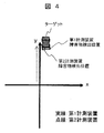
- FIG. 4 shows a measurement result when the first measurement device 11 and the second measurement device 12 are not displaced from the initial setting position.
- FIG. 4 is a conceptual diagram illustrating a problem that occurs when the position of the sensor is displaced. It can be seen that the obstacle position detected by the first measuring device 11 and the obstacle position detected by the second measuring device 12 overlap.
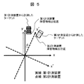
- FIG. 5 shows a case where the installation positions of the first measurement device 11 and the second measurement device 12 are deviated from the initial setting positions.
- FIG. 5 is a conceptual diagram illustrating a problem that occurs when the position of the sensor is displaced.
- the second measuring device 12 is shifted from the first measuring device 11 by an angle of ⁇ in the yaw direction.
- the sensor coordinate system of the second measuring device 12 is shifted from the sensor coordinate system of the first measuring device 11 by ⁇ in the yaw direction.
- the same target should be measured, but the positions of the obstacles are not overlapped as shown in FIG.
- the second obstacle detection unit 122 detects an obstacle based on information in the measurement area measured by the second measurement device 12 capable of detecting the position of the obstacle.
- the displacement determination permission unit 114 determines that there is an obstacle suitable for the obstacle displacement determination based on the information measured by the first measuring device 11, the same obstacle as the obstacle suitable for the determination is determined.
- the obstacle is detected from the obstacles detected by the second obstacle detector 122.
- the fact that the amount of displacement does not increase in the vicinity is used even when a displacement between sensors occurs.
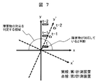
- FIGS. 6 and 7 are conceptual diagrams illustrating a method for determining whether or not an obstacle measured by the first measurement device and the second measurement device is the same.
- the misalignment determination unit 115 detects the first obstacle detection information accumulation unit 115a and the second obstacle detection unit 122 that accumulate time-series information of the obstacle detected by the first obstacle detection unit 112.
- a second obstacle detection information storage unit 115b for storing obstacle time-series information.
- the obstacle position detected by the first measurement device 11 and the detection by the second measurement device 12 are the same.
- the obstacle position is stored in the misalignment determination unit 115 as obstacle information of the same obstacle (FIG. 7). If it is determined from the information on the same obstacle detected by the first measurement device 11 and the second measurement device 12 stored in the displacement determination unit 115 that the displacement has occurred, the displacement determination unit reports the displacement. It reports to the unit 116 how much the installation position of the first measurement device 11 and the installation position of the second measurement device 12 are shifted.
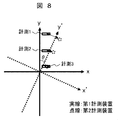
- FIG. 8 is a conceptual diagram illustrating an index for determining misalignment.
- a pair of information is designated as measurement 1, measurement 2, and measurement 3.
- the distance of the obstacle position of each pair at this time is measured.
- the maximum value of the distance exceeds a set threshold value, or when the cumulative value exceeds a set threshold value, it is determined that the first measurement device 11 and the second measurement device 12 are misaligned.
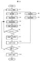
- FIG. 9 is a flowchart illustrating an operation procedure for determining a positional deviation between the second measurement device and the second measurement device.
- Steps 1 to 7 are the same as described in FIG.
- the second measuring device 12 measures the measurement area (step S8). Based on the information, the second obstacle detection unit 122 detects the presence and position of an obstacle (step S9). When the system receives a position deviation determination permission report in step S7, position deviation determination is performed (step S10). First, in the displacement determination unit 115, the first obstacle detection unit 112 detects in Step S3, and the second obstacle detection unit 122 detects an obstacle determined to be suitable for the displacement determination in Step S5. Search from obstacles. If there is a corresponding obstacle, a misalignment determination is performed (step S10). When it is determined that there is a positional shift, the process proceeds from step S11 to step S12. If there is no displacement, the process proceeds to step S1.
- step S10 the obstacle detected by the second obstacle detection unit 122 in step S10 is not the same obstacle as the obstacle determined to be suitable for the positional deviation determination in step S5
- the process proceeds to step S1.
- the position shift determination unit 115 determines that there is a position shift
- the position shift report unit 116 reports that the installation positions of the first measurement device 11 and the second measurement device 12 are shifted from the initial setting positions. To do.
- a presentation method at this time there are a method of presenting such information on the display 125, and a method of passing positional deviation information to another processing unit.
- the misalignment reporting unit 116 is provided separately from the calibration device (calibration unit) 130. However, the misalignment report unit 116 may be provided inside the calibration device 130.
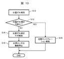
- FIG. 10 is a flowchart illustrating an operation procedure for determining whether or not calibration between sensors is performed.
- the inter-sensor calibration unit 117 can cope with the deviation by program parameter correction. It is determined whether or not. If it is determined that it can be handled, the calibration between the first measuring device 11 and the second measuring device 12 is performed, and how much parameter correction should be performed is calculated. When it is determined that the response is not possible, the functions of the first measurement device 11 and the second measurement device 12 are stopped, and the user is notified that a large displacement between the sensors has occurred.
- a pair of position information of the detected obstacle is defined as measurement 1, measurement 2, and measurement 3.
- the distance between obstacles in each pair at this time is measured.
- the maximum value of the distance exceeds a set threshold value, or when the cumulative value exceeds a set threshold value, it is determined that the first measurement device 11 and the second measurement device 12 are misaligned.
- a relative position parameter that minimizes the sum of squares of the distances between obstacles in each pair is searched.
- the parameter search method includes the steepest gradient method, the least square method, the Newton method, the Levenberg Marquardt method, and the like.
- step S12 the steps described in FIG. 9 are executed.
- step S13 When there is a report of the positional deviation between the first measuring device 11 and the second measuring device 12 in step S12, it is determined whether the positional deviation can be corrected (step S13). This determination is made based on the evaluation value calculated in step S10 in FIG. If the conditions set in advance are satisfied, it is determined that the parameter correction of the positional deviation is possible, and the process proceeds to step S16. If the condition cannot be satisfied, the process proceeds to step S14.
- step S14 the user is informed that the misalignment between the first measuring device 11 and the second measuring device 12 cannot be corrected (step S14).
- step S14 presentation by a buzzer sound or presentation on the display 125 can be considered.
- Step S15 the function of an external field sensor (the 1st measuring device 11, the 2nd measuring device 12) is stopped automatically (Step S15).
- step S16 automatic calibration is performed to determine the current relative position of the first measurement device 11 and the second measurement device 12. Based on the obtained relative position, the positional deviation generated in the first measuring device 11 and the second measuring device 12 is corrected.
- This correction is performed as follows in the case of FIG. In FIG. 7, it is determined at time t that the obstacle detected by the first measuring device 11 and the obstacle detected by the second measuring device 12 are the same obstacle. At this time t, a positional shift that has occurred in the first measuring device 11 and the second measuring device 12 from the relative position between the obstacle detected by the first measuring device 11 and the obstacle detected by the second measuring device 12. It is difficult to detect accurately.
- the positional deviation generated in the first measuring device 11 and the second measuring device 12 is detected by going back in time. For example, for obstacles determined as the same obstacle, the obstacles detected by the first measuring device 11 and the obstacles detected by the second measuring device 12 are traced back to the time t-1 or the time t-2. The relative positional relationship with the object is obtained by calculation.
- the retroactive time may be a time before time t-2.
- the difference between the position of the obstacle detected by the first measuring device 11 and the position of the obstacle detected by the second measuring device 12 usually increases as the time goes back. Then, based on the obtained relative positional relationship between the two obstacles, it is possible to accurately detect the positional deviation that has occurred in the first measuring device 11 and the second measuring device 12.
- the correction of the relative position change between the sensors caused by the secular change or the like can be automatically performed from the selection of the obstacle suitable for performing the calibration to the correction.
- the healthy state of the obstacle detection device can be maintained.
- a dump truck for mining travels off-road, it is not known when a positional shift between sensors occurs. Therefore, automatic calibration from obstacle selection to correction leads to an improvement in the operating rate of the vehicle.
- dump trucks for mines are often assembled locally (mine).
- the obstacle detection apparatus can be easily and accurately calibrated in the dump truck assembled on site.
- this invention is not limited to each above-mentioned Example, Various modifications are included.
- the above-described embodiments have been described in detail for easy understanding of the present invention, and are not necessarily limited to those having all the configurations.
- a part of the configuration of one embodiment can be replaced with the configuration of another embodiment, and the configuration of another embodiment can be added to the configuration of one embodiment.
- each of the above-described configurations, functions, processing units, processing means, and the like may be realized by hardware by designing a part or all of them with, for example, an integrated circuit.
- Each of the above-described configurations, functions, and the like may be realized by software by interpreting and executing a program that realizes each function by the processor.
- Information such as programs, tables, and files that realize each function can be stored in a memory, a hard disk, a recording device such as an SSD (Solid State Drive), or a recording medium such as an IC card, an SD card, or a DVD.
- control lines and information lines indicate what is considered necessary for the explanation, and not all the control lines and information lines on the product are necessarily shown. Actually, it may be considered that almost all the components are connected to each other.
- SYMBOLS 1 Vehicle (work machine for mines), 11 ... 1st measuring device, 12 ... 2nd measuring device, 112 ... 1st obstacle detection part, 113 ... Obstacle recognition part, 114 ... Misalignment determination permission part, 115 ... Misregistration determination unit 116 ... Misregistration report unit, 117 ... Inter-sensor calibration unit, 118 ... Obstacle database unit, 122 ... Second obstacle detection unit, 130 ... Calibration device, 131 ... Determination permission unit, 132 ... Determination unit, 200... Obstacle detection device.
Landscapes
- Engineering & Computer Science (AREA)
- Physics & Mathematics (AREA)
- Radar, Positioning & Navigation (AREA)
- Remote Sensing (AREA)
- General Physics & Mathematics (AREA)
- Computer Networks & Wireless Communication (AREA)
- General Engineering & Computer Science (AREA)
- Civil Engineering (AREA)
- Mining & Mineral Resources (AREA)
- Structural Engineering (AREA)
- Mechanical Engineering (AREA)
- Electromagnetism (AREA)
- Component Parts Of Construction Machinery (AREA)
- Traffic Control Systems (AREA)
- Radar Systems Or Details Thereof (AREA)
- Optical Radar Systems And Details Thereof (AREA)
Abstract
L'objet de la présente invention est de détecter et de corriger l'écart axial (écart de position) d'une pluralité de différents types de capteurs et de permettre une détection d'obstacle précise dans un cas où la détection d'obstacle est réalisée au moyen de la combinaison de la pluralité de capteurs. Un dispositif d'étalonnage selon la présente invention est pourvu : d'une unité de permission de détermination d'écart de position 114 permettant de déterminer, sur la base d'une forme géométrique mesurée par un premier dispositif de mesure 11, si un obstacle est approprié pour détecter l'écart de position entre le premier dispositif de mesure 11 et un second dispositif de mesure 12 ; et d'une unité d'étalonnage inter-capteur 117 permettant de détecter la quantité d'écart de position entre le premier dispositif de mesure 11 et le second dispositif de mesure 12 sur la base de la position détectée par le premier dispositif de mesure 11 pour un obstacle déterminé par l'unité de permission de détermination d'écart de position 114 comme étant approprié pour détecter l'écart de position et la position détectée par le second dispositif de mesure 12 de l'obstacle.
Applications Claiming Priority (2)
| Application Number | Priority Date | Filing Date | Title |
|---|---|---|---|
| JP2015111986A JP6523050B2 (ja) | 2015-06-02 | 2015-06-02 | 鉱山用作業機械 |
| JP2015-111986 | 2015-06-02 |
Publications (1)
| Publication Number | Publication Date |
|---|---|
| WO2016194426A1 true WO2016194426A1 (fr) | 2016-12-08 |
Family
ID=57440859
Family Applications (1)
| Application Number | Title | Priority Date | Filing Date |
|---|---|---|---|
| PCT/JP2016/056713 WO2016194426A1 (fr) | 2015-06-02 | 2016-03-04 | Engin de chantier pour mine |
Country Status (2)
| Country | Link |
|---|---|
| JP (1) | JP6523050B2 (fr) |
| WO (1) | WO2016194426A1 (fr) |
Cited By (3)
| Publication number | Priority date | Publication date | Assignee | Title |
|---|---|---|---|---|
| WO2019022173A1 (fr) * | 2017-07-26 | 2019-01-31 | 株式会社アドヴィックス | Appareil d'aide à l'arrêt d'un véhicule |
| CN110271502A (zh) * | 2018-03-16 | 2019-09-24 | 株式会社小糸制作所 | 传感器系统 |
| CN110497861A (zh) * | 2018-05-18 | 2019-11-26 | 株式会社小糸制作所 | 传感器系统及检查方法 |
Families Citing this family (4)
| Publication number | Priority date | Publication date | Assignee | Title |
|---|---|---|---|---|
| JP6684682B2 (ja) | 2016-08-18 | 2020-04-22 | 株式会社神戸製鋼所 | 建設機械 |
| JP7288895B2 (ja) * | 2018-03-05 | 2023-06-08 | 株式会社小糸製作所 | センサシステム、および画像データ生成装置 |
| JP7258613B2 (ja) * | 2019-03-18 | 2023-04-17 | 住友重機械工業株式会社 | 作業機械 |
| WO2020230619A1 (fr) | 2019-05-13 | 2020-11-19 | 日立オートモティブシステムズ株式会社 | Système de commande de véhicule |
Citations (3)
| Publication number | Priority date | Publication date | Assignee | Title |
|---|---|---|---|---|
| JP2010249613A (ja) * | 2009-04-14 | 2010-11-04 | Toyota Motor Corp | 障害物認識装置及び車両制御装置 |
| JP2011220732A (ja) * | 2010-04-06 | 2011-11-04 | Honda Motor Co Ltd | 車両の周辺監視装置 |
| WO2015005001A1 (fr) * | 2013-07-08 | 2015-01-15 | 本田技研工業株式会社 | Dispositif de reconnaissance d'objet |
Family Cites Families (2)
| Publication number | Priority date | Publication date | Assignee | Title |
|---|---|---|---|---|
| US7706978B2 (en) * | 2005-09-02 | 2010-04-27 | Delphi Technologies, Inc. | Method for estimating unknown parameters for a vehicle object detection system |
| US20070182623A1 (en) * | 2006-02-03 | 2007-08-09 | Shuqing Zeng | Method and apparatus for on-vehicle calibration and orientation of object-tracking systems |
-
2015
- 2015-06-02 JP JP2015111986A patent/JP6523050B2/ja active Active
-
2016
- 2016-03-04 WO PCT/JP2016/056713 patent/WO2016194426A1/fr active Application Filing
Patent Citations (3)
| Publication number | Priority date | Publication date | Assignee | Title |
|---|---|---|---|---|
| JP2010249613A (ja) * | 2009-04-14 | 2010-11-04 | Toyota Motor Corp | 障害物認識装置及び車両制御装置 |
| JP2011220732A (ja) * | 2010-04-06 | 2011-11-04 | Honda Motor Co Ltd | 車両の周辺監視装置 |
| WO2015005001A1 (fr) * | 2013-07-08 | 2015-01-15 | 本田技研工業株式会社 | Dispositif de reconnaissance d'objet |
Cited By (5)
| Publication number | Priority date | Publication date | Assignee | Title |
|---|---|---|---|---|
| WO2019022173A1 (fr) * | 2017-07-26 | 2019-01-31 | 株式会社アドヴィックス | Appareil d'aide à l'arrêt d'un véhicule |
| JP2019025977A (ja) * | 2017-07-26 | 2019-02-21 | 株式会社アドヴィックス | 車両の停止支援装置 |
| CN110271502A (zh) * | 2018-03-16 | 2019-09-24 | 株式会社小糸制作所 | 传感器系统 |
| CN110497861A (zh) * | 2018-05-18 | 2019-11-26 | 株式会社小糸制作所 | 传感器系统及检查方法 |
| CN110497861B (zh) * | 2018-05-18 | 2022-11-01 | 株式会社小糸制作所 | 传感器系统及检查方法 |
Also Published As
| Publication number | Publication date |
|---|---|
| JP6523050B2 (ja) | 2019-05-29 |
| JP2016223963A (ja) | 2016-12-28 |
Similar Documents
| Publication | Publication Date | Title |
|---|---|---|
| WO2016194426A1 (fr) | Engin de chantier pour mine | |
| EP2609396B1 (fr) | Système de navigation d'une machine avec contrôle d'intégrité | |
| AU2009213056B2 (en) | Machine sensor calibration system | |
| EP3074787B1 (fr) | Objet mobile autonome | |
| US9731728B2 (en) | Sensor abnormality detection device | |
| CN108139755B (zh) | 自己位置推定装置的异常检测装置以及车辆 | |
| US20210031795A1 (en) | Correcting a position of a vehicle with slam | |
| US20220169280A1 (en) | Method and Device for Multi-Sensor Data Fusion For Automated and Autonomous Vehicles | |
| AU2009213057A1 (en) | Machine sensor calibration system | |
| US20060276958A1 (en) | Inertial navigational guidance system for a driverless vehicle utilizing laser obstacle sensors | |
| CN104554272A (zh) | 存在目标车辆和周围物体时的避让转向操作的路径规划 | |
| JP6386412B2 (ja) | 運搬車両 | |
| WO2015098344A1 (fr) | Machine d'extraction minière | |
| CN111661047B (zh) | 车辆中的车道位置感测和跟踪 | |
| JP5392700B2 (ja) | 障害物検出装置、及び障害物検出方法 | |
| US9862383B2 (en) | Method for operating a vehicle based on one or more setpoint trajectories | |
| KR102126670B1 (ko) | 검출 영역을 최적화하는 장애물 추적 장치 및 방법 | |
| US11572064B2 (en) | Method for monitoring a surrounding area of a motor vehicle, sensor control unit, driver assistance system and motor vehicle | |
| CN108466623B (zh) | 用于检测车辆内的错误传感器安装以缓解与物体检测相关联的危险的系统和方法 | |
| US11756310B2 (en) | Method and device for sensor data fusion for a vehicle | |
| US10586407B2 (en) | Tire wear detection system for automated vehicle | |
| US20220281476A1 (en) | Aiming device, driving control system, and method for calculating correction amount for sensor data | |
| US11142187B2 (en) | Parking assistance device | |
| JP5860788B2 (ja) | 駐車空間検知装置 | |
| KR102253280B1 (ko) | 센서 퓨전 시스템 |
Legal Events
| Date | Code | Title | Description |
|---|---|---|---|
| 121 | Ep: the epo has been informed by wipo that ep was designated in this application |
Ref document number: 16802865 Country of ref document: EP Kind code of ref document: A1 |
|
| NENP | Non-entry into the national phase |
Ref country code: DE |
|
| 32PN | Ep: public notification in the ep bulletin as address of the adressee cannot be established |
Free format text: NOTING OF LOSS OF RIGHTS PURSUANT TO RULE 112(1) EPC (EPO FORM 1205A DATED 06.03.2018) |
|
| 122 | Ep: pct application non-entry in european phase |
Ref document number: 16802865 Country of ref document: EP Kind code of ref document: A1 |