WO2016194426A1 - Work machine for mine - Google Patents
Work machine for mine Download PDFInfo
- Publication number
- WO2016194426A1 WO2016194426A1 PCT/JP2016/056713 JP2016056713W WO2016194426A1 WO 2016194426 A1 WO2016194426 A1 WO 2016194426A1 JP 2016056713 W JP2016056713 W JP 2016056713W WO 2016194426 A1 WO2016194426 A1 WO 2016194426A1
- Authority
- WO
- WIPO (PCT)
- Prior art keywords
- obstacle
- measurement device
- unit
- information
- calibration
- Prior art date
Links
Images


Classifications
-
- B—PERFORMING OPERATIONS; TRANSPORTING
- B60—VEHICLES IN GENERAL
- B60R—VEHICLES, VEHICLE FITTINGS, OR VEHICLE PARTS, NOT OTHERWISE PROVIDED FOR
- B60R21/00—Arrangements or fittings on vehicles for protecting or preventing injuries to occupants or pedestrians in case of accidents or other traffic risks
-
- E—FIXED CONSTRUCTIONS
- E02—HYDRAULIC ENGINEERING; FOUNDATIONS; SOIL SHIFTING
- E02F—DREDGING; SOIL-SHIFTING
- E02F9/00—Component parts of dredgers or soil-shifting machines, not restricted to one of the kinds covered by groups E02F3/00 - E02F7/00
- E02F9/26—Indicating devices
-
- G—PHYSICS
- G01—MEASURING; TESTING
- G01S—RADIO DIRECTION-FINDING; RADIO NAVIGATION; DETERMINING DISTANCE OR VELOCITY BY USE OF RADIO WAVES; LOCATING OR PRESENCE-DETECTING BY USE OF THE REFLECTION OR RERADIATION OF RADIO WAVES; ANALOGOUS ARRANGEMENTS USING OTHER WAVES
- G01S13/00—Systems using the reflection or reradiation of radio waves, e.g. radar systems; Analogous systems using reflection or reradiation of waves whose nature or wavelength is irrelevant or unspecified
- G01S13/88—Radar or analogous systems specially adapted for specific applications
- G01S13/93—Radar or analogous systems specially adapted for specific applications for anti-collision purposes
-
- G—PHYSICS
- G01—MEASURING; TESTING
- G01S—RADIO DIRECTION-FINDING; RADIO NAVIGATION; DETERMINING DISTANCE OR VELOCITY BY USE OF RADIO WAVES; LOCATING OR PRESENCE-DETECTING BY USE OF THE REFLECTION OR RERADIATION OF RADIO WAVES; ANALOGOUS ARRANGEMENTS USING OTHER WAVES
- G01S7/00—Details of systems according to groups G01S13/00, G01S15/00, G01S17/00
- G01S7/02—Details of systems according to groups G01S13/00, G01S15/00, G01S17/00 of systems according to group G01S13/00
- G01S7/40—Means for monitoring or calibrating
-
- G—PHYSICS
- G08—SIGNALLING
- G08G—TRAFFIC CONTROL SYSTEMS
- G08G1/00—Traffic control systems for road vehicles
- G08G1/16—Anti-collision systems
Definitions
- the present invention relates to an obstacle detection device suitable for use in a mining work vehicle such as an off-road dump truck.
- mining work machines such as excavators and dump trucks are used for mining and transporting earth and sand.
- Mining work machines used in mines are required to be unmanned from the viewpoint of safety and cost reduction.
- dump trucks since the amount of earth and sand transported per unit time is directly linked to the progress of mining, efficient operation is required. Therefore, in order to efficiently transport a large amount of earth and sand outside the mining site, a mining system using an autonomously traveling dump truck capable of continuous operation is required.
- an obstacle detection device such as a millimeter wave radar, a laser sensor, a camera or a stereo camera
- the millimeter wave radar has a high environmental resistance capable of operating even when dust or rain occurs, and has a high measurement distance performance.
- a stereo camera or a laser sensor can measure a three-dimensional shape, an obstacle on the road can be detected with high accuracy.
- Patent Document 1 discloses an obstacle recognition device that corrects the axial misalignment between an in-vehicle camera and an in-vehicle radar caused by aging based on positional information of an obstacle detected by each sensor. It has been published.
- the obstacle recognition device of Patent Literature 1 is an obstacle recognition device that recognizes an obstacle by combining a plurality of sensor information, and the front camera that acquires first parameter information about the obstacle, Based on the millimeter wave radar that acquires the second parameter information about the obstacle, and the first parameter information and the second parameter information, the azimuth misalignment amount of the front camera or the millimeter wave radar is calculated, and the calculated misalignment A correction unit that corrects the axial deviation of the front camera or the millimeter wave radar based on the amount and a storage unit that stores the axial deviation amount are provided (see summary).
- the obstacle detection device of Patent Document 1 is intended for vehicles traveling on general roads.
- Millimeter-wave radar has low lateral position resolution due to the characteristics of the sensor, and the lateral position error tends to be large when detecting the center position of a large vehicle such as a mine dump truck or a specially shaped vehicle such as an excavator. There is.
- the axis misalignment between the camera and the millimeter wave radar is corrected by the above method based on the detection result having a large error, there is a possibility that the obstacle detection accuracy is worse than before the correction.
- the present invention has been made in view of the above problems.
- axial misalignment (position displacement) of the plurality of sensors is detected and corrected.
- the purpose is to enable easy obstacle detection.
- a calibration device of the present invention includes a first measurement device capable of measuring a geometric shape in a measurement region and a second measurement device capable of detecting the position of an obstacle.
- a calibration device that is provided in an obstacle detection device that detects an obstacle existing around a vehicle and corrects a positional deviation between the first measurement device and the second measurement device;
- An obstacle recognition unit capable of detecting at least one of the height, width, shape, image feature, or type of an obstacle present in the measurement area based on information measured by the first measurement device; , Position shift determination permission for determining whether the obstacle is an obstacle suitable for detecting a position shift between the first measurement device and the second measurement device based on information detected by the obstacle recognition unit.
- the correction of the relative position change between the sensors caused by the secular change or the like can be automatically performed from the selection of the obstacle suitable for performing the calibration to the correction. Thereby, the healthy state of the obstacle detection device can be maintained.
- FIG. 1 is a block diagram showing an outline of a configuration according to an embodiment of a calibration apparatus of the present invention.
- the vehicle 1 includes an obstacle detection device 200.
- the obstacle detection device 200 detects an obstacle present around the vehicle 1.
- the obstacle detection device 200 includes a first measurement device 11 and a second measurement device 12 in front of the vehicle body (front side) as a plurality of sensors.
- the first measuring device is a sensor capable of measuring the shape of an obstacle such as a monocular camera, a stereo camera, a LIDAR, or a TOF sensor. That is, the first measuring device 11 is a sensor capable of measuring a geometric shape in the measurement region.
- the second measuring device 12 is a sensor that can measure the position of an obstacle such as a millimeter wave sensor.
- the first measuring device 11 and the second measuring device 12 are attached to the front of the vehicle, but a part of the measurement area measured by the first measuring device 11 and the second measuring device 12, or If all are superposed, the present invention can be carried out regardless of the installation positions of the first measuring device 11 and the second measuring device 12.
- a mine dump truck used in a mine is described as the vehicle 1.
- the vehicle 1 may be a vehicle other than a mining dump truck used in a mine.
- Mining work trucks including mining dump trucks and vehicles other than mining dump trucks are called mining work machines.
- the calibration apparatus 130 of this invention is applicable also to vehicles other than the working machine for mines.
- the calibration device 130 is provided with a determination permission unit 131.
- the determination permission unit 131 includes a first obstacle detection unit 112, an obstacle recognition unit 113, and a positional deviation determination permission unit 114.
- the determination permission unit 131 configures an obstacle selection unit that selects a target obstacle for performing a positional deviation determination.
- a target obstacle an obstacle for performing misalignment determination or an object suitable for misalignment determination.
- the calibration device 130 is a device that corrects misalignment between the first measurement device 11 and the second measurement device 12, and in FIG. 1, the calibration device 130, the first measurement device 11, and the second measurement device 12. And are configured separately. However, the first measuring device 11 and the second measuring device 12 may be included in the calibration device 130.
- the first measurement device 11 performs measurement in the measurement region, and the first obstacle detection unit 112 detects the position of the obstacle based on the information. Further, the obstacle recognizing unit 113 recognizes the information on the obstacle measured by the first obstacle detecting unit 112 based on the information of the first measuring device 11 and the first obstacle detecting unit 112.
- the obstacle information recognized at this time is at least one of the height, width, shape, image feature, and type of the obstacle.
- FIG. 2 is a conceptual diagram showing dispersion of obstacle detection positions depending on the size of the target.
- FIG. 2 shows how the vehicle 1 measures a large target 21 and a small target 22.
- the target (large size) 21 exists in the measurement area 31.
- the position measured by the second measuring means is estimated to be some part of the target (large size) 21 existing in the measurement region.
- distribution tends to become large compared with the case where the target is a target (small) 22 such as a general passenger car.
- the displacement of the installation positions of the first measurement device 11 and the second measurement device 22 is determined based on the position information of the same obstacle detected by the first obstacle detection unit 112 and the second obstacle detection unit 122. Assumes that For this reason, it can be said that the target (small) 22 having a small dispersion of obstacle detection positions is more suitable for determining the displacement between the sensors than the target (large) 21 having a large dispersion of obstacle detection positions.
- the displacement determination permission unit 114 determines the displacement of the first measurement device 11 and the second measurement device 12 based on the height, width, shape, image feature, and type of the obstacle detected by the obstacle recognition unit 113. It is determined whether it is suitable to do. For example, the range of the height and width of the obstacle is set in advance, and if it is within the range, it is determined that the obstacle is suitable for the obstacle for determining the displacement.
- the information in the obstacle database unit 118 may be used to determine whether or not the object is suitable for an obstacle for determining positional deviation.
- the obstacle database unit 118 is configured by a storage device that registers in advance information on obstacles suitable for determining positional deviation between sensors.
- the obstacle database unit 118 may store the height and width ranges of the obstacle for determining the target obstacle.
- the misregistration determination permission unit 114 moves the obstacle between the sensors. It is determined that it is suitable for the determination of misalignment. That is, the positional deviation determination permission unit 114 selects the obstacle as a target obstacle.
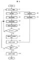
- FIG. 3 is a flowchart showing an operation procedure according to the embodiment of the calibration apparatus of the present invention.
- the power is turned on to the first measuring device 11 and the computer 13, and the measurement of the obstacle is started (step S1).
- the first measurement device 11 sends the shape information in the measurement area to the first obstacle detection unit 112 (step S2).
- the first obstacle detection unit 112 determines the position of the obstacle based on the shape information from the first measurement device 11 (step S3).
- the obstacle recognition unit 113 uses the height, width, and shape of the obstacle. Any one or more of image features and types is detected (step S4).
- the positional deviation determination permission unit 114 is the first when any one or more of the height, width, shape, image feature, and type of the obstacle detected by the obstacle recognition unit 113 satisfies a preset condition. It is determined that there is an obstacle (target obstacle) suitable for detecting the positional deviation between the measurement device 11 and the second measurement device 12, and the positional deviation determination is permitted (step S5). When the position deviation determination is permitted in step S5, the process proceeds to step 7 (step S6). If the position deviation determination is not permitted in step S5, the process returns to step S1 (step S6). In step S7, the presence / absence of the target obstacle and position information are presented to the system (step S7). As a presentation method at this time, there is a method of presenting such information on the display 125 (see FIG. 1), and a method of passing the presence / absence of an obstacle and position information suitable for detecting misalignment to another processing unit. .
- a determination unit 132 is provided in the calibration device 130 in order to detect a positional deviation between the first measurement device 11 and the second measurement device 12.
- the determination unit 132 includes a second obstacle detection unit 122 and a positional deviation determination unit 115.
- the calibration device 130 uses the second measurement device 12, the second obstacle detection unit 122, and the displacement determination unit 115 to detect a displacement between the first measurement device 11 and the second measurement device 12.
- the detected misregistration information is reported by the misregistration reporting unit 116.
- the determination permission unit 131, the determination unit 132, and an inter-sensor calibration unit 117 described later constitute a calibration device 130.
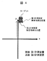
- FIG. 4 shows a measurement result when the first measurement device 11 and the second measurement device 12 are not displaced from the initial setting position.
- FIG. 4 is a conceptual diagram illustrating a problem that occurs when the position of the sensor is displaced. It can be seen that the obstacle position detected by the first measuring device 11 and the obstacle position detected by the second measuring device 12 overlap.
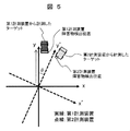
- FIG. 5 shows a case where the installation positions of the first measurement device 11 and the second measurement device 12 are deviated from the initial setting positions.
- FIG. 5 is a conceptual diagram illustrating a problem that occurs when the position of the sensor is displaced.
- the second measuring device 12 is shifted from the first measuring device 11 by an angle of ⁇ in the yaw direction.
- the sensor coordinate system of the second measuring device 12 is shifted from the sensor coordinate system of the first measuring device 11 by ⁇ in the yaw direction.
- the same target should be measured, but the positions of the obstacles are not overlapped as shown in FIG.
- the second obstacle detection unit 122 detects an obstacle based on information in the measurement area measured by the second measurement device 12 capable of detecting the position of the obstacle.
- the displacement determination permission unit 114 determines that there is an obstacle suitable for the obstacle displacement determination based on the information measured by the first measuring device 11, the same obstacle as the obstacle suitable for the determination is determined.
- the obstacle is detected from the obstacles detected by the second obstacle detector 122.
- the fact that the amount of displacement does not increase in the vicinity is used even when a displacement between sensors occurs.
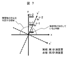
- FIGS. 6 and 7 are conceptual diagrams illustrating a method for determining whether or not an obstacle measured by the first measurement device and the second measurement device is the same.
- the misalignment determination unit 115 detects the first obstacle detection information accumulation unit 115a and the second obstacle detection unit 122 that accumulate time-series information of the obstacle detected by the first obstacle detection unit 112.
- a second obstacle detection information storage unit 115b for storing obstacle time-series information.
- the obstacle position detected by the first measurement device 11 and the detection by the second measurement device 12 are the same.
- the obstacle position is stored in the misalignment determination unit 115 as obstacle information of the same obstacle (FIG. 7). If it is determined from the information on the same obstacle detected by the first measurement device 11 and the second measurement device 12 stored in the displacement determination unit 115 that the displacement has occurred, the displacement determination unit reports the displacement. It reports to the unit 116 how much the installation position of the first measurement device 11 and the installation position of the second measurement device 12 are shifted.
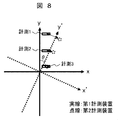
- FIG. 8 is a conceptual diagram illustrating an index for determining misalignment.
- a pair of information is designated as measurement 1, measurement 2, and measurement 3.
- the distance of the obstacle position of each pair at this time is measured.
- the maximum value of the distance exceeds a set threshold value, or when the cumulative value exceeds a set threshold value, it is determined that the first measurement device 11 and the second measurement device 12 are misaligned.
- FIG. 9 is a flowchart illustrating an operation procedure for determining a positional deviation between the second measurement device and the second measurement device.
- Steps 1 to 7 are the same as described in FIG.
- the second measuring device 12 measures the measurement area (step S8). Based on the information, the second obstacle detection unit 122 detects the presence and position of an obstacle (step S9). When the system receives a position deviation determination permission report in step S7, position deviation determination is performed (step S10). First, in the displacement determination unit 115, the first obstacle detection unit 112 detects in Step S3, and the second obstacle detection unit 122 detects an obstacle determined to be suitable for the displacement determination in Step S5. Search from obstacles. If there is a corresponding obstacle, a misalignment determination is performed (step S10). When it is determined that there is a positional shift, the process proceeds from step S11 to step S12. If there is no displacement, the process proceeds to step S1.
- step S10 the obstacle detected by the second obstacle detection unit 122 in step S10 is not the same obstacle as the obstacle determined to be suitable for the positional deviation determination in step S5
- the process proceeds to step S1.
- the position shift determination unit 115 determines that there is a position shift
- the position shift report unit 116 reports that the installation positions of the first measurement device 11 and the second measurement device 12 are shifted from the initial setting positions. To do.
- a presentation method at this time there are a method of presenting such information on the display 125, and a method of passing positional deviation information to another processing unit.
- the misalignment reporting unit 116 is provided separately from the calibration device (calibration unit) 130. However, the misalignment report unit 116 may be provided inside the calibration device 130.
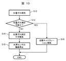
- FIG. 10 is a flowchart illustrating an operation procedure for determining whether or not calibration between sensors is performed.
- the inter-sensor calibration unit 117 can cope with the deviation by program parameter correction. It is determined whether or not. If it is determined that it can be handled, the calibration between the first measuring device 11 and the second measuring device 12 is performed, and how much parameter correction should be performed is calculated. When it is determined that the response is not possible, the functions of the first measurement device 11 and the second measurement device 12 are stopped, and the user is notified that a large displacement between the sensors has occurred.
- a pair of position information of the detected obstacle is defined as measurement 1, measurement 2, and measurement 3.
- the distance between obstacles in each pair at this time is measured.
- the maximum value of the distance exceeds a set threshold value, or when the cumulative value exceeds a set threshold value, it is determined that the first measurement device 11 and the second measurement device 12 are misaligned.
- a relative position parameter that minimizes the sum of squares of the distances between obstacles in each pair is searched.
- the parameter search method includes the steepest gradient method, the least square method, the Newton method, the Levenberg Marquardt method, and the like.
- step S12 the steps described in FIG. 9 are executed.
- step S13 When there is a report of the positional deviation between the first measuring device 11 and the second measuring device 12 in step S12, it is determined whether the positional deviation can be corrected (step S13). This determination is made based on the evaluation value calculated in step S10 in FIG. If the conditions set in advance are satisfied, it is determined that the parameter correction of the positional deviation is possible, and the process proceeds to step S16. If the condition cannot be satisfied, the process proceeds to step S14.
- step S14 the user is informed that the misalignment between the first measuring device 11 and the second measuring device 12 cannot be corrected (step S14).
- step S14 presentation by a buzzer sound or presentation on the display 125 can be considered.
- Step S15 the function of an external field sensor (the 1st measuring device 11, the 2nd measuring device 12) is stopped automatically (Step S15).
- step S16 automatic calibration is performed to determine the current relative position of the first measurement device 11 and the second measurement device 12. Based on the obtained relative position, the positional deviation generated in the first measuring device 11 and the second measuring device 12 is corrected.
- This correction is performed as follows in the case of FIG. In FIG. 7, it is determined at time t that the obstacle detected by the first measuring device 11 and the obstacle detected by the second measuring device 12 are the same obstacle. At this time t, a positional shift that has occurred in the first measuring device 11 and the second measuring device 12 from the relative position between the obstacle detected by the first measuring device 11 and the obstacle detected by the second measuring device 12. It is difficult to detect accurately.
- the positional deviation generated in the first measuring device 11 and the second measuring device 12 is detected by going back in time. For example, for obstacles determined as the same obstacle, the obstacles detected by the first measuring device 11 and the obstacles detected by the second measuring device 12 are traced back to the time t-1 or the time t-2. The relative positional relationship with the object is obtained by calculation.
- the retroactive time may be a time before time t-2.
- the difference between the position of the obstacle detected by the first measuring device 11 and the position of the obstacle detected by the second measuring device 12 usually increases as the time goes back. Then, based on the obtained relative positional relationship between the two obstacles, it is possible to accurately detect the positional deviation that has occurred in the first measuring device 11 and the second measuring device 12.
- the correction of the relative position change between the sensors caused by the secular change or the like can be automatically performed from the selection of the obstacle suitable for performing the calibration to the correction.
- the healthy state of the obstacle detection device can be maintained.
- a dump truck for mining travels off-road, it is not known when a positional shift between sensors occurs. Therefore, automatic calibration from obstacle selection to correction leads to an improvement in the operating rate of the vehicle.
- dump trucks for mines are often assembled locally (mine).
- the obstacle detection apparatus can be easily and accurately calibrated in the dump truck assembled on site.
- this invention is not limited to each above-mentioned Example, Various modifications are included.
- the above-described embodiments have been described in detail for easy understanding of the present invention, and are not necessarily limited to those having all the configurations.
- a part of the configuration of one embodiment can be replaced with the configuration of another embodiment, and the configuration of another embodiment can be added to the configuration of one embodiment.
- each of the above-described configurations, functions, processing units, processing means, and the like may be realized by hardware by designing a part or all of them with, for example, an integrated circuit.
- Each of the above-described configurations, functions, and the like may be realized by software by interpreting and executing a program that realizes each function by the processor.
- Information such as programs, tables, and files that realize each function can be stored in a memory, a hard disk, a recording device such as an SSD (Solid State Drive), or a recording medium such as an IC card, an SD card, or a DVD.
- control lines and information lines indicate what is considered necessary for the explanation, and not all the control lines and information lines on the product are necessarily shown. Actually, it may be considered that almost all the components are connected to each other.
- SYMBOLS 1 Vehicle (work machine for mines), 11 ... 1st measuring device, 12 ... 2nd measuring device, 112 ... 1st obstacle detection part, 113 ... Obstacle recognition part, 114 ... Misalignment determination permission part, 115 ... Misregistration determination unit 116 ... Misregistration report unit, 117 ... Inter-sensor calibration unit, 118 ... Obstacle database unit, 122 ... Second obstacle detection unit, 130 ... Calibration device, 131 ... Determination permission unit, 132 ... Determination unit, 200... Obstacle detection device.
Abstract
The purpose of the present invention is to detect and correct the axial deviation (positional deviation) of a plurality of different types of sensors and make accurate obstacle detection possible in a case where obstacle detection is carried out through the combination of the plurality of sensors. A calibration device according to the present invention is provided with: a positional deviation determination permission unit 114 for determining, on the basis of a geometric shape measured by a first measurement device 11, whether an obstacle is suitable for detecting the positional deviation between the first measurement device 11 and a second measurement device 12; and an intersensor calibration unit 117 for detecting the amount of positional deviation between the first measurement device 11 and the second measurement device 12 on the basis of the position detected by the first measurement device 11 for an obstacle determined by the positional deviation determination permission unit 114 to be suitable for detecting the positional deviation and the position detected by the second measurement device 12 for the obstacle.
Description
本発明は、例えばオフロードダンプトラック等の鉱山用作業車両用に用いるのに好適な障害物検出装置に関するものである.
The present invention relates to an obstacle detection device suitable for use in a mining work vehicle such as an off-road dump truck.
一般に、鉱山においては、土砂の採掘作業および運搬作業として油圧ショベルやダンプトラックなどの鉱山用作業機械が用いられている。鉱山に用いられる鉱山用作業機械としては、安全性や低コスト化の観点から無人化が求められる。ダンプトラックにおいては、単位時間当たりの土砂の運搬量が採掘の進捗度に直結するため、効率の良い運用が求められる。したがって、土砂を効率良く採掘現場の外に大量に運搬するためには、連続運転可能な自律走行式のダンプトラックを用いた鉱山システムが必要とされている。
Generally, in mines, mining work machines such as excavators and dump trucks are used for mining and transporting earth and sand. Mining work machines used in mines are required to be unmanned from the viewpoint of safety and cost reduction. In dump trucks, since the amount of earth and sand transported per unit time is directly linked to the progress of mining, efficient operation is required. Therefore, in order to efficiently transport a large amount of earth and sand outside the mining site, a mining system using an autonomously traveling dump truck capable of continuous operation is required.
ところが、ダンプトラックを走行させる鉱山の走行路はオフロードであって悪路が多いため、ダンプトラックを自律走行させて無人運転させる際、土壁や他車両等の障害物との衝突が懸念される。仮に、走行路上に障害物が生じ、自律走行式の無人のダンプトラックが障害物と接触して停止した場合には、鉱山の運行を長時間に亘って停止させてしまう。
よって、自律走行式のダンプトラックの信頼性を高めるためには、前方車両や走行路上の障害物を早期に検知して、前方車両に追従する追従走行や障害物の回避走行を行わせることが可能な信頼性の高い障害物検知システムが必要となる。 However, the mining roads that run dump trucks are off-road and there are many bad roads, so there are concerns about collisions with obstacles such as dirt walls and other vehicles when driving dump trucks autonomously and driving unattended. The If an obstacle occurs on the traveling road and an autonomous traveling unmanned dump truck comes into contact with the obstacle and stops, the operation of the mine is stopped for a long time.
Therefore, in order to improve the reliability of the autonomously traveling dump truck, it is possible to detect obstacles on the front vehicle and the road at an early stage, and to perform follow-up traveling following the preceding vehicle and avoiding obstacles. A reliable obstacle detection system is needed.
従来、この種の障害物検知システムとしては、ミリ波レーダ、レーザセンサ、カメラまたはステレオカメラ等の障害物検知装置が用いられている。ミリ波レーダは砂埃や雨などが生じた場合も動作可能な高い耐環境性を有し、測定距離性能も高い。一方で、ステレオカメラやレーザセンサは、三次元形状を計測できるため、路上の障害物を精度よく検出することができる。またこれらのセンサを組み合わせることで、障害物の検出性能を向上させる方法もある。
Conventionally, as this kind of obstacle detection system, an obstacle detection device such as a millimeter wave radar, a laser sensor, a camera or a stereo camera has been used. The millimeter wave radar has a high environmental resistance capable of operating even when dust or rain occurs, and has a high measurement distance performance. On the other hand, since a stereo camera or a laser sensor can measure a three-dimensional shape, an obstacle on the road can be detected with high accuracy. There is also a method of improving the obstacle detection performance by combining these sensors.
種類の異なる複数のセンサを用いるには各センサの相対位置を正確に把握する必要がある。特に鉱山ダンプに取り付ける場合は車体が大きいため、取り付け時のキャリブレーションの他、経年変化による位置ずれを考慮する必要がある。例えば特開2010-249613号公報(特許文献1)には、経年変化により生じた車載カメラと車載レーダの軸ずれをそれぞれのセンサが検出した障害物の位置情報に基づき補正する障害物認識装置が公開されている。具体的には、特許文献1の障害物認識装置は、複数のセンサ情報を組み合わせて障害物の認識を行う障害物認識装置であって、障害物に関する第一パラメータ情報を取得する前方カメラと、障害物に関する第二パラメータ情報を取得するミリ波レーダと、第一パラメータ情報と第二パラメータ情報とに基づいて前方カメラ又はミリ波レーダの方位角の軸ずれ量を算出し、算出された軸ずれ量に基づいて前方カメラ又はミリ波レーダの軸ずれを補正する補正部と、軸ずれ量を記憶する記憶部とを備えている(要約参照)。
To use multiple sensors of different types, it is necessary to accurately grasp the relative position of each sensor. In particular, when attaching to a mine dump truck, the vehicle body is large, so it is necessary to consider misalignment due to aging in addition to calibration at the time of attachment. For example, Japanese Patent Application Laid-Open No. 2010-249613 (Patent Document 1) discloses an obstacle recognition device that corrects the axial misalignment between an in-vehicle camera and an in-vehicle radar caused by aging based on positional information of an obstacle detected by each sensor. It has been published. Specifically, the obstacle recognition device of Patent Literature 1 is an obstacle recognition device that recognizes an obstacle by combining a plurality of sensor information, and the front camera that acquires first parameter information about the obstacle, Based on the millimeter wave radar that acquires the second parameter information about the obstacle, and the first parameter information and the second parameter information, the azimuth misalignment amount of the front camera or the millimeter wave radar is calculated, and the calculated misalignment A correction unit that corrects the axial deviation of the front camera or the millimeter wave radar based on the amount and a storage unit that stores the axial deviation amount are provided (see summary).
特許文献1の障害物検出装置は一般道を走行する車両を対象としたものである。ミリ波レーダはセンサの特性上横位置分解能が低く、鉱山ダンプのような大きな車両や、ショベルのような特殊な形状の車両の中心位置を検出する場合は横位置の誤差が大きくなりやすいという問題がある。誤差の大きい検出結果に基づき、上記の方法でカメラとミリ波レーダの軸ずれを補正した場合、補正前よりも障害物検出精度がかえって悪化する可能性がある。
The obstacle detection device of Patent Document 1 is intended for vehicles traveling on general roads. Millimeter-wave radar has low lateral position resolution due to the characteristics of the sensor, and the lateral position error tends to be large when detecting the center position of a large vehicle such as a mine dump truck or a specially shaped vehicle such as an excavator. There is. When the axis misalignment between the camera and the millimeter wave radar is corrected by the above method based on the detection result having a large error, there is a possibility that the obstacle detection accuracy is worse than before the correction.
本発明は、以上の課題に鑑みてなされたものであり、種類の異なる複数のセンサを組み合わせて障害物検出を行う場合において、複数のセンサの軸ずれ(位置ずれ)を検知、補正し、正確な障害物検出を可能にすることを目的とする。
The present invention has been made in view of the above problems. In the case where obstacle detection is performed by combining a plurality of different types of sensors, axial misalignment (position displacement) of the plurality of sensors is detected and corrected. The purpose is to enable easy obstacle detection.
上記目的を達成するために、本発明のキャリブレーション装置は、計測領域内の幾何学的形状を計測可能な第1計測装置と障害物の位置を検出可能な第2の計測装置とを有し、車両の周囲に存在する障害物を検出する障害物検出装置に設けられ、前記第1の計測装置及び前記第2計測装置の位置ずれを補正するキャリブレーション装置において、
前記第1計測装置の計測した情報に基づいて計測領域内に存在する障害物の高さ、横幅、形状、画像的特徴又は種類のうち少なくともいずれか一つの情報を検出可能な障害物認識部と、
前記障害物認識部で検出した情報に基づき、前記障害物が前記第1計測装置と前記第2計測装置との位置ずれを検出するのに適した障害物か否かを判定する位置ずれ判定許可部と、
前記位置ずれ判定許可部によって位置ずれを検出するのに適した障害物であると判定された障害物に対する前記第1計測装置による検出位置と、前記障害物に対する前記第2計測装置による検出位置とに基づいて、前記第1計測装置と前記第2計測装置との位置ずれ量を検出するセンサ間キャリブレーション部とを備える。 In order to achieve the above object, a calibration device of the present invention includes a first measurement device capable of measuring a geometric shape in a measurement region and a second measurement device capable of detecting the position of an obstacle. A calibration device that is provided in an obstacle detection device that detects an obstacle existing around a vehicle and corrects a positional deviation between the first measurement device and the second measurement device;
An obstacle recognition unit capable of detecting at least one of the height, width, shape, image feature, or type of an obstacle present in the measurement area based on information measured by the first measurement device; ,
Position shift determination permission for determining whether the obstacle is an obstacle suitable for detecting a position shift between the first measurement device and the second measurement device based on information detected by the obstacle recognition unit. And
A detection position by the first measurement device for an obstacle determined to be an obstacle suitable for detecting a displacement by the position deviation determination permission unit, and a detection position by the second measurement device for the obstacle; And a sensor-to-sensor calibration unit that detects the amount of positional deviation between the first measurement device and the second measurement device.
本発明に係るキャリブレーション装置においては、経年変化等により生じるセンサ間の相対位置変化の補正を、キャリブレーションを行うのに適した障害物の選定から補正まで自動で行うことができる。これにより障害物検出装置の健全な状態を維持することができる。
In the calibration apparatus according to the present invention, the correction of the relative position change between the sensors caused by the secular change or the like can be automatically performed from the selection of the obstacle suitable for performing the calibration to the correction. Thereby, the healthy state of the obstacle detection device can be maintained.
上記した以外の課題、構成及び効果は、以下の実施形態の説明により明らかにされる。
Issues, configurations, and effects other than those described above will be clarified by the following description of the embodiments.
図1は、本発明のキャリブレーション装置の実施例に係る構成の概要を示したブロック図である。
FIG. 1 is a block diagram showing an outline of a configuration according to an embodiment of a calibration apparatus of the present invention.
車両1は、障害物検出装置200を備える。障害物検出装置200は車両1の周囲に存在する障害物を検出する。障害物検出装置200は、複数のセンサとして、車体の前方(前側)に第1計測装置11と第2計測装置12とを備えている。第1計測装置は単眼カメラ、ステレオカメラ、LIDAR、TOFセンサなどの障害物の形状を計測可能なセンサとする。すなわち、第1計測装置11は計測領域内の幾何学的形状を計測可能なセンサである。第2計測装置12はミリ波センサのような障害物の位置を計測可能なセンサとする。なお、本実施例では、第1計測装置11と第2計測装置12とを車両の前方に取り付けているが、第1計測装置11と第2計測装置12が計測する計測領域の一部、あるいは全部が重畳していれば、第1計測装置11及び第2計測装置12の設置位置に関わらず本発明を実施することができる。
The vehicle 1 includes an obstacle detection device 200. The obstacle detection device 200 detects an obstacle present around the vehicle 1. The obstacle detection device 200 includes a first measurement device 11 and a second measurement device 12 in front of the vehicle body (front side) as a plurality of sensors. The first measuring device is a sensor capable of measuring the shape of an obstacle such as a monocular camera, a stereo camera, a LIDAR, or a TOF sensor. That is, the first measuring device 11 is a sensor capable of measuring a geometric shape in the measurement region. The second measuring device 12 is a sensor that can measure the position of an obstacle such as a millimeter wave sensor. In the present embodiment, the first measuring device 11 and the second measuring device 12 are attached to the front of the vehicle, but a part of the measurement area measured by the first measuring device 11 and the second measuring device 12, or If all are superposed, the present invention can be carried out regardless of the installation positions of the first measuring device 11 and the second measuring device 12.
本実施例では、車両1として、鉱山で使用される鉱山用ダンプトラックについて説明している。車両1は、鉱山で使用される、鉱山用ダンプトラック以外の車両であっても良い。鉱山用ダンプトラックと鉱山用ダンプトラック以外の車両とを含めて鉱山用作業機械という。また、本発明のキャリブレーション装置130は、鉱山用作業機械以外の車両にも適用可能である。
In this embodiment, a mine dump truck used in a mine is described as the vehicle 1. The vehicle 1 may be a vehicle other than a mining dump truck used in a mine. Mining work trucks including mining dump trucks and vehicles other than mining dump trucks are called mining work machines. Moreover, the calibration apparatus 130 of this invention is applicable also to vehicles other than the working machine for mines.
最初に、第1計測装置11を用いた位置ずれ判定の対象となる障害物の選定について説明する。
First, the selection of an obstacle to be subjected to the positional deviation determination using the first measuring device 11 will be described.
障害物の選定を行うために、キャリブレーション装置130には、判定許可部131が設けられている。判定許可部131は、第1障害物検出部112と、障害物認識部113と、位置ずれ判定許可部114とを有する。判定許可部131は、位置ずれ判定を行うための対象障害物を選定する障害物選定部を構成する。以下、位置ずれ判定を行うための障害物又は位置ずれ判定に向いている対象物を、対象障害物という。
In order to select an obstacle, the calibration device 130 is provided with a determination permission unit 131. The determination permission unit 131 includes a first obstacle detection unit 112, an obstacle recognition unit 113, and a positional deviation determination permission unit 114. The determination permission unit 131 configures an obstacle selection unit that selects a target obstacle for performing a positional deviation determination. Hereinafter, an obstacle for performing misalignment determination or an object suitable for misalignment determination is referred to as a target obstacle.
なお、キャリブレーション装置130は、第1計測装置11と第2計測装置12との位置ずれを補正する装置であり、図1では、キャリブレーション装置130と第1計測装置11及び第2計測装置12とを別々の構成にしている。しかし、第1計測装置11及び第2計測装置12をキャリブレーション装置130に含めても良い。
Note that the calibration device 130 is a device that corrects misalignment between the first measurement device 11 and the second measurement device 12, and in FIG. 1, the calibration device 130, the first measurement device 11, and the second measurement device 12. And are configured separately. However, the first measuring device 11 and the second measuring device 12 may be included in the calibration device 130.
第1計測装置11が計測領域内の計測を行い、その情報に基づき第1障害物検出部112が障害物の位置を検出する。さらに障害物認識部113は第1計測装置11及び第1障害物検出部112の情報に基づき第1障害物検出部112で計測した障害物の情報を認識する。このとき認識する障害物の情報は障害物の高さ、横幅、形状、画像特徴、種類のいずれかひとつ以上である。
The first measurement device 11 performs measurement in the measurement region, and the first obstacle detection unit 112 detects the position of the obstacle based on the information. Further, the obstacle recognizing unit 113 recognizes the information on the obstacle measured by the first obstacle detecting unit 112 based on the information of the first measuring device 11 and the first obstacle detecting unit 112. The obstacle information recognized at this time is at least one of the height, width, shape, image feature, and type of the obstacle.
図2は、ターゲットの大小による障害物検出位置の分散について示した概念図である。
図2は、車両1が大型のターゲット21と小型のターゲット22を計測している様子を示したものである。 FIG. 2 is a conceptual diagram showing dispersion of obstacle detection positions depending on the size of the target.
FIG. 2 shows how thevehicle 1 measures a large target 21 and a small target 22.
図2は、車両1が大型のターゲット21と小型のターゲット22を計測している様子を示したものである。 FIG. 2 is a conceptual diagram showing dispersion of obstacle detection positions depending on the size of the target.
FIG. 2 shows how the
計測領域31内にターゲット(大型)21が存在している。このとき第2計測手段が計測する位置は計測領域内に存在するターゲット(大型)21のどこか一部と推定される。このため、大型のターゲット21の場合には、ターゲットが一般乗用車のようなターゲット(小型)22の場合に比べ、その分散も大きくなる傾向にある。本実施例では、第1計測装置11と第2計測装置22の設置位置のずれを第1障害物検出部112と第2障害物検出部122の検出した同一障害物の位置情報に基づいて判定することを想定している。そのため、障害物の検出位置の分散が大きいターゲット(大型)21に比べ、障害物の検出位置の分散が小さいターゲット(小型)22のほうがセンサ間のずれを判定するのに適しているといえる。
The target (large size) 21 exists in the measurement area 31. At this time, the position measured by the second measuring means is estimated to be some part of the target (large size) 21 existing in the measurement region. For this reason, in the case of the large target 21, the dispersion | distribution tends to become large compared with the case where the target is a target (small) 22 such as a general passenger car. In this embodiment, the displacement of the installation positions of the first measurement device 11 and the second measurement device 22 is determined based on the position information of the same obstacle detected by the first obstacle detection unit 112 and the second obstacle detection unit 122. Assumes that For this reason, it can be said that the target (small) 22 having a small dispersion of obstacle detection positions is more suitable for determining the displacement between the sensors than the target (large) 21 having a large dispersion of obstacle detection positions.
位置ずれ判定許可部114は障害物認識部113が検出した障害物の高さ、横幅、形状、画像特徴、種類に基づき障害物が第1計測装置11と第2計測装置12の位置ずれを判定するのに適しているか否かを判定する。例えば事前に障害物の高さと横幅の範囲を設定し、その範囲内に収まっていればその障害物は位置ずれを判定する障害物に向いていると判定する。
The displacement determination permission unit 114 determines the displacement of the first measurement device 11 and the second measurement device 12 based on the height, width, shape, image feature, and type of the obstacle detected by the obstacle recognition unit 113. It is determined whether it is suitable to do. For example, the range of the height and width of the obstacle is set in advance, and if it is within the range, it is determined that the obstacle is suitable for the obstacle for determining the displacement.
もしくは障害物データベース部118の情報を利用して、位置ずれを判定する障害物に向いているか否かを判定しても良い。障害物データベース部118は事前にセンサ間の位置ずれ判定に適している障害物の情報を登録する記憶装置によって構成される。障害物データベース部118は、対象障害物を判定するための上記障害物の高さと横幅の範囲を記憶しても良い。
Alternatively, the information in the obstacle database unit 118 may be used to determine whether or not the object is suitable for an obstacle for determining positional deviation. The obstacle database unit 118 is configured by a storage device that registers in advance information on obstacles suitable for determining positional deviation between sensors. The obstacle database unit 118 may store the height and width ranges of the obstacle for determining the target obstacle.
検出した障害物の高さ、横幅、形状、画像特徴、種類のいずれかひとつ、あるいは複数の項目が一致したとき(条件を満たしたとき)、位置ずれ判定許可部114はその障害物をセンサ間の位置ずれ判定に適していると判断する。すなわち、位置ずれ判定許可部114はその障害物を対象障害物に選定する。
When any one of the detected obstacle's height, width, shape, image feature, type, or a plurality of items match (when the condition is met), the misregistration determination permission unit 114 moves the obstacle between the sensors. It is determined that it is suitable for the determination of misalignment. That is, the positional deviation determination permission unit 114 selects the obstacle as a target obstacle.
以下、図3のアルゴリズムフローを用いて説明する。図3は、本発明のキャリブレーション装置の実施例に係る動作手順を示すフローチャート図である。
Hereinafter, description will be made using the algorithm flow of FIG. FIG. 3 is a flowchart showing an operation procedure according to the embodiment of the calibration apparatus of the present invention.
第1計測装置11及び計算機13に電源が入り、障害物の計測を開始する(ステップS1)。第1計測装置11が計測領域内の形状情報を第1障害物検出部112に送る(ステップS2)。第1障害物検出部112は、第1計測装置11からの形状情報に基づいて障害物の位置を判定する(ステップS3)。次に第1計測装置11の計測した計測領域内の形状情報と第1障害物検出部112が検出した障害物の位置情報に基づき、障害物認識部113が障害物の高さ、横幅、形状、画像特徴、種類のいずれかひとつ以上を検出する(ステップS4)。位置ずれ判定許可部114は、障害物認識部113が検出した障害物の高さ、横幅、形状、画像特徴、種類のいずれかひとつ、あるいは複数が事前に設定した条件を満たした場合、第1計測装置11と第2計測装置12の位置ずれを検出するのに適した障害物(対象障害物)があったと判断し、位置ずれ判定を許可する(ステップS5)。ステップS5で位置ずれ判定を許可されていた場合、ステップ7に移行する(ステップS6)。ステップS5で位置ずれ判定を許可されていなかった場合、ステップS1に戻る(ステップS6)。ステップS7では、対象障害物の有無及び位置情報をシステムに提示する(ステップS7)。このときの提示方法としては、ディスプレイ125(図1参照)にこれらの情報を提示する方法、別の処理部に位置ずれを検出するのに適した障害物の有無と位置情報を渡す方法がある。
The power is turned on to the first measuring device 11 and the computer 13, and the measurement of the obstacle is started (step S1). The first measurement device 11 sends the shape information in the measurement area to the first obstacle detection unit 112 (step S2). The first obstacle detection unit 112 determines the position of the obstacle based on the shape information from the first measurement device 11 (step S3). Next, based on the shape information in the measurement region measured by the first measurement device 11 and the position information of the obstacle detected by the first obstacle detection unit 112, the obstacle recognition unit 113 uses the height, width, and shape of the obstacle. Any one or more of image features and types is detected (step S4). The positional deviation determination permission unit 114 is the first when any one or more of the height, width, shape, image feature, and type of the obstacle detected by the obstacle recognition unit 113 satisfies a preset condition. It is determined that there is an obstacle (target obstacle) suitable for detecting the positional deviation between the measurement device 11 and the second measurement device 12, and the positional deviation determination is permitted (step S5). When the position deviation determination is permitted in step S5, the process proceeds to step 7 (step S6). If the position deviation determination is not permitted in step S5, the process returns to step S1 (step S6). In step S7, the presence / absence of the target obstacle and position information are presented to the system (step S7). As a presentation method at this time, there is a method of presenting such information on the display 125 (see FIG. 1), and a method of passing the presence / absence of an obstacle and position information suitable for detecting misalignment to another processing unit. .
次に、図4~図9を用いて、第1計測装置11と第2計測装置12との間の位置ずれ検出方法について説明する。
Next, a method for detecting misalignment between the first measuring device 11 and the second measuring device 12 will be described with reference to FIGS.
図1に示すように、第1計測装置11と第2計測装置12との間の位置ずれを検出するために、キャリブレーション装置130には、判定部132が設けられている。判定部132は、第2障害物検出部122と、位置ずれ判定部115とを有する。キャリブレーション装置130は、第2計測装置12と第2障害物検出部122と位置ずれ判定部115とを用い、第1計測装置11と第2計測装置12との間の位置ずれを検出する。検出した位置ずれ情報は、位置ずれ報告部116により報告される。
As shown in FIG. 1, a determination unit 132 is provided in the calibration device 130 in order to detect a positional deviation between the first measurement device 11 and the second measurement device 12. The determination unit 132 includes a second obstacle detection unit 122 and a positional deviation determination unit 115. The calibration device 130 uses the second measurement device 12, the second obstacle detection unit 122, and the displacement determination unit 115 to detect a displacement between the first measurement device 11 and the second measurement device 12. The detected misregistration information is reported by the misregistration reporting unit 116.
なお、判定許可部131と判定部132と後述するセンサ間キャリブレーション部117とは、キャリブレーション装置130を構成する。
The determination permission unit 131, the determination unit 132, and an inter-sensor calibration unit 117 described later constitute a calibration device 130.
図4に第1計測装置11と第2計測装置12とが初期設定位置より位置ずれを起こしていない場合の計測結果を示す。図4は、センサ間の位置ずれ時に生じる問題について解説した概念図である。第1計測装置11が検出した障害物位置と第2計測装置12が検出した障害物位置とが重なっていることがわかる。
FIG. 4 shows a measurement result when the first measurement device 11 and the second measurement device 12 are not displaced from the initial setting position. FIG. 4 is a conceptual diagram illustrating a problem that occurs when the position of the sensor is displaced. It can be seen that the obstacle position detected by the first measuring device 11 and the obstacle position detected by the second measuring device 12 overlap.
次に、図5に第1計測装置11と第2計測装置12の設置位置が初期設定位置よりずれてしまった場合を示す。図5は、センサ間の位置ずれ時に生じる問題について解説した概念図である。この例では第2計測装置12が第1計測装置11に対し、ヨー方向に-θの角度だけずれてしまっている。このため、第2計測装置12のセンサ座標系は第1計測装置11のセンサ座標系に対しヨー方向にθだけずれている。その結果、同一のターゲットを計測しているはずが、センサ間の位置がずれてしまったことにより、図5のように障害物の検出位置が重なっていない。この場合、ひとつの障害物を複数個あるように誤認識する恐れがあるため、このセンサ間のずれの状態を検出する必要がある。
Next, FIG. 5 shows a case where the installation positions of the first measurement device 11 and the second measurement device 12 are deviated from the initial setting positions. FIG. 5 is a conceptual diagram illustrating a problem that occurs when the position of the sensor is displaced. In this example, the second measuring device 12 is shifted from the first measuring device 11 by an angle of −θ in the yaw direction. For this reason, the sensor coordinate system of the second measuring device 12 is shifted from the sensor coordinate system of the first measuring device 11 by θ in the yaw direction. As a result, the same target should be measured, but the positions of the obstacles are not overlapped as shown in FIG. In this case, since there is a possibility that one obstacle may be erroneously recognized as there are a plurality of obstacles, it is necessary to detect the state of deviation between the sensors.
図1に示すように、障害物の位置を検出可能な第2計測装置12が計測した計測領域内の情報に基づいて、第2障害物検出部122が障害物を検出する。第1計測装置11が計測した情報に基づいて位置ずれ判定許可部114が障害物の位置ずれ判定に適した障害物が存在すると判定した場合、その判定に適した障害物と同一の障害物を第2障害物検出部122で検出された障害物の中から探索する。同一障害物の探索方法については、センサ間のずれが生じた場合も、近方ではずれ量が大きくならないことを利用する。
As shown in FIG. 1, the second obstacle detection unit 122 detects an obstacle based on information in the measurement area measured by the second measurement device 12 capable of detecting the position of the obstacle. When the displacement determination permission unit 114 determines that there is an obstacle suitable for the obstacle displacement determination based on the information measured by the first measuring device 11, the same obstacle as the obstacle suitable for the determination is determined. The obstacle is detected from the obstacles detected by the second obstacle detector 122. As a search method for the same obstacle, the fact that the amount of displacement does not increase in the vicinity is used even when a displacement between sensors occurs.
同一障害物の探索方法について図6及び図7を用いて説明する。図6及び図7は、第1計測装置と第2計測装置とが計測した障害物に対して同一か否かを判定する方法について解説した概念図である。
The search method for the same obstacle will be described with reference to FIGS. 6 and 7 are conceptual diagrams illustrating a method for determining whether or not an obstacle measured by the first measurement device and the second measurement device is the same.
図6に示すように、時刻tのとき、事前に設定した障害物の対応を判定する領域内に障害物が存在し、第1計測装置11の検出した障害物位置と第2計測装置12の検出した障害物位置とが重なっている。このとき、この二つの障害物は同一障害物であると判定する。さらに、それ以降の時刻t+1,t+2,…,t+nでも、第1計測装置11と第2計測装置12とがそれぞれ障害物を追従できる限り、この障害物は同一障害物であるとみなし、それらの位置情報を位置ずれ判定部115に記憶する。
As shown in FIG. 6, at time t, there is an obstacle in the area for determining the correspondence of the obstacle set in advance, and the obstacle position detected by the first measuring device 11 and the second measuring device 12 The detected obstacle position overlaps. At this time, it is determined that the two obstacles are the same obstacle. Further, at the subsequent times t + 1, t + 2,..., T + n, as long as the first measuring device 11 and the second measuring device 12 can follow the obstacles, the obstacles are regarded as the same obstacle, The positional information is stored in the positional deviation determination unit 115.
このために、位置ずれ判定部115は、第1障害物検出部112の検出した障害物の時系列情報を蓄積する第1障害物検出情報蓄積部115aと第2障害物検出部122の検出した障害物の時系列情報を蓄積する第2障害物検出情報蓄積部115bとを有する。
For this purpose, the misalignment determination unit 115 detects the first obstacle detection information accumulation unit 115a and the second obstacle detection unit 122 that accumulate time-series information of the obstacle detected by the first obstacle detection unit 112. A second obstacle detection information storage unit 115b for storing obstacle time-series information.
一方でその同一障害物と判定する前の時刻t-1,1-2,…,t-nにおいても同様に、第1計測装置11の検出した障害物位置と第2計測装置12の検出した障害物位置とを同一障害物の障害物情報として位置ずれ判定部115に記憶する(図7)。位置ずれ判定部115に記憶された第1計測装置11と第2計測装置12とが検出した同一の障害物の情報から位置ずれが生じていると判断した場合、位置ずれ判定部は位置ずれ報告部116に第1計測装置11の設置位置と第2計測装置12の設置位置とがどの程度ずれているか報告する。
On the other hand, at the times t−1, 1-2,..., Tn before the determination that the obstacle is the same, the obstacle position detected by the first measurement device 11 and the detection by the second measurement device 12 are the same. The obstacle position is stored in the misalignment determination unit 115 as obstacle information of the same obstacle (FIG. 7). If it is determined from the information on the same obstacle detected by the first measurement device 11 and the second measurement device 12 stored in the displacement determination unit 115 that the displacement has occurred, the displacement determination unit reports the displacement. It reports to the unit 116 how much the installation position of the first measurement device 11 and the installation position of the second measurement device 12 are shifted.
図8を用いて、位置ずれを判定する方法について説明する。図8は、位置ずれ判定の指標について解説した概念図である。
A method for determining misalignment will be described with reference to FIG. FIG. 8 is a conceptual diagram illustrating an index for determining misalignment.
位置ずれを判定する方法としては、例えば図8のように第1障害物検出部112と第2障害物検出部122が検出した障害物のうち、同一でかつ同時刻に検出した障害物の位置情報のペアを計測1、計測2、計測3とする。このときの各ペアの障害物位置の距離を計測する.この距離の最大値が設定した閾値を超えた場合、もしくは累積値が設定した閾値を超えた場合、第1計測装置11と第2計測装置12は位置ずれを起こしていると判定する。
For example, as shown in FIG. 8, the position of the obstacle detected at the same time among the obstacles detected by the first obstacle detector 112 and the second obstacle detector 122 as shown in FIG. A pair of information is designated as measurement 1, measurement 2, and measurement 3. The distance of the obstacle position of each pair at this time is measured. When the maximum value of the distance exceeds a set threshold value, or when the cumulative value exceeds a set threshold value, it is determined that the first measurement device 11 and the second measurement device 12 are misaligned.
図9を用いて、位置ずれを判定するアルゴリズムフローについて説明する。図9は、第2計測装置と第2計測装置との位置ずれを判定する動作手順を示すフローチャート図である。
Referring to FIG. 9, the algorithm flow for determining misalignment will be described. FIG. 9 is a flowchart illustrating an operation procedure for determining a positional deviation between the second measurement device and the second measurement device.
ステップ1からステップ7までは図3で説明した内容と同様である。第2計測装置12が計測領域内を計測する(ステップS8)。その情報に基づき第2障害物検出部122で障害物の有無、位置を検出する(ステップS9)。ステップS7で位置ずれ判定許可報告をシステムが受けた場合、位置ずれ判定を実施する(ステップS10)。まず位置ずれ判定部115において、ステップS3で第1障害物検出部112が検出し、ステップS5において位置ずれ判定に適していると判定された障害物を、第2障害物検出部122が検出した障害物の中から探索する。対応する障害物があった場合、位置ずれ判定を実施する(ステップS10)。位置ずれがあると判定した場合、ステップS11からステップS12に移行する。位置ずれがなかった場合は、ステップS1に移行する。また、ステップS10にて、第2障害物検出部122が検出した障害物の中に、ステップS5において位置ずれ判定に適していると判定された障害物と同一の障害物がなかった場合も、ステップS1に移行する。位置ずれ判定部115が位置ずれ有りと判定した場合、位置ずれ報告部116(図1参照)は第1計測装置11と第2計測装置12の設置位置が初期設定位置よりずれていることを報告する。このときの提示方法としては、ディスプレイ125にこれらの情報を提示する方法、別の処理部に位置ずれ情報を渡す方法がある。
Steps 1 to 7 are the same as described in FIG. The second measuring device 12 measures the measurement area (step S8). Based on the information, the second obstacle detection unit 122 detects the presence and position of an obstacle (step S9). When the system receives a position deviation determination permission report in step S7, position deviation determination is performed (step S10). First, in the displacement determination unit 115, the first obstacle detection unit 112 detects in Step S3, and the second obstacle detection unit 122 detects an obstacle determined to be suitable for the displacement determination in Step S5. Search from obstacles. If there is a corresponding obstacle, a misalignment determination is performed (step S10). When it is determined that there is a positional shift, the process proceeds from step S11 to step S12. If there is no displacement, the process proceeds to step S1. Further, in the case where the obstacle detected by the second obstacle detection unit 122 in step S10 is not the same obstacle as the obstacle determined to be suitable for the positional deviation determination in step S5, The process proceeds to step S1. When the position shift determination unit 115 determines that there is a position shift, the position shift report unit 116 (see FIG. 1) reports that the installation positions of the first measurement device 11 and the second measurement device 12 are shifted from the initial setting positions. To do. As a presentation method at this time, there are a method of presenting such information on the display 125, and a method of passing positional deviation information to another processing unit.
なお、図1では、位置ずれ報告部116をキャリブレーション装置(キャリブレーション部)130とは別に設ける構成になっている。しかし、位置ずれ報告部116はキャリブレーション装置130の内部に設けられても良い。
In FIG. 1, the misalignment reporting unit 116 is provided separately from the calibration device (calibration unit) 130. However, the misalignment report unit 116 may be provided inside the calibration device 130.
次に、センサ間のキャリブレーションについて説明する。図10は、センサ間のキャリブレーションの実行の有無を判定する動作手順を示すフローチャート図である。
Next, calibration between sensors will be described. FIG. 10 is a flowchart illustrating an operation procedure for determining whether or not calibration between sensors is performed.
位置ずれ報告部116が第1計測装置11と第2計測装置12の設置位置が初期位置よりずれていると報告した場合、センサ間キャリブレーション部117はそのずれがプログラム上のパラメータ補正で対応可能か否かを判定する。対応可能であると判定した場合、第1計測装置11と第2計測装置12との間のキャリブレーションを実施し、どの程度パラメータ補正すればよいか演算する。対応不可であると判定した場合、第1計測装置11及び第2計測装置12の機能を停止し、大きなセンサ間の位置ずれが生じたことをユーザ側に報告する。
When the positional deviation reporting unit 116 reports that the installation positions of the first measuring device 11 and the second measuring device 12 are deviated from the initial positions, the inter-sensor calibration unit 117 can cope with the deviation by program parameter correction. It is determined whether or not. If it is determined that it can be handled, the calibration between the first measuring device 11 and the second measuring device 12 is performed, and how much parameter correction should be performed is calculated. When it is determined that the response is not possible, the functions of the first measurement device 11 and the second measurement device 12 are stopped, and the user is notified that a large displacement between the sensors has occurred.
パラメータ補正で対応可能か否かを判定する方法としては、例えば図8のように第1障害物検出部112と第2障害物検出部122が検出した障害物のうち、同一でかつ同時刻に検出した障害物の位置情報のペアを計測1、計測2、計測3とする。このときの各ペアにおける障害物間の距離を計測する。この距離の最大値が設定した閾値を超えた場合、もしくは累積値が設定した閾値を超えた場合、第1計測装置11と第2計測装置12は位置ずれを起こしていると判定する。
For example, as shown in FIG. 8, among the obstacles detected by the first obstacle detection unit 112 and the second obstacle detection unit 122 as shown in FIG. A pair of position information of the detected obstacle is defined as measurement 1, measurement 2, and measurement 3. The distance between obstacles in each pair at this time is measured. When the maximum value of the distance exceeds a set threshold value, or when the cumulative value exceeds a set threshold value, it is determined that the first measurement device 11 and the second measurement device 12 are misaligned.
またキャリブレーションにおいては、例えば各ペアにおける障害物間の距離の二乗和を最小化するような相対位置パラメータを探索する。探索した中でもっとも障害物間の距離の二乗和が小さかったものを新しいセンサ間位置と設定する方法がある。パラメータの探索方法としては最急勾配法、最小二乗法、ニュートン法、レーベンバーグマルカート法などがある。
In the calibration, for example, a relative position parameter that minimizes the sum of squares of the distances between obstacles in each pair is searched. There is a method of setting a new inter-sensor position that has the smallest sum of squares of distances between obstacles in the search. The parameter search method includes the steepest gradient method, the least square method, the Newton method, the Levenberg Marquardt method, and the like.
図10のアルゴリズムフローに基づき具体的に説明する。ステップS12以前には、図9で説明した内容のステップが実行される。
Specific description will be made based on the algorithm flow of FIG. Prior to step S12, the steps described in FIG. 9 are executed.
ステップS12にて第1計測装置11と第2計測装置12の位置ずれの報告が有った場合、その位置ずれが補正可能か判定する(ステップS13)。この判定は、図9のステップS10で算出した評価値を基に行う。事前に設定した条件を満たしていれば位置ずれのパラメータ補正が可能であるとして、ステップS16に移行する。条件を満たせない場合はステップS14に移行する。
When there is a report of the positional deviation between the first measuring device 11 and the second measuring device 12 in step S12, it is determined whether the positional deviation can be corrected (step S13). This determination is made based on the evaluation value calculated in step S10 in FIG. If the conditions set in advance are satisfied, it is determined that the parameter correction of the positional deviation is possible, and the process proceeds to step S16. If the condition cannot be satisfied, the process proceeds to step S14.
ステップS14に移行した場合、第1計測装置11と第2計測装置12の位置ずれが修正不可能であることをユーザ側に提示する(ステップS14)。提示方法としては、ブザー音による提示やディスプレイ125への提示が考えられる。その後、誤作動を防止するために、外界センサ(第1計測装置11、第2計測装置12)の機能を自動的に停止する(ステップS15)。
When the process proceeds to step S14, the user is informed that the misalignment between the first measuring device 11 and the second measuring device 12 cannot be corrected (step S14). As a presentation method, presentation by a buzzer sound or presentation on the display 125 can be considered. Then, in order to prevent malfunction, the function of an external field sensor (the 1st measuring device 11, the 2nd measuring device 12) is stopped automatically (Step S15).
ステップS16では自動キャリブレーションを実施し、現在の第1計測装置11と第2計測装置12の相対位置を求める。求めた相対位置に基づいて、第1計測装置11と第2計測装置12に生じた位置ずれを補正する。
In step S16, automatic calibration is performed to determine the current relative position of the first measurement device 11 and the second measurement device 12. Based on the obtained relative position, the positional deviation generated in the first measuring device 11 and the second measuring device 12 is corrected.
この補正は、図7の場合、以下のように実施される。図7では、第1計測装置11で検出された障害物と第2計測装置12で検出された障害物とが同一の障害物であることは、時刻tに判明する。この時刻tでは、第1計測装置11で検出された障害物と第2計測装置12で検出された障害物との相対位置から、第1計測装置11と第2計測装置12に生じた位置ずれを正確に検出することは難しい。
This correction is performed as follows in the case of FIG. In FIG. 7, it is determined at time t that the obstacle detected by the first measuring device 11 and the obstacle detected by the second measuring device 12 are the same obstacle. At this time t, a positional shift that has occurred in the first measuring device 11 and the second measuring device 12 from the relative position between the obstacle detected by the first measuring device 11 and the obstacle detected by the second measuring device 12. It is difficult to detect accurately.
そこで、時刻を遡って第1計測装置11と第2計測装置12に生じた位置ずれを検出する。例えば、同一の障害物と判定された障害物について、時刻t-1又は時刻t-2まで時刻を遡り、第1計測装置11で検出された障害物と第2計測装置12で検出された障害物との相対位置関係を演算により求める。
Therefore, the positional deviation generated in the first measuring device 11 and the second measuring device 12 is detected by going back in time. For example, for obstacles determined as the same obstacle, the obstacles detected by the first measuring device 11 and the obstacles detected by the second measuring device 12 are traced back to the time t-1 or the time t-2. The relative positional relationship with the object is obtained by calculation.
時刻t-1又は時刻t-2においては、第1計測装置11で検出された障害物の位置と第2計測装置12で検出された障害物の位置との間に大きな差が生じている。遡る時刻については、時刻t-2よりも前の時刻であっても良い。第1計測装置11で検出された障害物の位置と第2計測装置12で検出された障害物の位置との差は、通常、時間を遡るほど大きくなる。そして、求めた2つの障害物の相対位置関係に基づいて、第1計測装置11と第2計測装置12に生じた位置ずれを精度よく検出することができる。
At time t-1 or time t-2, there is a large difference between the position of the obstacle detected by the first measuring device 11 and the position of the obstacle detected by the second measuring device 12. The retroactive time may be a time before time t-2. The difference between the position of the obstacle detected by the first measuring device 11 and the position of the obstacle detected by the second measuring device 12 usually increases as the time goes back. Then, based on the obtained relative positional relationship between the two obstacles, it is possible to accurately detect the positional deviation that has occurred in the first measuring device 11 and the second measuring device 12.
あるいは、図6の場合には、現時点(時刻t)で同一の障害物を第1計測装置11と第2計測装置12とで検出していることが分かっている。そこで、将来の時刻t+1,t+2,…,t+nにおいて、第1計測装置11で検出される障害物の位置と第2計測装置12で検出される障害物の位置との間に差が生じた場合に、この差に基づいて、第1計測装置11と第2計測装置12に生じた位置ずれを検出するようにしてもよい。
Alternatively, in the case of FIG. 6, it is known that the same obstacle is detected by the first measuring device 11 and the second measuring device 12 at the present time (time t). Therefore, when a difference occurs between the position of the obstacle detected by the first measuring device 11 and the position of the obstacle detected by the second measuring device 12 at future times t + 1, t + 2,. In addition, based on this difference, a positional shift generated in the first measuring device 11 and the second measuring device 12 may be detected.
本実施例によれば、経年変化等により生じるセンサ間の相対位置変化の補正を、キャリブレーションを行うのに適した障害物の選定から補正まで自動で行うことができる。これにより障害物検出装置の健全な状態を維持することができる。特に、鉱山用のダンプトラックでは、オフロードを走行するため、いつセンサ間の位置ずれが生じるかわからない。
従って、障害物の選定から補正まで自動でキャリブレーションを行えることは、車両の稼働率の向上に繋がる。 According to the present embodiment, the correction of the relative position change between the sensors caused by the secular change or the like can be automatically performed from the selection of the obstacle suitable for performing the calibration to the correction. Thereby, the healthy state of the obstacle detection device can be maintained. In particular, since a dump truck for mining travels off-road, it is not known when a positional shift between sensors occurs.
Therefore, automatic calibration from obstacle selection to correction leads to an improvement in the operating rate of the vehicle.
また、鉱山用のダンプトラックでは、現地(鉱山)で組立てを行う場合が多い。本実施例を適用することにより、現地で組み立てたダンプトラックにおいて、障害物検出装置のキャリブレーションを簡単かつ正確に実施することができる。
Also, dump trucks for mines are often assembled locally (mine). By applying this embodiment, the obstacle detection apparatus can be easily and accurately calibrated in the dump truck assembled on site.
なお、本発明は上記した各実施例に限定されるものではなく、様々な変形例が含まれる。例えば、上記した実施例は本発明を分かりやすく説明するために詳細に説明したものであり、必ずしも全ての構成を備えるものに限定されるものではない。また、ある実施例の構成の一部を他の実施例の構成に置き換えることが可能であり、また、ある実施例の構成に他の実施例の構成を加えることも可能である。また、各実施例の構成の一部について、他の構成の追加・削除・置換をすることが可能である。
In addition, this invention is not limited to each above-mentioned Example, Various modifications are included. For example, the above-described embodiments have been described in detail for easy understanding of the present invention, and are not necessarily limited to those having all the configurations. Further, a part of the configuration of one embodiment can be replaced with the configuration of another embodiment, and the configuration of another embodiment can be added to the configuration of one embodiment. Further, it is possible to add, delete, and replace other configurations for a part of the configuration of each embodiment.
また、上記の各構成、機能、処理部、処理手段等は、それらの一部又は全部を、例えば集積回路で設計する等によりハードウェアで実現してもよい。また、上記の各構成、機能等は、プロセッサがそれぞれの機能を実現するプログラムを解釈し、実行することによりソフトウェアで実現してもよい。各機能を実現するプログラム、テーブル、ファイル等の情報は、メモリや、ハードディスク、SSD(Solid State Drive)等の記録装置、または、ICカード、SDカード、DVD等の記録媒体に置くことができる。
In addition, each of the above-described configurations, functions, processing units, processing means, and the like may be realized by hardware by designing a part or all of them with, for example, an integrated circuit. Each of the above-described configurations, functions, and the like may be realized by software by interpreting and executing a program that realizes each function by the processor. Information such as programs, tables, and files that realize each function can be stored in a memory, a hard disk, a recording device such as an SSD (Solid State Drive), or a recording medium such as an IC card, an SD card, or a DVD.
また、制御線や情報線は説明上必要と考えられるものを示しており、製品上必ずしも全ての制御線や情報線を示しているとは限らない。実際には殆ど全ての構成が相互に接続されていると考えてもよい。
Also, the control lines and information lines indicate what is considered necessary for the explanation, and not all the control lines and information lines on the product are necessarily shown. Actually, it may be considered that almost all the components are connected to each other.
1…車両(鉱山用作業機械)、11…第1計測装置、12…第2計測装置、112…第1障害物検出部、113…障害物認識部、114…位置ずれ判定許可部、115…位置ずれ判定部、116…位置ずれ報告部、117…センサ間キャリブレーション部、118…障害物データベース部、122…第2障害物検出部、130…キャリブレーション装置、131…判定許可部、132…判定部、200…障害物検出装置。
DESCRIPTION OF SYMBOLS 1 ... Vehicle (work machine for mines), 11 ... 1st measuring device, 12 ... 2nd measuring device, 112 ... 1st obstacle detection part, 113 ... Obstacle recognition part, 114 ... Misalignment determination permission part, 115 ... Misregistration determination unit 116 ... Misregistration report unit, 117 ... Inter-sensor calibration unit, 118 ... Obstacle database unit, 122 ... Second obstacle detection unit, 130 ... Calibration device, 131 ... Determination permission unit, 132 ... Determination unit, 200... Obstacle detection device.
Claims (8)
- 計測領域内の幾何学的形状を計測可能な第1計測装置と障害物の位置を検出可能な第2の計測装置とを有し、車両の周囲に存在する障害物を検出する障害物検出装置に設けられ、前記第1の計測装置及び前記第2計測装置の位置ずれを補正するキャリブレーション装置において、
前記第1計測装置の計測した情報に基づいて計測領域内に存在する障害物の高さ、横幅、形状、画像的特徴又は種類のうち少なくともいずれか一つの情報を検出可能な障害物認識部と、
前記障害物認識部で検出した情報に基づき、前記障害物が前記第1計測装置と前記第2計測装置との位置ずれを検出するのに適した障害物か否かを判定する位置ずれ判定許可部と、
前記位置ずれ判定許可部によって位置ずれを検出するのに適した障害物であると判定された障害物に対する前記第1計測装置による検出位置と、前記障害物に対する前記第2計測装置による検出位置とに基づいて、前記第1計測装置と前記第2計測装置との位置ずれ量を検出するセンサ間キャリブレーション部とを備えたことを特徴とするキャリブレーション装置。 Obstacle detection device for detecting an obstacle existing around a vehicle, having a first measurement device capable of measuring a geometric shape in a measurement region and a second measurement device capable of detecting the position of the obstacle Provided in the calibration device for correcting the positional deviation of the first measurement device and the second measurement device,
An obstacle recognition unit capable of detecting at least one of the height, width, shape, image feature, or type of an obstacle present in the measurement area based on information measured by the first measurement device; ,
Position shift determination permission for determining whether the obstacle is an obstacle suitable for detecting a position shift between the first measurement device and the second measurement device based on information detected by the obstacle recognition unit. And
A detection position by the first measurement device for an obstacle determined to be an obstacle suitable for detecting a displacement by the position deviation determination permission unit, and a detection position by the second measurement device for the obstacle; A calibration apparatus comprising: an inter-sensor calibration unit that detects a positional deviation amount between the first measurement apparatus and the second measurement apparatus based on the above. - 請求項1に記載のキャリブレーション装置において、
前記位置ずれ判定許可部は、障害物の高さ及び横幅が事前に設定した閾値の範囲内にあった場合に、前記障害物が前記第1計測装置と前記第2計測装置との位置ずれを判定するのに適した障害物であると判定することを特徴とするキャリブレーション装置。 The calibration device according to claim 1,
The misalignment determination permitting unit detects misalignment between the first measurement device and the second measurement device when the height and width of the obstacle are within a predetermined threshold range. A calibration apparatus characterized by determining an obstacle suitable for determination. - 請求項1に記載のキャリブレーション装置において、
前記位置ずれ判定許可部における位置ずれ判定に適した障害物の情報として、障害物の高さ、横幅、形状、画像的特徴又は種類のいずれかの情報を保持する障害物データベース部を有し、
前記位置ずれ判定許可部は、前記第1計測装置が計測した障害物が前記障害物データベース部に保持された障害物の高さ、横幅、形状、画像的特徴又は種類のいずれかにおいて一致したと判定した場合に、前記障害物が前記第1計測装置と前記第2計測装置との位置ずれを判定するのに適した障害物であると判定することを特徴とするキャリブレーション装置。 The calibration device according to claim 1,
As an obstacle information suitable for misalignment determination in the misalignment determination permission unit, it has an obstacle database unit that holds any information of height, width, shape, image characteristic or type of an obstacle,
The positional deviation determination permitting unit matches the obstacle measured by the first measuring device in any of the height, width, shape, image feature, or type of the obstacle held in the obstacle database unit. A calibration apparatus, wherein when determined, the obstacle is determined to be an obstacle suitable for determining a positional deviation between the first measurement device and the second measurement device. - 請求項1に記載のキャリブレーション装置において、
前記第1計測装置の計測した情報に基づいて計測領域内の障害物の位置を計測する第1障害物検出部と、
前記第2計測装置の計測した情報に基づいて計測領域内の障害物の位置を計測する第2障害物検出部と、
前記位置ずれ判定許可部が障害物を前記第1計測装置と前記第2計測装置との位置ずれを判定するのに適した障害物であると判定した場合に、前記第1障害物検出部が検出した前記障害物の位置情報と前記第2障害物検出部が検出した前記障害物の位置情報とに基づいて、前記第1計測装置と前記第2計測装置の設置位置にずれが生じているかを判定する位置ずれ判定部と、
前記第1計測装置と前記第2計測装置との設置位置のずれの有無を報告する位置ずれ報告部とを有することを特徴とするキャリブレーション装置。 The calibration device according to claim 1,
A first obstacle detection unit that measures the position of an obstacle in a measurement region based on information measured by the first measurement device;
A second obstacle detection unit that measures the position of the obstacle in the measurement region based on the information measured by the second measurement device;
When the displacement determination permission unit determines that the obstacle is an obstacle suitable for determining displacement between the first measurement device and the second measurement device, the first obstacle detection unit Whether there is a deviation in the installation positions of the first measurement device and the second measurement device based on the detected location information of the obstacle and the location information of the obstacle detected by the second obstacle detection unit. A position deviation determination unit for determining
A calibration apparatus, comprising: a positional deviation report unit that reports the presence / absence of a deviation in installation position between the first measurement apparatus and the second measurement apparatus. - 請求項4に記載のキャリブレーション装置において、
センサ間キャリブレーション部は、前記位置ずれ報告部が前記第1計測装置と前記第2計測装置との設置位置にずれが生じていると報告した場合に、前記第1障害物検出部の検出した前記障害物の障害物情報と前記第2障害物検出部の検出した前記障害物の障害物情報とに基づいて前記第1計測装置と前記第2計測装置との位置ずれを補正することを特徴とするキャリブレーション装置。 The calibration device according to claim 4,
The inter-sensor calibration unit detects the first obstacle detection unit when the positional deviation report unit reports that the installation position of the first measurement device and the second measurement device is shifted. A positional deviation between the first measurement device and the second measurement device is corrected based on the obstacle information of the obstacle and the obstacle information of the obstacle detected by the second obstacle detection unit. A calibration device. - 請求項4に記載のキャリブレーション装置において、
前記位置ずれ判定部は、前記第1障害物検出部の検出した障害物の時系列情報を蓄積する第1障害物検出情報蓄積部と前記第2障害物検出部の検出した障害物の時系列情報を蓄積する第2障害物検出情報蓄積部とを有し、
前記位置ずれ判定部は、前記第1障害物検出部が検出した障害物位置と前記第2障害物検出部が検出した障害物位置とが同じ時間帯に事前に設定した距離以内に接近した場合に、前記第1障害物検出部が検出した障害物と前記第2障害物検出部が検出した障害物とが同一の障害物であると判定し、前記第1計測装置が検出した前記障害物の位置情報と前記第2計測装置が検出した前記障害物の位置情報とに基づいて前記第1計測装置と前記第2計測装置との位置ずれ量を検出することを特徴とするキャリブレーション装置。 The calibration device according to claim 4,
The displacement determination unit includes a first obstacle detection information accumulation unit that accumulates time series information of obstacles detected by the first obstacle detection unit and a time series of obstacles detected by the second obstacle detection unit. A second obstacle detection information storage unit for storing information;
The displacement determination unit is configured such that the obstacle position detected by the first obstacle detection unit and the obstacle position detected by the second obstacle detection unit approach within a preset distance in the same time zone. The obstacle detected by the first obstacle detection unit and the obstacle detected by the second obstacle detection unit are determined to be the same obstacle, and the obstacle detected by the first measurement device A calibration device that detects a displacement amount between the first measurement device and the second measurement device based on the position information of the obstacle and the position information of the obstacle detected by the second measurement device. - 請求項6に記載のキャリブレーション装置において、
前記位置ずれ判定部は、前記第1障害物検出部が検出した障害物と前記第2障害物検出部が検出した障害物とが同一であるか否かの判定を、位置ずれ量を検出する時点から遡った時点で前記第1障害物検出情報蓄積部及び第2障害物検出情報蓄積部に蓄積された前記障害物の情報に基づいて行うことを特徴とするキャリブレーション装置。 The calibration device according to claim 6,
The misregistration determination unit detects a misregistration amount by determining whether the obstacle detected by the first obstacle detection unit and the obstacle detected by the second obstacle detection unit are the same. A calibration apparatus characterized in that the calibration is performed based on information on the obstacle accumulated in the first obstacle detection information accumulation unit and the second obstacle detection information accumulation unit at a time point retroactive from the time point. - 鉱山内を走行する鉱山用作業機械において、
請求項1に記載のキャリブレーション装置を備えたことを特徴とする鉱山用作業機械。 In a mining work machine that runs in a mine,
A mine work machine comprising the calibration device according to claim 1.
Applications Claiming Priority (2)
| Application Number | Priority Date | Filing Date | Title |
|---|---|---|---|
| JP2015111986A JP6523050B2 (en) | 2015-06-02 | 2015-06-02 | Mining work machine |
| JP2015-111986 | 2015-06-02 |
Publications (1)
| Publication Number | Publication Date |
|---|---|
| WO2016194426A1 true WO2016194426A1 (en) | 2016-12-08 |
Family
ID=57440859
Family Applications (1)
| Application Number | Title | Priority Date | Filing Date |
|---|---|---|---|
| PCT/JP2016/056713 WO2016194426A1 (en) | 2015-06-02 | 2016-03-04 | Work machine for mine |
Country Status (2)
| Country | Link |
|---|---|
| JP (1) | JP6523050B2 (en) |
| WO (1) | WO2016194426A1 (en) |
Cited By (3)
| Publication number | Priority date | Publication date | Assignee | Title |
|---|---|---|---|---|
| WO2019022173A1 (en) * | 2017-07-26 | 2019-01-31 | 株式会社アドヴィックス | Vehicle stoppage assistance apparatus |
| CN110271502A (en) * | 2018-03-16 | 2019-09-24 | 株式会社小糸制作所 | Sensing system |
| CN110497861A (en) * | 2018-05-18 | 2019-11-26 | 株式会社小糸制作所 | Sensing system and inspection method |
Families Citing this family (4)
| Publication number | Priority date | Publication date | Assignee | Title |
|---|---|---|---|---|
| JP6684682B2 (en) | 2016-08-18 | 2020-04-22 | 株式会社神戸製鋼所 | Construction machinery |
| JP7288895B2 (en) * | 2018-03-05 | 2023-06-08 | 株式会社小糸製作所 | Sensor system and image data generator |
| JP7258613B2 (en) * | 2019-03-18 | 2023-04-17 | 住友重機械工業株式会社 | working machine |
| DE112020001776T5 (en) | 2019-05-13 | 2022-01-27 | Hitachi Astemo, Ltd. | VEHICLE CONTROL SYSTEM |
Citations (3)
| Publication number | Priority date | Publication date | Assignee | Title |
|---|---|---|---|---|
| JP2010249613A (en) * | 2009-04-14 | 2010-11-04 | Toyota Motor Corp | Obstacle recognition device and vehicle control unit |
| JP2011220732A (en) * | 2010-04-06 | 2011-11-04 | Honda Motor Co Ltd | Vehicle surroundings monitoring device |
| WO2015005001A1 (en) * | 2013-07-08 | 2015-01-15 | 本田技研工業株式会社 | Object recognition device |
Family Cites Families (2)
| Publication number | Priority date | Publication date | Assignee | Title |
|---|---|---|---|---|
| US7706978B2 (en) * | 2005-09-02 | 2010-04-27 | Delphi Technologies, Inc. | Method for estimating unknown parameters for a vehicle object detection system |
| US20070182623A1 (en) * | 2006-02-03 | 2007-08-09 | Shuqing Zeng | Method and apparatus for on-vehicle calibration and orientation of object-tracking systems |
-
2015
- 2015-06-02 JP JP2015111986A patent/JP6523050B2/en active Active
-
2016
- 2016-03-04 WO PCT/JP2016/056713 patent/WO2016194426A1/en active Application Filing
Patent Citations (3)
| Publication number | Priority date | Publication date | Assignee | Title |
|---|---|---|---|---|
| JP2010249613A (en) * | 2009-04-14 | 2010-11-04 | Toyota Motor Corp | Obstacle recognition device and vehicle control unit |
| JP2011220732A (en) * | 2010-04-06 | 2011-11-04 | Honda Motor Co Ltd | Vehicle surroundings monitoring device |
| WO2015005001A1 (en) * | 2013-07-08 | 2015-01-15 | 本田技研工業株式会社 | Object recognition device |
Cited By (5)
| Publication number | Priority date | Publication date | Assignee | Title |
|---|---|---|---|---|
| WO2019022173A1 (en) * | 2017-07-26 | 2019-01-31 | 株式会社アドヴィックス | Vehicle stoppage assistance apparatus |
| JP2019025977A (en) * | 2017-07-26 | 2019-02-21 | 株式会社アドヴィックス | Vehicular stop support device |
| CN110271502A (en) * | 2018-03-16 | 2019-09-24 | 株式会社小糸制作所 | Sensing system |
| CN110497861A (en) * | 2018-05-18 | 2019-11-26 | 株式会社小糸制作所 | Sensing system and inspection method |
| CN110497861B (en) * | 2018-05-18 | 2022-11-01 | 株式会社小糸制作所 | Sensor system and inspection method |
Also Published As
| Publication number | Publication date |
|---|---|
| JP6523050B2 (en) | 2019-05-29 |
| JP2016223963A (en) | 2016-12-28 |
Similar Documents
| Publication | Publication Date | Title |
|---|---|---|
| WO2016194426A1 (en) | Work machine for mine | |
| EP2609396B1 (en) | Machine navigation system having integrity checking | |
| AU2009213056B2 (en) | Machine sensor calibration system | |
| EP3074787B1 (en) | Autonomous moving object | |
| US9731728B2 (en) | Sensor abnormality detection device | |
| CN108139755B (en) | Abnormality detection device for self-position estimation device, and vehicle | |
| US20210031795A1 (en) | Correcting a position of a vehicle with slam | |
| AU2009213057A1 (en) | Machine sensor calibration system | |
| US20060276958A1 (en) | Inertial navigational guidance system for a driverless vehicle utilizing laser obstacle sensors | |
| CN104554272A (en) | Path planning for evasive steering maneuver in presence of target vehicle and surrounding objects | |
| US20220169280A1 (en) | Method and Device for Multi-Sensor Data Fusion For Automated and Autonomous Vehicles | |
| JP6386412B2 (en) | Transport vehicle | |
| WO2015098344A1 (en) | Mining work machine | |
| CN111661047B (en) | Lane position sensing and tracking in a vehicle | |
| JP5392700B2 (en) | Obstacle detection device and obstacle detection method | |
| US9862383B2 (en) | Method for operating a vehicle based on one or more setpoint trajectories | |
| KR102126670B1 (en) | Apparatus and method for tracking objects with optimizing region of interest | |
| US11572064B2 (en) | Method for monitoring a surrounding area of a motor vehicle, sensor control unit, driver assistance system and motor vehicle | |
| US11756310B2 (en) | Method and device for sensor data fusion for a vehicle | |
| US10586407B2 (en) | Tire wear detection system for automated vehicle | |
| US20220281476A1 (en) | Aiming device, driving control system, and method for calculating correction amount for sensor data | |
| US11142187B2 (en) | Parking assistance device | |
| KR101197865B1 (en) | Method and apparatus for recognizing parking space | |
| KR102253280B1 (en) | Sensor fusion system | |
| JP2014071569A (en) | Parking space detection device |
Legal Events
| Date | Code | Title | Description |
|---|---|---|---|
| 121 | Ep: the epo has been informed by wipo that ep was designated in this application |
Ref document number: 16802865 Country of ref document: EP Kind code of ref document: A1 |
|
| NENP | Non-entry into the national phase |
Ref country code: DE |
|
| 32PN | Ep: public notification in the ep bulletin as address of the adressee cannot be established |
Free format text: NOTING OF LOSS OF RIGHTS PURSUANT TO RULE 112(1) EPC (EPO FORM 1205A DATED 06.03.2018) |
|
| 122 | Ep: pct application non-entry in european phase |
Ref document number: 16802865 Country of ref document: EP Kind code of ref document: A1 |