WO2016190330A1 - 複合焼結体切削工具 - Google Patents
複合焼結体切削工具 Download PDFInfo
- Publication number
- WO2016190330A1 WO2016190330A1 PCT/JP2016/065394 JP2016065394W WO2016190330A1 WO 2016190330 A1 WO2016190330 A1 WO 2016190330A1 JP 2016065394 W JP2016065394 W JP 2016065394W WO 2016190330 A1 WO2016190330 A1 WO 2016190330A1
- Authority
- WO
- WIPO (PCT)
- Prior art keywords
- ticn
- cemented carbide
- layer
- mass
- cermet
- Prior art date
- Legal status (The legal status is an assumption and is not a legal conclusion. Google has not performed a legal analysis and makes no representation as to the accuracy of the status listed.)
- Ceased
Links
Images


Classifications
-
- B—PERFORMING OPERATIONS; TRANSPORTING
- B22—CASTING; POWDER METALLURGY
- B22F—WORKING METALLIC POWDER; MANUFACTURE OF ARTICLES FROM METALLIC POWDER; MAKING METALLIC POWDER; APPARATUS OR DEVICES SPECIALLY ADAPTED FOR METALLIC POWDER
- B22F3/00—Manufacture of workpieces or articles from metallic powder characterised by the manner of compacting or sintering; Apparatus specially adapted therefor ; Presses and furnaces
- B22F3/24—After-treatment of workpieces or articles
-
- B—PERFORMING OPERATIONS; TRANSPORTING
- B22—CASTING; POWDER METALLURGY
- B22F—WORKING METALLIC POWDER; MANUFACTURE OF ARTICLES FROM METALLIC POWDER; MAKING METALLIC POWDER; APPARATUS OR DEVICES SPECIALLY ADAPTED FOR METALLIC POWDER
- B22F7/00—Manufacture of composite layers, workpieces, or articles, comprising metallic powder, by sintering the powder, with or without compacting wherein at least one part is obtained by sintering or compression
-
- B—PERFORMING OPERATIONS; TRANSPORTING
- B23—MACHINE TOOLS; METAL-WORKING NOT OTHERWISE PROVIDED FOR
- B23B—TURNING; BORING
- B23B27/00—Tools for turning or boring machines; Tools of a similar kind in general; Accessories therefor
- B23B27/14—Cutting tools of which the bits or tips or cutting inserts are of special material
-
- B—PERFORMING OPERATIONS; TRANSPORTING
- B23—MACHINE TOOLS; METAL-WORKING NOT OTHERWISE PROVIDED FOR
- B23C—MILLING
- B23C5/00—Milling-cutters
- B23C5/16—Milling-cutters characterised by physical features other than shape
-
- C—CHEMISTRY; METALLURGY
- C22—METALLURGY; FERROUS OR NON-FERROUS ALLOYS; TREATMENT OF ALLOYS OR NON-FERROUS METALS
- C22C—ALLOYS
- C22C29/00—Alloys based on carbides, oxides, nitrides, borides, or silicides, e.g. cermets, or other metal compounds, e.g. oxynitrides, sulfides
- C22C29/02—Alloys based on carbides, oxides, nitrides, borides, or silicides, e.g. cermets, or other metal compounds, e.g. oxynitrides, sulfides based on carbides or carbonitrides
- C22C29/04—Alloys based on carbides, oxides, nitrides, borides, or silicides, e.g. cermets, or other metal compounds, e.g. oxynitrides, sulfides based on carbides or carbonitrides based on carbonitrides
-
- C—CHEMISTRY; METALLURGY
- C22—METALLURGY; FERROUS OR NON-FERROUS ALLOYS; TREATMENT OF ALLOYS OR NON-FERROUS METALS
- C22C—ALLOYS
- C22C29/00—Alloys based on carbides, oxides, nitrides, borides, or silicides, e.g. cermets, or other metal compounds, e.g. oxynitrides, sulfides
- C22C29/02—Alloys based on carbides, oxides, nitrides, borides, or silicides, e.g. cermets, or other metal compounds, e.g. oxynitrides, sulfides based on carbides or carbonitrides
- C22C29/06—Alloys based on carbides, oxides, nitrides, borides, or silicides, e.g. cermets, or other metal compounds, e.g. oxynitrides, sulfides based on carbides or carbonitrides based on carbides, but not containing other metal compounds
- C22C29/08—Alloys based on carbides, oxides, nitrides, borides, or silicides, e.g. cermets, or other metal compounds, e.g. oxynitrides, sulfides based on carbides or carbonitrides based on carbides, but not containing other metal compounds based on tungsten carbide
Definitions
- the present invention relates to a cutting tool comprising a composite sintered body of a TiCN-based cermet and a WC-based cemented carbide, and in particular, to reduce the amount of rare metal tungsten used and to deform the sintered body during sintering.
- the present invention relates to a cutting tool that is excellent in cutting performance with less.
- WC-based cemented carbide is widely used as a tool for cutting steel and cast iron, but various proposals have been made in order to reduce the amount of rare metal tungsten used and obtain the desired cutting performance. Has been made.
- a cemented carbide layer and a cermet layer containing WC and W in total of 15 to 65% by mass or less and 80% by mass or more of the iron group metal in the binder phase are Co.
- the base material has a maximum thickness in the stacking direction of h1, and a maximum thickness in the stacking direction of the cemented carbide layer of the cutting edge portion is set to h2, h2 / h1 is 0.002 to By making it 0.02, a composite sintered body cutting tool with improved impact resistance and finished surface gloss has been proposed.
- Patent Document 2 includes a cemented carbide layer and a cermet layer containing WC and W in a total amount of 15 to 65% by mass or less, and 80% by mass or more of the iron group metal in the binder phase being Co.
- a cutting tool made of a laminated base material an uneven portion having a maximum drop of 50 ⁇ m to 500 ⁇ m is formed at the boundary between the cemented carbide layer and the cermet layer, and the maximum thickness in the stacking direction of the base material is h1
- h2 / h1 is set to be more than 0.02 and less than 0.4, so that the distance between the cemented carbide layer and the cermet layer
- a composite sintered body cutting tool that improves the bondability of the material and suppresses deformation of the base material after sintering.
- press-molded bodies are formed from cemented carbide powder and cermet powder, and the press-molded bodies are stacked and held at 1300 to 1500 ° C. for 0.5 to 3 hours in a vacuum atmosphere.
- a tool base by performing sintering, by setting the uneven state of the boundary between the cemented carbide layer and the cermet layer to a specific range, or adjusting the amount of the binder phase of both layers to a specific range, It has been proposed to improve the wear resistance and toughness of a composite sintered compact cutting tool by enhancing the bondability between cemented carbide and cermet, and suppressing deformation that occurs during sintering.
- the amount of tungsten used can be reduced. At most, it is only about 30%, which is not fully satisfactory from the viewpoint of resource saving, but under cutting conditions that receive a severe thermal history such as wet interrupted cutting, the cemented carbide of the cutting edge is caused by the progress of cracks, etc. There was a fear of destruction, and it could not be said to be reliable enough.
- An object of the present invention is to provide a cutting tool that has an effect of suppressing crack propagation even when used for intermittent cutting in which a shocking high load acts, and has excellent abnormal damage resistance.
- the present inventors aim to reduce the amount of tungsten used in a composite sintered body cutting tool using a composite sintered body made of a TiCN-based cermet and a WC-based cemented carbide as a tool base, Even when used for interrupted cutting where intermittent and impactful high loads are applied to the cutting edge, it has excellent crack propagation / development suppressing action, and it can cause abnormal damage such as chipping, chipping and peeling over a long period of use. As a result of intensive studies on cutting tools that do not occur, the following findings were obtained.
- the outer peripheral portion (flank) including the cutting edge of the tool is made of WC-based cemented carbide, and is made of the WC-based cemented carbide.
- the internal TiCN-based cermet is determined by the difference in thermal expansion coefficient during sintering of the composite sintered compact.
- the amount of tungsten used can be greatly reduced as compared with the case where the entire cutting tool is made of a WC-based cemented carbide.
- the present inventors have been able to greatly reduce the amount of rare metal tungsten used in a cutting tool having a composite sintered body having the above structure as a tool base, while also providing an intermittent and shocking effect on the cutting edge. It has been found that even in the case of wet interrupted cutting such as alloy steel that is subjected to load and thermal load, the propagation and propagation of cracks is prevented, and excellent abnormal damage resistance and wear resistance are exhibited over a long period of use. It was.
- the present invention has been made based on the above findings, “(1) In a cutting tool comprising a composite sintered body of a TiCN-based cermet layer and a WC-based cemented carbide layer, (A) In the cutting tool, the plan shape of the rake face is circular or polygonal, and the angle formed by the rake face and the flank is 90 degrees or less than 90 degrees, (B) The outer peripheral portion including the cutting edge of the cutting tool is composed of a WC-based cemented carbide layer containing 4 to 17% by mass of an iron group metal component, and the balance being WC as a main hard phase component.
- the interior surrounded by is composed of a TiCN-based cermet layer
- (C) The width of the outer peripheral portion made of the WC-based cemented carbide layer is 0.03 to 0.15 times the maximum inscribed circle diameter of the rake face in the composite sintered body
- (D) The internal TiCN-based cermet layer surrounded by the outer periphery of the WC-based cemented carbide layer is composed of at least one TiCN-based cermet layer, and is adjacent to the WC-based cemented carbide layer.
- the content ratio of the constituent components of the cermet when the content ratio of the constituent components of the cermet is expressed by the content ratio of the metal component, at least the iron group metal component is 4 to 25 mass%, W is less than 15 mass%, Mo is 2 to 15 mass%, For Co and Ni containing 2 to 10% by mass of Nb and 0.2 to 2% by mass of Cr, and the Co group content of Co and Ni with respect to the total content of Co and Ni is 0.5 to A composite sintered body cutting tool characterized by satisfying 0.8 (however, mass ratio).
- a hard coating film is formed on at least the surface of the WC-based cemented carbide layer of the composite sintered body composed of the TiCN-based cermet layer and the WC-based cemented carbide layer.
- the surface-coated composite sintered body cutting tool according to 1). " It is characterized by.
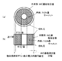
- FIGS. 1 to 6 are schematic schematic diagrams showing some embodiments of the composite sintered body cutting tool of the present invention.
- FIG. 1 shows a composite sintered body cutting tool in which the planar shape of the rake face is circular and the angle formed by the rake face and the flank is 90 degrees
- FIG. 2 shows the composite sintered body cutting tool shown in FIG. 3 shows a TiCN-based cermet layer composed of a plurality of TiCN-based cermet layers
- FIG. 3 shows a composite sintering in which the rake face has a polygonal planar shape and the rake face and flank face form an angle of 90 degrees.
- FIG. 4 shows a composite sintered body cutting tool shown in FIG.
- FIG. 3 in which the TiCN-based cermet layer is composed of a plurality of TiCN-based cermet layers
- FIG. 5 is a plan view of the rake face
- FIG. 6 shows a composite sintered body cutting tool in which the angle between the rake face and the flank is less than 90 degrees
- FIG. 6 shows the angle between the rake face and the flank. Indicates a composite sintered body cutting tool of less than 90 degrees
- the planar shape of the rake face is circular (also elliptical).
- any position on the circumference can be used as a cutting edge
- the plan shape of the rake face is a polygon ( In the case of a quadrangle or rhombus, each vertex of the square can be used as a cutting edge.
- the description of the hard coating film covering the surface of the WC-based cemented carbide layer is omitted, but in FIGS. 1 to 6, the WC-based cemented carbide is omitted. If a hard coating film is formed by a well-known film forming means on the outer peripheral portion including at least the cutting edge constituted by layers, it can be used as a surface-coated composite sintered body cutting tool.
- the cutting tool or the surface-coated composite sintered body cutting tool of the present invention can be produced, for example, by the following manufacturing method.
- a WC-based cemented carbide powder having a predetermined composition is nested on the inner peripheral side so as to have a desired WC-based cemented carbide layer width after sintering, and is the same as the shape of the WC-based cemented carbide in the cutting tool.
- the outer peripheral portion is composed of a WC-based cemented carbide, and the TiCN-based cermet is surrounded by the outer peripheral portion.
- a filled composite molded body is produced.
- TiCN-based cermet powder it is not always necessary to use one type of powder, and a plurality of types of powders having different component compositions can be used.
- a plurality of types of powders each having a different component composition may be provisionally formed in a substantially concentric arrangement, so that a so-called laminated TiCN in which a plurality of TiCN-based cermet layers are laminated concentrically.
- a base cermet temporary molded body (a structure similar to FIGS. 2A, 2B, 4A, and 4B) can be produced.
- this composite formed body is sintered under a condition of 1420 ° C. ⁇ 1 hr in a nitrogen atmosphere of 0.1 kPa, for example, to produce a composite sintered body, and then the obtained composite sintered body is predetermined.
- the cutting tool of this invention is produced by processing into the shape of. Further, at least on the surface of the WC-based cemented carbide layer of the cutting tool of the present invention produced above, a Ti compound layer, a composite nitriding of Ti and Al, by a conventionally known film forming method such as physical vapor deposition or chemical vapor deposition.
- the surface-coated composite sintered body cutting tool of the present invention can be produced by vapor-depositing a hard coating film such as a physical layer or an Al 2 O 3 layer as a single layer or as a multi-layer laminated film.
- the TiCN-based cermet layer adjacent to the WC-based cemented carbide used in the present invention is at least a cermet having TiCN as a main hard component and iron group metal (for example, Co, Ni, Fe) as a main binder phase component.
- iron group metal for example, Co, Ni, Fe
- the iron group metal component is 4 to 25% by mass
- W is less than 15% by mass
- Mo is 2 to 15% by mass
- Nb is 2 to 10% by mass
- Iron group metal components The iron group metal component is firmly bonded to the hard component in the TiCN-based cermet, and has the effect of improving the strength and toughness of the tool base, but if the content is less than 4% by mass or more than 25% by mass, the TiCN group
- the difference in the amount of the binder phase in the cermet and the WC-base cemented carbide increases, and the binder phase in the WC-base cemented carbide layer into the TiCN-base cermet layer or from the TiCN-base cermet layer into the WC-base cemented carbide layer.
- the components are greatly diffused, and the binder phase distribution of the entire tool becomes non-uniform, resulting in a lack of stability as a tool. Therefore, the iron group metal component content in the TiCN-based cermet was determined to be 4 to 25% by mass.
- W As W content in the TiCN-based cermet increases, the properties of the TiCN-based cermet approach the WC-based cemented carbide, so that sintering as a composite becomes easier, but it is contained as intended in the present invention.
- the W content is determined to be less than 15% by mass because it is a component element that requires a reduction in the amount.
- Mo is a component element that has the effect of increasing the wettability between the hard phase and the binder phase and improving the sinterability in the TiCN-based cermet, but if its content is less than 2% by mass, the effect of improving the wettability On the other hand, if the content exceeds 15% by mass, Mo dissolves in the hard phase and the strength and toughness are lowered. Therefore, the Mo content is determined to be 2 to 15% by mass.
- Nb has the effect of improving the high-temperature oxidation resistance of TiCN-based cermets, but if its content is less than 2% by mass or exceeds 10% by mass, the effect of improving high-temperature oxidation resistance is reduced. Therefore, the Nb content is determined to be 2 to 10% by mass.
- Cr has the effect of bringing the sintering temperature of the TiCN-based cermet closer to that of the WC-based cemented carbide, but if its content is less than 0.2% by mass, the effect is not sufficient, while its content is 2 When the content exceeds 20% by mass, a free phase of Cr 3 C 2 precipitates and lowers the toughness of the sintered body. Therefore, the Cr content is determined to be 0.2 to 2% by mass.
- Co is an iron group metal component and is a binder phase component in the TiCN-based cermet, but in the relationship with Ni, which is also an iron group metal component, the Co content ratio (Co / (Co + Ni)) must be in the range of 0.5 to 0.8 (mass ratio).
- the content ratio of Co to the total content of Co and Ni (Co / (Co + Ni)) is less than 0.5, the TiCN-based cermet and the WC-based cemented carbide composite body are sintered when the TiCN-based composite body is sintered.
- the Ni component in the cermet diffuses into the WC-based cemented carbide and reduces the high-temperature hardness of the WC-based cemented carbide, while the Co content ratio (Co / (Co + Ni) with respect to the total content of Co and Ni. )) Exceeds 0.8, the toughness of the TiCN-based cermet is lowered, and the composite sintered body may be damaged. Therefore, for Co and Ni as components contained in the TiCN-based cermet, the Co content ratio (Co / (Co + Ni)) with respect to the total content of Co and Ni is 0.5 to 0.8 (however, the mass ratio) ).
- the component composition of the TiCN-based cermet layer adjacent to the WC-based cemented carbide layer is as described above.
- the TiCN-based cermet does not need to be entirely composed of the component composition described above. That is, as shown in FIGS. 2A and 2B or FIGS. 4A and 4B, the TiCN-based cermet layer can be configured as a laminate of a plurality of TiCN-based cermet layers. 2 (a), 2 (b) or 4 (a), 4 (b), the TiCN-based cermet layer is configured as a two-layered laminate of “TiCN-based cermet layer 1” and “TiCN-based cermet layer 2”.
- the TiCN-based cermet layer can also be configured as a laminate of two or more TiCN-based cermet layers.
- TiCN-based cermet layer that is, “TiCN-based cermet layer 1” shown in FIGS. 2A and 2B or FIGS. 4A and 4B
- the component composition must be determined as described above, but the TiCN-based cermet layer that is not in direct contact with the WC-based cemented carbide (that is, in FIGS. 2A and 2B or FIGS. 4A and 4B).
- the "TiCN-based cermet layer 2" shown may be a component composition of a commonly used TiCN-based cermet.
- TiCN group cermet for example, ZrC, TaC etc.
- W content it is 8 mass% or less, Preferably, it can be 4 mass% or less.
- W content contained in the TiCN-based cermet can be further reduced without deteriorating the cutting performance of the composite sintered body cutting tool and the surface-coated composite sintered body cutting tool. The effect of reducing the amount of use becomes large.
- the WC-based cemented carbide constituting the composite sintered body with the TiCN-based cermet is composed of WC as a main hard phase component and an iron group metal (for example, Co, Ni, Fe) as a main binder phase component.
- the binder phase component is firmly bonded to the hard phase component and has an effect of improving the strength and toughness of the tool base.
- the content is less than 4% by mass, a desired effect cannot be obtained in the above-described operation,
- the wear resistance decreases, so the total content of iron group metals (for example, Co, Ni, Fe) as a binder phase component is 4 to 17% by mass. %.
- Each component of Ti, Zr, Nb, Ta and Cr forms carbides, nitrides, carbonitrides, etc., and has the effect of increasing the hardness of the WC-based cemented carbide and improving the wear resistance.
- the toughness will decrease, so the content of each component of Ti, Zr, Nb, Ta and Cr The total amount is preferably 10% by mass or less.
- the WC-based cemented carbide constituting the outer periphery including the cutting edge:
- the WC cemented carbide layer constitutes the outer periphery including the cutting edge, so that the cutting edge and the flank are formed by the WC-based cemented carbide layer.
- the main part of the rake face of the cutting tool is composed of the TiCN-based cermet layer by filling the inside surrounded by the outer peripheral portion with the TiCN-based cermet layer.
- the angle formed by the rake face and the flank face of the tool is 90 degrees or less than 90 degrees, and can be applied to both so-called negative inserts and positive inserts.
- the WC-based cemented carbide layer in the outer peripheral portion including the cutting edge has a maximum inscribed circle diameter of the rake face of the composite sintered body of 0.03 to The width is 0.15 times. This is because when the width of the WC-based cemented carbide layer is less than 0.03 times the maximum inscribed circle diameter of the rake face in the composite sintered body, a large load is applied to the TiCN-based cermet that is inferior in toughness during cutting.
- the width of the WC-based cemented carbide layer exceeds 0.15 times the maximum inscribed circle diameter of the rake face in the composite sintered body, the WC-based cemented carbide is formed. This is because the residual compressive stress formed in the alloy layer is reduced, chipping resistance and chipping resistance are deteriorated, and it is not suitable for the purpose of the present invention of reducing the amount of W used. Therefore, in the present invention, the width of the WC-based cemented carbide is 0.03 to 0.15 times the maximum inscribed circle diameter of the rake face in the composite sintered body.
- the cutting tool of the present invention can be used as a cutting tool as it is by making the WC-based cemented carbide layer of the composite sintered body an outer peripheral portion including a cutting edge (that is, a cutting edge and a flank). At least on the surface of the WC-based cemented carbide layer constituting the outer peripheral portion including the cutting edge (that is, the cutting edge and the flank), for example, a composite nitride layer of Ti and Al by physical vapor deposition, chemical vapor deposition, or the like. By forming a coating, cutting performance can be further improved.
- a hard coating film not only a composite nitride layer of Ti and Al, but also a nitride layer of Ti, a carbide layer, a carbonitride layer, a composite nitride layer of Al and Cr, an Al 2 O 3 layer, etc.
- Various known hard coating films can be formed as a single layer or as a laminate of a plurality of layers.
- the present invention relates to a composite sintered body cutting tool or a surface-coated composite sintered body cutting tool comprising a composite sintered body of a TiCN-based cermet layer and a WC-based cemented carbide layer, wherein the TiCN-based cermet layer and the WC-based cemented carbide cutting tool are used.
- the schematic diagram of the composite sintered compact cutting tool which is one aspect of the composite sintered compact cutting tool of this invention is shown,
- This example shows that the planar shape of the rake face is circular, and the angle formed by the rake face and the flank face Is a 90 degree composite sintered body cutting tool, (a) is a plan view and (b) is a side view.
- the TiCN-based cermet is composed of a plurality of TiCN-based cermet layers.
- (A) is a plan view and (b) is a side view.
- the schematic diagram of the composite sintered compact cutting tool which is the other aspect of the composite sintered compact cutting tool of this invention is shown,
- This example shows that the planar shape of the rake face is a polygon, and the rake face and the flank face are formed.
- It is a composite sintered compact cutting tool whose angle is 90 degrees, (a) is a plan view and (b) is a side view.
- the TiCN base cermet is composed of a plurality of TiCN base cermet layers.
- (A) is a plan view and (b) is a side view.
- the schematic diagram of the composite sintered compact cutting tool which is the other aspect of the composite sintered compact cutting tool of this invention is shown, This example shows that the planar shape of the rake face is circular, and the angle formed by the rake face and the flank face Is a composite sintered body cutting tool of less than 90 degrees, (a) is a plan view and (b) is a side view.
- the schematic diagram of the composite sintered compact cutting tool which is the other aspect of the composite sintered compact cutting tool of this invention is shown, This example shows that the planar shape of the rake face is a polygon, and the rake face and the flank face are formed. It is a composite sintered compact cutting tool whose angle is less than 90 degrees, (a) is a plan view, and (b) is a side view.
- a composite sintered compact cutting tool having a structure shown in FIG. 1 or 2 (that is, a so-called negative insert in which the planar shape of the rake face is circular and the angle between the rake face and the flank face is 90 degrees) is as follows. It was produced in the process.
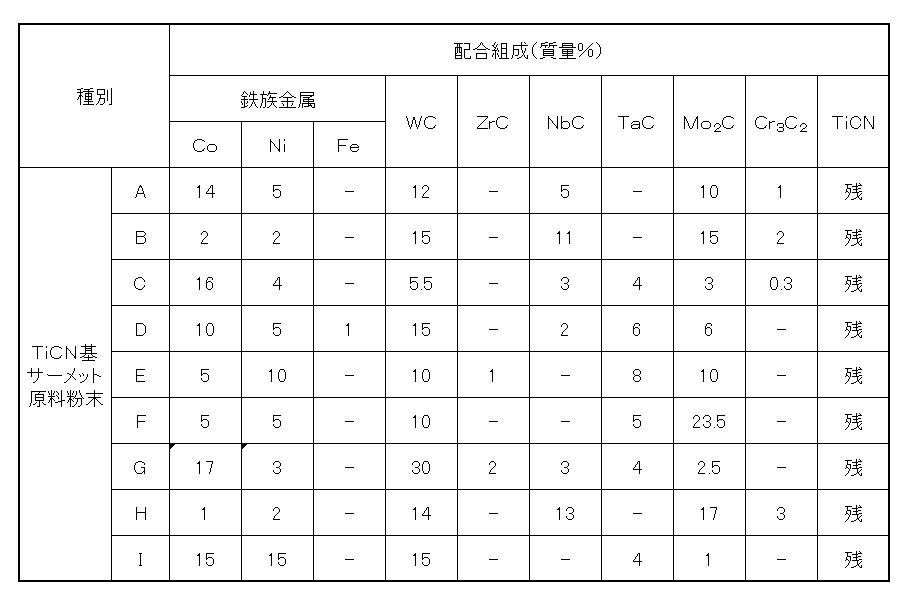
- a WC-based cemented carbide raw material powder having an average particle size of 0.5 to 3 ⁇ m having a composition shown in Table 1 is prepared.
- a TiCN-based cermet raw material powder having an average particle size of 0.5 to 3 ⁇ m having the composition shown in Table 2.
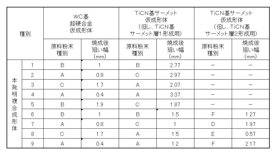
- the WC-based cemented carbide raw material powder is pressed using a material mold for ISO insert shape RNMA 120400 and a nest for providing a gap in the inner peripheral portion, thereby producing temporary molded bodies 1 to 9 shown in Table 3. did.
- the TiCN-based cermet raw material powder is arranged on the inner periphery of the temporary molded bodies 1 to 9, and pressed together with the temporary molded bodies 1 to 9 with the material mold of ISO insert shape RNMA 120400 in the combinations shown in Table 3. Composite molded bodies 1 to 9 were produced.
- the temporary molded bodies 6 to 9 are filled with a plurality of types of TiCN-based cermet raw material powders so that each TiCN-based cermet raw material powder is substantially concentric with respect to the center, Temporary molded articles shown in Table 3 were produced.
- the produced composite compacts 1 to 9 are composite compacts 1 to 5 composed of a WC-based cemented carbide raw material powder and one kind of TiCN-based cermet raw material powder, a WC-based cemented carbide raw material powder and a TiCN-based cermet layer.
- the composite molded bodies 1 to 9 were sintered to produce composite sintered bodies 1 to 9.
- the sintering conditions are as follows.
- the temperature is raised from room temperature to 1280 ° C. at a rate of 5 ° C./min, and the temperature range from 1280 ° C. to 1380 ° C. at which the liquid phase appears is Also, the temperature is increased at a high rate of 30 ° C./min or higher, the temperature is increased from 1380 ° C. to a predetermined 1420 ° C. at a rate of 5 ° C./min, and in a nitrogen atmosphere of 0.1 kPa, 1420 ° C.
- RNMA 120400-shaped composite sintered body cutting tools 1 to 9 (hereinafter referred to as the present invention tools 1 to 9) shown in Table 6 were produced.
- the WC-based cemented carbide layer is separated from the interface between the WC-based cemented carbide layer and the TiCN-based cermet layer using an electron beam microanalyzer.
- Composition analysis is performed at a position of 100 ⁇ m on the inner side of the hard alloy layer and at a position of 100 ⁇ m on the inner side of the TiCN-based cermet layer, and an average value of 10-point measurement is obtained to obtain a WC-based cemented carbide layer and a TiCN.
- the component composition of the base cermet layer was determined.
- the position of 100 ⁇ m from the interface between the WC-based cemented carbide layer and the TiCN-based cermet layer 1 to the inner side of the WC-based cemented carbide layer, and the TiCN-based cermet layer 1 Perform composition analysis at a position of 100 ⁇ m on the inner side, and further at the position of 100 ⁇ m from the interface between the TiCN-based cermet layer 1 and the TiCN-based cermet layer 2 to the inner side of the TiCN-based cermet layer 2, and obtain an average value of 10-point measurement
- the component compositions of the WC-based cemented carbide layer, the TiCN-based cermet layer 1 and the TiCN-based cermet layer 2 were determined. Tables 5 and 6 show these values.
- the widths of the WC-based cemented carbide layer and the TiCN-based cermet layer of the inventive tools 1 to 5 and the WC-based cemented carbide layer, the TiCN-based cermet layer 1 and the TiCN-based cermet layer 2 of the inventive tools 6 to 9 are also shown.
- the width was measured by observing with an optical microscope, and the widths measured at five different points were averaged to obtain the width. Tables 5 and 6 show these values.
- the surface of the WC-based cemented carbide layer was subjected to arc ion plating to form a composite nitride of Ti and Al (note that the contents of Ti and Al are respectively 50 atomic%) was formed by vapor deposition.
- Tables 5 and 6 show the film thickness of the hard coating film formed by vapor deposition.
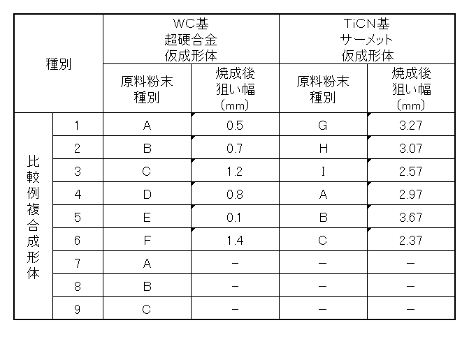
- the WC-based cemented carbide raw material powder having the composition shown in Table 1 and the TiCN-based cermet raw material powder having the composition shown in Table 2 were preliminarily molded in the same manner as in Example 1 with the combinations shown in Table 4.
- the composites 1 to 6 were produced by pressing the compacts 1 to 6 and then pressed, and then the composite compacts were sintered under the same conditions as in Example 1 to produce the composites of the comparative examples. Sintered bodies 1 to 6 were produced.
- the component compositions of the WC-based cemented carbide layer and the TiCN-based cermet layer were determined. Further, the widths of the WC-based cemented carbide layer and the TiCN-based cermet layer of Comparative Tools 1 to 6 were measured by observing with an optical microscope, and the widths measured at five different points were averaged to obtain an average width. Table 7 shows these values.
- the surface of the WC-based cemented carbide layer was subjected to arc ion plating to form a composite nitride of Ti and Al (note that the contents of Ti and Al are 50 atom% each).
- a hard coating film was formed by vapor deposition.
- Table 7 shows the film thickness of the hard coating film formed by vapor deposition.
- the tool of the present invention optimizes the component composition range of the TiCN-based cermet layer and the WC-based cemented carbide layer and includes a cutting edge even if the amount of tungsten used is reduced.
- the width ratio of the WC-based cemented carbide layer that forms the outer periphery By optimizing the width ratio of the WC-based cemented carbide layer that forms the outer periphery, intermittent and impactful high loads act on the cutting edge without reducing thermal crack resistance, and thermal loads are also reduced.
- Produced only from WC-based cemented carbides, which suppresses the propagation and propagation of cracks in wet interrupted cutting of working alloy steel, etc. exhibits excellent abnormal damage resistance and wear resistance over a long period of use.
- the cutting performance is not inferior to that of the comparative example tool 7 (that is, a tool with a used W amount reduction rate of zero%). Further, from the viewpoint of abnormal damage resistance, the tools 1 to 9 of the present invention have superior abnormal damage resistance compared to the comparative tools 7 to 9. On the other hand, although the comparative tools 1 to 6 have a reduced amount of tungsten used, they have poor thermal crack resistance, and it is clear that they reach the service life in a short time.
- a composite sintered body cutting tool having the structure shown in FIG. 3 or FIG. 4 (that is, a so-called negative insert in which the plane shape of the rake face is a polygon and the angle between the rake face and the flank face is 90 degrees) Produced in the process.
- a WC-based cemented carbide raw material powder having an average particle size of 0.5 to 3 ⁇ m having a composition shown in Table 1 is prepared.
- the WC-based cemented carbide raw material powder was pressed using a material mold for ISO insert shape SNMN120408 and a nest for providing a gap in the inner peripheral portion, thereby producing temporary molded bodies 11 to 19 shown in Table 9. .
- the TiCN-based cermet raw material powder is arranged on the inner periphery of the temporary molded bodies 11 to 19, and is pressed together with the temporary molded bodies 11 to 19 with a material mold of ISO insert shape SNMN120408, and the composite molded body 11 19 were produced.
- the temporary molded bodies 16 to 19 are filled with plural types of TiCN-based cermet raw material powders so that the center positions of the respective TiCN-based cermet raw material powders are substantially the same position. 9 was produced.
- the produced composite compacts 11 to 19 are composite compacts 11 to 15 composed of a WC-based cemented carbide raw material powder and one type of TiCN-based cermet raw material powder, a WC-based cemented carbide raw material powder, and a TiCN-based cermet layer.
- the composite molded bodies 11 to 19 were sintered under the same conditions as in Example 1 to produce composite sintered bodies 11 to 19 and subjected to honing processing similar to that in Example 1, so that Table 11, SNMN120408-shaped composite sintered body cutting tools 11 to 19 (hereinafter referred to as the present invention tools 11 to 19) shown in Table 12 were produced.
- the composition of the WC-based cemented carbide layer and the TiCN-based cermet layer or the TiCN-based cermet layer 1 and the TiCN-based cermet layer 2 was determined for the above-described inventive tools 11 to 19 in the same manner as in Example 1. Further, the widths of the WC-based cemented carbide layer and the TiCN-based cermet layer, and the widths of the TiCN-based cermet layer 1 and the TiCN-based cermet layer 2 are observed and measured with an optical microscope. An average width was obtained. Tables 11 and 12 show these values.
- the surface of the WC-based cemented carbide layer was subjected to arc ion plating to form a composite nitride of Ti and Al (note that the contents of Ti and Al are respectively 50 atomic%) was formed by vapor deposition.
- Table 10 shows the film thickness of the hard coating film formed by vapor deposition.
- the WC-based cemented carbide raw material powder having the composition shown in Table 1 and the TiCN-based cermet raw material powder having the composition shown in Table 2 were preliminarily molded in the same manner as in Example 1 with the combinations shown in Table 10.
- the composite bodies 11 to 16 were prepared, and further pressed to produce comparative example composite molded bodies 11 to 16, and then this composite molded body was sintered under the same conditions as in Example 1. Sintered bodies 11 to 16 were produced.
- comparative sintered bodies 17 to 19 made of only the WC-based cemented carbide were produced only from the WC-based cemented carbide raw material powder having the composition shown in Table 1.
- honing was performed under the same conditions as in Example 1 to produce SNMN120408-shaped composite sintered body cutting tools 11 to 19 (hereinafter referred to as Comparative Example Tools 11 to 19) shown in Table 13.
- the component compositions of the WC-based cemented carbide layer and the TiCN-based cermet layer were determined in the same manner as in Example 1.
- the widths of the WC-based cemented carbide layer and the TiCN-based cermet layer were also determined. Table 13 shows these values.
- the surface of the WC-based cemented carbide layer was subjected to arc ion plating to form a composite nitride of Ti and Al (note that the contents of Ti and Al are 50 atom% each).
- a hard coating film made of was formed by vapor deposition.
- Table 13 shows the film thickness of the hard coating film formed by vapor deposition.
- the tool of the present invention optimizes the component composition ranges of the TiCN-based cermet layer and the WC-based cemented carbide layer and includes a cutting edge even if the amount of tungsten used is reduced.
- the thickness ratio of the WC-based cemented carbide layer that forms the outer periphery By optimizing the thickness ratio of the WC-based cemented carbide layer that forms the outer periphery, intermittent and impactful high loads act on the cutting edge without reducing thermal cracking resistance, and thermal loads are also reduced. In wet intermittent cutting of working alloy steel, crack propagation and progress are suppressed, and excellent abnormal damage resistance and wear resistance are exhibited over a long period of use.
- the comparative tools 11 to 16 have a reduced use amount of tungsten, they have poor thermal cracking resistance and have reached the service life in a short time.
- the amount used has not been reduced, and the wear resistance is equivalent to the tool of the present invention, but it is clear that the abnormal damage resistance is inferior.
- a positive insert was prepared according to the following procedure.
- a WC-based cemented carbide raw material powder having an average particle size of 0.5 to 3 ⁇ m having a composition shown in Table 1 is prepared.
- the WC-based cemented carbide raw material powder is pressed using a material mold of ISO insert shape RGEN2004M0EN and a nest for providing a gap in the inner peripheral portion, and temporary molded bodies 21 to 25 shown in Table 15 are produced. did.
- the TiCN-based cermet raw material powder is arranged on the inner periphery of the temporary molded bodies 21 to 25, and is pressed together with the temporary molded bodies 21 to 25 with a material mold of ISO insert shape RGEN2004M0EN. To 25 were produced.
- the above WC-based cemented carbide powder was pressed using a material mold of ISO insert shape SEEN1203AFEN1 and a nest for providing a gap in the inner peripheral portion, thereby producing temporary molded bodies 26 to 30 shown in Table 15. .
- the TiCN-based cermet raw material powder is disposed on the inner periphery of the temporary molded bodies 26 to 30 and pressed together with the temporary molded bodies 26 to 30 with a material mold of ISO insert shape SEEN1203AFEN1, and the composite molded body 26 30 were produced.
- the composite compacts 21 to 30 are sintered under the same conditions as in Example 1 to produce composite sintered bodies 21 to 30.
- R 0.04 honing is performed to form the cutting edge, and RGEN2004M0EN-shaped composite sintered body cutting tools 21 to 25 (hereinafter referred to as the present invention tool 21 to 25) and SEEN1203AFEN1-shaped composite sintered body shown in Table 16 Cutting tools 26 to 30 (hereinafter referred to as the present invention tools 26 to 30) were produced.
- the composition of the WC-based cemented carbide layer and the TiCN-based cermet layer was determined for the inventive tools 21 to 30 in the same manner as in Example 1. Further, the maximum thickness and the minimum thickness of the WC-based cemented carbide layer and the TiCN-based cermet layer were measured with an optical microscope, and the widths measured at five different points were averaged to obtain an average width. Table 16 shows these values.
- the surface of the WC-based cemented carbide layer was subjected to arc ion plating to form a composite nitride of Ti and Al (note that the contents of Ti and Al are respectively 50 atomic%) was formed by vapor deposition.
- Table 16 shows the film thickness of the hard coating film formed by vapor deposition.
- the tool of the present invention optimizes the component composition range of the TiCN-based cermet layer and the WC-based cemented carbide layer, and includes an outer periphery including a cutting edge.
- the thickness ratio of the WC-based cemented carbide layer that constitutes the part By optimizing the thickness ratio of the WC-based cemented carbide layer that constitutes the part, intermittent and impactful high loads act on the cutting edge without deteriorating the thermal crack resistance, and thermal loads also act It can be seen that, in wet intermittent cutting of alloy steel, etc., the propagation and propagation of cracks is suppressed, and excellent abnormal damage resistance and wear resistance are exhibited over a long period of use.
- the cutting tool of the present invention using a composite sintered body as a tool base can reduce the amount of tungsten, which is a rare metal, and is a wet intermittent operation in which intermittent and impact high loads and thermal loads act on the cutting edge. Even when used for cutting, it has excellent thermal cracking resistance, and can exhibit excellent cutting performance over a long period of use without causing abnormal damage such as chipping, chipping, peeling, etc. It can cope with cost reduction sufficiently.
Landscapes
- Engineering & Computer Science (AREA)
- Mechanical Engineering (AREA)
- Chemical & Material Sciences (AREA)
- Materials Engineering (AREA)
- Manufacturing & Machinery (AREA)
- Metallurgy (AREA)
- Organic Chemistry (AREA)
- Composite Materials (AREA)
- Cutting Tools, Boring Holders, And Turrets (AREA)
- Powder Metallurgy (AREA)
Abstract
タングステン使用量を削減したTiCN基サーメットとWC基超硬合金からなる複合焼結体切削工具を提供する。 上記複合焼結体切削工具の切れ刃を含む外周部は、鉄族金属成分を4~17質量%、残部はWCを主たる硬質相成分とするWC基超硬合金層で構成され、また、外周部に囲繞された内部はTiCN基サーメット層で構成され、上記外周部の幅は、すくい面の最大内接円直径の0.03~0.15倍であり、WC基超硬合金層と隣接するTiCN基サーメット層は、該サーメットの構成成分の含有割合を金属成分の含有割合で表現した場合、少なくとも鉄族金属成分を4~25質量%、Wを15質量%未満、Moを2~15質量%、Nbを2~10質量%、Crを0.2~2質量%を含有し、かつ、鉄族金属成分であるCoとNiについて、CoとNiの合計含有量に対するCo含有割合は0.5~0.8(但し、質量比)を満足する複合焼結体切削工具。
Description
この発明は、TiCN基サーメットとWC基超硬合金の複合焼結体からなる切削工具に関し、特に、希少金属であるタングステンの使用量の削減を図るとともに、焼結に際しての焼結体の変形量を少なくした切削性能にすぐれる切削工具に関するものである。
本願は、2015年5月28日に日本に出願された特願2015-108977号に基づき優先権を主張し、その内容をここに援用する。
本願は、2015年5月28日に日本に出願された特願2015-108977号に基づき優先権を主張し、その内容をここに援用する。
鋼や鋳鉄の切削加工用工具としては、WC基超硬合金が広く利用されているが、希少金属であるタングステンの使用量を削減し所望の切削性能を得るために、従来から各種の提案がなされている。
例えば、特許文献1には、超硬合金層と、WC及びWを合計で15~65質量%以下含み、結合相中の鉄族金属の80質量%以上がCoであるサーメット層とを積層した基材からなる切削工具において、基材は、積層方向における最大厚さをh1、切刃部分の超硬合金層の積層方向における最大厚さをh2としたとき、h2/h1を0.002~0.02とすることによって、耐衝撃性と仕上げ面光沢を改善した複合焼結体製切削工具が提案されている。
また、例えば、特許文献2には、超硬合金層と、WC及びWを合計で15~65質量%以下含み、結合相中の鉄族金属の80質量%以上がCoであるサーメット層とを積層した基材からなる切削工具において、超硬合金層とサーメット層との境界に最大落差が50μm~500μmである凹凸部を形成し、かつ、基材の積層方向における最大厚さをh1、すくい面側に配置された超硬合金層の積層方向における最大厚さをh2としたとき、h2/h1を0.02超0.4以下とすることにより、超硬合金層とサーメット層との間の接合性を改善するとともに、焼結後の基材の変形を抑制した複合焼結体製切削工具が提案されている。
また、例えば、特許文献3には、超硬合金粉末とサーメット粉末からそれぞれプレス成形体を形成し、このプレス成形体を積層して、真空雰囲気で1300~1500℃×0.5~3時間保持する焼結を行って工具基体を作製するにあたり、超硬合金層とサーメット層との境界の凹凸状態を特定の範囲とし、あるいは、両層の結合相量を特定の範囲に調整することにより、超硬合金とサーメットの接合性を高め、また、焼結時に生じる変形を抑制し、複合焼結体製切削工具の耐摩耗性と靭性を改善することが提案されている。
上記特許文献1,2に示すような複合焼結体製切削工具では、タングステン使用量のある程度の低減は図られるものの、サーメット中には、15質量%以上のW,WCが必要とされており、タングステン使用量の削減は不十分であり、また、このような切削工具を湿式断続切削加工に用いた場合には、強度、靭性が不十分であるばかりか耐熱亀裂性も十分でないため、チッピング、欠損等の異常損傷を破損し易いという問題があった。
また、上記特許文献3に示す超硬合金とサーメットからなる複合焼結体において、超硬合金層とサーメット層との境界に凹凸を形成する必要があるばかりか、焼結時の変形が少ない複合焼結体を得るためには、プレス体の焼結時の収縮特性が異種材料間で揃っている必要があり、そのため、かかる複合焼結体から作製した切削工具では、タングステン使用量の低減はせいぜい30%程度に留まっており、省資源の観点からは十分満足できるものではないばかりか、湿式断続切削などの激しい熱履歴を受ける切削条件下では、クラックの進展等により刃先の超硬合金が破壊する恐れがあり、十分な信頼性があるとはいえなかった。
そこで、本発明では、TiCN基サーメットとWC基超硬合金からなる複合焼結体を工具基体とする切削工具において、希少金属であるタングステンの使用量の低減を図るとともに、切れ刃に断続的・衝撃的な高負荷が作用する断続切削に用いた場合でも、クラック進展抑制作用を備え、耐異常損傷性に優れた切削工具を提供することを目的とする。
また、上記特許文献3に示す超硬合金とサーメットからなる複合焼結体において、超硬合金層とサーメット層との境界に凹凸を形成する必要があるばかりか、焼結時の変形が少ない複合焼結体を得るためには、プレス体の焼結時の収縮特性が異種材料間で揃っている必要があり、そのため、かかる複合焼結体から作製した切削工具では、タングステン使用量の低減はせいぜい30%程度に留まっており、省資源の観点からは十分満足できるものではないばかりか、湿式断続切削などの激しい熱履歴を受ける切削条件下では、クラックの進展等により刃先の超硬合金が破壊する恐れがあり、十分な信頼性があるとはいえなかった。
そこで、本発明では、TiCN基サーメットとWC基超硬合金からなる複合焼結体を工具基体とする切削工具において、希少金属であるタングステンの使用量の低減を図るとともに、切れ刃に断続的・衝撃的な高負荷が作用する断続切削に用いた場合でも、クラック進展抑制作用を備え、耐異常損傷性に優れた切削工具を提供することを目的とする。
本発明者等は、上述のような観点から、TiCN基サーメットとWC基超硬合金からなる複合焼結体を工具基体とする複合焼結体切削工具において、タングステン使用量の低減を図るとともに、切れ刃に断続的・衝撃的な高負荷が作用する断続切削に用いた場合でも、クラックの伝播・進展抑制作用に優れ、もって、長期の使用に亘ってチッピング、欠損、剥離等の異常損傷を発生しない切削工具について鋭意検討したところ、次のような知見を得た。
即ち、TiCN基サーメットとWC基超硬合金の複合焼結体切削工具において、工具の切れ刃を含む外周部(逃げ面)をWC基超硬合金で構成し、該WC基超硬合金からなる外周部(逃げ面)の内部にTiCN基サーメットを充填することにより複合焼結体切削工具を構成した場合には、複合焼結体の焼結時の熱膨張率差で、内部のTiCN基サーメットによって、切れ刃を含む外周部を構成するWC基超硬合金には圧縮応力が形成され、これによって、工具の断続切削性能が改善されることを見出したのである。
そしてこの場合、切削工具全体がWC基超硬合金で構成されているものに比して、タングステンの使用量の大幅な低減を図り得るのである。
つまり、本発明者らは、上記構造の複合焼結体を工具基体とする切削工具においては、希少金属であるタングステンの使用量を大幅に低減できるとともに、切れ刃に断続的・衝撃的な高負荷および熱的負荷が作用する合金鋼等の湿式断続切削においても、クラックの伝播・進展が防止され、長期の使用に亘って、すぐれた耐異常損傷性、耐摩耗性を発揮することを見出したのである。
即ち、TiCN基サーメットとWC基超硬合金の複合焼結体切削工具において、工具の切れ刃を含む外周部(逃げ面)をWC基超硬合金で構成し、該WC基超硬合金からなる外周部(逃げ面)の内部にTiCN基サーメットを充填することにより複合焼結体切削工具を構成した場合には、複合焼結体の焼結時の熱膨張率差で、内部のTiCN基サーメットによって、切れ刃を含む外周部を構成するWC基超硬合金には圧縮応力が形成され、これによって、工具の断続切削性能が改善されることを見出したのである。
そしてこの場合、切削工具全体がWC基超硬合金で構成されているものに比して、タングステンの使用量の大幅な低減を図り得るのである。
つまり、本発明者らは、上記構造の複合焼結体を工具基体とする切削工具においては、希少金属であるタングステンの使用量を大幅に低減できるとともに、切れ刃に断続的・衝撃的な高負荷および熱的負荷が作用する合金鋼等の湿式断続切削においても、クラックの伝播・進展が防止され、長期の使用に亘って、すぐれた耐異常損傷性、耐摩耗性を発揮することを見出したのである。
本発明は、上記知見に基づいてなされたものであって、
「(1)TiCN基サーメット層とWC基超硬合金層との複合焼結体からなる切削工具において、
(a)上記切削工具は、すくい面の平面形状が円形または多角形であり、すくい面と逃げ面のなす角度は90度または90度未満であり、
(b)上記切削工具の切れ刃を含む外周部は、鉄族金属成分を4~17質量%、残部はWCを主たる硬質相成分とするWC基超硬合金層で構成され、また、外周部に囲繞された内部はTiCN基サーメット層で構成され、
(c)上記WC基超硬合金層からなる外周部の幅は、上記複合焼結体におけるすくい面の最大内接円直径の0.03~0.15倍であり、
(d)上記WC基超硬合金層からなる外周部で囲繞された内部のTiCN基サーメット層は、少なくとも1層以上のTiCN基サーメット層から構成され、WC基超硬合金層と隣接するTiCN基サーメット層は、該サーメットの構成成分の含有割合を金属成分の含有割合で表現した場合、少なくとも鉄族金属成分を4~25質量%、Wを15質量%未満、Moを2~15質量%、Nbを2~10質量%、Crを0.2~2質量%を含有し、かつ、鉄族金属成分であるCoとNiについて、CoとNiの合計含有量に対するCo含有割合は0.5~0.8(但し、質量比)を満足することを特徴とする複合焼結体切削工具。
(2)前記TiCN基サーメット層とWC基超硬合金層とからなる複合焼結体の少なくともWC基超硬合金層の表面に、硬質被覆膜が形成されていることを特徴とする前記(1)に記載の表面被覆複合焼結体切削工具。」
を特徴とするものである。
「(1)TiCN基サーメット層とWC基超硬合金層との複合焼結体からなる切削工具において、
(a)上記切削工具は、すくい面の平面形状が円形または多角形であり、すくい面と逃げ面のなす角度は90度または90度未満であり、
(b)上記切削工具の切れ刃を含む外周部は、鉄族金属成分を4~17質量%、残部はWCを主たる硬質相成分とするWC基超硬合金層で構成され、また、外周部に囲繞された内部はTiCN基サーメット層で構成され、
(c)上記WC基超硬合金層からなる外周部の幅は、上記複合焼結体におけるすくい面の最大内接円直径の0.03~0.15倍であり、
(d)上記WC基超硬合金層からなる外周部で囲繞された内部のTiCN基サーメット層は、少なくとも1層以上のTiCN基サーメット層から構成され、WC基超硬合金層と隣接するTiCN基サーメット層は、該サーメットの構成成分の含有割合を金属成分の含有割合で表現した場合、少なくとも鉄族金属成分を4~25質量%、Wを15質量%未満、Moを2~15質量%、Nbを2~10質量%、Crを0.2~2質量%を含有し、かつ、鉄族金属成分であるCoとNiについて、CoとNiの合計含有量に対するCo含有割合は0.5~0.8(但し、質量比)を満足することを特徴とする複合焼結体切削工具。
(2)前記TiCN基サーメット層とWC基超硬合金層とからなる複合焼結体の少なくともWC基超硬合金層の表面に、硬質被覆膜が形成されていることを特徴とする前記(1)に記載の表面被覆複合焼結体切削工具。」
を特徴とするものである。
以下、この発明について、詳細に説明する。
図1~図6は、いずれも、この発明の複合焼結体切削工具の幾つかの実施の形態を示す概略模式図である。
図1は、すくい面の平面形状が円形であり、すくい面と逃げ面のなす角度が90度の複合焼結体切削工具を示し、図2は、図1に示される複合焼結体切削工具において、TiCN基サーメット層を複数のTiCN基サーメット層で構成したものを示し、図3は、すくい面の平面形状が多角形であり、すくい面と逃げ面のなす角度が90度の複合焼結体切削工具を示し、図4は、図3に示される複合焼結体切削工具において、TiCN基サーメット層を複数のTiCN基サーメット層で構成したものを示し、図5は、すくい面の平面形状が円形であり、すくい面と逃げ面のなす角度が90度未満の複合焼結体切削工具を示し、図6は、すくい面の平面形状が多角形状であり、すくい面と逃げ面のなす角度が90度未満の複合焼結体切削工具を示す。
この発明の複合焼結体切削工具(以下、「切削工具」ともいう)においては、図1(a)、図2(a)に示すように、すくい面の平面形状が、円形(楕円形も含む)の場合には、円周上のいかなる位置も切れ刃として使用することができ、また、図3(a)、図4(a)に示すように、すくい面の平面形状が多角形(四角形、あるいは、ひし形等)の場合には、角形の各頂点を切れ刃として使用することができる。
なお、図1~図6に示す切削工具では、WC基超硬合金層の表面に被覆する硬質被覆膜についての記載を省略しているが、図1~図6において、WC基超硬合金層で構成された少なくとも切れ刃を含む外周部に対して、周知の成膜手段で硬質被覆膜を形成すれば、表面被覆複合焼結体切削工具として使用することができる。
図1は、すくい面の平面形状が円形であり、すくい面と逃げ面のなす角度が90度の複合焼結体切削工具を示し、図2は、図1に示される複合焼結体切削工具において、TiCN基サーメット層を複数のTiCN基サーメット層で構成したものを示し、図3は、すくい面の平面形状が多角形であり、すくい面と逃げ面のなす角度が90度の複合焼結体切削工具を示し、図4は、図3に示される複合焼結体切削工具において、TiCN基サーメット層を複数のTiCN基サーメット層で構成したものを示し、図5は、すくい面の平面形状が円形であり、すくい面と逃げ面のなす角度が90度未満の複合焼結体切削工具を示し、図6は、すくい面の平面形状が多角形状であり、すくい面と逃げ面のなす角度が90度未満の複合焼結体切削工具を示す。
この発明の複合焼結体切削工具(以下、「切削工具」ともいう)においては、図1(a)、図2(a)に示すように、すくい面の平面形状が、円形(楕円形も含む)の場合には、円周上のいかなる位置も切れ刃として使用することができ、また、図3(a)、図4(a)に示すように、すくい面の平面形状が多角形(四角形、あるいは、ひし形等)の場合には、角形の各頂点を切れ刃として使用することができる。
なお、図1~図6に示す切削工具では、WC基超硬合金層の表面に被覆する硬質被覆膜についての記載を省略しているが、図1~図6において、WC基超硬合金層で構成された少なくとも切れ刃を含む外周部に対して、周知の成膜手段で硬質被覆膜を形成すれば、表面被覆複合焼結体切削工具として使用することができる。
この発明の切削工具あるいは表面被覆複合焼結体切削工具は、例えば、以下の製造方法によって作製することができる。
まず、所定組成を有するWC基超硬合金粉末を、焼結後所望のWC基超硬合金層の幅となるよう内周側に入れ子を用い、切削工具におけるWC基超硬合金の形状と同一の外周形状になるようにプレスで仮成形してWC基超硬合金仮成形体を作製し、次いで、所定組成を有する少なくとも1種類以上のTiCN基サーメット粉末を用意し、該TiCN基サーメット粉末を上記WC基超硬合金仮成形体の内周部に配置した状態で複合プレス成形することにより、外周部がWC基超硬合金で構成され、その外周部によって囲繞される内部にTiCN基サーメットが充填された複合成形体を作製する。
なお、TiCN基サーメット粉末については、必ずしも1種類の粉末を用いる必要はなく、成分組成の異なる複数種類の粉末を用いることができる。この場合には、それぞれ成分組成の異なる複数種類の粉末を、ほぼ同心円状に配置した状態で仮成形すればよく、これにより、謂わば複数のTiCN基サーメット層が同心円状に積層された積層TiCN基サーメット仮成形体(図2(a)、(b),図4(a)、(b)に類似する構造)を作製することができる。
ついで、この複合成形体を、例えば、0.1kPaの窒素雰囲気中にて、1420℃×1hrの条件で焼結して複合焼結体を作製し、ついで、得られた複合焼結体を所定の形状に加工することで本発明の切削工具を作製する。
また、上記で作製した本発明の切削工具の少なくともWC基超硬合金層の表面に、物理蒸着法、化学蒸着法等の従来周知の成膜法により、Ti化合物層、TiとAlの複合窒化物層、Al2O3層等の硬質被覆膜を単層でまたは複数層の積層皮膜として蒸着形成することによって、本発明の表面被覆複合焼結体切削工具を製造することができる。
まず、所定組成を有するWC基超硬合金粉末を、焼結後所望のWC基超硬合金層の幅となるよう内周側に入れ子を用い、切削工具におけるWC基超硬合金の形状と同一の外周形状になるようにプレスで仮成形してWC基超硬合金仮成形体を作製し、次いで、所定組成を有する少なくとも1種類以上のTiCN基サーメット粉末を用意し、該TiCN基サーメット粉末を上記WC基超硬合金仮成形体の内周部に配置した状態で複合プレス成形することにより、外周部がWC基超硬合金で構成され、その外周部によって囲繞される内部にTiCN基サーメットが充填された複合成形体を作製する。
なお、TiCN基サーメット粉末については、必ずしも1種類の粉末を用いる必要はなく、成分組成の異なる複数種類の粉末を用いることができる。この場合には、それぞれ成分組成の異なる複数種類の粉末を、ほぼ同心円状に配置した状態で仮成形すればよく、これにより、謂わば複数のTiCN基サーメット層が同心円状に積層された積層TiCN基サーメット仮成形体(図2(a)、(b),図4(a)、(b)に類似する構造)を作製することができる。
ついで、この複合成形体を、例えば、0.1kPaの窒素雰囲気中にて、1420℃×1hrの条件で焼結して複合焼結体を作製し、ついで、得られた複合焼結体を所定の形状に加工することで本発明の切削工具を作製する。
また、上記で作製した本発明の切削工具の少なくともWC基超硬合金層の表面に、物理蒸着法、化学蒸着法等の従来周知の成膜法により、Ti化合物層、TiとAlの複合窒化物層、Al2O3層等の硬質被覆膜を単層でまたは複数層の積層皮膜として蒸着形成することによって、本発明の表面被覆複合焼結体切削工具を製造することができる。
WC基超硬合金層と隣接するTiCN基サーメット層の成分組成:
この発明で用いられるWC基超硬合金と隣接するTiCN基サーメット層は、少なくとも、TiCNを主たる硬質成分とし、鉄族金属(例えば、Co、Ni、Fe)を主たる結合相成分とするサーメットとする。
前記TiCN基サーメットの含有成分を金属成分元素に換算した場合、鉄族金属成分を4~25質量%、Wを15質量%未満、Moを2~15質量%、Nbを2~10質量%、Crを0.2~2質量%を含有し、かつ、鉄族金属成分のうちのCoとNiについては、CoとNiの合計含有量に対するCo含有量の比は0.5~0.8とする。
この発明で用いられるWC基超硬合金と隣接するTiCN基サーメット層は、少なくとも、TiCNを主たる硬質成分とし、鉄族金属(例えば、Co、Ni、Fe)を主たる結合相成分とするサーメットとする。
前記TiCN基サーメットの含有成分を金属成分元素に換算した場合、鉄族金属成分を4~25質量%、Wを15質量%未満、Moを2~15質量%、Nbを2~10質量%、Crを0.2~2質量%を含有し、かつ、鉄族金属成分のうちのCoとNiについては、CoとNiの合計含有量に対するCo含有量の比は0.5~0.8とする。
鉄族金属成分:
鉄族金属成分はTiCN基サーメット中で硬質成分と強固に結合し、工具基体の強度及び靱性を向上させる作用があるが、その含有量が4質量%未満もしくは25質量%を超えると、TiCN基サーメット中とWC基超硬合金中の結合相量の差が大きくなり、WC基超硬合金層からTiCN基サーメット層中に、もしくは、TiCN基サーメット層からWC基超硬合金層中に結合相成分が大きく拡散し、工具全体の結合相分布が不均一になり、工具としての安定性を欠く結果となる。このことから、TiCN基サーメット中の鉄族金属成分含有量を4~25質量%と定めた。
鉄族金属成分はTiCN基サーメット中で硬質成分と強固に結合し、工具基体の強度及び靱性を向上させる作用があるが、その含有量が4質量%未満もしくは25質量%を超えると、TiCN基サーメット中とWC基超硬合金中の結合相量の差が大きくなり、WC基超硬合金層からTiCN基サーメット層中に、もしくは、TiCN基サーメット層からWC基超硬合金層中に結合相成分が大きく拡散し、工具全体の結合相分布が不均一になり、工具としての安定性を欠く結果となる。このことから、TiCN基サーメット中の鉄族金属成分含有量を4~25質量%と定めた。
W:
WはTiCN基サーメット中での含有量が増えるほど、TiCN基サーメットの特性がWC基超硬合金に近づくので、複合体としての焼結は容易となるが、本発明で目的としているように含有量の削減が求められる成分元素であることから、この発明では、W含有量を15質量%未満と定めた。
WはTiCN基サーメット中での含有量が増えるほど、TiCN基サーメットの特性がWC基超硬合金に近づくので、複合体としての焼結は容易となるが、本発明で目的としているように含有量の削減が求められる成分元素であることから、この発明では、W含有量を15質量%未満と定めた。
Mo:
Moは、TiCN基サーメットにおいて、硬質相と結合相との濡れ性を高め、焼結性を向上させる作用を有する成分元素であるが、その含有量が2質量%未満では、濡れ性の向上効果が十分ではなく、一方、含有量が15質量%を超えると、硬質相にMoが溶け込み、強度、靭性を低下させるようになるため、Moの含有量は2~15質量%と定めた。
Moは、TiCN基サーメットにおいて、硬質相と結合相との濡れ性を高め、焼結性を向上させる作用を有する成分元素であるが、その含有量が2質量%未満では、濡れ性の向上効果が十分ではなく、一方、含有量が15質量%を超えると、硬質相にMoが溶け込み、強度、靭性を低下させるようになるため、Moの含有量は2~15質量%と定めた。
Nb:
Nbは、TiCN基サーメットの高温耐酸化性を向上させる効果があるが、その含有量が2質量%未満の場合、あるいは、10質量%を超える場合には、高温耐酸化性向上効果が低下するため、Nbの含有量は2~10質量%と定めた。
Nbは、TiCN基サーメットの高温耐酸化性を向上させる効果があるが、その含有量が2質量%未満の場合、あるいは、10質量%を超える場合には、高温耐酸化性向上効果が低下するため、Nbの含有量は2~10質量%と定めた。
Cr:
Crは、TiCN基サーメットの焼結温度をWC基超硬合金のそれに近づける効果を有するが、その含有量が0.2質量%未満では、その効果が十分ではなく、一方、その含有量が2質量%を超えると、Cr3C2の遊離相が析出し焼結体の靭性を低下させるようになるため、Crの含有量は0.2~2質量%と定めた。
Crは、TiCN基サーメットの焼結温度をWC基超硬合金のそれに近づける効果を有するが、その含有量が0.2質量%未満では、その効果が十分ではなく、一方、その含有量が2質量%を超えると、Cr3C2の遊離相が析出し焼結体の靭性を低下させるようになるため、Crの含有量は0.2~2質量%と定めた。
Co:
Coは、鉄族金属成分であって、TiCN基サーメットにおける結合相成分であるが、同じく鉄族金属成分であるNiとの関連において、CoとNiの合計含有量に対するCoの含有割合(Co/(Co+Ni))を0.5~0.8(但し、質量比)の範囲内とすることが必要である。CoとNiの合計含有量に対するCoの含有割合(Co/(Co+Ni))が0.5未満であると、TiCN基サーメットとWC基超硬合金の複合成形体を焼結する際に、TiCN基サーメット中のNi成分がWC基超硬合金に拡散し、WC基超硬合金の高温硬さを低下させることになり、一方、CoとNiの合計含有量に対するCoの含有割合(Co/(Co+Ni))が0.8を超えると、TiCN基サーメットの靭性が低下し、複合焼結体の破損を招く恐れがある。
したがって、TiCN基サーメットに含有される成分であるCoとNiについては、CoとNiの合計含有量に対するCoの含有割合(Co/(Co+Ni))を0.5~0.8(但し、質量比)の範囲内とする。
Coは、鉄族金属成分であって、TiCN基サーメットにおける結合相成分であるが、同じく鉄族金属成分であるNiとの関連において、CoとNiの合計含有量に対するCoの含有割合(Co/(Co+Ni))を0.5~0.8(但し、質量比)の範囲内とすることが必要である。CoとNiの合計含有量に対するCoの含有割合(Co/(Co+Ni))が0.5未満であると、TiCN基サーメットとWC基超硬合金の複合成形体を焼結する際に、TiCN基サーメット中のNi成分がWC基超硬合金に拡散し、WC基超硬合金の高温硬さを低下させることになり、一方、CoとNiの合計含有量に対するCoの含有割合(Co/(Co+Ni))が0.8を超えると、TiCN基サーメットの靭性が低下し、複合焼結体の破損を招く恐れがある。
したがって、TiCN基サーメットに含有される成分であるCoとNiについては、CoとNiの合計含有量に対するCoの含有割合(Co/(Co+Ni))を0.5~0.8(但し、質量比)の範囲内とする。
WC基超硬合金層に隣接するTiCN基サーメット層の成分組成については前記のとおりであるが、TiCN基サーメットは、その全体を前記した成分組成のものとして構成する必要はない。
即ち、図2(a)、(b)あるいは図4(a)、(b)に示すように、TiCN基サーメット層を複数のTiCN基サーメット層の積層体として構成することができる。
図2(a)、(b)あるいは図4(a)、(b)には、TiCN基サーメット層を「TiCN基サーメット層1」と「TiCN基サーメット層2」による2層の積層体として構成した例を示したが、TiCN基サーメット層は、2層以上のTiCN基サーメット層の積層体として構成することもできる。
ここで、WC基超硬合金層に接するTiCN基サーメット層(即ち、図2(a)、(b)あるいは図4(a)、(b)に示す「TiCN基サーメット層1」)については、その成分組成を前記した如く定める必要があるが、WC基超硬合金に直接接していないTiCN基サーメット層(即ち、図2(a)、(b)あるいは図4(a)、(b)に示す「TiCN基サーメット層2」)については、通常用いられるTiCN基サーメットの成分組成であっても構わない。
TiCN基サーメットに通常含有される成分、例えば、ZrC、TaC等、については、通常含有される範囲内であれば、本発明のTiCN基サーメットにこれらを含有させることができる。また、W含有量については、8質量%以下、好ましくは、4質量%以下とすることができる。これによって、複合焼結体切削工具、表面被覆複合焼結体切削工具の切削性能を劣化させることなく、TiCN基サーメット中に含有されるW含有量をより一層低減することができるので、Wの使用量削減効果が大となる。
即ち、図2(a)、(b)あるいは図4(a)、(b)に示すように、TiCN基サーメット層を複数のTiCN基サーメット層の積層体として構成することができる。
図2(a)、(b)あるいは図4(a)、(b)には、TiCN基サーメット層を「TiCN基サーメット層1」と「TiCN基サーメット層2」による2層の積層体として構成した例を示したが、TiCN基サーメット層は、2層以上のTiCN基サーメット層の積層体として構成することもできる。
ここで、WC基超硬合金層に接するTiCN基サーメット層(即ち、図2(a)、(b)あるいは図4(a)、(b)に示す「TiCN基サーメット層1」)については、その成分組成を前記した如く定める必要があるが、WC基超硬合金に直接接していないTiCN基サーメット層(即ち、図2(a)、(b)あるいは図4(a)、(b)に示す「TiCN基サーメット層2」)については、通常用いられるTiCN基サーメットの成分組成であっても構わない。
TiCN基サーメットに通常含有される成分、例えば、ZrC、TaC等、については、通常含有される範囲内であれば、本発明のTiCN基サーメットにこれらを含有させることができる。また、W含有量については、8質量%以下、好ましくは、4質量%以下とすることができる。これによって、複合焼結体切削工具、表面被覆複合焼結体切削工具の切削性能を劣化させることなく、TiCN基サーメット中に含有されるW含有量をより一層低減することができるので、Wの使用量削減効果が大となる。
WC基超硬合金の成分組成:
TiCN基サーメットと複合焼結体を構成するWC基超硬合金は、主たる硬質相成分であるWCと主たる結合相成分である鉄族金属(例えば、Co、Ni、Fe)とからなる。結合相成分は、硬質相成分と強固に結合し、工具基体の強度および靭性を向上させる作用があるが、その含有量が4質量%未満では前記作用に所望の効果が得られず、一方、その含有量が17質量%を越えると、耐摩耗性が低下するようになることから、結合相成分である鉄族金属(例えば、Co、Ni、Fe)の含有量合計は、4~17質量%とする。
また、Ti、Zr、Nb、TaおよびCrの各成分は、炭化物、窒化物、炭窒化物等を形成して、WC基超硬合金の硬さを高め、耐摩耗性を向上させる作用があるが、これらの硬質相成分の含有量合計が10質量%(但し、金属成分として換算)を越えると靭性が低下するようになることから、Ti、Zr、Nb、TaおよびCrの各成分の含有量合計は10質量%以下とすることが好ましい。
TiCN基サーメットと複合焼結体を構成するWC基超硬合金は、主たる硬質相成分であるWCと主たる結合相成分である鉄族金属(例えば、Co、Ni、Fe)とからなる。結合相成分は、硬質相成分と強固に結合し、工具基体の強度および靭性を向上させる作用があるが、その含有量が4質量%未満では前記作用に所望の効果が得られず、一方、その含有量が17質量%を越えると、耐摩耗性が低下するようになることから、結合相成分である鉄族金属(例えば、Co、Ni、Fe)の含有量合計は、4~17質量%とする。
また、Ti、Zr、Nb、TaおよびCrの各成分は、炭化物、窒化物、炭窒化物等を形成して、WC基超硬合金の硬さを高め、耐摩耗性を向上させる作用があるが、これらの硬質相成分の含有量合計が10質量%(但し、金属成分として換算)を越えると靭性が低下するようになることから、Ti、Zr、Nb、TaおよびCrの各成分の含有量合計は10質量%以下とすることが好ましい。
切れ刃を含む外周部を構成するWC基超硬合金:
TiCN基サーメット層とWC基超硬合金層からなる複合焼結体のうち、WC超硬合金層が切れ刃を含む外周部を構成することにより切れ刃及び逃げ面はWC基超硬合金層によって構成され、一方、該外周部によって囲繞される内部にTiCN基サーメット層が充填されることによって切削工具のすくい面の主体はTiCN基サーメット層で構成される。
また、本発明では、工具のすくい面と逃げ面のなす角度は90度あるいは90度未満であって、所謂、ネガティブインサートおよびポジティブインサートの何れに対しても適用可能である。
本発明の切削工具においては、切れ刃を含む外周部(即ち、切れ刃及び逃げ面)のWC基超硬合金層は、複合焼結体におけるすくい面の最大内接円直径の0.03~0.15倍の幅とする。
これは、WC基超硬合金層の幅が、複合焼結体におけるすくい面の最大内接円直径の0.03倍未満である場合には、切削加工時に靭性に劣るTiCN基サーメットに大きな負荷がかかり、欠けが発生し易くなり、一方、WC基超硬合金層の幅が、複合焼結体におけるすくい面の最大内接円直径の0.15倍を超える場合には、WC基超硬合金層に形成される残留圧縮応力が小さくなり、耐チッピング性、耐欠損性が低下するばかりか、W使用量の削減という本発明の目的にそぐわなくなるという理由による。
したがって、本発明では、WC基超硬合金の幅は、複合焼結体におけるすくい面の最大内接円直径の0.03~0.15倍とする。
TiCN基サーメット層とWC基超硬合金層からなる複合焼結体のうち、WC超硬合金層が切れ刃を含む外周部を構成することにより切れ刃及び逃げ面はWC基超硬合金層によって構成され、一方、該外周部によって囲繞される内部にTiCN基サーメット層が充填されることによって切削工具のすくい面の主体はTiCN基サーメット層で構成される。
また、本発明では、工具のすくい面と逃げ面のなす角度は90度あるいは90度未満であって、所謂、ネガティブインサートおよびポジティブインサートの何れに対しても適用可能である。
本発明の切削工具においては、切れ刃を含む外周部(即ち、切れ刃及び逃げ面)のWC基超硬合金層は、複合焼結体におけるすくい面の最大内接円直径の0.03~0.15倍の幅とする。
これは、WC基超硬合金層の幅が、複合焼結体におけるすくい面の最大内接円直径の0.03倍未満である場合には、切削加工時に靭性に劣るTiCN基サーメットに大きな負荷がかかり、欠けが発生し易くなり、一方、WC基超硬合金層の幅が、複合焼結体におけるすくい面の最大内接円直径の0.15倍を超える場合には、WC基超硬合金層に形成される残留圧縮応力が小さくなり、耐チッピング性、耐欠損性が低下するばかりか、W使用量の削減という本発明の目的にそぐわなくなるという理由による。
したがって、本発明では、WC基超硬合金の幅は、複合焼結体におけるすくい面の最大内接円直径の0.03~0.15倍とする。
硬質被覆膜:
本発明の切削工具は、複合焼結体のWC基超硬合金層を、切れ刃を含む外周部(即ち、切れ刃及び逃げ面)とすることによって、そのまま切削工具として用いることができるが、少なくとも、切れ刃を含む外周部(即ち、切れ刃及び逃げ面)を構成するWC基超硬合金層の表面に、物理蒸着法、化学蒸着法等によって、例えば、TiとAlの複合窒化物層を被覆形成することによって、より切削性能を高めることができる。
なお、硬質被覆膜としては、TiとAlの複合窒化物層ばかりでなく、Tiの窒化物層、炭化物層、炭窒化物層、AlとCrの複合窒化物層、Al2O3層など、既に知られている各種の硬質被覆膜を、それぞれ単層として、あるいは、複数の層の積層として被覆形成することができる。
本発明の切削工具は、複合焼結体のWC基超硬合金層を、切れ刃を含む外周部(即ち、切れ刃及び逃げ面)とすることによって、そのまま切削工具として用いることができるが、少なくとも、切れ刃を含む外周部(即ち、切れ刃及び逃げ面)を構成するWC基超硬合金層の表面に、物理蒸着法、化学蒸着法等によって、例えば、TiとAlの複合窒化物層を被覆形成することによって、より切削性能を高めることができる。
なお、硬質被覆膜としては、TiとAlの複合窒化物層ばかりでなく、Tiの窒化物層、炭化物層、炭窒化物層、AlとCrの複合窒化物層、Al2O3層など、既に知られている各種の硬質被覆膜を、それぞれ単層として、あるいは、複数の層の積層として被覆形成することができる。
本発明は、TiCN基サーメット層とWC基超硬合金層との複合焼結体からなる複合焼結体切削工具あるいは表面被覆複合焼結体切削工具であって、TiCN基サーメット層とWC基超硬合金層の成分組成範囲を適正化するとともに、切れ刃を含む外周部(即ち、切れ刃及び逃げ面)を構成するWC基超硬合金層の幅の比率を適正化することによって、タングステンの使用量を低減したものであるが、タングステン使用量の低減にもかかわらず、切れ刃に断続的・衝撃的な高負荷が作用し、熱的負荷も作用する合金鋼等の湿式断続切削において、クラックの伝播・進展が抑制され、長期の使用に亘って、すぐれた耐異常損傷性、耐摩耗性を発揮するという効果を奏するのである。
以下、この発明を実施例に基づいて、具体的に説明する。
まず、図1あるいは図2に示す構造の複合焼結体切削工具(即ち、すくい面の平面形状が円形であり、すくい面と逃げ面のなす角度が90度である、所謂ネガティブインサート)を以下の工程で作製した。
表1に示す配合組成の平均粒径0.5~3μmのWC基超硬合金原料粉末を用意する。
また、表2に示す配合組成の平均粒径0.5~3μmのTiCN基サーメット原料粉末を用意する。
まず、上記WC基超硬合金原料粉末を、ISOインサート形状RNMA120400の素材用金型および内周部に空隙を設けるための入れ子を用いプレスして、表3に示す仮成形体1~9を作製した。
次に、上記仮成形体1~9の内周に、TiCN基サーメット原料粉末を配置し、上記仮成形体1~9とともに、表3に示す組合せでISOインサート形状RNMA120400の素材用金型でプレスし、複合成形体1~9を作製した。
上記仮成形体のうち、仮成形体6~9については、複数種類のTiCN基サーメット原料粉末を用い、それぞれのTiCN基サーメット原料粉末が中心に対してほぼ同心円状になるように充填して、表3に示す仮成形体を作製した。
なお、作製した複合成形体1~9は、WC基超硬合金原料粉末と一種類のTiCN基サーメット原料粉末からなる複合成形体1~5と、WC基超硬合金原料粉末とTiCN基サーメット層1用原料粉末とTiCN基サーメット層2用原料粉末の二種類のTiCN基サーメット原料粉末を用いた複合成形体6~9である。
表1に示す配合組成の平均粒径0.5~3μmのWC基超硬合金原料粉末を用意する。
また、表2に示す配合組成の平均粒径0.5~3μmのTiCN基サーメット原料粉末を用意する。
まず、上記WC基超硬合金原料粉末を、ISOインサート形状RNMA120400の素材用金型および内周部に空隙を設けるための入れ子を用いプレスして、表3に示す仮成形体1~9を作製した。
次に、上記仮成形体1~9の内周に、TiCN基サーメット原料粉末を配置し、上記仮成形体1~9とともに、表3に示す組合せでISOインサート形状RNMA120400の素材用金型でプレスし、複合成形体1~9を作製した。
上記仮成形体のうち、仮成形体6~9については、複数種類のTiCN基サーメット原料粉末を用い、それぞれのTiCN基サーメット原料粉末が中心に対してほぼ同心円状になるように充填して、表3に示す仮成形体を作製した。
なお、作製した複合成形体1~9は、WC基超硬合金原料粉末と一種類のTiCN基サーメット原料粉末からなる複合成形体1~5と、WC基超硬合金原料粉末とTiCN基サーメット層1用原料粉末とTiCN基サーメット層2用原料粉末の二種類のTiCN基サーメット原料粉末を用いた複合成形体6~9である。
ついで、この複合成形体1~9を焼結して複合焼結体1~9を作製した。
焼結条件は、次のとおりである。
複合成形体を焼結温度にまで昇温するに際し、室温から1280℃までは5℃/minの昇温速度で昇温し、液相が出現する1280℃から1380℃までの温度域は、いずれも30℃/min以上の昇温速度で高速昇温し、1380℃から所定の1420℃までは5℃/minの昇温速度で昇温し、0.1kPaの窒素雰囲気中にて、1420℃の焼結温度に1時間保持後、冷却した。
ついで、得られた複合焼結体1~9について、WC基超硬合金層からなる切れ刃を含む外周部について、R=0.04のホーニング加工を施して刃先を形成することにより表5、表6に示すRNMA120400形状の複合焼結体切削工具1~9(以下、本発明工具1~9という)を作製した。
焼結条件は、次のとおりである。
複合成形体を焼結温度にまで昇温するに際し、室温から1280℃までは5℃/minの昇温速度で昇温し、液相が出現する1280℃から1380℃までの温度域は、いずれも30℃/min以上の昇温速度で高速昇温し、1380℃から所定の1420℃までは5℃/minの昇温速度で昇温し、0.1kPaの窒素雰囲気中にて、1420℃の焼結温度に1時間保持後、冷却した。
ついで、得られた複合焼結体1~9について、WC基超硬合金層からなる切れ刃を含む外周部について、R=0.04のホーニング加工を施して刃先を形成することにより表5、表6に示すRNMA120400形状の複合焼結体切削工具1~9(以下、本発明工具1~9という)を作製した。
上記本発明工具1~5のWC基超硬合金層とTiCN基サーメット層の縦断面について、電子線マイクロアナライザーを用いて、WC基超硬合金層とTiCN基サーメット層の界面から、WC基超硬合金層の内部側へ100μmの位置、また、TiCN基サーメット層の内部側へ100μmの位置においてそれぞれ組成分析を行い、10点測定の平均値を求めることにより、WC基超硬合金層とTiCN基サーメット層の成分組成を求めた。
また、上記本発明工具6~9については、WC基超硬合金層とTiCN基サーメット層1の界面から、WC基超硬合金層の内部側へ100μmの位置、また、TiCN基サーメット層1の内部側へ100μmの位置、さらに、TiCN基サーメット層1とTiCN基サーメット層2の界面からTiCN基サーメット層2の内部側へ100μmの位置における組成析を行い、10点測定の平均値を求めることにより、WC基超硬合金層、TiCN基サーメット層1及びTiCN基サーメット層2の成分組成を求めた。
表5、表6に、これらの値を示す。
また、上記本発明工具6~9については、WC基超硬合金層とTiCN基サーメット層1の界面から、WC基超硬合金層の内部側へ100μmの位置、また、TiCN基サーメット層1の内部側へ100μmの位置、さらに、TiCN基サーメット層1とTiCN基サーメット層2の界面からTiCN基サーメット層2の内部側へ100μmの位置における組成析を行い、10点測定の平均値を求めることにより、WC基超硬合金層、TiCN基サーメット層1及びTiCN基サーメット層2の成分組成を求めた。
表5、表6に、これらの値を示す。
また、本発明工具1~5のWC基超硬合金層とTiCN基サーメット層の幅、また、本発明工具6~9のWC基超硬合金層とTiCN基サーメット層1とTiCN基サーメット層2の幅は光学顕微鏡で観察して測定し、異なる5点において測定された幅を平均して幅とした。
表5、表6に、これらの値を示す。
表5、表6に、これらの値を示す。
ついで、本発明工具4,5,8,9については、WC基超硬合金層の表面に、アークイオンプレーティングにより、TiとAlの複合窒化物(なお、TiとAlの含有量は、それぞれ50原子%)からなる硬質被覆膜を蒸着形成した。
表5、表6に、蒸着形成した硬質被覆膜の膜厚を示す。
表5、表6に、蒸着形成した硬質被覆膜の膜厚を示す。
比較のため、表1に示す配合組成のWC基超硬合金原料粉末および表2に示す配合組成のTiCN基サーメット原料粉末を、実施例1と同様の方法で、表4に示す組合せで仮成形体1~6を作製し、更に、これをプレスすることにより、比較例複合成形体1~6を作製した後、この複合成形体を、実施例1と同じ条件で焼結して比較例複合焼結体1~6を作製した。
また、TiCN基サーメット原料粉末を使用することなく表1に示す配合組成のWC基超硬合金原料粉末のみから、WC基超硬合金のみからなる比較例焼結体7~9(便宜上、比較例複合焼結体7~9という)を作製した。
ついで、得られた比較例複合焼結体1~9について、WC基超硬合金(層)からなる切れ刃を含む外周部について、R=0.04のホーニング加工を施して刃先を形成することにより、表6に示すRNMA120400形状の比較例複合焼結体切削工具1~9(以下、比較例工具1~9という)を作製した。
また、TiCN基サーメット原料粉末を使用することなく表1に示す配合組成のWC基超硬合金原料粉末のみから、WC基超硬合金のみからなる比較例焼結体7~9(便宜上、比較例複合焼結体7~9という)を作製した。
ついで、得られた比較例複合焼結体1~9について、WC基超硬合金(層)からなる切れ刃を含む外周部について、R=0.04のホーニング加工を施して刃先を形成することにより、表6に示すRNMA120400形状の比較例複合焼結体切削工具1~9(以下、比較例工具1~9という)を作製した。
次いで、本発明工具1~9の場合と同様にして、比較例工具1~6については、WC基超硬合金層とTiCN基サーメット層の成分組成を求めた。
また、比較例工具1~6のWC基超硬合金層とTiCN基サーメット層の幅を、光学顕微鏡で観察して測定し、異なる5点において測定された幅を平均して平均幅とした。
表7に、これらの値を示す。
また、比較例工具1~6のWC基超硬合金層とTiCN基サーメット層の幅を、光学顕微鏡で観察して測定し、異なる5点において測定された幅を平均して平均幅とした。
表7に、これらの値を示す。
ついで、比較例工具4~9について、WC基超硬合金層の表面に、アークイオンプレーティングにより、TiとAlの複合窒化物(なお、TiとAlの含有量は、それぞれ50原子%)からなる硬質被覆膜を蒸着形成した。
表7に、蒸着形成した硬質被覆膜の膜厚を示す。
表7に、蒸着形成した硬質被覆膜の膜厚を示す。

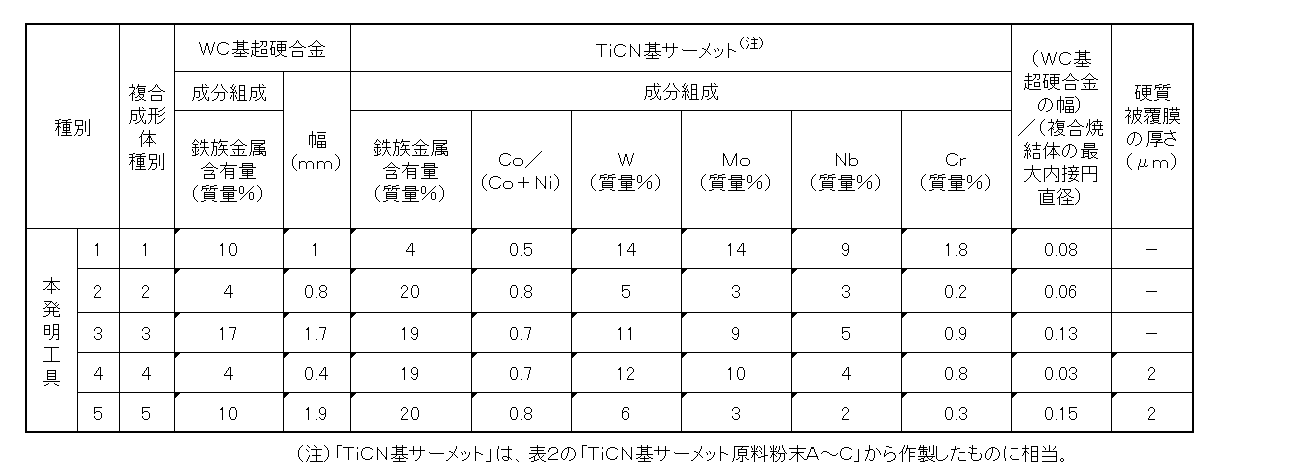


つぎに、上記本発明工具1~9および比較例工具1~9について、以下に記載する切削条件1及び切削条件2において、耐摩耗性及び耐異常損傷性について評価した。
[切削条件1]
被削材:JIS・SCM440の長さ方向4本溝入り丸棒、
切削速度:390 m/min.、
切り込み:0.3 mm、
送り:0.3 mm/rev.、
切削時間:10 分
の条件で、合金鋼の湿式高速断続加工試験(通常の切削速度は、200m/min.)を行い、逃げ面摩耗量、あるいは、寿命に至るまでの切削時間を測定した。
[切削条件2]
被削材:JIS・S45Cの長さ方向等間隔4本溝入丸棒
切削速度:320 m/min.、
切り込み: 2.0 mm、
送り: 0.2 mm/rev.,
切削時間:5 分
の条件で、炭素鋼の湿式断続切削加工試験を行い、耐異常損傷性を評価した。切れ刃にクラック、チッピング、欠損を生じた場合、異常損傷「有」とし、クラック、チッピング、欠損を生じない場合、異常損傷「無」とした。
さらに、本発明工具1~9および比較例工具1~6については、各工具においてサーメットと積層せず、全体をWC基超硬合金とした場合からの使用W量削減率(質量%)を算出した。
表8に、これらの結果を示す。
[切削条件1]
被削材:JIS・SCM440の長さ方向4本溝入り丸棒、
切削速度:390 m/min.、
切り込み:0.3 mm、
送り:0.3 mm/rev.、
切削時間:10 分
の条件で、合金鋼の湿式高速断続加工試験(通常の切削速度は、200m/min.)を行い、逃げ面摩耗量、あるいは、寿命に至るまでの切削時間を測定した。
[切削条件2]
被削材:JIS・S45Cの長さ方向等間隔4本溝入丸棒
切削速度:320 m/min.、
切り込み: 2.0 mm、
送り: 0.2 mm/rev.,
切削時間:5 分
の条件で、炭素鋼の湿式断続切削加工試験を行い、耐異常損傷性を評価した。切れ刃にクラック、チッピング、欠損を生じた場合、異常損傷「有」とし、クラック、チッピング、欠損を生じない場合、異常損傷「無」とした。
さらに、本発明工具1~9および比較例工具1~6については、各工具においてサーメットと積層せず、全体をWC基超硬合金とした場合からの使用W量削減率(質量%)を算出した。
表8に、これらの結果を示す。

表5~8に示される結果から、本発明工具は、タングステンの使用量を低減したとしても、TiCN基サーメット層とWC基超硬合金層の成分組成範囲を適正化するとともに、切れ刃を含む外周部を構成するWC基超硬合金層の幅の比率を適正化することによって、耐熱亀裂性を低下させることなく、切れ刃に断続的・衝撃的な高負荷が作用し、熱的負荷も作用する合金鋼等の湿式断続切削において、クラックの伝播・進展が抑制され、長期の使用に亘って、すぐれた耐異常損傷性、耐摩耗性を発揮し、WC基超硬合金のみから作製した比較例工具7(即ち、使用W量削減率はゼロ%の工具)に劣らない切削性能を示す。
さらに、耐異常損傷性の観点から見れば、本発明工具1~9は比較例工具7~9と比較して、優れた耐異常損傷性を有している。
これに対して、比較例工具1~6は、タングステン使用量は削減されているものの、耐熱亀裂性が劣るものであって、短時間で使用寿命に至ることは明らかである。
さらに、耐異常損傷性の観点から見れば、本発明工具1~9は比較例工具7~9と比較して、優れた耐異常損傷性を有している。
これに対して、比較例工具1~6は、タングステン使用量は削減されているものの、耐熱亀裂性が劣るものであって、短時間で使用寿命に至ることは明らかである。
図3あるいは図4に示す構造の複合焼結体切削工具(即ち、すくい面の平面形状が多角形であり、すくい面と逃げ面のなす角度が90度である、所謂ネガティブインサート)を以下の工程で作製した。
表1に示す配合組成の平均粒径0.5~3μmのWC基超硬合金原料粉末を用意する。
また、表2に示す配合組成の平均粒径0.5~3μmのTiCN基サーメット原料粉末を用意する。
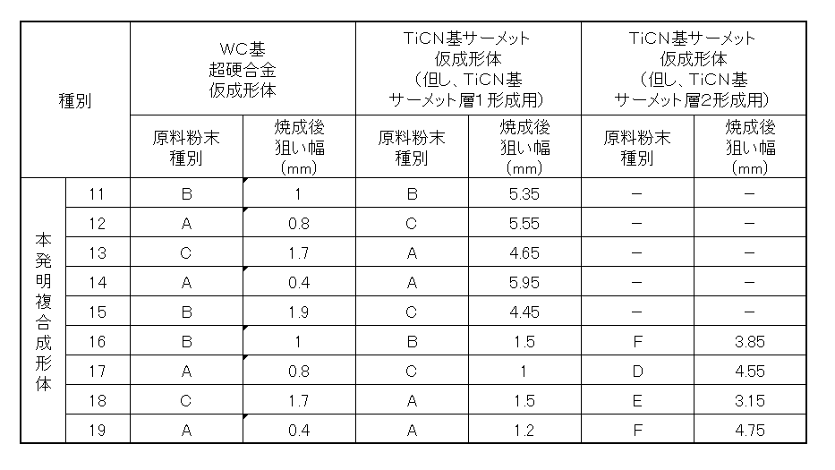
まず、上記WC基超硬合金原料粉末をISOインサート形状SNMN120408の素材用金型および内周部に空隙を設けるための入れ子を用いプレスして、表9に示す仮成形体11~19を作製した。
次に、上記仮成形体11~19の内周に、TiCN基サーメット原料粉末を配置し、上記仮成形体11~19とともに、ISOインサート形状SNMN120408の素材用金型でプレスし、複合成形体11~19を作製した。
上記仮成形体のうち、仮成形体16~19については、複数種類のTiCN基サーメット原料粉末を用い、それぞれのTiCN基サーメット原料粉末の中心位置がほぼ同位置になるように充填して、表9に示す仮成形体を作製した。
なお、作製した複合成形体11~19は、WC基超硬合金原料粉末と一種類のTiCN基サーメット原料粉末からなる複合成形体11~15と、WC基超硬合金原料粉末とTiCN基サーメット層1用原料粉末とTiCN基サーメット層2用原料粉末の二種類のTiCN基サーメット原料粉末を用いた複合成形体16~19である。
表1に示す配合組成の平均粒径0.5~3μmのWC基超硬合金原料粉末を用意する。
また、表2に示す配合組成の平均粒径0.5~3μmのTiCN基サーメット原料粉末を用意する。
まず、上記WC基超硬合金原料粉末をISOインサート形状SNMN120408の素材用金型および内周部に空隙を設けるための入れ子を用いプレスして、表9に示す仮成形体11~19を作製した。
次に、上記仮成形体11~19の内周に、TiCN基サーメット原料粉末を配置し、上記仮成形体11~19とともに、ISOインサート形状SNMN120408の素材用金型でプレスし、複合成形体11~19を作製した。
上記仮成形体のうち、仮成形体16~19については、複数種類のTiCN基サーメット原料粉末を用い、それぞれのTiCN基サーメット原料粉末の中心位置がほぼ同位置になるように充填して、表9に示す仮成形体を作製した。
なお、作製した複合成形体11~19は、WC基超硬合金原料粉末と一種類のTiCN基サーメット原料粉末からなる複合成形体11~15と、WC基超硬合金原料粉末とTiCN基サーメット層1用原料粉末とTiCN基サーメット層2用原料粉末の二種類のTiCN基サーメット原料粉末を用いた複合成形体16~19である。
ついで、この複合成形体11~19を、実施例1と同様な条件で焼結し、複合焼結体11~19を作製し、実施例1と同様なホーニング加工を施すことにより、表11、表12に示すSNMN120408形状の複合焼結体切削工具11~19(以下、本発明工具11~19という)を作製した。
ついで、上記本発明工具11~19について、実施例1と同様な方法で、WC基超硬合金層とTiCN基サーメット層あるいはTiCN基サーメット層1、TiCN基サーメット層2の成分組成を求めた。
さらに、WC基超硬合金層とTiCN基サーメット層の幅、また、TiCN基サーメット層1、TiCN基サーメット層2の幅を光学顕微鏡で観察して測定し、異なる5点において測定された幅を平均して平均幅とした。
表11、表12に、これらの値を示す。
さらに、WC基超硬合金層とTiCN基サーメット層の幅、また、TiCN基サーメット層1、TiCN基サーメット層2の幅を光学顕微鏡で観察して測定し、異なる5点において測定された幅を平均して平均幅とした。
表11、表12に、これらの値を示す。
ついで、本発明工具14,15,18,19については、WC基超硬合金層の表面に、アークイオンプレーティングにより、TiとAlの複合窒化物(なお、TiとAlの含有量は、それぞれ50原子%)からなる硬質被覆膜を蒸着形成した。
表10に、蒸着形成した硬質被覆膜の膜厚を示す。
表10に、蒸着形成した硬質被覆膜の膜厚を示す。
比較のため、表1に示す配合組成のWC基超硬合金原料粉末および表2に示す配合組成のTiCN基サーメット原料粉末を、実施例1と同様の方法で、表10に示す組合せで仮成形体11~16を作製し、更に、これをプレスすることにより、比較例複合成形体11~16を作製した後、この複合成形体を、実施例1と同じ条件で焼結して比較例複合焼結体11~16を作製した。
また、TiCN基サーメット原料粉末を使用することなく表1に示す配合組成のWC基超硬合金原料粉末のみから、WC基超硬合金のみからなる比較例焼結体17~19を作製した。
ついで、実施例1と同じ条件でホーニング加工を施すことにより、表13に示すSNMN120408形状の複合焼結体切削工具11~19(以下、比較例工具11~19という)を作製した。
また、TiCN基サーメット原料粉末を使用することなく表1に示す配合組成のWC基超硬合金原料粉末のみから、WC基超硬合金のみからなる比較例焼結体17~19を作製した。
ついで、実施例1と同じ条件でホーニング加工を施すことにより、表13に示すSNMN120408形状の複合焼結体切削工具11~19(以下、比較例工具11~19という)を作製した。
ついで、上記比較例工具11~16について、実施例1と同様な方法で、WC基超硬合金層とTiCN基サーメット層の成分組成を求めた。
また、WC基超硬合金層とTiCN基サーメット層の幅も求めた。
表13に、これらの値を示す。
また、WC基超硬合金層とTiCN基サーメット層の幅も求めた。
表13に、これらの値を示す。
ついで、比較例工具14,15については、WC基超硬合金層の表面に、アークイオンプレーティングにより、TiとAlの複合窒化物(なお、TiとAlの含有量は、それぞれ50原子%)からなる硬質被覆膜を蒸着形成した。
表13に、蒸着形成した硬質被覆膜の膜厚を示す。
表13に、蒸着形成した硬質被覆膜の膜厚を示す。
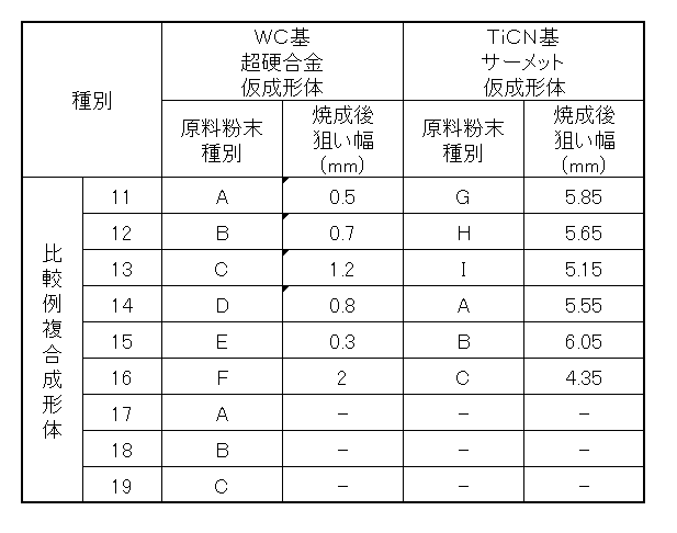


つぎに、上記本発明工具11~19および比較例工具11~19について、実施例1と同一の条件で、合金鋼の湿式断続切削加工試験を行い、逃げ面摩耗量を測定するとともに、炭素鋼の湿式断続切削加工試験を行い、耐異常損傷性を評価した。さらに、本発明工具11~19および比較例工具11~19について、各工具においてサーメットと積層せず、全体をWC基超硬合金とした場合からの使用W量削減率(質量%)を算出した。 表14に、これらの結果を示す。

表11~14に示される結果から、本発明工具は、タングステンの使用量を低減したとしても、TiCN基サーメット層とWC基超硬合金層の成分組成範囲を適正化するとともに、切れ刃を含む外周部を構成するWC基超硬合金層の厚さ比率を適正化することによって、耐熱亀裂性を低下させることなく、切れ刃に断続的・衝撃的な高負荷が作用し、熱的負荷も作用する合金鋼等の湿式断続切削において、クラックの伝播・進展が抑制され、長期の使用に亘って、すぐれた耐異常損傷性、耐摩耗性を発揮する。
これに対して、比較例工具11~16は、タングステン使用量は削減されているものの、耐熱亀裂性が劣るものであって、短時間で使用寿命に至っており、比較例工具17~19はタングステン使用量は削減されておらず、耐摩耗性に関しては本発明工具同等であるが、耐異常損傷性に関しては劣位であることは明らかである。
これに対して、比較例工具11~16は、タングステン使用量は削減されているものの、耐熱亀裂性が劣るものであって、短時間で使用寿命に至っており、比較例工具17~19はタングステン使用量は削減されておらず、耐摩耗性に関しては本発明工具同等であるが、耐異常損傷性に関しては劣位であることは明らかである。
次に、図5,図6に示す構造の複合焼結体切削工具(即ち、すくい面の平面形状が円形または多角形であり、すくい面と逃げ面のなす角度が90度未満である、所謂ポジティブインサート)を以下の手順で作製した。
表1に示す配合組成の平均粒径0.5~3μmのWC基超硬合金原料粉末を用意する。
また、表2に示す配合組成の平均粒径0.5~3μmのTiCN基サーメット原料粉末を用意する。
まず、上記WC基超硬合金原料粉末を、ISOインサート形状RGEN2004M0ENの素材用金型および内周部に空隙を設けるための入れ子を用いプレスして、表15に示す仮成形体21~25を作製した。
次に、上記仮成形体21~25の内周に、TiCN基サーメット原料粉末を配置し、上記仮成形体21~25とともに、ISOインサート形状RGEN2004M0ENの素材用金型でプレスし、複合成形体21~25を作製した。
表1に示す配合組成の平均粒径0.5~3μmのWC基超硬合金原料粉末を用意する。
また、表2に示す配合組成の平均粒径0.5~3μmのTiCN基サーメット原料粉末を用意する。
まず、上記WC基超硬合金原料粉末を、ISOインサート形状RGEN2004M0ENの素材用金型および内周部に空隙を設けるための入れ子を用いプレスして、表15に示す仮成形体21~25を作製した。
次に、上記仮成形体21~25の内周に、TiCN基サーメット原料粉末を配置し、上記仮成形体21~25とともに、ISOインサート形状RGEN2004M0ENの素材用金型でプレスし、複合成形体21~25を作製した。
また、上記WC基超硬合金粉末を、ISOインサート形状SEEN1203AFEN1の素材用金型および内周部に空隙を設けるための入れ子を用いプレスして、表15に示す仮成形体26~30を作製した。
次に、上記仮成形体26~30の内周に、TiCN基サーメット原料粉末を配置し、上記仮成形体26~30とともに、ISOインサート形状SEEN1203AFEN1の素材用金型でプレスし、複合成形体26~30を作製した。
次に、上記仮成形体26~30の内周に、TiCN基サーメット原料粉末を配置し、上記仮成形体26~30とともに、ISOインサート形状SEEN1203AFEN1の素材用金型でプレスし、複合成形体26~30を作製した。
ついで、この複合成形体21~30を、実施例1と同様な条件で焼結して複合焼結体21~30を作製し、WC基超硬合金からなる切れ刃を含む外周部について、R=0.04のホーニング加工を施して刃先を形成し、表16に示すRGEN2004M0EN形状の複合焼結体切削工具21~25(以下、本発明工具21~25という)及びSEEN1203AFEN1形状の複合焼結体切削工具26~30(以下、本発明工具26~30という)作製した。
ついで、上記本発明工具21~30について、実施例1と同様な方法で、WC基超硬合金層とTiCN基サーメット層の成分組成を求めた。
また、WC基超硬合金層とTiCN基サーメット層の最大厚さ、最小厚さを光学顕微鏡で観察して測定し、異なる5点において測定された幅を平均して平均幅とした。
表16に、これらの値を示す。
また、WC基超硬合金層とTiCN基サーメット層の最大厚さ、最小厚さを光学顕微鏡で観察して測定し、異なる5点において測定された幅を平均して平均幅とした。
表16に、これらの値を示す。
ついで、本発明工具24,25,29,30については、WC基超硬合金層の表面に、アークイオンプレーティングにより、TiとAlの複合窒化物(なお、TiとAlの含有量は、それぞれ50原子%)からなる硬質被覆膜を蒸着形成した。
表16に、蒸着形成した硬質被覆膜の膜厚を示す。
表16に、蒸着形成した硬質被覆膜の膜厚を示す。
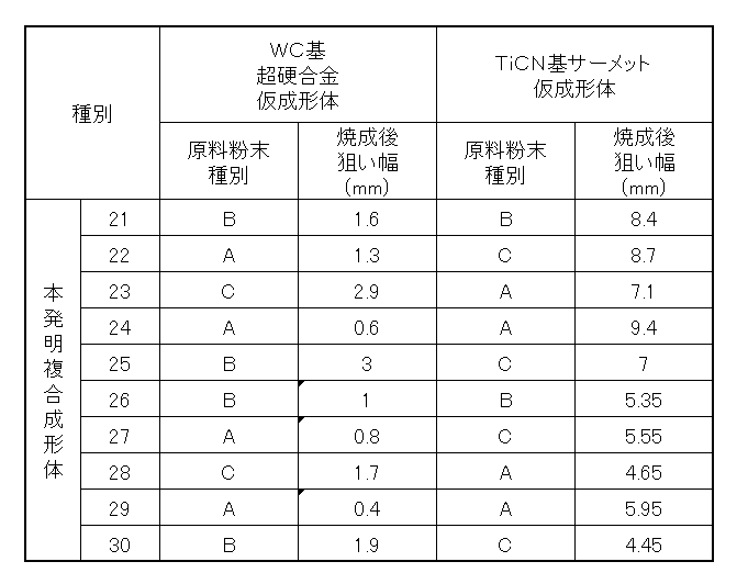

つぎに、上記本発明工具21~30について、カッタ径125mmの工具鋼製カッタ先端部に固定治具にてクランプした状態で、
[切削条件1]
被削材:JIS・SCr420の幅100mm、長さ400mmのブロック材、
切削速度:250m/min.、
切り込み:0.12mm、
送り:0.1mm/rev.、
切削時間:10分
の条件で、合金鋼の湿式フライス切削試験を行い、逃げ面摩耗量を測定した。
[切削条件2]
被削材:JIS・SCr440の幅100mm、長さ400mmのブロック材、
切削速度:315m/min.、
切り込み:0.11mm、
送り:0.1mm/rev.、
切削時間:5分
の条件で、合金鋼の湿式フライス切削試験を行い、異常損傷の有無を確認した。
さらに、本発明工具21~30について、各工具においてサーメットと積層せず、全体をWC基超硬合金とした場合からの使用W量削減率(質量%)を算出した。
表17に、これらの結果を示す。
[切削条件1]
被削材:JIS・SCr420の幅100mm、長さ400mmのブロック材、
切削速度:250m/min.、
切り込み:0.12mm、
送り:0.1mm/rev.、
切削時間:10分
の条件で、合金鋼の湿式フライス切削試験を行い、逃げ面摩耗量を測定した。
[切削条件2]
被削材:JIS・SCr440の幅100mm、長さ400mmのブロック材、
切削速度:315m/min.、
切り込み:0.11mm、
送り:0.1mm/rev.、
切削時間:5分
の条件で、合金鋼の湿式フライス切削試験を行い、異常損傷の有無を確認した。
さらに、本発明工具21~30について、各工具においてサーメットと積層せず、全体をWC基超硬合金とした場合からの使用W量削減率(質量%)を算出した。
表17に、これらの結果を示す。

表17に示される結果からも、本発明工具は、タングステンの使用量を低減したとしても、TiCN基サーメット層とWC基超硬合金層の成分組成範囲を適正化するとともに、切れ刃を含む外周部を構成するWC基超硬合金層の厚さ比率を適正化することによって、耐熱亀裂性を低下させることなく、切れ刃に断続的・衝撃的な高負荷が作用し、熱的負荷も作用する合金鋼等の湿式断続切削において、クラックの伝播・進展が抑制され、長期の使用に亘って、すぐれた耐異常損傷性、耐摩耗性を発揮することがわかる。
複合焼結体を工具基体とする本発明の切削工具は、希少金属であるタングステン使用量の低減を図り得るとともに、切れ刃に断続的・衝撃的な高負荷、熱的負荷が作用する湿式断続切削に用いた場合でも、耐熱亀裂性に優れ、チッピング、欠損、剥離等の異常損傷を発生することなく、長期の使用にわたってすぐれた切削性能を発揮することができ、切削加工の省エネ化、低コスト化に十分満足に対応できるものである。
Claims (2)
- TiCN基サーメット層とWC基超硬合金層との複合焼結体からなる切削工具において、
(a)上記切削工具は、すくい面の平面形状が円形または多角形であり、すくい面と逃げ面のなす角度は90度または90度未満であり、
(b)上記切削工具の切れ刃を含む外周部は、鉄族金属成分を4~17質量%、残部はWCを主たる硬質相成分とするWC基超硬合金層で構成され、また、外周部に囲繞された内部はTiCN基サーメット層で構成され、
(c)上記WC基超硬合金層からなる外周部の幅は、上記複合焼結体におけるすくい面の最大内接円直径の0.03~0.15倍であり、
(d)上記WC基超硬合金層からなる外周部で囲繞された内部のTiCN基サーメット層は、少なくとも1層以上のTiCN基サーメット層から構成され、WC基超硬合金層と隣接するTiCN基サーメット層は、該サーメットの構成成分の含有割合を金属成分の含有割合で表現した場合、少なくとも鉄族金属成分を4~25質量%、Wを15質量%未満、Moを2~15質量%、Nbを2~10質量%、Crを0.2~2質量%を含有し、かつ、鉄族金属成分であるCoとNiについて、CoとNiの合計含有量に対するCo含有割合は0.5~0.8(但し、質量比)を満足することを特徴とする複合焼結体切削工具。 - 前記TiCN基サーメット層とWC基超硬合金層とからなる複合焼結体の少なくともWC基超硬合金層の表面に、硬質被覆膜が形成されていることを特徴とする請求項1に記載の表面被覆複合焼結体切削工具。
Applications Claiming Priority (4)
| Application Number | Priority Date | Filing Date | Title |
|---|---|---|---|
| JP2015108977 | 2015-05-28 | ||
| JP2015-108977 | 2015-05-28 | ||
| JP2016-101838 | 2016-05-20 | ||
| JP2016101838A JP6745059B2 (ja) | 2015-05-28 | 2016-05-20 | 複合焼結体切削工具 |
Publications (1)
| Publication Number | Publication Date |
|---|---|
| WO2016190330A1 true WO2016190330A1 (ja) | 2016-12-01 |
Family
ID=57392801
Family Applications (1)
| Application Number | Title | Priority Date | Filing Date |
|---|---|---|---|
| PCT/JP2016/065394 Ceased WO2016190330A1 (ja) | 2015-05-28 | 2016-05-25 | 複合焼結体切削工具 |
Country Status (1)
| Country | Link |
|---|---|
| WO (1) | WO2016190330A1 (ja) |
Cited By (1)
| Publication number | Priority date | Publication date | Assignee | Title |
|---|---|---|---|---|
| CN108441664A (zh) * | 2018-05-22 | 2018-08-24 | 湘潭大学 | 超高强度可涂层TiCN基含钴钢结硬质合金及制备方法 |
Citations (3)
| Publication number | Priority date | Publication date | Assignee | Title |
|---|---|---|---|---|
| JP2011045954A (ja) * | 2009-08-27 | 2011-03-10 | Kyocera Corp | サーメット焼結体および切削工具 |
| JP5413047B2 (ja) * | 2009-08-17 | 2014-02-12 | 住友電気工業株式会社 | 複合焼結体 |
| JP2014172157A (ja) * | 2013-03-12 | 2014-09-22 | Mitsubishi Materials Corp | 表面被覆切削工具 |
-
2016
- 2016-05-25 WO PCT/JP2016/065394 patent/WO2016190330A1/ja not_active Ceased
Patent Citations (3)
| Publication number | Priority date | Publication date | Assignee | Title |
|---|---|---|---|---|
| JP5413047B2 (ja) * | 2009-08-17 | 2014-02-12 | 住友電気工業株式会社 | 複合焼結体 |
| JP2011045954A (ja) * | 2009-08-27 | 2011-03-10 | Kyocera Corp | サーメット焼結体および切削工具 |
| JP2014172157A (ja) * | 2013-03-12 | 2014-09-22 | Mitsubishi Materials Corp | 表面被覆切削工具 |
Cited By (2)
| Publication number | Priority date | Publication date | Assignee | Title |
|---|---|---|---|---|
| CN108441664A (zh) * | 2018-05-22 | 2018-08-24 | 湘潭大学 | 超高强度可涂层TiCN基含钴钢结硬质合金及制备方法 |
| CN108441664B (zh) * | 2018-05-22 | 2020-06-30 | 湘潭大学 | 超高强度可涂层TiCN基含钴钢结硬质合金及制备方法 |
Similar Documents
| Publication | Publication Date | Title |
|---|---|---|
| JP6614491B2 (ja) | 複合焼結体切削工具および表面被覆複合焼結体切削工具 | |
| JP5999362B2 (ja) | 表面被覆切削工具 | |
| EP3456867A1 (en) | Coated drill | |
| JP6853451B2 (ja) | 複合焼結体切削工具 | |
| JP2020132972A (ja) | 超硬合金および切削工具 | |
| JP6315197B2 (ja) | 複合焼結体切削工具 | |
| JP6745059B2 (ja) | 複合焼結体切削工具 | |
| JP6052502B2 (ja) | 表面被覆超硬合金製切削工具 | |
| JP2017007062A (ja) | 複合焼結体切削工具および表面被覆複合焼結体切削工具 | |
| JP2019155570A (ja) | 硬質被覆層が優れた耐酸化性・耐溶着性を発揮する表面被覆切削工具 | |
| WO2016190330A1 (ja) | 複合焼結体切削工具 | |
| JP5561607B2 (ja) | 表面被覆wc基超硬合金製インサート | |
| JP2008302439A (ja) | 表面被覆立方晶窒化ほう素基超高圧焼結材料製切削工具 | |
| KR102395885B1 (ko) | 절삭공구용 경질피막 | |
| JP5613888B2 (ja) | 表面被覆wc基超硬合金製インサート | |
| JP5517100B2 (ja) | 表面被覆wc基超硬合金製インサート | |
| WO2016104620A1 (ja) | 複合焼結体切削工具および表面被覆複合焼結体切削工具 | |
| JP2011195846A (ja) | 表面被覆wc基超硬合金製切削工具 | |
| JP2012143829A (ja) | 表面被覆wc基超硬合金製切削工具 | |
| JP2019155569A (ja) | 硬質被覆層が優れた耐酸化性・耐溶着性を発揮する表面被覆切削工具 | |
| JP2011051033A (ja) | 表面被覆切削工具 | |
| JP2008302438A (ja) | 表面被覆立方晶窒化ほう素基超高圧焼結材料製切削工具 | |
| JP2011177801A (ja) | 表面被覆wc基超硬合金製インサート | |
| JP5402521B2 (ja) | 表面被覆立方晶窒化ほう素基超高圧焼結材料製切削工具 | |
| JP2012096302A (ja) | 耐チッピング性にすぐれた表面被覆切削工具 |
Legal Events
| Date | Code | Title | Description |
|---|---|---|---|
| 121 | Ep: the epo has been informed by wipo that ep was designated in this application |
Ref document number: 16800034 Country of ref document: EP Kind code of ref document: A1 |
|
| NENP | Non-entry into the national phase |
Ref country code: DE |
|
| 122 | Ep: pct application non-entry in european phase |
Ref document number: 16800034 Country of ref document: EP Kind code of ref document: A1 |