WO2016190305A1 - 操舵反力装置及び操舵反力付与方法 - Google Patents
操舵反力装置及び操舵反力付与方法 Download PDFInfo
- Publication number
- WO2016190305A1 WO2016190305A1 PCT/JP2016/065313 JP2016065313W WO2016190305A1 WO 2016190305 A1 WO2016190305 A1 WO 2016190305A1 JP 2016065313 W JP2016065313 W JP 2016065313W WO 2016190305 A1 WO2016190305 A1 WO 2016190305A1
- Authority
- WO
- WIPO (PCT)
- Prior art keywords
- steering
- reaction force
- gear
- driving force
- large gear
- Prior art date
- Legal status (The legal status is an assumption and is not a legal conclusion. Google has not performed a legal analysis and makes no representation as to the accuracy of the status listed.)
- Ceased
Links
Images




Classifications
-
- B—PERFORMING OPERATIONS; TRANSPORTING
- B62—LAND VEHICLES FOR TRAVELLING OTHERWISE THAN ON RAILS
- B62D—MOTOR VEHICLES; TRAILERS
- B62D5/00—Power-assisted or power-driven steering
- B62D5/04—Power-assisted or power-driven steering electrical, e.g. using an electric servo-motor connected to, or forming part of, the steering gear
-
- B—PERFORMING OPERATIONS; TRANSPORTING
- B62—LAND VEHICLES FOR TRAVELLING OTHERWISE THAN ON RAILS
- B62D—MOTOR VEHICLES; TRAILERS
- B62D6/00—Arrangements for automatically controlling steering depending on driving conditions sensed and responded to, e.g. control circuits
-
- F—MECHANICAL ENGINEERING; LIGHTING; HEATING; WEAPONS; BLASTING
- F16—ENGINEERING ELEMENTS AND UNITS; GENERAL MEASURES FOR PRODUCING AND MAINTAINING EFFECTIVE FUNCTIONING OF MACHINES OR INSTALLATIONS; THERMAL INSULATION IN GENERAL
- F16H—GEARING
- F16H1/00—Toothed gearings for conveying rotary motion
- F16H1/02—Toothed gearings for conveying rotary motion without gears having orbital motion
- F16H1/04—Toothed gearings for conveying rotary motion without gears having orbital motion involving only two intermeshing members
- F16H1/12—Toothed gearings for conveying rotary motion without gears having orbital motion involving only two intermeshing members with non-parallel axes
- F16H1/16—Toothed gearings for conveying rotary motion without gears having orbital motion involving only two intermeshing members with non-parallel axes comprising worm and worm-wheel
Definitions
- the present invention provides a steering reaction force device for applying a steering reaction force to a steering wheel in a configuration in which torque transmission between a steering wheel and a steered wheel is performed in a mechanically disconnected state as in the steer-by-wire system. And a steering reaction force application method.
- a transmission mechanism that performs torque transmission between the steering wheel and the steered wheel in a mechanically disconnected state may be employed.
- the steering reaction force from the steering mechanism (steering device) is not transmitted to the steering wheel.
- a steering reaction force device is provided on the steering shaft that rotates around the axis of the steering wheel in accordance with the rotation of the steering wheel, and a reaction force that is opposite to the steering direction of the steering wheel is applied to the steering wheel.
- a steering reaction force control device As a configuration for applying a steering reaction force to a steering wheel, for example, there is a steering reaction force control device shown in Patent Document 1 below.
- This control device detects the turning reaction force acting on the turning mechanism with a turning reaction force sensor, or estimates the turning reaction force using the control amount of the turning motor and the turning displacement amount.
- a steering reaction force is applied to the steering wheel in accordance with the steering reaction force.
- the electric power steering device shown in the following Patent Document 2 is for assisting the operation of the steering wheel and not for providing a reaction force.
- the structure provided in the state shifted mutually is adopted. In this way, by shifting the phase of each motor, the influence of cogging by each motor is offset and the steering feeling is improved.
- the electric power steering apparatus shown in the following Patent Document 3 is not for applying a reaction force, similar to the one according to Patent Document 2, but, like the reaction force apparatus, it is integrated with the steering shaft around the axis.
- a rotating large gear and a small gear meshing with the large gear are provided, and rotation of the small gear gives a rotational driving force to the large gear to assist the operation of the steering wheel.
- Motors are provided at both ends of the small gear.
- the motor is provided at both ends of the small gear, and the first housing for storing each motor and the small gear, the second housing for storing the large gear, and the first housing and the second housing are connected to the small gear.
- a coupling means for coupling at a position where the large gear meshes with each other, thereby eliminating the misalignment of the output shaft of the motor and the small gear, improving the weight balance, and improving the mountability to the vehicle. can do.
- the steering reaction force control device and the electric power steering device described in Patent Documents 1 and 2 require high-accuracy component design and assembly, which may increase manufacturing costs.
- the electric power steering apparatus described in Patent Document 3 includes an adjusting unit that adjusts the distance between the rotation centers of the small gear and the large gear, and can appropriately adjust the size of the play.
- an object of the present invention is to prevent the uncomfortable feeling of steering operation caused by backlash without increasing the accuracy of the mechanism that generates the steering reaction force and performing mechanical adjustment.
- a large gear that rotates around a shaft integrally with a steering shaft that rotates around the shaft as the steering wheel rotates around the shaft, meshes with the large gear, A first small gear that applies rotational driving force to the large gear, a first reaction force motor that drives the first small gear, a second small gear that meshes with the large gear and applies rotational driving force to the large gear, A steering reaction force device including a second reaction force motor that drives the second small gear is configured.
- the second small gear is in the same direction as the rotational driving force in the direction opposite to the rotational direction given to the large gear by the first small gear or the rotational direction. It is preferable that a rotational driving force having a magnitude different from the rotational driving force provided by the first small gear is applied.
- the first small gear and the second small gear give the large gear a rotational driving force in the opposite direction, so that the first small gear and the large gear, and the second small gear and the large gear are always free of gaps. Occurrence of rattling can be reliably prevented. Also, by making the rotational driving force by both small gears different even in the same direction, in addition to the effect of preventing backlash, it is possible to give rotational driving force to the large gear in cooperation with the motor. It is possible to reduce the size of the motor.
- first reaction force motor and the second reaction force motor are specialized in the opposite rotation directions to optimize the motor characteristics and control, thereby further improving the steering feeling by the driver.
- a large gear that rotates around the shaft integrally with the steering shaft that rotates with the rotation of the steering wheel about the axis, and a rotational driving force is applied to the large gear by driving the first reaction force motor.
- a first small gear and a second small gear that applies a rotational driving force to the large gear by driving a second reaction force motor, and the steering wheel is steered as the steering wheel rotates and the steering wheel rotates.
- the steering phase difference ⁇ which is the difference from the turning angle of the steered wheels, with respect to a predetermined phase difference ⁇ 1 , ⁇ 2 ( ⁇ 1 ⁇ 2 and ⁇ 1 , ⁇ 2 > 0)
- ⁇ 1 , ⁇ 2 ⁇ 1 ⁇ 2 and ⁇ 1 , ⁇ 2 > 0
- the first reaction force motor is driven to give a first driving force in one direction to the large gear, while the second reaction force motor is driven.
- the large gear has the first direction opposite to the one direction.
- the absolute value of the steering phase difference ⁇ is equal to or smaller than the phase difference ⁇ 1
- by applying a first driving force in the opposite direction from both the small gears to the large gear, between the first small gear and the large gear, and The backlash between the second small gear and the large gear can be prevented.
- the magnitude of the first driving force is made as small as possible within a range where rattling can be prevented so as not to affect the steering operation by the driver.
- a second driving force in one direction is applied from the first small gear to the large gear, thereby steering the steering shaft.
- a reaction force corresponding to the magnitude of the phase difference ⁇ can be applied.
- a rotational driving force having the same magnitude as the first driving force in the direction opposite to the second driving force from the second small gear to the large gear both the small gear and the large gear are in a state of being firmly engaged. The play between both gears is prevented. Note that, as described above, the magnitude of the first driving force is set as small as possible within a range in which rattling can be prevented. Therefore, the first driving force causes almost no reaction force due to the second driving force. Has no effect.
- the steering wheel the steering shaft that rotates about the axis as the steering wheel rotates about the axis, the large gear that rotates about the axis integrally with the steering shaft, and the large gear mesh with each other,
- a first small gear that applies rotational driving force to the large gear;
- a first reaction force motor that drives the first small gear;
- a second small gear that meshes with the large gear and applies rotational driving force to the large gear;
- a second reaction force motor that drives the second small gear.
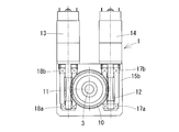
- a longitudinal sectional view showing an embodiment of a steering reaction force device according to the present invention 1 is a cross-sectional view of the steering reaction device shown in FIG.
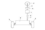
- Schematic showing the general arrangement of the steering reaction force device in the steering mechanism of the vehicle 1 is a cross-sectional view showing the operation of the steering reaction device shown in FIG. 1 when the absolute value ⁇ of the steering phase difference is equal to or smaller than the phase difference ⁇ 1 .
- 1 is a cross-sectional view showing the operation of the steering reaction force device shown in FIG. 1 when the steering phase difference ⁇ is larger than the phase difference ⁇ 1 and not more than the phase difference ⁇ 2 .
- the steering reaction device 1 includes a steering wheel 2, a first steering shaft 3 that rotates around the shaft together with the steering wheel 2, a torque sensor 4 that detects torque input to the steering wheel 2, and a pair A steering device 6 for steering the steered wheels 5, 5 (for example, left and right front wheels), a second steering shaft 7 for driving the steering device 6, and the first steering shaft 3 and the second steering shaft 7 are inserted.
- a steering shaft 3 of the steer-by-wire type steering mechanism provided with the clutch 8.
- the steered device 6 moves a steered shaft to the left and right via a rotation / linear motion conversion mechanism (not shown) by a motor (not shown) based on the steering angle of the steering wheel 2 to produce a pair of steered wheels. 5 and 5 are provided with a function of turning.
- the clutch 8 mechanically disconnects the connection between the first steering shaft 3 and the second steering shaft 7 in a normal state, and steers the pair of steered wheels 5 and 5 by a motor (not shown) by the steering device 6. While using the steer-by-wire system, the steering shafts 3 and 7 are mechanically connected in the event of an abnormality, and the rotation around the first steering shaft 3 associated with the operation of the steering wheel 2 is directly transmitted to the second steering shaft 7. Thus, it has a function of performing the minimum necessary steering even in this abnormal state.
- the steering reaction force device 1 is based on the turning amount of the steering device 6, the load from the pair of steered wheels 5, 5, the vehicle speed, the signal from the torque sensor 4, the steering angle, etc. in the disengaged state of the clutch 8.
- a steering reaction force is applied to the steering wheel 2.
- the steered device 6 steers the pair of steered wheels 5 and 5 based on a steering angle, a signal from the torque sensor 4 and the like.
- the steering reaction device 1 includes a large gear 10, a first small gear 11, a second small gear 12, a first reaction force motor 13, and a second reaction force.
- the motor 14 is a main component.
- the large gear 10 rotates around the axis integrally with the first steering shaft 3 that rotates around the axis as the steering wheel 2 rotates around the axis.
- a worm wheel is employed as the large gear 10
- a worm is employed as the first small gear 11 and the second small gear 12.
- Both the small gears 11 and 12 are provided at symmetrical positions around the large gear 10, and each mesh with the large gear 10.
- the first small gear 11 is driven by a first reaction force motor 13, and the second small gear 12 is driven by a second reaction force motor 14.
- the large gear 10 and the small gears 11 and 12 are accommodated in the housings 15a and 15b.
- bearings 16a and 16b are provided between the housings 15a and 15b and the first steering shaft 3.
- the first steering shaft 3 is rotatable relative to the housings 15a and 15b by the bearings 16a and 16b.
- Ball bearings rolling bearings
- the housings 15a and 15b are coupled with a bolt or the like (not shown).
- the combination of the worm wheel and the worm employed in this embodiment is merely an example, and other transmission mechanisms can be employed as long as the steering reaction force can be applied to the steering wheel 2.
- the two small gears 11 and 12 are arranged in parallel to each other. However, as long as the rotational driving forces in the opposite directions can be transmitted to the large gear 10, the two small gears 11 and 12. Can also be arranged non-parallel to each other. Both ends of the small gears 11 and 12 on the tip side and the motor side are rotatably supported in the housing 15b by rolling bearings 17a, 17b, 18a and 18b.
- the first reaction force motor 13 and the second reaction force motor 14 used in the steering reaction force device 1 can freely adjust their rotation direction and rotation speed. For example, when the large gear 10 that meshes with the first small gear 11 receives a rotational driving force from the first small gear 11, the rotational driving applied from the first small gear 11 to the large gear 10 from the second small gear 12. A rotational driving force in a direction opposite to the force can be applied.
- the first small gear 11 By setting the direction of the rotational driving force by the first small gear 11 to the large gear 10 and the direction of the rotational driving force by the second small gear 12 in opposite directions, one small gear (the first small gear 11 or the first small gear 11 or A steering reaction force can be applied to the steering wheel 2 via the large gear 10 by the rotational driving force of the second small gear 12), and the other small gear (the first small gear 11 or the second small gear 12)
- the play between the gear 10 and the small gears 11 and 12 can be prevented.
- the first reaction force motor 13 and the second reaction force motor 14 a synchronous motor, an induction motor, a DC motor, or the like can be employed.
- the first reaction force motor 13 and the second reaction force motor 14 can cooperate with each other to apply a rotational driving force to the large gear 10, thereby reducing the size of the individual motors 13, 14, It is possible to prevent overheating.
- the configuration in which the two small gears 11 and 12 mesh with the large gear 10 is illustrated, but at least one small gear that gives the large gear 10 a rotational driving force in one direction, and the large gear 10.
- at least one other small gear that gives a rotational driving force in a direction opposite to the one direction is provided, three or more small gears can be engaged with each other. This is because even in this configuration, the effect of preventing rattling between the large gear 10 and each small gear while exerting a steering reaction force on the steering wheel 2 is exhibited.
- FIG. 4A, 4B, 5 and 6 A steering reaction force applying method according to the present invention will be described with reference to FIGS. 4A, 4B, 5 and 6.
- FIG. 3 In this steering reaction force application method, a large gear 10 that rotates around the axis integrally with the first steering shaft 3 that rotates with rotation of the steering wheel 2 (see FIG. 3), and a first reaction force motor.
- a first small gear 11 that gives rotational driving force to the large gear 10 by driving 13
- a second small gear 12 that gives rotational driving force to the large gear 10 by driving the second reaction force motor 14.
- the steering phase difference ⁇ which is the difference between the rotation angle of the steering wheel 2 and the turning angle of the pair of steered wheels 5, 5 (see FIG. 3) steered with the rotation of the steering wheel 2, is determined in advance.
- the first small gear 11 and the second small gear according to the magnitude relationship with the phase differences ⁇ 1 , ⁇ 2 , ⁇ 3 ( ⁇ 1 ⁇ 2 ⁇ 3 and ⁇ 1 , ⁇ 2 , ⁇ 3 > 0).
- phase difference ⁇ When the absolute value of the steering phase difference ⁇ is equal to or smaller than the phase difference ⁇ 1 (when the phase difference is in the range of ⁇ 1 to ⁇ 1 , see the region indicated by A in FIG. 5), the steering reaction force T 1 and T 2 , a reverse first driving force (see FIG. 4A) is applied from both the small gears 11 and 12 to the large gear 10.
- the magnitude of the first driving force is made as small as possible within a range in which rattling can be prevented while not affecting the steering operation by the driver.
- one small gear (for example, the first small gear) is used as the steering reaction force T 1.
- the large gear 10 in one direction (the direction opposite to the operation direction of the steering wheel 2 (see arrow r in FIG. 4B)) that is larger than the first driving force and increases as the steering phase difference ⁇ increases.
- a reaction force corresponding to the magnitude of the steering phase difference ⁇ can be applied to the first steering shaft 3, and a self-aligning function for returning the steering wheel 2 to the neutral state is exhibited.
- the other pinion e.g., the second pinion 12
- the rotational driving force of the same magnitude as the first driving force of the and the second driving force reverse
- both the small gears 11 and 12 and the large gear 10 are brought into a state of being firmly engaged with each other, and play between the gears 10, 11, and 12 is prevented (see FIG. 4B).
- the magnitude of the first driving force is set as small as possible within a range in which rattling can be prevented. Therefore, the first driving force causes almost no reaction force due to the second driving force. Has no effect.
- the steering phase difference ⁇ is larger than the phase difference ⁇ 2 and equal to or smaller than the phase difference ⁇ 3 (see the region indicated by C in FIG. 5)
- one of the small gears gives the large gear 10 a third driving force in one direction that is larger than the second driving force and increases as the steering phase difference ⁇ increases, and the other small gear (for example, the second small gear 11).
- a fourth driving force in one direction which is larger than the first driving force, increases as the steering phase difference ⁇ increases, and is smaller than the third driving force, is applied to the large gear 10 from the gear 12).
- one small gear for example, the first small gear 11
- the steering reaction forces T 1 and T 2 are used as the steering reaction forces T 1 and T 2.
- the other small gear for example, the second small gear 12
- the large gear 10 while giving a fifth driving force in one direction larger than the third driving force and increasing as the steering phase difference ⁇ increases. 10
- the sixth driving force in the one direction having the same constant magnitude as the maximum value of the fourth driving force is applied.
- the above-described embodiment is merely an example, and it is an object of the present invention to prevent an uncomfortable feeling of steering operation due to backlash without performing high-precision and mechanical adjustment of a mechanism that generates a steering reaction force.
- the configuration, arrangement, and number of the large gears 10 and the small gears 11 and 12 and the direction and magnitude of the rotational driving force applied from the small gears 11 and 12 to the large gear 10 are appropriately changed. Is acceptable.
Landscapes
- Engineering & Computer Science (AREA)
- Chemical & Material Sciences (AREA)
- Combustion & Propulsion (AREA)
- Transportation (AREA)
- Mechanical Engineering (AREA)
- Power Steering Mechanism (AREA)
- Steering Control In Accordance With Driving Conditions (AREA)
- Gear Transmission (AREA)
Abstract
大歯車(10)に噛み合い、大歯車(10)に回転駆動力を与える第一小歯車(11)と、第一小歯車(11)を駆動する第一反力モータ(13)と、大歯車(10)に噛み合い、大歯車(10)に回転駆動力を与える第二小歯車(12)と、第二小歯車(12)を駆動する第二反力モータ(14)とを備えた操舵反力装置(1)であり、一つの大歯車(10)に第一小歯車(11)と第二小歯車(12)がともに噛み合う構成とすることによって、そのガタを防止することができ、各歯車(10、11、12)の部品設計及びアセンブリの高精度化や、機械的調整が不要となるとともに、自然なステアリング操作を行うことができる。
Description
この発明は、ステアリングホイールと転舵輪との間のトルク伝達を、ステアバイワイヤ方式のように機械的に非連結の状態で行う構成において、このステアリングホイールに操舵反力を与えるための操舵反力装置及び操舵反力付与方法に関する。
ステアバイワイヤ方式のように、ステアリングホイールと転舵輪との間のトルク伝達を、機械的に非連結とした状態で行う伝達機構が採用されることがある。この構成においては、転舵機構(ステアリング装置)からの転舵反力がステアリングホイールに伝達されない。このため、ステアリングホイールの軸周りの回転に伴って軸周りに回転する操舵軸に操舵反力装置を設け、ステアリングホイールの操舵方向とは逆方向の反力をこのステアリングホイールに付与し、運転者に自然なステアリング操作感を与えるようにしている。
ステアリングホイールに操舵反力を付与する構成として、例えば、下記特許文献1に示す操舵反力制御装置がある。この制御装置は、転舵機構に作用する転舵反力を転舵反力センサで検出し、あるいは、転舵モータの制御量及び転舵変位量を用いて転舵反力を推定し、この転舵反力に応じて、ステアリングホイールに操舵反力を付与している。
下記特許文献2に示す電動パワーステアリング装置は、ステアリングホイールの操作をアシストするためのものであって、反力を付与するためのものではないが、操舵機構に複数のモータを、それぞれの位相を相互にずらした状態で設けた構成を採用している。このように、各モータの位相をずらすことで、各モータによるコギングの影響を相殺し、操舵感覚の向上を図っている。
下記特許文献3に示す電動式パワーステアリング装置は、特許文献2に係るものと同様に、反力を付与するためのものではないが、反力装置と同様に、操舵軸と一体に軸周りに回転する大歯車と、この大歯車と噛み合う小歯車とを備え、この小歯車の回転によって大歯車に回転駆動力を与えて、ステアリングホイールの操作をアシストしている。この小歯車の両端には、それぞれモータが設けられている。このように、小歯車の両端にモータを設け、各モータ及び前記小歯車を収納する第1ハウジングと、前記大歯車を収納する第2ハウジングと、前記第1ハウジング及び第2ハウジングを前記小歯車と大歯車とが噛合う位置で連結する連結手段とを備えることにより、モータの出力軸及び小歯車の芯ずれをなくすとともに、重量バランスを良好にでき、しかも、車両への搭載性を良好にすることができる。
特許文献1~3等に示す操舵反力制御装置や電動式パワーステアリング装置においては、操舵軸に設けられた歯車と、モータによって駆動され、前記歯車と噛み合う歯車との間の遊びが大きいと、バックラッシによってガタが生じ、ステアリング操作の際に運転者に違和感が生じたり、各歯車の偏心に起因する押し付け量の変動に伴って、回転のトルク変動を生じたりする一方で、完全にこの遊びをなくしてしまうと、動力伝達のスムーズ性が損なわれる問題がある。
この問題を解決するためには、特許文献1、2に記載の操舵反力制御装置、電動式パワーステアリング装置においては、高精度な部品設計とアセンブリが必要となり、製造コストが高くなる虞がある。また、特許文献3に記載の電動式パワーステアリング装置は、小歯車及び大歯車の回転中心間距離を調整する調整手段を備えており、ガタの大きさを適切に調整し得るようになっているものの、その調整は、ステアリング操作と調整手段の調整を繰り返し行って操作感を確認する必要があり、その調整に大きな手間を要する。
そこで、この発明は、操舵反力を発生させる機構の高精度化や機械的調整を行うことなく、ガタに起因するステアリング操作の違和感を防止することを課題とする。
上記の課題を解決するために、この発明においては、ステアリングホイールの軸周りの回転に伴って軸周りに回転する操舵軸と一体に軸周りに回転する大歯車と、前記大歯車に噛み合い、前記大歯車に回転駆動力を与える第一小歯車と、前記第一小歯車を駆動する第一反力モータと、前記大歯車に噛み合い、前記大歯車に回転駆動力を与える第二小歯車と、前記第二小歯車を駆動する第二反力モータと、を備えた操舵反力装置を構成した。
このように、一つの大歯車に第一小歯車と第二小歯車がともに噛み合う構成とすることによって、例えば、大歯車と両小歯車との間に遊びがあっても、第二小歯車から大歯車に回転駆動力を与えることによってその遊びに起因するガタを防止することができる。このため、各歯車の部品設計及びアセンブリの高精度化や、機械的調整が不要となって、製造コストを大幅に低減することができるとともに、動力伝達がスムーズになり、自然なステアリング操作を行うことができる。
前記構成においては、前記第二小歯車が、前記大歯車に、前記第一小歯車によって前記大歯車に与えられた回転方向とは逆方向の回転駆動力、又は、前記回転方向と同一方向であって前記第一小歯車によって与えられる回転駆動力と異なる大きさの回転駆動力を与える構成とするのが好ましい。
このように、第一小歯車と第二小歯車が、大歯車に逆方向の回転駆動力を与えることによって、第一小歯車と大歯車、及び、第二小歯車と大歯車が常に隙間なく噛み合った状態となって、ガタの発生を確実に防止することができる。また、同一方向であっても両小歯車による回転駆動力が異なるようにすることによって、ガタの防止効果に加えて、モータを協働して大歯車に回転駆動力を与えることができ、個々のモータの小型化を図ることができる。
また、第一反力モータ及び第二反力モータを、それぞれ逆の回転方向に特化させて、モータ特性や制御を最適化することにより、運転者による操舵感をさらに向上させることができる。
さらに、この発明においては、ステアリングホイールの軸周りの回転に伴って回転する操舵軸と一体に軸周りに回転する大歯車と、第一反力モータの駆動によって前記大歯車に回転駆動力を与える第一小歯車と、第二反力モータの駆動によって前記大歯車に回転駆動力を与える第二小歯車とを備え、前記ステアリングホイールの回転角と、ステアリングホイールの回転に伴って転舵された転舵輪の転舵角度との差である操舵位相差θが、予め決めた位相差θ1、θ2(θ1<θ2、かつ、θ1、θ2>0)に対し、前記操舵位相差θの絶対値が位相差θ1以下のときは、前記第一反力モータの駆動により、前記大歯車に一方向の第一駆動力を与える一方で、前記第二反力モータの駆動により、前記大歯車に、前記一方向とは逆方向の前記第一駆動力と同じ大きさの回転駆動力を与え、前記操舵位相差θの絶対値が位相差θ1より大きく位相差θ2以下のときは、前記第一反力モータの駆動により、前記大歯車に、前記第一駆動力より大きく、かつ、前記操舵位相差θの増大とともに増大する前記一方向の第二駆動力を与える一方で、前記第二反力モータの駆動により、前記大歯車に、前記一方向とは逆方向の前記第一駆動力と同じ大きさの回転駆動力を与え、前記操舵位相差θの絶対値が位相差θ2より大きいときは、前記第一反力モータの駆動により、前記大歯車に、前記第二駆動力より大きく、かつ、前記操舵位相差θの増大とともに増大する前記一方向の第三駆動力を与える一方で、前記第二反力モータの駆動により、前記大歯車に、前記第一駆動力より大きく、かつ、前記操舵位相差θの増大とともに増大する前記一方向の第四駆動力を与え、前記操舵軸に操舵反力を付与する操舵反力付与方法を構成した。
このように、操舵位相差θの大きさに対応して、第一小歯車及び第二小歯車から大歯車に与える回転駆動力の方向及び大きさを適宜変化させることによって、両小歯車と大歯車との間のガタを抑制しつつ、スムーズにステアリング操作を行うことができる。
すなわち、操舵位相差θの絶対値が位相差θ1以下のときに、両小歯車から大歯車に逆向きの第一駆動力を与えることにより、第一小歯車と大歯車との間、及び、第二小歯車と大歯車との間のガタを防止することができる。この第一駆動力の大きさは、運転者によるステアリング操作に影響を及ぼさないように、ガタを防止し得る範囲で極力小さくする。
また、操舵位相差θの絶対値が位相差θ1より大きく位相差θ2以下のときに、第一小歯車から大歯車に一方向の第二駆動力を与えることにより、操舵軸に、操舵位相差θの大きさに対応した反力を与えることができる。また、第二小歯車から大歯車に前記第二駆動力とは逆方向の第一駆動力と同じ大きさの回転駆動力を与えることにより、両小歯車と大歯車がしっかりと噛み合った状態となり、両歯車の間のガタが防止される。なお、上述したように、第一駆動力の大きさは、ガタを防止し得る範囲で極力小さく設定されているため、この第一駆動力によって、第二駆動力による反力の発生にはほとんど影響を及ぼさない。
さらに、操舵位相差θの絶対値が位相差θ2より大きいときに、第一小歯車から大歯車に一方向の第三駆動力を与えるとともに、第二小歯車から大歯車に前記一方向の第四駆動力を与えることにより、両小歯車の回転駆動力が協働して大歯車に伝達され、操舵位相差θが相対的に大きくなったときに、大きな反力を効率的に発生させることができる。しかも、複数のモータを協働させることにより、駆動力の不足やモータの過熱等の問題を回避することができるとともに、モータの小型化を図ることもできる。
この発明においては、ステアリングホイールと、前記ステアリングホイールの軸周りの回転に伴って軸周りに回転する操舵軸と、前記操舵軸と一体に軸周りに回転する大歯車と、前記大歯車に噛み合い、前記大歯車に回転駆動力を与える第一小歯車と、前記第一小歯車を駆動する第一反力モータと、前記大歯車に噛み合い、前記大歯車に回転駆動力を与える第二小歯車と、前記第二小歯車を駆動する第二反力モータと、を備えた操舵反力装置を構成した。
このように、一つの大歯車に第一小歯車と第二小歯車がともに噛み合う構成とすることによって、例えば、大歯車と両小歯車との間に若干の遊びがあったとしても、第二小歯車から大歯車に回転駆動力を与えることによってその遊びに起因するガタを防止することができる。このため、各歯車の部品設計及びアセンブリの高精度化や、機械的調整が不要となって、製造コストを大幅に低減することができるとともに、動力伝達がスムーズになり、自然なステアリング操作を行うことができる。
この発明に係る操舵反力装置1の実施形態を図1及び図2に示す。この操舵反力装置1は、図3に示すように、ステアリングホイール2、ステアリングホイール2とともに軸周りに回転する第一操舵軸3、ステアリングホイール2に入力されたトルクを検出するトルクセンサ4、一対の転舵輪5、5(例えば、左右の前輪)を転舵する転舵装置6、転舵装置6を駆動する第二操舵軸7、及び第一操舵軸3と第二操舵軸7が挿し込まれるクラッチ8を備えた、ステアバイワイヤ方式の転舵機構の第一操舵軸3に設けられる。
転舵装置6は、ステアリングホイール2の操舵角に基づいて、モータ(図示せず)で回転直動変換機構(図示せず)を介して転舵軸を左右に移動させて、一対の転舵輪5、5を転舵する機能を備えている。クラッチ8は、通常時には第一操舵軸3と第二操舵軸7との間の連結を機械的に切断して、転舵装置6により図示しないモータにより一対の転舵輪5、5を転舵するステアバイワイヤ方式にする一方で、異常時には両操舵軸3、7を機械的に連結して、ステアリングホイール2の操作に伴う第一操舵軸3の軸周りの回転を第二操舵軸7に直接伝達して、この異常時においても必要最小限の転舵を行う機能を備えている。
操舵反力装置1は、クラッチ8の切断状態において、転舵装置6の転舵量、一対の転舵輪5、5からの荷重、車速、トルクセンサ4からの信号、操舵角等に基づいて、ステアリングホイール2に操舵反力を与える。また、転舵装置6は、操舵角やトルクセンサ4からの信号等に基づいて一対の転舵輪5、5を転舵する。
この実施形態に係る操舵反力装置1は、図1及び図2に示すように、大歯車10、第一小歯車11、第二小歯車12、第一反力モータ13、及び第二反力モータ14を主要な構成要素としている。
大歯車10は、ステアリングホイール2の軸周りの回転に伴って軸周りに回転する第一操舵軸3と一体に軸周りに回転する。大歯車10として、ウォームホイールが、第一小歯車11及び第二小歯車12として、ウォームがそれぞれ採用されている。両小歯車11、12は大歯車10を中心とした対称の位置に設けられており、それぞれが大歯車10と噛み合っている。第一小歯車11は第一反力モータ13に、第二小歯車12は第二反力モータ14によって駆動される。
大歯車10及び両小歯車11、12は、ハウジング15a、15b内に収納されている。ハウジング15a、15bと第一操舵軸3との間には、軸受16a、16bが介在して設けられている。この軸受16a、16bによって、第一操舵軸3がハウジング15a、15bに対して相対回転可能となっている。この軸受16a、16bとして玉軸受(転がり軸受)が用いられており、滑らかな操舵感が確保されている。なお、ハウジング15a、15bは、図示しないボルト等で結合されている。
この実施形態で採用したウォームホイールとウォームの組み合わせは、あくまでも例示であって、ステアリングホイール2に操舵反力を与えることができる限りにおいて、他の伝達機構を採用することもできる。また、この実施形態においては、両小歯車11、12は互いに平行に配置されているが、大歯車10に対し、互いに逆向きの回転駆動力を伝達し得る限りにおいて、両小歯車11、12を互いに非平行に配置することもできる。両小歯車11、12の先端側とモータ側の両端は、転がり軸受17a、17b、18a、18bにより、ハウジング15b内で回転自在に支持されている。
この操舵反力装置1に用いられる第一反力モータ13、第二反力モータ14は、その回転方向及び回転速度を自在に調節し得るようになっている。例えば、第一小歯車11と噛み合う大歯車10が、この第一小歯車11から回転駆動力を受けるときには、第二小歯車12から大歯車10に対し、第一小歯車11から与えられる回転駆動力とは逆方向の回転駆動力が与えられるようにすることができる。このように、大歯車10に対する第一小歯車11による回転駆動力と、第二小歯車12による回転駆動力の向きを逆方向とすることにより、一方の小歯車(第一小歯車11又は第二小歯車12)の回転駆動力によって大歯車10を介してステアリングホイール2に操舵反力を与えることができるとともに、他方の小歯車(第一小歯車11又は第二小歯車12)で、大歯車10と両小歯車11、12との間のガタを防止することができる。第一反力モータ13及び第二反力モータ14として、同期モータ、誘導モータ、直流モータ等を採用することができる。
また、第二小歯車12から大歯車10に対し、第一小歯車11から与えられる回転駆動力と同一方向であって、異なる大きさの回転駆動力が与えられるようにすることもできる。このように、第一小歯車11から大歯車10に対する回転駆動力と、第二小歯車12から大歯車10に対する回転駆動力の向きを同一方向とすることにより、ガタの防止効果に加えて、第一反力モータ13及び第二反力モータ14を協働して大歯車10に回転駆動力を与えることができ、個々のモータ13、14の小型化や、駆動時におけるモータ13、14の過熱防止を図ることができる。
この実施形態においては、大歯車10に二個の小歯車11、12が噛み合う構成を例示したが、大歯車10に一方向への回転駆動力を与える少なくとも一個の小歯車と、この大歯車10に前記一方向とは逆方向への回転駆動力を与える少なくとも一個の他の小歯車を備える限りにおいて、三個以上の小歯車が噛み合う構成とすることもできる。この構成においても、ステアリングホイール2に操舵反力を与えつつ、大歯車10と各小歯車との間のガタを防止するという効果が発揮されるためである。
この発明に係る操舵反力付与方法を図4A,図4B、図5及び図6を用いて説明する。この操舵反力付与方法においては、ステアリングホイール2(図3参照)の軸周りの回転に伴って回転する第一操舵軸3と一体に軸周りに回転する大歯車10と、第一反力モータ13の駆動によって大歯車10に回転駆動力を与える第一小歯車11と、第二反力モータ14の駆動によって大歯車10に回転駆動力を与える第二小歯車12と、を備えた構成において、ステアリングホイール2の回転角と、ステアリングホイール2の回転に伴って転舵された一対の転舵輪5、5(図3参照)の転舵角度との差である操舵位相差θと、予め決めた位相差θ1、θ2、θ3(θ1<θ2<θ3、かつ、θ1、θ2、θ3>0)との大小関係に従って、第一小歯車11及び第二小歯車12による大歯車10への転舵反力(回転駆動力)の方向及び大きさを適宜変更する。
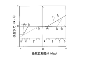
操舵位相差θの絶対値が、位相差θ1以下のとき(位相差が、-θ1~θ1の範囲内のとき。図5中にAで示す領域参照)には、操舵反力T1、T2として、両小歯車11、12から大歯車10に逆向きの第一駆動力(図4A参照)を与える。この位相差範囲は、ステアリングホイール2の中立位置(θ=0)を中心として、ステアリング操作を行っても実際には転舵されない、所謂ステアリングホイール2の「遊び」の範囲に相当する。
両小歯車11、12から大歯車10に、互いに逆向きの第一駆動力を与えることにより、第一小歯車11と大歯車10との間、及び、第二小歯車12と大歯車10との間のガタを防止することができる。この第一駆動力の大きさは、運転者によるステアリング操作に影響を及ぼさないようにしつつ、ガタを防止し得る範囲で極力小さくする。
操舵位相差θが、位相差θ1より大きく位相差θ2以下のとき(図5中にBで示す領域参照)には、操舵反力T1として、一方の小歯車(例えば、第一小歯車11)から大歯車10に、前記第一駆動力より大きく、操舵位相差θの増大とともに増大する一方向(ステアリングホイール2の操作方向(図4B中の矢印r参照)とは反対方向)の第二駆動力を与えることにより、第一操舵軸3に操舵位相差θの大きさに対応した反力を与えることができるとともに、ステアリングホイール2を中立状態に戻すセルフアライニング機能が発揮される。
また、操舵反力T2として、他方の小歯車(例えば、第二小歯車12)から大歯車10に、前記第二駆動力とは逆方向の第一駆動力と同じ大きさの回転駆動力を与えることにより、両小歯車11、12と大歯車10がしっかりと噛み合った状態となり、各歯車10、11、12の間のガタが防止される(図4B参照)。なお、上述したように、第一駆動力の大きさは、ガタを防止し得る範囲で極力小さく設定されているため、この第一駆動力によって、第二駆動力による反力の発生にはほとんど影響を及ぼさない。
操舵位相差θが、位相差θ2より大きく位相差θ3以下のとき(図5中にCで示す領域参照)には、操舵反力T1、T2として、一方の小歯車(例えば、第一小歯車11)から大歯車10に、前記第二駆動力より大きく、操舵位相差θの増大とともに増大する一方向の第三駆動力を与えるとともに、他方の小歯車(例えば、第二小歯車12)から大歯車10に、前記第一駆動力より大きく、操舵位相差θの増大とともに増大し、かつ前記第三駆動力よりも小さい、前記一方向の第四駆動力を与える。
これにより、両小歯車11、12の回転駆動力が協働して大歯車10に伝達され、操舵位相差θが相対的に大きくなったときに、大きな反力を効率的に発生させることができる。しかも、複数の反力モータ13、14を協働させることにより、駆動力の不足や反力モータ13、14の過熱等の問題を回避することができるとともに、反力モータ13、14の小型化を図ることもできる。
操舵位相差θが、位相差θ3より大きいとき(図5中にDで示す領域参照)には、操舵反力T1、T2として、一方の小歯車(例えば、第一小歯車11)から大歯車10に、前記第三駆動力より大きく、操舵位相差θの増大とともに増大する一方向の第五駆動力を与えるとともに、他方の小歯車(例えば、第二小歯車12)から大歯車10に、第四駆動力の最大値と同じ一定の大きさであって前記一方向の第六駆動力を与える。これにより、他方の反力モータ13、14の過負荷状態を防止しつつ、大きな反力を効率的に発生することができる。
上記においては、主に操舵位相差θが正の場合について説明したが、操舵位相差θが負の場合(図5中にB’、C’、D’で示す領域参照)には、第一小歯車11及び第二小歯車12の回転駆動の方向を逆向きにすることによって、上記と同様の作用を得ることができる。図5に示した第一小歯車11及び第二小歯車12によって与えられる操舵反力T1、T2を合成した操舵反力T(=T1-T2)を図6に示す。このように、操舵位相差θの大きさに対応して、第一小歯車11及び第二小歯車12の操舵反力を制御することにより、大歯車10と両小歯車11、12との間のガタの発生を防止しつつ、ステアリングホイール2に操舵反力を与えることができる。
なお、上記の実施形態はあくまでも一例であって、操舵反力を発生させる機構の高精度化や機械的調整を行うことなく、ガタに起因するステアリング操作の違和感を防止する、という本願発明の課題を解決し得る限りにおいて、大歯車10及び小歯車11、12の構成、配置、数や、各小歯車11、12から大歯車10に与えられる回転駆動力の向きや大きさを適宜変更することが許容される。
1 操舵反力装置
2 ステアリングホイール
3 第一操舵軸(操舵軸)
4 トルクセンサ
5 転舵輪
6 転舵装置
7 第二操舵軸
8 クラッチ
10 大歯車
11 第一小歯車
12 第二小歯車
13 第一反力モータ
14 第二反力モータ
15a、15b ハウジング
16a、16b 軸受
17a、17b、18a、18b 転がり軸受
2 ステアリングホイール
3 第一操舵軸(操舵軸)
4 トルクセンサ
5 転舵輪
6 転舵装置
7 第二操舵軸
8 クラッチ
10 大歯車
11 第一小歯車
12 第二小歯車
13 第一反力モータ
14 第二反力モータ
15a、15b ハウジング
16a、16b 軸受
17a、17b、18a、18b 転がり軸受
Claims (3)
- ステアリングホイール(2)の軸周りの回転に伴って軸周りに回転する操舵軸(3)と一体に軸周りに回転する大歯車(10)と、
前記大歯車(10)に噛み合い、前記大歯車(10)に回転駆動力を与える第一小歯車(11)と、
前記第一小歯車(11)を駆動する第一反力モータ(13)と、
前記大歯車(10)に噛み合い、前記大歯車(10)に回転駆動力を与える第二小歯車(12)と、
前記第二小歯車(12)を駆動する第二反力モータ(14)と、
を備えた操舵反力装置。 - 前記第二小歯車(12)が、前記大歯車(10)に、前記第一小歯車(11)によって前記大歯車(10)に与えられた回転方向とは逆方向の回転駆動力、又は、前記回転方向と同一方向であって前記第一小歯車(11)によって与えられる回転駆動力と異なる大きさの回転駆動力を与える請求項1に記載の操舵反力装置。
- ステアリングホイール(2)の軸周りの回転に伴って回転する操舵軸(3)と一体に軸周りに回転する大歯車(10)と、第一反力モータ(13)の駆動によって前記大歯車(10)に回転駆動力を与える第一小歯車(11)と、第二反力モータ(14)の駆動によって前記大歯車(10)に回転駆動力を与える第二小歯車(12)とを備え、
前記ステアリングホイール(2)の回転角と、ステアリングホイール(2)の回転に伴って転舵された転舵輪(5)の転舵角度との差である操舵位相差θが、予め決めた位相差θ1、θ2(θ1<θ2、かつ、θ1、θ2>0)に対し、
前記操舵位相差θの絶対値が位相差θ1以下のときは、前記第一反力モータ(13)の駆動により、前記大歯車(10)に一方向の第一駆動力を与える一方で、前記第二反力モータ(14)の駆動により、前記大歯車(10)に、前記一方向とは逆方向の前記第一駆動力と同じ大きさの回転駆動力を与え、
前記操舵位相差θの絶対値が位相差θ1より大きく位相差θ2以下のときは、前記第一反力モータ(13)の駆動により、前記大歯車(10)に、前記第一駆動力より大きく、かつ、前記操舵位相差θの増大とともに増大する前記一方向の第二駆動力を与える一方で、前記第二反力モータ(14)の駆動により、前記大歯車(10)に、前記一方向とは逆方向の前記第一駆動力と同じ大きさの回転駆動力を与え、
前記操舵位相差θの絶対値が位相差θ2より大きいときは、前記第一反力モータ(13)の駆動により、前記大歯車(10)に、前記第二駆動力より大きく、かつ、前記操舵位相差θの増大とともに増大する前記一方向の第三駆動力を与える一方で、前記第二反力モータ(14)の駆動により、前記大歯車(10)に、前記第一駆動力より大きく、かつ、前記操舵位相差θの増大とともに増大する前記一方向の第四駆動力を与え、
前記操舵軸(3)に操舵反力を付与する操舵反力付与方法。
Applications Claiming Priority (2)
| Application Number | Priority Date | Filing Date | Title |
|---|---|---|---|
| JP2015107076A JP2016221992A (ja) | 2015-05-27 | 2015-05-27 | 操舵反力装置及び操舵反力付与方法 |
| JP2015-107076 | 2015-05-27 |
Publications (1)
| Publication Number | Publication Date |
|---|---|
| WO2016190305A1 true WO2016190305A1 (ja) | 2016-12-01 |
Family
ID=57392782
Family Applications (1)
| Application Number | Title | Priority Date | Filing Date |
|---|---|---|---|
| PCT/JP2016/065313 Ceased WO2016190305A1 (ja) | 2015-05-27 | 2016-05-24 | 操舵反力装置及び操舵反力付与方法 |
Country Status (2)
| Country | Link |
|---|---|
| JP (1) | JP2016221992A (ja) |
| WO (1) | WO2016190305A1 (ja) |
Cited By (1)
| Publication number | Priority date | Publication date | Assignee | Title |
|---|---|---|---|---|
| CN107124070A (zh) * | 2017-05-10 | 2017-09-01 | 宁波川拓自动化科技有限公司 | 一种多电机控制旋转台 |
Citations (2)
| Publication number | Priority date | Publication date | Assignee | Title |
|---|---|---|---|---|
| JP2009073334A (ja) * | 2007-09-20 | 2009-04-09 | Calsonic Kansei Corp | ステアリングシステム |
| JP2010159040A (ja) * | 2008-12-12 | 2010-07-22 | Calsonic Kansei Corp | ステアリングシステム |
Family Cites Families (1)
| Publication number | Priority date | Publication date | Assignee | Title |
|---|---|---|---|---|
| JPH11115778A (ja) * | 1997-10-14 | 1999-04-27 | Nippon Yusoki Co Ltd | 操舵装置 |
-
2015
- 2015-05-27 JP JP2015107076A patent/JP2016221992A/ja active Pending
-
2016
- 2016-05-24 WO PCT/JP2016/065313 patent/WO2016190305A1/ja not_active Ceased
Patent Citations (2)
| Publication number | Priority date | Publication date | Assignee | Title |
|---|---|---|---|---|
| JP2009073334A (ja) * | 2007-09-20 | 2009-04-09 | Calsonic Kansei Corp | ステアリングシステム |
| JP2010159040A (ja) * | 2008-12-12 | 2010-07-22 | Calsonic Kansei Corp | ステアリングシステム |
Cited By (1)
| Publication number | Priority date | Publication date | Assignee | Title |
|---|---|---|---|---|
| CN107124070A (zh) * | 2017-05-10 | 2017-09-01 | 宁波川拓自动化科技有限公司 | 一种多电机控制旋转台 |
Also Published As
| Publication number | Publication date |
|---|---|
| JP2016221992A (ja) | 2016-12-28 |
Similar Documents
| Publication | Publication Date | Title |
|---|---|---|
| EP2468606B1 (en) | Electric power steering system and vehicle steering system | |
| US7690477B2 (en) | Vehicular steering system | |
| JP2008174213A (ja) | 舵角可変式ステアリング装置 | |
| CN113382915B (zh) | 动力辅助控制装置和动力辅助控制方法 | |
| JP2007145273A (ja) | ステアリング装置 | |
| CN112829823A (zh) | 电动循环球式动力转向系统 | |
| JP2011255776A (ja) | 操舵制御装置 | |
| WO2016190305A1 (ja) | 操舵反力装置及び操舵反力付与方法 | |
| JP2018197006A (ja) | 車両のステアリング装置 | |
| JP2004042829A (ja) | 車両用操舵装置 | |
| JP7342876B2 (ja) | ステアリング制御装置およびパワーステアリング装置 | |
| JP2010149573A (ja) | 電動パワーステアリング装置 | |
| JP2007245819A (ja) | ステアバイワイヤシステムの入力装置 | |
| JP2017105227A (ja) | 操舵反力装置及び操舵反力付与方法 | |
| JP2010193620A (ja) | 電動パワーステアリング装置 | |
| JP2015166223A (ja) | 車両用操舵装置 | |
| JP4428100B2 (ja) | ステアリング装置 | |
| JP6191305B2 (ja) | 車両用操舵装置 | |
| JPH07172326A (ja) | 電動パワーステアリング装置 | |
| JP4936052B2 (ja) | 車両用操舵装置 | |
| KR102222578B1 (ko) | 전동식 동력 보조 조향장치 | |
| JPH0639900A (ja) | 2軸押出機の駆動伝達装置 | |
| JP2010269766A (ja) | パワーステアリング装置 | |
| JP2012117649A (ja) | 減速機、これを備える電動パワーステアリング装置、ならびに減速機の製造方法 | |
| JP4734945B2 (ja) | 車両用操舵装置 |
Legal Events
| Date | Code | Title | Description |
|---|---|---|---|
| 121 | Ep: the epo has been informed by wipo that ep was designated in this application |
Ref document number: 16800010 Country of ref document: EP Kind code of ref document: A1 |
|
| NENP | Non-entry into the national phase |
Ref country code: DE |
|
| 122 | Ep: pct application non-entry in european phase |
Ref document number: 16800010 Country of ref document: EP Kind code of ref document: A1 |