WO2016190289A1 - Dispositif de régulation de fluide - Google Patents
Dispositif de régulation de fluide Download PDFInfo
- Publication number
- WO2016190289A1 WO2016190289A1 PCT/JP2016/065237 JP2016065237W WO2016190289A1 WO 2016190289 A1 WO2016190289 A1 WO 2016190289A1 JP 2016065237 W JP2016065237 W JP 2016065237W WO 2016190289 A1 WO2016190289 A1 WO 2016190289A1
- Authority
- WO
- WIPO (PCT)
- Prior art keywords
- hole
- valve
- pressure
- control device
- fluid control
- Prior art date
Links
Images


Classifications
-
- A—HUMAN NECESSITIES
- A61—MEDICAL OR VETERINARY SCIENCE; HYGIENE
- A61M—DEVICES FOR INTRODUCING MEDIA INTO, OR ONTO, THE BODY; DEVICES FOR TRANSDUCING BODY MEDIA OR FOR TAKING MEDIA FROM THE BODY; DEVICES FOR PRODUCING OR ENDING SLEEP OR STUPOR
- A61M1/00—Suction or pumping devices for medical purposes; Devices for carrying-off, for treatment of, or for carrying-over, body-liquids; Drainage systems
- A61M1/71—Suction drainage systems
- A61M1/74—Suction control
-
- A—HUMAN NECESSITIES
- A61—MEDICAL OR VETERINARY SCIENCE; HYGIENE
- A61M—DEVICES FOR INTRODUCING MEDIA INTO, OR ONTO, THE BODY; DEVICES FOR TRANSDUCING BODY MEDIA OR FOR TAKING MEDIA FROM THE BODY; DEVICES FOR PRODUCING OR ENDING SLEEP OR STUPOR
- A61M1/00—Suction or pumping devices for medical purposes; Devices for carrying-off, for treatment of, or for carrying-over, body-liquids; Drainage systems
- A61M1/60—Containers for suction drainage, adapted to be used with an external suction source
-
- A—HUMAN NECESSITIES
- A61—MEDICAL OR VETERINARY SCIENCE; HYGIENE
- A61M—DEVICES FOR INTRODUCING MEDIA INTO, OR ONTO, THE BODY; DEVICES FOR TRANSDUCING BODY MEDIA OR FOR TAKING MEDIA FROM THE BODY; DEVICES FOR PRODUCING OR ENDING SLEEP OR STUPOR
- A61M1/00—Suction or pumping devices for medical purposes; Devices for carrying-off, for treatment of, or for carrying-over, body-liquids; Drainage systems
- A61M1/71—Suction drainage systems
- A61M1/78—Means for preventing overflow or contamination of the pumping systems
- A61M1/784—Means for preventing overflow or contamination of the pumping systems by filtering, sterilising or disinfecting the exhaust air, e.g. swellable filter valves
-
- A—HUMAN NECESSITIES
- A61—MEDICAL OR VETERINARY SCIENCE; HYGIENE
- A61M—DEVICES FOR INTRODUCING MEDIA INTO, OR ONTO, THE BODY; DEVICES FOR TRANSDUCING BODY MEDIA OR FOR TAKING MEDIA FROM THE BODY; DEVICES FOR PRODUCING OR ENDING SLEEP OR STUPOR
- A61M2205/00—General characteristics of the apparatus
- A61M2205/33—Controlling, regulating or measuring
- A61M2205/3331—Pressure; Flow
- A61M2205/3337—Controlling, regulating pressure or flow by means of a valve by-passing a pump
-
- A—HUMAN NECESSITIES
- A61—MEDICAL OR VETERINARY SCIENCE; HYGIENE
- A61M—DEVICES FOR INTRODUCING MEDIA INTO, OR ONTO, THE BODY; DEVICES FOR TRANSDUCING BODY MEDIA OR FOR TAKING MEDIA FROM THE BODY; DEVICES FOR PRODUCING OR ENDING SLEEP OR STUPOR
- A61M2205/00—General characteristics of the apparatus
- A61M2205/75—General characteristics of the apparatus with filters
- A61M2205/7536—General characteristics of the apparatus with filters allowing gas passage, but preventing liquid passage, e.g. liquophobic, hydrophobic, water-repellent membranes
Definitions
- This invention relates to a fluid control device for controlling the flow of fluid.
- Patent Literature 1 discloses a medical suction device.
- This medical suction apparatus includes a body fluid suction pipe, an intake pipe, a container, a sensor, an air supply pipe, an electromagnetic valve, and a control device.
- the container is connected to the affected part of the patient through a body fluid suction tube.
- the container is connected to a suction pump via an intake pipe.
- the container stores liquid (blood, pleural effusion, etc.) among fluids that have flowed out of the patient's body due to the suction pressure of the suction pump.
- the suction pump sucks gas out of the fluid through the intake pipe.
- the air supply pipe communicates the inside of the container and the outside air.
- the solenoid valve is provided in the supply pipe and opens and closes the supply pipe.
- the control device controls opening and closing of the electromagnetic valve based on the pressure in the container detected by the sensor.
- the medical suction device of Patent Document 1 includes a sensor for detecting excessive negative pressure, an electromagnetic valve for taking outside air into the container, and a control device for controlling opening and closing of the electromagnetic valve. It is necessary to prepare. Therefore, the medical suction device of Patent Document 1 has a problem that the structure is complicated and the manufacturing cost increases.
- An object of the present invention is to provide a fluid control device having a simple structure and low manufacturing cost.
- the fluid control device of the present invention has the following configuration in order to solve the above problems.
- the fluid control device of the present invention includes a container, a pressure resistance unit, and a passive valve.
- the container is provided in a vacuum source, a first connection hole communicating with the subject, a storage chamber for storing a liquid of the fluid flowing in from the first connection hole, a second connection hole communicating with the storage chamber, and A third connection hole that communicates with the suction hole and allows gas to flow out of the fluid.
- the pressure resistance portion is provided between the storage chamber and the suction hole, and causes a difference between the pressure in the storage chamber and the pressure in the suction hole.
- the passive valve includes a valve housing provided with a first vent hole, a second vent hole, and a third vent hole, a first area communicating with the first vent hole, and a second area communicating with the second vent hole. And a diaphragm configured in the valve housing.
- the first vent hole communicates with the second connection hole
- the second vent hole communicates with the suction hole
- the third vent hole communicates with the outside of the valve housing.
- the fluid control device is used as a drainage, for example.
- the subject is, for example, a human or an animal.
- the diaphragm having this configuration passively switches the communication state of the first vent hole and the second vent hole based on the pressure in the first region and the pressure in the second region. Further, the diaphragm having this configuration passively switches between the communication state of the second ventilation hole and the third ventilation hole and the communication state of the first ventilation hole and the third ventilation hole.
- the vacuum source when the vacuum source is turned on, the vacuum source sucks gas from the suction hole with a predetermined suction pressure. Thereby, the fluid in the body of the subject is sucked into the container from the first connection hole.
- the liquid of the subject for example, pleural effusion or blood
- the gas passes through the pressure resistance portion and the third connection hole, and is sucked into the vacuum source from the suction hole.
- the pressure resistance section causes a difference between the pressure in the storage chamber and the pressure in the suction hole. For this reason, in the passive valve, the pressure in the first region communicating with the storage chamber is equal to or higher than the pressure in the second region communicating with the suction hole.
- an excessive negative pressure higher than the suction pressure may be generated in the storage chamber of the container.
- the pressure in the first region communicating with the storage chamber is lower than the pressure in the second region communicating with the suction hole.
- the diaphragm uses, for example, the case where the pressure in the first region is equal to or higher than the pressure in the second region and the case where the pressure in the first region is lower than the pressure in the second region.
- the communication state of the air holes and the third air holes can be switched passively. For example, when the diaphragm communicates the first vent hole, the second vent hole, and the third vent hole, air flows in from the third vent hole and is stored in the container from the first vent hole through the passive valve. Rapidly flows into the room.
- the fluid control device having this configuration does not include a sensor for detecting excessive negative pressure, a solenoid valve for taking outside air into the container, and a control device for controlling opening and closing of the solenoid valve. However, excessive negative pressure can be released.
- the fluid control device having this configuration has a simple structure and can reduce the manufacturing cost.
- the diaphragm is When the pressure in the first region is equal to or higher than the pressure in the second region, the communication between the first ventilation hole and the second ventilation hole is blocked, and the communication between the second ventilation hole and the third ventilation hole is blocked.
- the pressure in the first region is lower than the pressure in the second region, the first vent hole and the second vent hole are communicated with each other, and the second vent hole and the third vent hole are communicated with each other. It is preferable that
- the passive valve having this configuration passively opens and closes the valve based on the pressure in the first region and the pressure in the second region.
- the pressure resistance portion is preferably a water sealed chamber provided between the storage chamber and the third connection hole inside the container.
- water is filled in the water seal chamber.
- the water sealing chamber allows gas to pass through the fluid flowing in from the first connection hole with water and prevents the liquid from passing therethrough.
- the water sealing chamber can generate a pressure difference depending on the height of the water surface.
- the pressure resistance portion is preferably a valve provided between the third connection hole and the suction hole.
- the fluid control device with this configuration generates a pressure difference by a valve instead of a water seal chamber. Therefore, the fluid control device having this configuration can be applied to a container that does not include a water seal chamber.
- valve casing is preferably provided with a fourth vent hole that allows the second region to communicate with the outside of the valve casing.
- the fluid control device of the present invention includes an air passage connecting the pressure resistance portion and the suction hole,
- the cross-sectional area of the fourth vent hole is preferably smaller than the cross-sectional area of the vent path.
- the fluid control device of the present invention preferably includes a filter between the first vent hole and the second connection hole.
- the fluid control device having this configuration can prevent dust, dust, and the like contained in the air from flowing into the body of the subject.
- a fluid control device having a simple structure and low manufacturing cost can be provided.
- FIG. 6 is an explanatory diagram showing the flow of fluid in the fluid control device 100 at the moment when an excessive negative pressure is generated in the container 9.
- FIG. 10 is an explanatory diagram showing a fluid flow of the fluid control device 100 immediately after an excessive negative pressure is generated in the container 9. It is sectional drawing of the passive valve
- FIG. 10 is an explanatory diagram showing a fluid flow of the fluid control device 200 immediately after an excessive negative pressure is generated in the container 9.
- FIG. 14 is an exploded perspective view of the passive valve 101 shown in FIG. 13.
- FIG. 14 is an exploded perspective view of the passive valve 101 shown in FIG. 13.
- FIG. 10 is an explanatory diagram showing a fluid flow of the fluid control device 300 immediately after an excessive negative pressure is generated in the container 9. It is explanatory drawing of the principal part of the fluid control apparatus 400 which concerns on 4th Embodiment of this invention. It is sectional drawing of the passive valve 401 shown in FIG. It is explanatory drawing which shows the flow of the fluid of the fluid control apparatus 400, while the vacuum source 10 is ON.
- FIG. 8 is an explanatory diagram showing the flow of fluid in the fluid control device 400 immediately after excessive negative pressure is generated in the container 9.
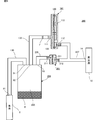
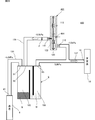
- FIG. 1 is an explanatory diagram of a main part of the fluid control device 100 according to the first embodiment of the present invention.
- the fluid control device 100 is a drainage that sucks a liquid (for example, pleural effusion or blood).
- the fluid control device 100 includes a container 9, a passive valve 101, a tube 130, a tube 135, and a tube 137.
- the fluid control device 100 is connected to the vacuum source 10 and the affected part of the patient 8.
- connection of the vacuum source 10, the affected part of the patient 8, the container 9, the passive valve 101, the tube 130, the tube 135, and the tube 137 is drawn simply.
- any connection method may be adopted for these connections.
- the vacuum source 10 is an arbitrary pump and has a suction hole 14 for sucking air.
- the vacuum source 10 sucks air from the suction hole 14 with a preset suction pressure.
- the passive valve 101 has a first vent hole 111, a second vent hole 112, and a third vent hole 113, which will be described in detail later.
- the third vent hole 113 is open to the atmosphere.
- the container 9 is, for example, a chest drain back.
- the container 9 includes a first connection hole 91, a second connection hole 92, a third connection hole 93, a storage chamber 195, and a water seal chamber 196.
- the water sealed chamber 196 corresponds to an example of the “pressure resistance portion” in the present invention.
- the first end of the tube 130 is connected to the first connection hole 91.
- An inhalation port 81 that is the second end of the tube 130 is inserted into the body of the patient 8. Therefore, the body of the patient 8 communicates with the first connection hole 91 of the container 9 through the tube 130.
- the first end of the tube 135 is connected to the second connection hole 92. Inside the tube 135, a filter F that adsorbs dust contained in the air and dust is provided. The second end of the tube 135 is connected to the first vent hole 111 of the passive valve 101. Therefore, the first ventilation hole 111 of the passive valve 101 communicates with the second connection hole 92 of the container 9.
- the first end of the tube 137 is connected to the third connection hole 93.
- a second end of the tube 137 is connected to the suction hole 14 of the vacuum source 10.
- the third end of the tube 137 is connected to the second vent 112 of the passive valve 101. Therefore, the third connection hole 93 of the container 9 communicates with the suction hole 14 of the vacuum source 10. Further, the second ventilation hole 112 of the passive valve 101 communicates with the suction hole 14 of the vacuum source 10.
- the storage chamber 195 communicates with the first connection hole 91, the second connection hole 92, and the water seal chamber 196.
- the storage chamber 195 stores the liquid B (for example, pleural effusion or blood) of the patient 8 out of the fluid flowing in from the first connection hole 91.
- the water seal chamber 196 communicates with the storage chamber 195 and the third connection hole 93. Water W is placed in the water seal chamber 196.
- the water seal chamber 196 allows the gas out of the fluid flowing in from the first connection hole 91 to pass through the water W and prevents the liquid B from passing therethrough.
- the air that has passed through the water sealing chamber 196 flows out from the third connection hole 93 to the suction hole 14 of the vacuum source 10.
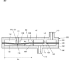
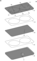
- FIG. 2 is a sectional view of the passive valve 101 shown in FIG. 3 and 4 are exploded perspective views of the passive valve 101 shown in FIG.
- FIG. 3 is an exploded perspective view of the passive valve 101 as viewed from the top surface side
- FIG. 4 is an exploded perspective view of the passive valve 101 as viewed from the bottom surface side.
- the passive valve 101 includes a second valve housing 192, a second sealing material 152, a diaphragm 120, a first sealing material 151, and a first valve housing 191. , They have a stacked structure.
- the first valve housing 191 and the second valve housing 192 constitute a valve housing 190.
- the first valve housing 191 includes a second ventilation hole 112 communicating with the suction hole 14 of the vacuum source 10 and a third ventilation hole 113 communicating with the outside of the valve housing 190.
- a valve seat 139 projecting from the periphery of the third vent hole 113 to the diaphragm 120 side, a cylindrical valve seat 145 projecting to the diaphragm 120 side, and a communication passage 126 communicating the upper valve chamber 142 and the upper valve chamber 134.
- the first valve housing 191 is made of resin, for example.
- the valve seat 139 has a cylindrical shape having a third vent hole 113 at the center.
- the second valve housing 192 is connected to the first ventilation hole 111 communicating with the second connection hole 92 of the container 9, and the communication path communicating the lower valve chamber 141 and the lower valve chamber 132. 136.
- the second valve housing 192 is made of resin, for example.
- the diaphragm 120 is provided with a circular hole 122 at the center of the region facing the valve seat 145.
- the diameter of the hole 122 is provided smaller than the diameter of the surface of the valve seat 145 that contacts the diaphragm 120.
- the diaphragm 120 is made of a rectangular thin film.
- the material of the diaphragm 120 is, for example, rubber such as EPDM (ethylene propylene diene rubber) or silicone.
- EPDM ethylene propylene diene rubber
- the diaphragm 120 is sandwiched between the first valve housing 191 and the second valve housing 192 via the first seal material 151 and the second seal material 152.
- Each of the 1st sealing material 151 and the 2nd sealing material 152 consists of a rectangular-shaped thin film.
- the material of the first sealing material 151 and the second sealing material 152 is, for example, a double-sided tape or an adhesive.
- the first sealing material 151 is provided with a connection hole in a region facing the upper valve chamber 142, the communication path 126, and the upper valve chamber 134.
- the second sealing material 152 is provided with a connection hole in a region facing the lower valve chamber 141, the communication path 136, and the lower valve chamber 132.
- the diaphragm 120 includes a first valve housing 191 and a second valve so that a part of the diaphragm 120 is in contact with the valve seat 139 and the periphery of the hole 122 in the diaphragm 120 is in contact with the valve seat 145. It is fixed to the housing 192. At this time, the valve seat 145 pressurizes the periphery of the hole 122 in the diaphragm 120.
- the diaphragm 120 divides the first valve housing 191 and the second valve housing 192 by being fixed to the first valve housing 191 and the second valve housing 192.
- the diaphragm 120 includes a cylindrical lower valve chamber 141, a cylindrical lower valve chamber 132, a cylindrical upper valve chamber 142, and the like in the first valve housing 191 and the second valve housing 192. And an annular upper valve chamber 134.
- the lower valve chamber 141 communicates with the first vent hole 111.
- the lower valve chamber 132 communicates with the lower valve chamber 141 via the communication path 136.
- the upper valve chamber 142 communicates with the second vent hole 112.
- the upper valve chamber 134 communicates with the upper valve chamber 142 via the communication passage 126.
- the lower valve chamber 141, the communication path 136, and the lower valve chamber 132 correspond to an example of the “first region” in the present invention.
- the upper valve chamber 142, the communication passage 126, and the upper valve chamber 134 correspond to an example of the “second region” in the present invention.
- the diaphragm 120 constitutes the check valve 140 together with the first valve housing 191 and the second valve housing 192.
- the check valve 140 includes a lower valve chamber 141, an upper valve chamber 142, a valve seat 145, a lower valve chamber 141, and a region of the diaphragm 120 facing the upper valve chamber 142.
- the diaphragm 120 configures the exhaust valve 170 together with the first valve housing 191 and the second valve housing 192.
- the exhaust valve 170 includes a lower valve chamber 132, an upper valve chamber 134, a valve seat 139, and a region of the diaphragm 120 facing the lower valve chamber 132 and the upper valve chamber 134.
- the diaphragm 120 contacts or separates from the valve seat 145 due to a pressure difference between the lower valve chamber 141 and the upper valve chamber 142.
- the check valve 140 allows the air flow from the upper valve chamber 142 to the lower valve chamber 141 and blocks the air flow from the lower valve chamber 141 to the upper valve chamber 142.
- the area of the diaphragm 120 facing the lower valve chamber 132 is S1
- the pressure of the lower valve chamber 132 is P1
- the area of the diaphragm 120 facing the upper valve chamber 134 is Is S2
- the pressure of the upper valve chamber 134 is P2
- the area of the diaphragm 120 facing the third vent hole 113 is S3, and the pressure of the third vent hole 113 (atmospheric pressure in this embodiment) is P3.
- S1 ⁇ (P1-P2)> S3 ⁇ (P3-P1) is satisfied, the diaphragm 120 contacts the valve seat 139.
- the relationship of S1 ⁇ (P1-P2) ⁇ S3 ⁇ (P3-P1) is satisfied, the diaphragm 120 is separated from the valve seat 139.
- FIG. 5 is an explanatory diagram showing the flow of fluid in the fluid control device 100 while the vacuum source 10 is on.
- the arrows in the figure indicate the air flow.
- the lower valve chamber 141, the communication path 136, and the lower valve chamber 132 correspond to an example of the “first region” in the present invention.
- the upper valve chamber 142, the communication passage 126, and the upper valve chamber 134 correspond to an example of the “second region” in the present invention.
- the water seal chamber 196 corresponds to an example of the “pressure resistance portion” of the present invention.
- a medical worker inserts the suction port 81 of the tube 130 into the body of the patient 8. Then, the medical worker turns on the vacuum source 10. Note that the pressure in the container 9 before the vacuum source 10 is turned on is atmospheric pressure.
- the vacuum source 10 When the vacuum source 10 is turned on, the vacuum source 10 sucks air from the suction hole 14 with a preset suction pressure (for example, ⁇ 5.0 kPa). Thereby, in the passive valve 101, the air in the upper valve chamber 142 and the upper valve chamber 134 is sucked into the vacuum source 10 from the second vent hole 112 through the suction hole 14. In the container 9, the gas in the storage chamber 195 and the water seal chamber 196 is sucked into the vacuum source 10 from the third connection hole 93 through the suction hole 14.
- a preset suction pressure for example, ⁇ 5.0 kPa
- the water seal chamber 196 makes a difference between the pressure in the storage chamber 195 and the pressure in the suction hole 14. For example, when the height h of the water surface is 2 cm, the water sealed chamber 196 causes a difference of 0.2 kPa in water pressure between the air pressure in the storage chamber 195 and the air pressure in the suction hole 14. Thereby, in the passive valve 101, for example, as shown in FIG. 5, a difference of water pressure of 0.2 kPa occurs between the atmospheric pressure in the first region and the atmospheric pressure in the second region.
- the pressure in the lower valve chamber 141 is higher than the pressure in the upper valve chamber 142. For this reason, the state where the periphery of the hole 122 in the diaphragm 120 remains in contact with the valve seat 145 is maintained, and the communication between the lower valve chamber 141 and the upper valve chamber 142 is blocked.
- the pressure in the lower valve chamber 132 is higher than the pressure in the upper valve chamber 134. For this reason, the diaphragm 120 seals the third vent hole 113 to block communication between the upper valve chamber 134 and the third vent hole 113.
- the passive valve 101 blocks the communication between the first vent 111 and the second vent 112, and the second vent 112 and the third The communication with the vent hole 113 is blocked.
- the fluid control apparatus 100 sucks the fluid in the body of the patient 8 from the suction port 81 into the container 9.
- the liquid B for example, pleural effusion or blood
- the gas passes through the water seal chamber 196.
- the gas that has passed through the water sealing chamber 196 is sucked into the vacuum source 10 from the third connection hole 93 through the suction hole 14.
- FIG. 6 is an explanatory diagram showing the flow of fluid in the fluid control device 100 at the moment when excessive negative pressure is generated in the container 9.
- FIG. 7 is an explanatory diagram showing the flow of fluid in the fluid control device 100 immediately after an excessive negative pressure is generated in the container 9.
- FIG. 8 is a cross-sectional view of the passive valve 101 shown in FIG. The arrows in the figure indicate the air flow.
- an excessive negative pressure higher than the suction pressure of the vacuum source 10 may be generated in the storage chamber 195 of the container 9.
- the water W of the water seal chamber 196 rises toward the storage chamber 195.
- the pressure in the storage chamber 195 may be 1.0 kPa lower than the pressure in the suction hole 14.
- the pressure in the lower valve chamber 141 is lower than the pressure in the upper valve chamber 142. For this reason, as shown in FIGS. 7 and 8, the periphery of the hole 122 in the diaphragm 120 is separated from the valve seat 145, and the lower valve chamber 141 and the upper valve chamber 142 are communicated with each other.
- the pressure in the lower valve chamber 132 is lower than the pressure in the upper valve chamber 134. For this reason, as shown in FIGS. 7 and 8, the diaphragm 120 is separated from the third vent hole 113 to connect the upper valve chamber 134 and the third vent hole 113.
- the passive valve 101 allows the first vent hole 111 and the second vent hole 112 to communicate with each other, and the second vent hole 112 and the third vent hole 113. To communicate with.
- the pressure (air pressure) in the storage chamber 195 increases until the pressure becomes the same as the suction pressure of the vacuum source 10.
- the pressure in the storage chamber 195 becomes the same as the suction pressure of the vacuum source 10
- the pressure in the first region becomes the same as the pressure in the second region.
- the passive valve 101 blocks communication between the first ventilation hole 111 and the second ventilation hole 112 and blocks communication between the second ventilation hole 112 and the third ventilation hole 113.
- the fluid flow returns to the state shown in FIG. That is, the fluid control apparatus 100 can return the pressure in the storage chamber 195 to a preset negative pressure (for example, ⁇ 4.8 kPa).
- the fluid control device 100 having this configuration includes a sensor for detecting excessive negative pressure, an electromagnetic valve for taking outside air into the container 9, and a control device for controlling opening and closing of the electromagnetic valve. Even if you do not have it, you can release excessive negative pressure.
- the fluid control device 100 having this configuration has a simple structure and can reduce the manufacturing cost.
- the medical staff can easily introduce the passive valve 101 into the existing drainage system simply by replacing the sensor, electromagnetic valve, and control device provided in the existing drainage system with the passive valve 101. Therefore, the fluid control apparatus 100 can reduce the introduction cost.
- the medical staff can easily remove the passive valve 101 from the tubes 135 and 137 and replace it with a new one. Therefore, the fluid control apparatus 100 can reduce the maintenance cost of the hospital.
- an intermittent operation in which the vacuum source 10 is repeatedly turned on and off may be performed for the treatment of the patient 8.
- the passive valve 101 immediately after the vacuum source 10 is turned off, in the passive valve 101, air flows into the second region from the suction hole 14 of the vacuum source 10, and the pressure in the first region becomes lower than the pressure in the second region.
- the passive valve 101 passively opens the check valve 140 and the exhaust valve 170 as shown in FIG.
- the fluid control device 100 can release the inside of the container 9 to the atmosphere. Further, while the vacuum source 10 is turned on, the fluid control device 100 can return the pressure in the storage chamber 195 to a preset negative pressure (for example, ⁇ 4.8 kPa) (see FIG. 5).
- a preset negative pressure for example, ⁇ 4.8 kPa
- the pressure in the storage chamber 195 is slightly reduced by the patient 8 breathing normally. Each time the patient 8 normally breathes, it is a burden on the patient 8 that the pressure in the storage chamber 195 returns to the suction pressure of the vacuum source 10 by frequently opening the passive valve 101.
- the passive valve 101 adjusts the dimensions of the protrusions 139 and 145 shown in FIG. Thereby, the passive valve 101 can adjust the pressure which the passive valve 101 opens. For example, the passive valve 101 can be adjusted to not open when the patient 8 normally breathes and to open when the patient 8 coughs or sneezes. Thus, the passive valve 101 can immediately return the pressure in the storage chamber 195 to the suction pressure of the vacuum source 10 only when the patient 8 coughs or sneezes.
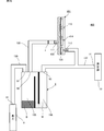
- FIG. 9 is an explanatory diagram of a main part of the fluid control device 200 according to the second embodiment of the present invention.
- FIG. 10 is a sectional view of the passive valve 201 shown in FIG.
- the fluid control device 200 is different from the fluid control device 100 in that a passive valve 201 is provided instead of the water seal chamber 196. Since other configurations are the same, description thereof is omitted.
- the passive valve 201 corresponds to an example of the “pressure resistance unit” in the present invention.
- the difference between the container 209 and the container 9 is that the water-sealed chamber 196 is not provided.
- the container 209 includes a first connection hole 91, a second connection hole 92, a third connection hole 93, and a storage chamber 295.
- the passive valve 201 includes a second valve housing 292, a second sealing material (not shown), a diaphragm 220, a first sealing material (not shown), and a first valve housing 291. And have a structure in which they are sequentially stacked.
- the first valve housing 291 and the second valve housing 292 constitute a valve housing 290.
- the first valve housing 291 has a second ventilation hole 212 communicating with the suction hole 14 of the vacuum source 10.
- the first valve housing 291 is made of resin, for example.
- the second valve housing 292 includes a first vent hole 211 communicating with the third connection hole 93 of the container 209 and a cylindrical valve seat 238 protruding toward the diaphragm 220 side.
- the second valve housing 292 is made of resin, for example.
- the diaphragm 220 is provided with a circular hole 221 at the center of the region facing the valve seat 238.
- the diameter of the hole 221 is provided smaller than the diameter of the surface of the valve seat 238 that contacts the diaphragm 220.
- the diaphragm 220 is sandwiched between the first valve housing 291 and the second valve housing 292 via the first seal material and the second seal material.
- the diaphragm 220 is fixed to the first valve housing 291 and the second valve housing 292 so that the periphery of the hole 221 in the diaphragm 220 is in contact with the valve seat 238. At this time, the valve seat 238 pressurizes the periphery of the hole 221 in the diaphragm 220.
- the diaphragm 220 divides the first valve housing 291 and the second valve housing 292 by being fixed to the first valve housing 291 and the second valve housing 292. Accordingly, the diaphragm 220 forms an annular lower valve chamber 231 and a cylindrical upper valve chamber 233 in the first valve housing 291 and the second valve housing 292.
- the diaphragm 220 configures the check valve 260 together with the first valve housing 291 and the second valve housing 292.
- the check valve 260 includes a lower valve chamber 231, an upper valve chamber 233, a valve seat 238, and a region of the diaphragm 220 facing the lower valve chamber 231 and the upper valve chamber 233.
- the diaphragm 220 contacts or separates from the valve seat 238 due to a pressure difference between the lower valve chamber 231 and the upper valve chamber 233.
- the check valve 260 allows the air flow from the lower valve chamber 231 to the upper valve chamber 233 and blocks the air flow from the upper valve chamber 233 to the lower valve chamber 231.
- the first end of the tube 235 is connected to the third connection hole 93.
- a second end of the tube 235 is connected to the first vent hole 211.
- a first end of the tube 237 is connected to the second vent 212 of the passive valve 201.
- a second end of the tube 237 is connected to the suction hole 14 of the vacuum source 10.
- a third end of the tube 237 is connected to the second vent 112 of the passive valve 101.
- FIG. 11 is an explanatory diagram showing the flow of fluid in the fluid control device 200 while the vacuum source 10 is on.
- FIG. 12 is an explanatory diagram showing the flow of fluid in the fluid control device 200 immediately after excessive negative pressure is generated in the container 9. The arrows in the figure indicate the air flow.
- the passive valve 201 makes a difference between the pressure in the storage chamber 295 and the pressure in the suction hole 14. For example, when 0.2 kPa is required to open the check valve 260, the passive valve 201 causes a difference of 0.2 kPa between the pressure in the storage chamber 295 and the pressure in the suction hole 14. Thereby, in the passive valve 101, for example, a difference of 0.2 kPa is generated between the atmospheric pressure in the first region and the atmospheric pressure in the second region. Therefore, the fluid control apparatus 200 can be used also in the container 209 that does not include the water seal chamber 196.
- the fluid flow of the fluid control device 200 immediately after an excessive negative pressure is generated in the container 9 is the same as the fluid flow of the fluid control device 100 shown in FIG. 7, as shown in FIG. Therefore, the fluid control device 200 has the same effect as the fluid control device 100.
- FIG. 13 is an explanatory diagram of a main part of the fluid control device 300 according to the third embodiment of the present invention.
- 14 is a cross-sectional view of the passive valve 301 shown in FIG.
- FIG. 15 is an exploded perspective view of the passive valve 101 shown in FIG.
- FIG. 16 is an exploded perspective view of the passive valve 101 shown in FIG.
- the fluid control device 300 is different from the fluid control device 100 in that the passive valve 301 includes a check valve 260.
- the fluid control device 300 is different from the fluid control device 200 in that a passive valve 301 in which the passive valve 101 and the passive valve 201 are integrated is provided. Since other configurations are the same, description thereof is omitted.
- the check valve 260 and the water seal chamber 196 provided in the passive valve 301 correspond to an example of the “pressure resistance portion” of the present invention.
- the difference between the diaphragm 320 and the diaphragm 120 is that it has a hole 221. Since other configurations are the same, description thereof is omitted.
- the second valve housing 392 has a structure in which the second valve housing 192 and the second valve housing 292 are integrated. As shown in FIGS. 14 and 15, the second valve housing 392 includes a wall portion 330 that separates the lower valve chamber 341 and the lower valve chamber 231. Since other configurations are the same, description thereof is omitted.
- first end of the tube 337 is connected to the third vent hole 112 of the passive valve 301.
- a second end of the tube 337 is connected to the suction hole 14 of the vacuum source 10.
- FIG. 17 is an explanatory diagram showing the flow of fluid in the fluid control device 300 while the vacuum source 10 is on.
- FIG. 18 is an explanatory diagram showing the flow of fluid in the fluid control device 300 immediately after an excessive negative pressure is generated in the container 9.
- the arrows in the figure indicate the air flow.
- the check valve 260 and the water seal chamber 196 of the passive valve 301 cause a difference between the air pressure in the storage chamber 195 and the air pressure in the suction hole 14.
- the check valve 260 and the water seal chamber 196 cause a difference of 0.4 kPa between the pressure in the storage chamber 295 and the pressure in the suction hole 14.
- the fluid control apparatus 200 can cause a pressure difference in the check valve 260 even when the water surface height h varies in the water seal chamber 196. Therefore, the fluid control apparatus 200 can perform a stable operation even when the water surface height h varies in the water seal chamber 196.
- the flow of fluid in the fluid control apparatus 300 immediately after an excessive negative pressure is generated in the container 9 is the same as the flow of fluid in the fluid control apparatus 100 shown in FIG. 7, as shown in FIG. Therefore, the fluid control device 300 also has the same effect as the fluid control device 100.
- the fluid control device 300 can shorten the length of the tube as compared with the fluid control device 200.
- FIG. 19 is a cross-sectional view of a main part of a fluid control apparatus 400 according to the fourth embodiment of the present invention.
- 20 is a cross-sectional view of the passive valve 401 shown in FIG. The arrows in the figure indicate the air flow.
- a difference between the fluid control device 400 and the fluid control device 100 is a passive valve 401.
- the passive valve 401 is different from the passive valve 101 in that it has a fourth vent hole 414.
- the cross-sectional area of the fourth vent hole 414 is extremely smaller than the cross-sectional area of the vent path formed inside the tube 137. Since the configuration of the other fluid control device 400 is the same as that of the fluid control device 100, description thereof is omitted.
- FIG. 21 is an explanatory diagram showing the flow of fluid in the fluid control device 400 while the vacuum source 10 is on.
- FIG. 22 is an explanatory diagram illustrating the flow of fluid in the fluid control device 400 immediately after an excessive negative pressure is generated in the container 9.
- the fluid flow of the fluid control device 400 while the vacuum source 10 is on is substantially the same as the fluid flow of the fluid control device 100 shown in FIG.
- the vacuum source 10 is immediately after an excessive negative pressure is generated in the container 9 or in the intermittent operation described above. Immediately after is turned off.
- the passive valve 401 immediately after the vacuum source 10 is turned off in the intermittent operation described above, in the passive valve 401, a small amount of air is sucked from the outside of the passive valve 401 into the passive valve 401 through the fourth vent hole 414. Therefore, in the passive valve 401, the speed at which the diaphragm 120 opens the third ventilation hole 113 is increased. Therefore, immediately after the vacuum source 10 is turned off, the fluid control device 400 can quickly release the inside of the container 9 to the atmosphere.
- the fluid control device 400 also has the same effect as the fluid control device 100.
- tubes other than the tube 135 may have a filter.
Landscapes
- Health & Medical Sciences (AREA)
- Heart & Thoracic Surgery (AREA)
- Vascular Medicine (AREA)
- Engineering & Computer Science (AREA)
- Anesthesiology (AREA)
- Biomedical Technology (AREA)
- Hematology (AREA)
- Life Sciences & Earth Sciences (AREA)
- Animal Behavior & Ethology (AREA)
- General Health & Medical Sciences (AREA)
- Public Health (AREA)
- Veterinary Medicine (AREA)
- External Artificial Organs (AREA)
Abstract
Priority Applications (3)
| Application Number | Priority Date | Filing Date | Title |
|---|---|---|---|
| DE112016001939.4T DE112016001939T5 (de) | 2015-05-28 | 2016-05-24 | Fluidsteuervorrichtung |
| JP2017520706A JP6260739B2 (ja) | 2015-05-28 | 2016-05-24 | 流体制御装置 |
| US15/822,484 US11446415B2 (en) | 2015-05-28 | 2017-11-27 | Fluid control device |
Applications Claiming Priority (2)
| Application Number | Priority Date | Filing Date | Title |
|---|---|---|---|
| JP2015-108972 | 2015-05-28 | ||
| JP2015108972 | 2015-05-28 |
Related Child Applications (1)
| Application Number | Title | Priority Date | Filing Date |
|---|---|---|---|
| US15/822,484 Continuation US11446415B2 (en) | 2015-05-28 | 2017-11-27 | Fluid control device |
Publications (1)
| Publication Number | Publication Date |
|---|---|
| WO2016190289A1 true WO2016190289A1 (fr) | 2016-12-01 |
Family
ID=57392808
Family Applications (1)
| Application Number | Title | Priority Date | Filing Date |
|---|---|---|---|
| PCT/JP2016/065237 WO2016190289A1 (fr) | 2015-05-28 | 2016-05-24 | Dispositif de régulation de fluide |
Country Status (4)
| Country | Link |
|---|---|
| US (1) | US11446415B2 (fr) |
| JP (1) | JP6260739B2 (fr) |
| DE (1) | DE112016001939T5 (fr) |
| WO (1) | WO2016190289A1 (fr) |
Families Citing this family (1)
| Publication number | Priority date | Publication date | Assignee | Title |
|---|---|---|---|---|
| WO2018101143A1 (fr) * | 2016-11-29 | 2018-06-07 | 株式会社村田製作所 | Unité d'aspiration et de décharge et dispositif d'aspiration et de décharge |
Citations (5)
| Publication number | Priority date | Publication date | Assignee | Title |
|---|---|---|---|---|
| JPS632042Y2 (fr) * | 1984-09-05 | 1988-01-19 | ||
| JPH0126703B2 (fr) * | 1986-04-21 | 1989-05-25 | Sumitomo Bakelite Co | |
| JPH0412984B2 (fr) * | 1987-01-06 | 1992-03-06 | Bioresearch Inc | |
| JP2587815Y2 (ja) * | 1992-11-12 | 1998-12-24 | 日本シャーウッド株式会社 | 吸引制御機能付きコネクタ |
| JP3935340B2 (ja) * | 2001-11-22 | 2007-06-20 | バグノリ マリア | ガス圧均衡/ガス供給制御装置 |
Family Cites Families (4)
| Publication number | Priority date | Publication date | Assignee | Title |
|---|---|---|---|---|
| GB2048485B (en) | 1979-05-11 | 1984-01-11 | Pye Electronic Prod Ltd | Detecting changes in body shape |
| US20080015526A1 (en) * | 2006-05-23 | 2008-01-17 | Solomon Reiner | Suction canister |
| CN102032445B (zh) * | 2010-11-22 | 2013-03-27 | 秦皇岛莱特流体设备制造有限公司 | 一种利用煤气排水器取压的方法及实现取压的煤气排水器 |
| WO2016194564A1 (fr) * | 2015-05-29 | 2016-12-08 | 株式会社村田製作所 | Dispositif d'aspiration |
-
2016
- 2016-05-24 WO PCT/JP2016/065237 patent/WO2016190289A1/fr active Application Filing
- 2016-05-24 DE DE112016001939.4T patent/DE112016001939T5/de active Granted
- 2016-05-24 JP JP2017520706A patent/JP6260739B2/ja active Active
-
2017
- 2017-11-27 US US15/822,484 patent/US11446415B2/en active Active
Patent Citations (5)
| Publication number | Priority date | Publication date | Assignee | Title |
|---|---|---|---|---|
| JPS632042Y2 (fr) * | 1984-09-05 | 1988-01-19 | ||
| JPH0126703B2 (fr) * | 1986-04-21 | 1989-05-25 | Sumitomo Bakelite Co | |
| JPH0412984B2 (fr) * | 1987-01-06 | 1992-03-06 | Bioresearch Inc | |
| JP2587815Y2 (ja) * | 1992-11-12 | 1998-12-24 | 日本シャーウッド株式会社 | 吸引制御機能付きコネクタ |
| JP3935340B2 (ja) * | 2001-11-22 | 2007-06-20 | バグノリ マリア | ガス圧均衡/ガス供給制御装置 |
Also Published As
| Publication number | Publication date |
|---|---|
| US20180071440A1 (en) | 2018-03-15 |
| DE112016001939T5 (de) | 2018-02-15 |
| US11446415B2 (en) | 2022-09-20 |
| JP6260739B2 (ja) | 2018-01-17 |
| JPWO2016190289A1 (ja) | 2018-02-15 |
Similar Documents
| Publication | Publication Date | Title |
|---|---|---|
| US11850127B2 (en) | Multi-lumen bridge for negative pressure wound therapy system | |
| US11717655B2 (en) | Apparatus for topical negative pressure therapy | |
| US8303552B2 (en) | Reduced pressure wound treatment system | |
| US8585665B2 (en) | Transmissive dressing for negative pressure wound therapy | |
| US10569076B2 (en) | Valve and fluid control device | |
| ES2391527T5 (es) | Sistema de drenaje y cierre de heridas | |
| US11439734B2 (en) | Breast pump and expression kit for a breast pump | |
| US4911697A (en) | Chest drainage unit having increased airflow capacity with capability to dampon noise | |
| JP5850210B1 (ja) | バルブ、流体制御装置 | |
| JP2019527119A5 (fr) | ||
| WO2020095721A1 (fr) | Machine d'aspiration médicale | |
| JP6260739B2 (ja) | 流体制御装置 | |
| JP2015024086A (ja) | 液状廃棄物処理容器 | |
| JP2010535603A (ja) | 流体システム内の気泡を低減する方法および配置 | |
| WO2009016195A2 (fr) | Dispositif de traitement de blessure | |
| US11167072B2 (en) | Suction discharge unit and suction discharge device | |
| CN105848691A (zh) | 储存容器 | |
| JP2016049235A (ja) | 排液処理器 |
Legal Events
| Date | Code | Title | Description |
|---|---|---|---|
| 121 | Ep: the epo has been informed by wipo that ep was designated in this application |
Ref document number: 16799994 Country of ref document: EP Kind code of ref document: A1 |
|
| ENP | Entry into the national phase |
Ref document number: 2017520706 Country of ref document: JP Kind code of ref document: A |
|
| WWE | Wipo information: entry into national phase |
Ref document number: 112016001939 Country of ref document: DE |
|
| 122 | Ep: pct application non-entry in european phase |
Ref document number: 16799994 Country of ref document: EP Kind code of ref document: A1 |