WO2016190124A1 - 歯車機構の組立装置および組立方法 - Google Patents
歯車機構の組立装置および組立方法 Download PDFInfo
- Publication number
- WO2016190124A1 WO2016190124A1 PCT/JP2016/064201 JP2016064201W WO2016190124A1 WO 2016190124 A1 WO2016190124 A1 WO 2016190124A1 JP 2016064201 W JP2016064201 W JP 2016064201W WO 2016190124 A1 WO2016190124 A1 WO 2016190124A1
- Authority
- WO
- WIPO (PCT)
- Prior art keywords
- gear
- image processing
- center
- phase
- image
- Prior art date
- Legal status (The legal status is an assumption and is not a legal conclusion. Google has not performed a legal analysis and makes no representation as to the accuracy of the status listed.)
- Ceased
Links
Images


Classifications
-
- F—MECHANICAL ENGINEERING; LIGHTING; HEATING; WEAPONS; BLASTING
- F16—ENGINEERING ELEMENTS AND UNITS; GENERAL MEASURES FOR PRODUCING AND MAINTAINING EFFECTIVE FUNCTIONING OF MACHINES OR INSTALLATIONS; THERMAL INSULATION IN GENERAL
- F16H—GEARING
- F16H57/00—General details of gearing
- F16H57/02—Gearboxes; Mounting gearing therein
- F16H57/023—Mounting or installation of gears or shafts in the gearboxes, e.g. methods or means for assembly
-
- B—PERFORMING OPERATIONS; TRANSPORTING
- B23—MACHINE TOOLS; METAL-WORKING NOT OTHERWISE PROVIDED FOR
- B23P—METAL-WORKING NOT OTHERWISE PROVIDED FOR; COMBINED OPERATIONS; UNIVERSAL MACHINE TOOLS
- B23P19/00—Machines for simply fitting together or separating metal parts or objects, or metal and non-metal parts, whether or not involving some deformation; Tools or devices therefor so far as not provided for in other classes
- B23P19/04—Machines for simply fitting together or separating metal parts or objects, or metal and non-metal parts, whether or not involving some deformation; Tools or devices therefor so far as not provided for in other classes for assembling or disassembling parts
-
- B—PERFORMING OPERATIONS; TRANSPORTING
- B23—MACHINE TOOLS; METAL-WORKING NOT OTHERWISE PROVIDED FOR
- B23P—METAL-WORKING NOT OTHERWISE PROVIDED FOR; COMBINED OPERATIONS; UNIVERSAL MACHINE TOOLS
- B23P21/00—Machines for assembling a multiplicity of different parts to compose units, with or without preceding or subsequent working of such parts, e.g. with program control
-
- B—PERFORMING OPERATIONS; TRANSPORTING
- B25—HAND TOOLS; PORTABLE POWER-DRIVEN TOOLS; MANIPULATORS
- B25J—MANIPULATORS; CHAMBERS PROVIDED WITH MANIPULATION DEVICES
- B25J13/00—Controls for manipulators
- B25J13/08—Controls for manipulators by means of sensing devices, e.g. viewing or touching devices
-
- B—PERFORMING OPERATIONS; TRANSPORTING
- B25—HAND TOOLS; PORTABLE POWER-DRIVEN TOOLS; MANIPULATORS
- B25J—MANIPULATORS; CHAMBERS PROVIDED WITH MANIPULATION DEVICES
- B25J9/00—Program-controlled manipulators
- B25J9/16—Program controls
- B25J9/1679—Program controls characterised by the tasks executed
- B25J9/1687—Assembly, peg and hole, palletising, straight line, weaving pattern movement
-
- B—PERFORMING OPERATIONS; TRANSPORTING
- B25—HAND TOOLS; PORTABLE POWER-DRIVEN TOOLS; MANIPULATORS
- B25J—MANIPULATORS; CHAMBERS PROVIDED WITH MANIPULATION DEVICES
- B25J9/00—Program-controlled manipulators
- B25J9/16—Program controls
- B25J9/1694—Program controls characterised by use of sensors other than normal servo-feedback from position, speed or acceleration sensors, perception control, multi-sensor controlled systems, sensor fusion
- B25J9/1697—Vision controlled systems
-
- F—MECHANICAL ENGINEERING; LIGHTING; HEATING; WEAPONS; BLASTING
- F16—ENGINEERING ELEMENTS AND UNITS; GENERAL MEASURES FOR PRODUCING AND MAINTAINING EFFECTIVE FUNCTIONING OF MACHINES OR INSTALLATIONS; THERMAL INSULATION IN GENERAL
- F16H—GEARING
- F16H57/00—General details of gearing
-
- F—MECHANICAL ENGINEERING; LIGHTING; HEATING; WEAPONS; BLASTING
- F16—ENGINEERING ELEMENTS AND UNITS; GENERAL MEASURES FOR PRODUCING AND MAINTAINING EFFECTIVE FUNCTIONING OF MACHINES OR INSTALLATIONS; THERMAL INSULATION IN GENERAL
- F16H—GEARING
- F16H57/00—General details of gearing
- F16H2057/0043—Mounting or adjusting transmission parts by robots
Definitions
- the present invention relates to a gear mechanism assembling apparatus and a method for assembling a gear mechanism by fitting gears together.
- Patent Document 1 in a robot hand in which a cushion mechanism portion, an RCC mechanism portion, and a work chuck mechanism portion are connected, the work chuck mechanism portion is incorporated into the RCC mechanism portion, whereby an RCC mechanism based on weight is obtained. This makes it possible to perform not only vertical assembly work but also horizontal assembly work.
- the conventional robot hand adopting the above-described RCC is intended to insert a simple circular cross-section shaft into a simple circular cross-section shaft hole. For this reason, for example, when a gear mechanism is assembled by fitting gears together, automation by a robot is extremely difficult or impossible.
- the present invention has been made in view of the above-described problems of the prior art, and provides a gear mechanism assembling apparatus and a method for assembling a gear mechanism without hindrance by fitting the gears together using a robot. With the goal.
- a first aspect of the present invention is a gear mechanism assembling apparatus for assembling a gear mechanism by fitting a second gear to a first gear, the second gear.
- a robot having a hand for holding the first gear, a first imaging device provided on the hand for imaging the first gear, and a second imaging device for imaging the second gear
- the image captured by the first imaging device is subjected to image processing to obtain the fitting position of the second gear and the phase of the first gear, and the image captured by the second imaging device is imaged.
- An image processing system for processing to obtain the phase of the second gear and the position of the gear shaft of the second gear, and controlling the robot based on information obtained by the image processing system.
- held in the hand The gear shaft of the second gear is aligned with the fitting position of the second gear in the first gear, and the phase of the second gear is aligned with the phase of the first gear.
- the gear mechanism is configured to be assembled using the robot.
- the image processing system detects an area of the first gear by performing image processing on an image of the first gear, and detects the detected first gear. And a first image processing means for acquiring a fitting position of the second gear and a phase of the first gear based on the region of the first gear.
- the first gear has a plurality of planetary gears
- the first image processing means performs imaging based on a region of the first gear. Extracting valley portions of the plurality of planetary gears included in the image, the centers of circumscribed circles circumscribing a plurality of arcs with the center of gravity of the extracted valley portions as points on the circumference in the first gear
- the first gear has a plurality of planetary gears
- the first image processing means is based on the region of the first gear.
- the center of a circumscribed circle that circumscribes a plurality of arcs that extract a valley portion of the plurality of planetary gears included in the captured image of the first imaging device and that has a center of gravity of the extracted valley portion as a point on the circumference Is the fitting position of the second gear in the first gear
- the length on the circumscribed circle from the contact point with the circumscribed circle in any of the plurality of arcs with the center of the circumscribed circle as a reference Is a direction toward the point on the circumference of the circumscribed circle that is equal to the circumferential length of the arc between the center of gravity of the valley portion that is closest to the contact point in the arc and the contact point. It is specified as the phase of the first gear. To.
- the image processing system detects an area of the second gear by performing image processing on the image of the second gear, Second image processing means for acquiring a position of a tip end portion and a root portion of the gear shaft of the second gear and a phase of the second gear based on the detected region of the second gear. It is characterized by having.
- a sixth aspect of the present invention based on the position of the tip end portion and the root portion of the gear shaft of the second gear acquired by the second image processing means, Obtaining the axial direction of the second gear, and controlling the robot to correct the displacement of the holding position of the second gear by the hand based on the axial direction of the second gear.
- the second image processing means acquires the position of the tip end portion and the position of the root portion of the gear shaft of the second gear
- the second gear is imaged again by the second imaging device after being rotated by a preset angle
- the second image processing means is used to re-imaging the gear shaft of the second gear based on the second captured image.
- the position of the tip portion and the position of the root portion are obtained again, and based on the information about the position of the tip portion of the gear shaft and the position of the root portion of the second gear obtained two times before and after the second gear
- the second gear And the robot is controlled so as to correct the shift of the holding position of the second gear by the hand based on the axial direction of the second gear.
- the second gear is provided on an output shaft of a motor, and the hand is configured to grip the motor.
- the hand is provided with an optical sensor for measuring the distance to the object on which the motor is mounted.
- the gear mechanism is a planetary gear mechanism
- the first gear is a planetary gear of the planetary gear mechanism
- the second gear is a sun gear of the planetary gear mechanism.
- a tenth aspect of the present invention is a gear mechanism assembling method for assembling a gear mechanism by fitting a second gear to a first gear using a robot, and the second gear in the first gear.
- the robot is controlled based on the information acquired by the first gear measurement step and the second gear measurement step, and the gear shaft of the second gear held in the hand of the robot is changed to the first gear shaft.
- the gear mechanism is assembled by using the robot by aligning the second gear with the fitting position of the second gear and aligning the phase of the second gear with the phase of the first gear. That, characterized in that.
- the first gear measurement step acquires an image of the first gear using an imaging device provided in the hand and performs image processing.
- a first image processing step wherein the first image processing step detects an image of the first gear by image processing the image of the first gear, and the detected first gear; On the basis of the region, the fitting position of the second gear in the first gear and the phase of the first gear are obtained.
- the first gear has a plurality of planetary gears
- the first image processing step performs imaging based on the region of the first gear. Extracting valley portions of the plurality of planetary gears included in the image, the centers of circumscribed circles circumscribing a plurality of arcs with the center of gravity of the extracted valley portions as points on the circumference in the first gear
- the first gear has a plurality of planetary gears
- imaging is performed based on the region of the first gear.
- the length of the circumscribed circle from the contact point with the circumscribed circle in any one of the plurality of arcs with respect to the center of the circumscribed circle is set as the fitting position of the second gear.
- the direction toward the circumferential point of the circumscribed circle that is equal to the circumferential length of the arc between the center of gravity of the valley portion present at the closest position to the contact point is the phase of the first gear It is characterized by specifying.
- the second gear measurement step obtains an image of the second gear and performs image processing.
- the second image processing step detects an area of the second gear by image-processing an image of the second gear, and based on the detected area of the second gear, the second gear
- tip part of this gear shaft, the position of a base part, and the phase of a said 2nd gearwheel are acquired, It is characterized by the above-mentioned.
- the second aspect is based on the position of the tip end portion and the root portion of the gear shaft of the second gear acquired by the second image processing step. Obtaining the axial direction of the second gear, and controlling the robot so as to correct the displacement of the holding position of the second gear by the hand based on the axial direction of the second gear.
- the fifteenth aspect after obtaining the position of the tip end portion and the position of the root portion of the gear shaft of the second gear in the second gear measurement step, Rotate a preset angle, image the second gear again, and acquire again the position of the tip portion and the root portion of the gear shaft of the second gear based on the captured image again, Based on the information about the position of the tip end portion and the position of the root portion of the gear shaft of the second gear acquired twice before and after, the axial direction of the second gear is acquired, and the second gear The robot is controlled based on an axial direction so as to correct a shift in the holding position of the second gear by the hand.
- the second gear is provided on an output shaft of a motor, and the hand is configured to grip the motor.
- the distance to the object to which the motor is mounted is measured by an optical sensor provided on the hand, and a base coordinate system for the object is generated based on the measurement result. To do.
- the gear mechanism is a planetary gear mechanism
- the first gear is a planetary gear of the planetary gear mechanism
- the second gear is a sun gear of the planetary gear mechanism.
- the gear mechanism assembling apparatus 1 is mounted on the wrist of a robot (hereinafter referred to as “working robot”) 2 and work robot 2 used for assembling gears.
- the hand 3 is further equipped with an optical sensor 23 such as a laser distance sensor.
- the optical sensor 2 can be used to measure the distance to the object to which the workpiece is attached.
- the image processing system 11 includes a first image processing unit 12 that processes an image captured by the first imaging device 21 and a first image processing unit 13 that processes an image captured by the second imaging device 22. It has.
- the first image processing unit 12 and the second image processing unit 13 may be completely independent devices as hardware, or are arranged in an integrated device as hardware, and are integrated in the device. It may be configured as a subcomponent with some common elements, and it is also integrated as hardware inside the device, but it may be part of the software as a common component or as a subcomponent good.
- the work robot 2 uses an articulated robot having six axes, and the robot control device 4 controls an arbitrary position and direction in the space of the wrist and the operation path.
- the work robot in the present invention is not limited to the 6-axis articulated robot.
- a CCD camera or the like is used for the first imaging device 21 and the second imaging device 22.
- the gear mechanism to be assembled is a mechanism having three planetary gears around one sun gear arranged at the center.
- the gear mechanism that can be assembled by the gear mechanism assembling apparatus according to the present invention is not limited to the gear mechanism having this configuration.
- the gear assembling apparatus 1 is, for example, a motor for a reduction gear 31 (FIG. 2) that is already incorporated in a drive shaft of a robot (hereinafter referred to as “product robot”) 61 that is being manufactured and assembled.
- the motor side gear 43 (FIG. 3) attached to the output shaft 42 of 41 is fitted together, and the output shaft 42 is inserted into the speed reducer gear 31 to assemble the speed reducer gear 31 and the motor side gear 43. is there.
- the axial direction of the output shaft 42 of the motor 41 mounted on the drive shaft of the product robot 61 is not limited to the vertical direction and is often arranged in the horizontal direction.
- the operation of combining the motor side gear 43 of the motor 41 having the shaft 42 with the reduction gear 31 by the work robot 1 is a horizontal assembly operation.
- the present embodiment can cope with a case where the work including the gears to be combined is heavy and the assembly of the gears by the horizontal assembling work is performed by the work robot.
- the planetary gear 44 incorporating the motor side gear 43 attached to the output shaft 42 of the motor 41 is incorporated in the casing of the speed reducer. From the outside, it can be seen only through the insertion hole 46 for inserting the output shaft 42 into the casing.
- the tip end axis of the output shaft 42 is aligned with the target position to be the axis of the motor side gear 43 after assembly in the planetary gear 44, and It is necessary to adjust the angle of the output shaft 42 so that the phase of the motor side gear 43 corresponds to the phase of the planetary gear 44 and insert the output shaft 42 into the planetary gear 44 for incorporation.
- the target position to be the axis of the motor-side gear 43 and the phase of the planetary gear 44 are measured in the planetary gear 44 after assembling.
- the first imaging device 21 mounted on the hand 3 of the work robot 2 captures an image including the speed reducer gear 31 through the insertion hole 46, and the image captured by the first imaging device 21. Is subjected to image processing in the first image processing unit 12 of the image processing system 11 to calculate the reduction gear gear characteristic information.
- the measurement of the reduction gear gear characteristic information is started by a command signal from the robot control device 4 to the first image processing unit 12, and the first image processing unit 12 receiving the command signal receives the first imaging device.
- An imaging command signal is transmitted to 21, and imaging is performed by the first imaging device 21.
- the captured image is transmitted from the first imaging device 21 to the first image processing unit 12, subjected to image processing, and a calculated value is transmitted to the robot control device 4.
- the target position to be the axis of the motor side gear 43 after assembly in the planetary gear 44 is equidistant from all the planetary gears 44 in the region surrounded by all the planetary gears 44. Calculated and identified as a point in
- Both gears can be fitted by inserting the motor side gear 43 into the reducer gear 31 so that the valley portion of the reducer gear 31 and the peak portion of the motor side gear 43 coincide.
- the direction of the valley portion of the planetary gear 44 (hereinafter referred to as “phase of the planetary gear” or “reduction gear”
- the phase of the crest portion of the motor-side gear 43 (hereinafter referred to as “phase of the motor-side gear”) is basically measured in the above-described direction of the phase of the planetary gear 44. This can be done by adjusting and aligning.
- the valley portion of the planetary gear 44 it is necessary to select a specific position for the valley portion of the planetary gear 44.
- this specific position for example, the midpoint of the valley portion of the pitch circle can be considered, but in consideration of the ease of image processing and the like, in this embodiment, the center of gravity of the valley portion of the planetary gear 44 and To do.
- the specific position of the peak portion of the motor side gear 43 to be inserted is the same, and the midpoint of the peak portion of the pitch circle of the gear can be considered, but the direction of the center line of the gear peak portion that is line symmetric Based on.
- Region detection of planetary gear 44 The contour line of the planetary gear 44 is extracted using other image processing means such as binarization of the captured image, and pattern matching with the shape of the planetary gear 44 stored in advance results in the region of the planetary gear 44 being Perform detection.
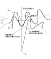
- the region of the planetary gear 44 is a portion surrounded by the tooth-shaped boundary line of the planetary gear 44 and the arc of the insertion hole 46 in FIG.
- the circumscribed circle b corresponds to the motor-side gear 43 fitted with the planetary gear 44 and the center point B corresponds to the axis of the motor-side gear 43, the circumscribed circle b is hereinafter referred to as “motor-side gear insertion shaft hole”,
- the center point B of the circumscribed circle may be referred to as an “insertion shaft hole axis”.
- the circumscribed circle b and its center point B can be calculated by the following method.
- the direction of the motor side gear 43 to be inserted into the planetary gear 44 is adjusted not to the direction of the center of gravity of the valley portion of the planetary gear 44 but to the direction derived by the following method,
- the side gear 43 is incorporated in the planetary gear 44.
- the length DE between the contact point D and the center of gravity E on the circumference of the arc a i is calculated, and the length from the contact point D on the circumference of the circumscribed circle is the circle.
- the point F that is equal to the circumferential length DE is calculated and the motor side gear 43 is assembled into the motor side gear insertion shaft hole of the planetary gear 44, the center line direction of the crest portion of the motor side gear 43 is Suppose that it is adjusted and inserted so that it may become the direction BF calculated above.
- the motor side gear 43 and the planetary gear 44 can be accurately fitted.
- the center position of the tip end portion of the output shaft 42 and the axial deviation are measured, and the phase of the motor side gear 43 is measured.
- the tip position and the axial direction of the output shaft 42 and the phase of the motor side gear 43 coincide with the axis of the insertion shaft hole and the axis of the insertion shaft hole in the reduction gear 31 and the phase of the planetary gear 44, respectively.
- the measurement of the motor side gear 43 is started by a command signal from the robot control device 4 to the second image processing unit 13, and the second image processing unit 13 that has received the command signal sends the second imaging device 22 to the second imaging device 22.
- an imaging command signal is transmitted, and imaging is performed by the second imaging device 22.
- the work robot 1 moves the motor 41 held by the hand 3 to the visual field range of the second imaging device 22.
- the captured image is transmitted from the second imaging device 22 to the second image processing unit 13, and the phase of the motor-side gear 43 calculated by image processing is transmitted to the robot control device 4.
- the center position of the tip end of the output shaft 42 calculated by the second image processing unit 13 and the axial shift and the phase of the motor-side gear 43 are transmitted to the robot controller 4 of the work robot 2 and the tool coordinate system is reproduced. It is used for setting and executing the operation control of the motor side gear 43.
- the plane of the root portion of the motor 41 of the output shaft 42 is the XY coordinate plane, and the axis of the output shaft 42 is the Z coordinate axis (the direction toward the tip end of the output shaft is normal).
- the motor-side gear 43 is incorporated in the reduction gear 31, the motor 41 held by the work robot 2 is controlled to operate in the tool coordinate system Z-axis direction.
- the second imaging device 22 performs imaging so that the distal end portion of the output shaft 42 and the motor-side gear 43 are included in the visual field range.
- the image acquired by the second imaging device 22 is transmitted to the second image processing unit 13, and the second image processing unit 13 calculates the tip center position P of the output shaft 42 and the phase of the motor side gear 43. Is done.
- the work robot 2 is operated to move the motor 41 backward by a distance corresponding to the length of the output shaft 42 in the direction away from the second imaging device 22 in the axial direction of the output shaft 42, and then the second imaging device 22.
- imaging is performed so that the base portion of the output shaft 42 is included in the visual field range.
- the image acquired by the second imaging device 22 is transmitted to the second image processing unit 13, and the second image processing unit 13 uses a technique such as binarization processing at the root of the output shaft 42.
- the contour line is extracted, and the root center position Q of the output shaft 42 is calculated using the geometric feature that the cross-sectional shape of the root is circular.
- the motor 41 held by the hand 3 of the work robot 2 is rotated by a preset angle ⁇ around the tool coordinate system Z axis, and then the posture is maintained and the work robot 2 is operated to After the hand 3 is moved to the measurement position in 1), the second imaging device 22 performs imaging so that the distal end portion of the output shaft 42 and the motor-side gear 43 are included in the visual field range.
- the contour line of the motor side gear 43 is extracted from the captured image by the second image processing unit 23 using a binarization process and other methods, and pattern matching with the shape of the motor side gear 43 stored in advance is performed. Thus, the region of the motor side gear 43 is detected. Thereafter, based on the detected region of the motor-side gear 43, the re-measured tip end center position P ′ of the output shaft 42 is calculated.
- (3-2) Measurement of the root of the output shaft 42 The work robot 2 is operated to move the motor 41 backward by a distance corresponding to the length of the output shaft 42 in the direction away from the second imaging device 22 in the axial direction of the output shaft 42, and then the second imaging device 22. Thus, imaging is performed so that the base portion of the output shaft 42 is included in the visual field range.
- the second image processing unit 23 uses a technique such as binarization processing to extract the outline of the root portion of the output shaft 42 and utilizes the fact that the cross-sectional shape of the root portion is circular. Then, the re-measured root portion center position Q ′ of the output shaft 42 is calculated.
- the tool coordinate system Z axis of the measurement target point is used.
- the amount of deviation can be calculated.
- the precise axial direction of the output shaft 42 is calculated based on the calculated deviation amount.
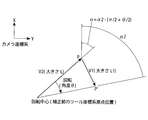
- the vector V 2 from P to the tool coordinate system origin can be obtained by the following method using the vectors V 1 and ⁇ based on FIG. 4, and therefore the tip of the output shaft 42 in the current tool coordinate system.
- synthesizing the vectors V 2 a section center position it is possible to obtain the tip center position of the precise output shaft 42.
- a vector V 1 (size L 1 , angle ⁇ 2 from the camera coordinate system X-axis) is calculated from the coordinate values of P and P ′, and the calculated value is used to calculate from the tool coordinate system origin.
- a vector V 1 (size L, angle ⁇ from the camera coordinate system X axis) toward P is obtained by the following equation.
- ⁇ ⁇ 2- ( ⁇ / 2 + ⁇ / 2)
- the vector V 1 which has been determined by the, by combining the current tool coordinate system origin position, to calculate the precise tip center position P of the output shaft 42 *.
- the above-mentioned optical sensor (distance sensor) 23 senses the edge of the motor fitting portion (circular insertion port) with high processing accuracy in the member to which the motor 41 is attached (for example, the arm member of the product robot 61). To do. At this time, the hand 3 of the work robot 2 monitors the distance sensor reading while moving from the inside to the outside, and detects the stepped portion.
- the sensing is performed in two stages of coarse sensing from the inside to the outside and detailed sensing from the outside to the inside.
- a bolt hole (a bolt for fixing the motor 41 to the target member) is formed in the target member to which the motor is attached. Measure the hole to wear, and determine the final set rotation position.
- the plane obtained in (1) is the XY plane
- the center position obtained in (2) is the insertion position
- the center position obtained in (2) is changed to the bolt hole center position detected in (3).
- a coordinate (base coordinate system) having the X direction as the X axis is generated.
- the gears can be fitted together by the work robot 2 without any trouble.
Landscapes
- Engineering & Computer Science (AREA)
- Mechanical Engineering (AREA)
- Robotics (AREA)
- General Engineering & Computer Science (AREA)
- Human Computer Interaction (AREA)
- Manipulator (AREA)
- Automatic Assembly (AREA)
- Retarders (AREA)
- Length Measuring Devices By Optical Means (AREA)
Abstract
Description
前記第2の画像処理工程が、前記第2の歯車の画像を画像処理して前記第2の歯車の領域を検出し、検出された前記第2の歯車の領域に基づき、前記第2の歯車の歯車軸の先端部の位置および根元部の位置、および前記第2の歯車の位相を取得する、ことを特徴とする。
減速機歯車の特性情報のうち、遊星歯車44内において組立後にモータ側歯車43の軸心となるべき目標位置は、すべての遊星歯車44に囲まれた領域において、すべての遊星歯車44から等距離にある点として算出し特定する。
撮像画像を二値化等その他の画像処理手段を用いて遊星歯車44の部分の輪郭線を抽出し、予め記憶しておいた遊星歯車44の形状とのパターンマッチングにより、遊星歯車44の領域の検出を行う。なお、遊星歯車44の領域は、図2において、遊星歯車44の歯型形状の境界線と挿入穴46の円弧に囲まれた部分である。
前記(1)により検出された遊星歯車44の領域に基づき、検出された領域に存在する複数の谷部分を抽出し、抽出された複数の谷部分の重心Eの位置を算出した後、それらの重心Eの位置を通る3つの円弧ai(i=1、2、3)を算出する。
前記(2)で算出された3つの円弧aiのすべてに外接する外接円bおよびその中心点Bを算出する。中心点Bが、遊星歯車44内において組立後にモータ側歯車43の軸心となるべき目標位置となる。
3つの円弧aiのうち1つの円弧を選定して、選定された円弧aiと円bの接点Dから最も近い重心Eを選択し、円bの中心点Bから重心Eの方向を算出する。モータ側歯車43の軸心を基準として、方向BEが、遊星歯車44の谷の方向であるため、モータ側歯車挿入軸穴に挿入して嵌め合わせるべきモータ側歯車の山部分の中心線(線対称である歯車の山部分の中心線)の方向であると近似することができる。これにより、遊星歯車44のモータ側歯車挿入軸穴内にモータ側歯車43を組み込む際は、モータ側歯車43の歯車の山部分の中心線方向を前記で算出した方向BEとなるように調整して挿入することができる。
作業ロボットを用いた歯車の組立作業においては、載置台上に載置されているモータ41をハンド3で把持して組立作業を行うため、作業ごとにハンド3によるモータ41の把持位置にずれが生ずる。この把持位置のずれにより、モータ41の出力軸42の先端部中心位置および軸線方向にずれが生じる。また、載置台上に載置されているモータ側歯車43の位相は任意であるため、ハンド3に把持された直後の状態においては、モータ側歯車43の位相は特定されていない。
以下、第2の画像処理部13による画像処理方法を含めて、モータ側歯車43の位相の計測および出力軸42の先端部中心位置と軸線方向のずれを計測し、その計測結果に基づき、出力軸42の軸心方向を修正する方法について、詳細に説明する。
作業ロボット2を動作させて、出力軸42の先端が第2の撮像装置22の方に向き、出力軸42の軸線が第2の撮像装置22のレンズ光軸と略一致する位置であって、第2の撮像装置22に対して少なくとも出力軸の長さよりも長い距離を離れた位置にハンド3を移動する。
まず、二値化処理その他の手法を用いて、モータ側歯車43の輪郭線を抽出し、予め記憶しておいたモータ側歯車43の形状とのパターンマッチングにより、モータ側歯車43の領域の検出を行う。その後、検出されたモータ側歯車43の領域に基づき、出力軸42の先端部中心位置Pを算出する。
前記(i)により検出されたモータ側歯車43の領域に基づき、モータ側歯車43の山部分を抽出し、特定の山部分の頂点Nを選択して、前記(i)で算出された先端部中心位置Pから選択された頂点Nに対する方向PNを生成する。この方向PNをモータ側歯車43の位相とする。
作業ロボット2を動作させて、出力軸42の軸線方向に第2の撮像装置22から離れる方向に出力軸42の長さに相当する距離だけモータ41を後退させた後、第2の撮像装置22により、出力軸42の根元部が視野範囲に含まれるように撮像する。第2の撮像装置22により取得された画像は、第2の画像処理部13へ送信され、第2の画像処理部13により二値化処理などの手法を用いて、出力軸42の根元部の輪郭線を抽出し、根元部の断面形状が円形であるという形状的特徴を利用して、出力軸42の根元部中心位置Qを算出する。
(3-1)出力軸42の先端部中心位置の計測(再計測)
モータ側歯車43を減速機歯車31に組み込む作業を作業ロボット2に行わせる場合には、減速機歯車31の挿入軸穴軸心および挿入軸穴軸心方向に対して出力軸42の先端部中心および軸心を一致させて組立ロボット2を動作制御するために、前述したツール座標系が設定されている。
作業ロボット2を動作させて、出力軸42の軸線方向に第2の撮像装置22から離れる方向に出力軸42の長さに相当する距離だけモータ41を後退させた後、第2の撮像装置22により、出力軸42の根元部が視野範囲に含まれるようにして撮像する。撮像画像を第2の画像処理部23により二値化処理などの手法を用いて、出力軸42の根元部の輪郭線を抽出し、根元部の断面形状が円形であるということを利用して、再計測された出力軸42の根元部中心位置Q’を算出する。
作業ロボット2のハンド3に把持されたモータ41をツール座標系Z軸周りに角度θ回転させた場合、回転中心であるツール座標系Z軸上に存在する点は、物理的に不変であるため、第2の撮像装置22による撮像画像における位置も同様に不変であることから、カメラ座標系(CCDカメラのCCD等の撮像面をXY面とし、撮像面の中心を原点とする座標系)においても不変である。
作業ロボット2のハンド3に把持されたモータ41をツール座標系Z軸周りに角度θ回転させると、出力軸42の先端部中心がツール座標系Z軸上に存在していないと、出力軸42の先端部中心位置のカメラ座標系のXY座標値は、図3に示すように、PからP’に移動(変位)する。カメラ座標系においてPからP’に向かう移動ベクトルをベクトルV1とすると、ベクトルV1は、P、P’の算出座標値から算出できる。
出力軸42の根元部中心位置についても、前記(i)と同様な方法により、算出座標値Q、Q’に基づき補正し、出力軸42の精密な根元部中心位置Q*を算出する。
前記(i)と(ii)で算出したP*とQ*に基づき、出力軸42の精密な軸心方向C*を算出する。
前記により算出された出力軸42の精密な根元部中心位置Q*および先端部中心位置P*、および精密な軸心方向C*に基づき、Q*をツール座標系原点、Cをツール座標系Z軸と新たなツール座標系となるように設定し直す。
本実施形態による歯車組立装置に基づくモータ側歯車43と減速機歯車の組立方法を、以下に詳細に説明する。
ハンド3がモータ41を把持していない状態で作業ロボット1を駆動して、ハンド3に装着された光学センサ(レーザ距離センサなど)23を用いて、モータ41を取り付ける平面(例えば、製品ロボット61のアーム部材の表面)の位置(ロボットベース座標系)を生成する。すなわち、光学センサ23で検出した3点を通る平面を算出し、ロボットベース座標系での平面傾き(挿入軸方向)を決定する。
モータ41を取り付ける対象の部材(例えば、製品ロボット61のアーム部材)における、加工精度の高い、モータ嵌め合い部(円形状の挿入口)のエッジを、上述の光学センサ(距離センサ)23でセンシングする。このとき、作業ロボット2のハンド3は、内側から外側に向かって移動しながら距離センサ読み値を監視し、段差部分を検出する。ここで、処理速度向上のため、内側から外側に向けて粗センシング、外側から内側に向けて詳細センシングの二段階でセンシングを実施する。
作業ロボット2に装着したCCDカメラ(第1の撮像装置21を兼用しても良い。)で、モータを取り付ける対象部材に形成されたボルト穴(モータ41を対象部材に固定するためのボルトを螺着する穴)を計測し、最終セット回転位置を決定する。
作業ロボット2のハンド3を製品ロボット61の駆動軸付近に接近させて、駆動軸に設けられたモータ31の挿入穴46から、ハンド3に装着された第1の撮像装置21により挿入穴46の内部の状況を撮像して、第1の画像処理部22を用いた画像処理により、減速機歯車31の位相並びにモータ側歯車挿入軸穴および挿入軸穴軸心の位置を算出する。
載置台上に載置されているモータ31を作業ロボット2のハンド3で把持する。ハンド3又はモータ31には位置決め用ピンが設けられているため、モータ31は、所定の精度でハンド3に把持される。
作業ロボット2のハンド3で把持したモータ31の出力軸42を第2の撮像装置で撮像し、撮像画像を第2の画像処理部23により画像処理することにより、モータ側歯車43の位相の検出および出力軸42の先端部中心位置と根元部中心位置の計測を行う。
第2の画像処理部23により算出された出力軸42の軸心方向の計測結果に基づき、ツール座標系の設定を変更する。
設定変更されたツール座標系に基づき組立ロボット2の動作制御により、モータ側歯車43が、減速機側歯車31と嵌め合わせながら歯車同士の組立が実行される。
2 作業ロボット
3 ハンド
4 ロボット制御装置
11 画像処理システム
12 第1の画像処理部
13 第2の画像処理部
21 第1の撮像装置
22 第2の撮像装置
23 光学センサ(距離センサ)
31 減速機歯車(第1の歯車)
41 モータ
42 出力軸
43 モータ側歯車(第2の歯車)
44 遊星歯車
46 挿入穴
61 製品ロボット
C 外接円bの中心
D 円弧aと外接円bとの接点
E 遊星歯車の谷部分の重心
F モータ側歯車の山部分の重心
a 遊星歯車谷部分の重心を通る円弧
b 円弧aに外接する外接円
Claims (18)
- 第1の歯車に第2の歯車を嵌め合わせて歯車機構を組み立てるための歯車機構の組立装置であって、
前記第2の歯車を保持するためのハンドを有するロボットと、
前記ハンドに設けられ、前記第1の歯車を撮像するための第1の撮像装置と、
前記第2の歯車を撮像するための第2の撮像装置と、
前記第1の撮像装置により撮像された画像を画像処理して前記第2の歯車の嵌め込み位置および前記第1の歯車の位相を取得し、前記第2の撮像装置により撮像された画像を画像処理して前記第2の歯車の位相および前記第2の歯車の歯車軸の位置を取得する画像処理システムと、を備え、
前記画像処理システムにより取得された情報に基づいて前記ロボットを制御して、前記ハンドに保持された前記第2の歯車の前記歯車軸を前記第1の歯車における前記第2の歯車の嵌め込み位置に位置合わせするとともに、前記第2の歯車の位相を前記第1の歯車の位相に位置合わせすることにより、前記ロボットを用いて前記歯車機構を組み立てるように構成されている、歯車機構の組立装置。 - 前記画像処理システムが、前記第1の歯車の画像を画像処理して前記第1の歯車の領域を検出し、検出された前記第1の歯車の領域に基づき、前記第1の歯車における前記第2の歯車の嵌め込み位置および前記第1の歯車の位相を取得する第1の画像処理手段を備えている、請求項1記載の歯車機構の組立装置。
- 前記第1の歯車は、複数の遊星歯車を有し、
前記第1の画像処理手段は、前記第1の歯車の領域に基づき、撮像画像に含まれる前記複数の遊星歯車についての谷部分を抽出し、抽出された前記谷部分の重心を円周上の点とする複数の円弧に外接する外接円の中心を前記第1の歯車における前記第2の歯車の嵌め込み位置とすると共に、前記外接円の中心を基準として、前記複数の円弧のいずれかにおける前記外接円との接点に最も近い位置にある谷部分の重心に向かう方向を前記第1の歯車の位相として特定する、請求項2記載の歯車機構の組立装置。 - 前記第1の歯車は、複数の遊星歯車を有し、
前記第1の画像処理手段は、前記第1の歯車の領域に基づき、前記第1の撮像装置の撮像画像に含まれる前記複数の遊星歯車についての谷部分を抽出し、抽出された前記谷部分の重心を円周上の点とする複数の円弧に外接する外接円の中心を前記第1の歯車における前記第2の歯車の嵌め込み位置とすると共に、前記外接円の中心を基準として、前記複数の円弧のいずれかにおける前記外接円との接点からの前記外接円上の長さが、前記円弧において前記接点に最も近い位置に存在する谷部分の重心と前記接点との間の前記円弧の円周上の長さと等しくなる前記外接円の円周上の点に向かう方向を前記第1の歯車の位相として特定する、請求項2記載の歯車機構の組立装置。 - 前記画像処理システムが、前記第2の歯車の画像を画像処理して前記第2の歯車の領域を検出し、検出された前記第2の歯車の領域に基づき、前記第2の歯車の前記歯車軸の先端部の位置および根元部の位置、および前記第2の歯車の位相を取得する第2の画像処理手段を備えている、請求項1乃至4のいずれか一項に記載の歯車機構の組立装置。
- 前記第2の画像処理手段により取得された前記第2の歯車の前記歯車軸の先端部の位置および根元部の位置に基づき、前記第2の歯車の軸心方向を取得し、前記第2の歯車の前記軸心方向に基づき、前記ハンドによる前記第2の歯車の保持位置のずれを修正するように前記ロボットを制御する、請求項5記載の歯車機構の組立装置。
- 前記第2の画像処理手段により前記第2の歯車の前記歯車軸の先端部の位置および根元部の位置を取得した後、前記ハンドを予め設定された角度回転させて、前記第2の撮像装置により前記第2の歯車を再度撮像し、再度の撮像画像に基づき前記第2の画像処理手段により前記第2の歯車の前記歯車軸の先端部の位置および根元部の位置を再度取得し、それら前後2回にわたって取得した前記第2の歯車の前記歯車軸の先端部の位置および根元部の位置に関する情報に基づき、前記第2の歯車の軸心方向を取得し、前記第2の歯車の前記軸心方向に基づき、前記ハンドによる前記第2の歯車の保持位置のずれを修正するように前記ロボットを制御する、請求項6記載の歯車機構の組立装置。
- 前記第二の歯車は、モータの出力軸に設けられており、
前記ハンドは、前記モータを把持するように構成されており、
前記モータが装着される対象物までの距離を測定するための光学センサが前記ハンドに設けられている、請求項1乃至7のいずれか一項に記載の歯車機構の組立装置。 - 前記歯車機構は、遊星歯車機構であり、前記第1の歯車が前記遊星歯車機構の遊星歯車であり、前記第2の歯車が前記遊星歯車機構の太陽歯車である、請求項1乃至8のいずれか一項に記載の歯車機構の組立装置。
- ロボットを用いて第1の歯車に第2の歯車を嵌め合わせて歯車機構を組み立てる歯車機構の組立方法であって、
前記第1の歯車における前記第2の歯車の嵌め込み位置および前記第1の歯車の位相を取得する第1の歯車計測工程と、
前記第2の歯車の位相および歯車軸の位置を取得する第2の歯車計測工程と、を備え、
前記第1の歯車計測工程および前記第2の歯車計測工程により取得された情報に基づいて前記ロボットを制御して、前記ロボットのハンドに保持されている前記第2の歯車の前記歯車軸を前記第1の歯車における前記第2の歯車の嵌め込み位置に位置合わせするとともに、前記第2の歯車の位相を前記第1の歯車の位相に位置合わせすることにより、前記ロボットを用いて前記歯車機構を組み立てる、歯車機構の組立方法。 - 前記第1の歯車計測工程が、前記ハンドに設けられた撮像装置を用いて前記第1の歯車の画像を取得して画像処理を行う第1の画像処理工程を有し、
前記第1の画像処理工程が、前記第1の歯車の画像を画像処理して前記第1の歯車の領域を検出し、検出された前記第1の歯車の領域に基づき、前記第1の歯車における前記第2の歯車の嵌め込み位置および前記第1の歯車の位相を取得するように構成されている、請求項10記載の歯車機構の組立方法。 - 前記第1の歯車は、複数の遊星歯車を有し、
前記第1の画像処理工程において、前記第1の歯車の領域に基づき、撮像画像に含まれる前記複数の遊星歯車についての谷部分を抽出し、抽出された前記谷部分の重心を円周上の点とする複数の円弧に外接する外接円の中心を前記第1の歯車における前記第2の歯車の嵌め込み位置とすると共に、前記外接円の中心を基準として、前記複数の円弧のいずれかにおける前記外接円との接点に最も近い位置にある谷部分の重心に向かう方向を前記第1の歯車の位相として特定する、請求項11記載の歯車機構の組立方法。 - 前記第1の歯車は、複数の遊星歯車を有し、
前記第1の画像処理工程において、前記第1の歯車の領域に基づき、撮像画像に含まれる前記複数の遊星歯車についての谷部分を抽出し、抽出された前記谷部分の重心を円周上の点とする複数の円弧に外接する外接円の中心を前記第1の歯車における前記第2の歯車の嵌め込み位置とすると共に、前記外接円の中心を基準として、前記複数の円弧のいずれかにおける前記外接円との接点からの外接円上の長さが、前記円弧において前記接点に最も近い位置に存在する谷部分の重心と前記接点との間の前記円弧の円周上の長さと等しくなる前記外接円の円周上の点に向かう方向を前記第1の歯車の位相として特定する、請求項11記載の歯車機構の組立方法。 - 前記第2の歯車計測工程が、前記第2の歯車の画像を取得して画像処理する第2の画像処理工程を有し、
前記第2の画像処理工程が、前記第2の歯車の画像を画像処理して前記第2の歯車の領域を検出し、検出された前記第2の歯車の領域に基づき、前記第2の歯車の歯車軸の先端部の位置および根元部の位置、および前記第2の歯車の位相を取得する、請求項10乃至13のいずれか一項に記載の歯車機構の組立方法。 - 前記第2の画像処理工程により取得された前記第2の歯車の歯車軸の先端部の位置および根元部の位置に基づき、前記第2の歯車の軸心方向を取得し、前記第2の歯車の前記軸心方向に基づき、前記ハンドによる前記第2の歯車の保持位置のずれを修正するように前記ロボットを制御する、請求項14記載の歯車機構の組立方法。
- 前記第2の歯車計測工程において前記第2の歯車の前記歯車軸の先端部の位置および根元部の位置を取得した後、前記ハンドを予め設定された角度回転させて、前記第2の歯車を再度撮像し、再度の撮像画像に基づき記第2の歯車の前記歯車軸の先端部の位置および根元部の位置を再度取得し、それら前後2回にわたって取得した前記第2の歯車の前記歯車軸の先端部の位置および根元部の位置に関する情報に基づき、前記第2の歯車の軸心方向を取得し、前記第2の歯車の前記軸心方向に基づき、前記ハンドによる前記第2の歯車の保持位置のずれを修正するように前記ロボットを制御する、請求項15記載の歯車機構の組立方法。
- 前記第二の歯車は、モータの出力軸に設けられており、
前記ハンドは、前記モータを把持するように構成されており、
前記モータが装着される対象物までの距離を、前記ハンドに設けられた光学センサによって計測し、その計測結果に基づいて前記対象物におけるベース座標系を生成する、請求項10乃至16のいずれか一項に記載の歯車機構の組立方法。 - 前記歯車機構は、遊星歯車機構であり、前記第1の歯車が前記遊星歯車機構の遊星歯車であり、前記第2の歯車が前記遊星歯車機構の太陽歯車である、請求項10乃至17のいずれか一項に記載の歯車機構の組立方法。
Priority Applications (4)
| Application Number | Priority Date | Filing Date | Title |
|---|---|---|---|
| KR1020177037067A KR102091917B1 (ko) | 2015-05-25 | 2016-05-12 | 기어 기구의 조립 장치 및 조립 방법 |
| CN201680030252.6A CN107614195B (zh) | 2015-05-25 | 2016-05-12 | 齿轮机构的组装装置及组装方法 |
| US15/577,082 US20180207755A1 (en) | 2015-05-25 | 2016-05-12 | Gear mechanism assembly apparatus and assembly method |
| DE112016002353.7T DE112016002353T5 (de) | 2015-05-25 | 2016-05-12 | Montagevorrichtung und Montageverfahren für einen Zahnradmechanismus |
Applications Claiming Priority (2)
| Application Number | Priority Date | Filing Date | Title |
|---|---|---|---|
| JP2015-105080 | 2015-05-25 | ||
| JP2015105080A JP6614805B2 (ja) | 2015-05-25 | 2015-05-25 | 歯車機構の組立装置および組立方法 |
Publications (1)
| Publication Number | Publication Date |
|---|---|
| WO2016190124A1 true WO2016190124A1 (ja) | 2016-12-01 |
Family
ID=57393991
Family Applications (1)
| Application Number | Title | Priority Date | Filing Date |
|---|---|---|---|
| PCT/JP2016/064201 Ceased WO2016190124A1 (ja) | 2015-05-25 | 2016-05-12 | 歯車機構の組立装置および組立方法 |
Country Status (7)
| Country | Link |
|---|---|
| US (1) | US20180207755A1 (ja) |
| JP (1) | JP6614805B2 (ja) |
| KR (1) | KR102091917B1 (ja) |
| CN (1) | CN107614195B (ja) |
| DE (1) | DE112016002353T5 (ja) |
| TW (1) | TWI613054B (ja) |
| WO (1) | WO2016190124A1 (ja) |
Cited By (2)
| Publication number | Priority date | Publication date | Assignee | Title |
|---|---|---|---|---|
| CN107030696A (zh) * | 2017-04-28 | 2017-08-11 | 广州瑞松北斗汽车装备有限公司 | 一种视觉引导抓手 |
| CN114211496A (zh) * | 2021-12-29 | 2022-03-22 | 中国重汽集团济南动力有限公司 | 一种基于机械臂的智能齿轮对齿自动装配系统 |
Families Citing this family (8)
| Publication number | Priority date | Publication date | Assignee | Title |
|---|---|---|---|---|
| US10773391B2 (en) * | 2017-01-17 | 2020-09-15 | Seiko Epson Corporation | Control device and robot system |
| JP7234577B2 (ja) * | 2018-10-31 | 2023-03-08 | セイコーエプソン株式会社 | ロボットシステム、ロボット制御方法、及びエンコーダー |
| CN111442742B (zh) * | 2020-04-16 | 2021-11-02 | 创新奇智(重庆)科技有限公司 | 齿轮检测设备及方法 |
| CN112658643B (zh) * | 2020-12-30 | 2022-07-01 | 中国科学院自动化研究所 | 接插件装配方法 |
| WO2022155882A1 (en) * | 2021-01-22 | 2022-07-28 | Abb Schweiz Ag | Assembling apparatus, assembling method and computer readable storage medium |
| CN113977266B (zh) * | 2021-11-16 | 2022-08-02 | 南京高速齿轮制造有限公司 | 一种行星齿轮的装配模具及其装配方法 |
| CN115890679B (zh) * | 2022-12-02 | 2024-02-13 | 西南交通大学 | 基于视觉的轨道车辆转向架枕簧缺口定位与夹持方法 |
| CN120190590B (zh) * | 2025-05-26 | 2025-08-12 | 北京康视杰智能科技有限公司 | 一种发动机大齿轮与小齿轮自动装配引导方法及系统 |
Citations (4)
| Publication number | Priority date | Publication date | Assignee | Title |
|---|---|---|---|---|
| JPH02185331A (ja) * | 1989-01-13 | 1990-07-19 | Hitachi Ltd | ギヤの自動組付方法 |
| JP2854677B2 (ja) * | 1990-06-08 | 1999-02-03 | 株式会社日立製作所 | ギヤ組付け方法およびギヤ組付け装置 |
| JP4685804B2 (ja) * | 2007-01-12 | 2011-05-18 | 本田技研工業株式会社 | ギヤ装置組立て方法および位相合わせ冶具 |
| JP2012232369A (ja) * | 2011-04-28 | 2012-11-29 | Kawasaki Heavy Ind Ltd | 部品の組立方法および部品の組立装置 |
Family Cites Families (8)
| Publication number | Priority date | Publication date | Assignee | Title |
|---|---|---|---|---|
| JP2689737B2 (ja) * | 1991-02-18 | 1997-12-10 | 株式会社日立製作所 | ギヤ自動挿入機 |
| JPH0852682A (ja) | 1994-08-10 | 1996-02-27 | Ricoh Co Ltd | ロボットハンド装置 |
| JPH1128629A (ja) * | 1997-07-10 | 1999-02-02 | Mitsubishi Automob Eng Co Ltd | ギヤ組付装置 |
| JP4768153B2 (ja) * | 2001-06-29 | 2011-09-07 | ヤマハ発動機株式会社 | 二段ギヤ組込用治具 |
| JP2003262256A (ja) * | 2002-03-08 | 2003-09-19 | Sumitomo Heavy Ind Ltd | 揺動内接噛合遊星歯車装置及びその外歯歯車の組込み方法 |
| JP2008142867A (ja) * | 2006-12-12 | 2008-06-26 | Aisin Aw Co Ltd | プラネタリギヤの組付装置及び組付方法 |
| JP5899958B2 (ja) * | 2012-01-23 | 2016-04-06 | セイコーエプソン株式会社 | ロボット制御装置、ロボット、ロボットシステムおよびロボット制御方法 |
| JP2013154447A (ja) * | 2012-01-31 | 2013-08-15 | Seiko Epson Corp | ロボット装置およびロボット制御方法 |
-
2015
- 2015-05-25 JP JP2015105080A patent/JP6614805B2/ja not_active Expired - Fee Related
-
2016
- 2016-05-12 KR KR1020177037067A patent/KR102091917B1/ko active Active
- 2016-05-12 DE DE112016002353.7T patent/DE112016002353T5/de not_active Withdrawn
- 2016-05-12 WO PCT/JP2016/064201 patent/WO2016190124A1/ja not_active Ceased
- 2016-05-12 CN CN201680030252.6A patent/CN107614195B/zh not_active Expired - Fee Related
- 2016-05-12 US US15/577,082 patent/US20180207755A1/en not_active Abandoned
- 2016-05-25 TW TW105116311A patent/TWI613054B/zh active
Patent Citations (4)
| Publication number | Priority date | Publication date | Assignee | Title |
|---|---|---|---|---|
| JPH02185331A (ja) * | 1989-01-13 | 1990-07-19 | Hitachi Ltd | ギヤの自動組付方法 |
| JP2854677B2 (ja) * | 1990-06-08 | 1999-02-03 | 株式会社日立製作所 | ギヤ組付け方法およびギヤ組付け装置 |
| JP4685804B2 (ja) * | 2007-01-12 | 2011-05-18 | 本田技研工業株式会社 | ギヤ装置組立て方法および位相合わせ冶具 |
| JP2012232369A (ja) * | 2011-04-28 | 2012-11-29 | Kawasaki Heavy Ind Ltd | 部品の組立方法および部品の組立装置 |
Cited By (3)
| Publication number | Priority date | Publication date | Assignee | Title |
|---|---|---|---|---|
| CN107030696A (zh) * | 2017-04-28 | 2017-08-11 | 广州瑞松北斗汽车装备有限公司 | 一种视觉引导抓手 |
| CN114211496A (zh) * | 2021-12-29 | 2022-03-22 | 中国重汽集团济南动力有限公司 | 一种基于机械臂的智能齿轮对齿自动装配系统 |
| CN114211496B (zh) * | 2021-12-29 | 2023-10-10 | 中国重汽集团济南动力有限公司 | 一种基于机械臂的智能齿轮对齿自动装配系统 |
Also Published As
| Publication number | Publication date |
|---|---|
| JP6614805B2 (ja) | 2019-12-04 |
| US20180207755A1 (en) | 2018-07-26 |
| TWI613054B (zh) | 2018-02-01 |
| JP2016215345A (ja) | 2016-12-22 |
| DE112016002353T5 (de) | 2018-02-15 |
| KR102091917B1 (ko) | 2020-03-20 |
| KR20180012789A (ko) | 2018-02-06 |
| CN107614195A (zh) | 2018-01-19 |
| TW201703952A (zh) | 2017-02-01 |
| CN107614195B (zh) | 2020-10-27 |
Similar Documents
| Publication | Publication Date | Title |
|---|---|---|
| JP6614805B2 (ja) | 歯車機構の組立装置および組立方法 | |
| JP6966582B2 (ja) | ロボットモーション用のビジョンシステムの自動ハンドアイ校正のためのシステム及び方法 | |
| JP3946711B2 (ja) | ロボットシステム | |
| CN111185901B (zh) | 机器人装置 | |
| JP7153085B2 (ja) | ロボットキャリブレーションシステム及びロボットキャリブレーション方法 | |
| US9517560B2 (en) | Robot system and calibration method of the robot system | |
| US7532949B2 (en) | Measuring system | |
| CN109834710B (zh) | 机器人和机器人系统 | |
| US20160279800A1 (en) | Robot, robot control device, and robotic system | |
| CN107192331A (zh) | 一种基于双目视觉的工件抓取方法 | |
| CN110276799B (zh) | 一种坐标标定方法、标定系统及机械臂 | |
| CN112621742B (zh) | 机器人、测量用夹具以及确定工具前端位置的方法 | |
| CN106217372A (zh) | 机器人、机器人控制装置以及机器人系统 | |
| JP5618770B2 (ja) | ロボットの校正装置および校正方法 | |
| CN105313127A (zh) | 机器人、机器人的控制方法以及机器人的控制装置 | |
| JP2015136770A (ja) | 視覚センサのデータ作成システム及び検出シミュレーションシステム | |
| JPWO2018092243A1 (ja) | 作業位置補正方法および作業ロボット | |
| JP2010274381A (ja) | ビス締め装置 | |
| JP5483554B2 (ja) | ツール座標系の較正装置及び較正方法 | |
| CN114571199A (zh) | 一种锁螺丝机及螺丝定位方法 | |
| TWI918775B (zh) | 圖像處理系統及圖像處理方法 | |
| JP7510514B2 (ja) | オフセット値設定方法およびロボット制御装置 | |
| TW202219458A (zh) | 工具機的轉動軸中心位置量測方法 | |
| CN110977950B (zh) | 一种机器人抓取定位方法 | |
| CN105479469A (zh) | 用于自动机械的正交定位装置、系统和方法 |
Legal Events
| Date | Code | Title | Description |
|---|---|---|---|
| 121 | Ep: the epo has been informed by wipo that ep was designated in this application |
Ref document number: 16799832 Country of ref document: EP Kind code of ref document: A1 |
|
| WWE | Wipo information: entry into national phase |
Ref document number: 15577082 Country of ref document: US Ref document number: 112016002353 Country of ref document: DE |
|
| ENP | Entry into the national phase |
Ref document number: 20177037067 Country of ref document: KR Kind code of ref document: A |
|
| 122 | Ep: pct application non-entry in european phase |
Ref document number: 16799832 Country of ref document: EP Kind code of ref document: A1 |