WO2016189927A1 - 空調制御システム、空調制御装置、空調制御方法および空調制御プログラム - Google Patents
空調制御システム、空調制御装置、空調制御方法および空調制御プログラム Download PDFInfo
- Publication number
- WO2016189927A1 WO2016189927A1 PCT/JP2016/057571 JP2016057571W WO2016189927A1 WO 2016189927 A1 WO2016189927 A1 WO 2016189927A1 JP 2016057571 W JP2016057571 W JP 2016057571W WO 2016189927 A1 WO2016189927 A1 WO 2016189927A1
- Authority
- WO
- WIPO (PCT)
- Prior art keywords
- air
- temperature
- outdoor
- humidity
- conditioning control
- Prior art date
- Legal status (The legal status is an assumption and is not a legal conclusion. Google has not performed a legal analysis and makes no representation as to the accuracy of the status listed.)
- Ceased
Links
Images



Classifications
-
- F—MECHANICAL ENGINEERING; LIGHTING; HEATING; WEAPONS; BLASTING
- F24—HEATING; RANGES; VENTILATING
- F24F—AIR-CONDITIONING; AIR-HUMIDIFICATION; VENTILATION; USE OF AIR CURRENTS FOR SCREENING
- F24F11/00—Control or safety arrangements
- F24F11/89—Arrangement or mounting of control or safety devices
-
- Y—GENERAL TAGGING OF NEW TECHNOLOGICAL DEVELOPMENTS; GENERAL TAGGING OF CROSS-SECTIONAL TECHNOLOGIES SPANNING OVER SEVERAL SECTIONS OF THE IPC; TECHNICAL SUBJECTS COVERED BY FORMER USPC CROSS-REFERENCE ART COLLECTIONS [XRACs] AND DIGESTS
- Y02—TECHNOLOGIES OR APPLICATIONS FOR MITIGATION OR ADAPTATION AGAINST CLIMATE CHANGE
- Y02B—CLIMATE CHANGE MITIGATION TECHNOLOGIES RELATED TO BUILDINGS, e.g. HOUSING, HOUSE APPLIANCES OR RELATED END-USER APPLICATIONS
- Y02B30/00—Energy efficient heating, ventilation or air conditioning [HVAC]
- Y02B30/70—Efficient control or regulation technologies, e.g. for control of refrigerant flow, motor or heating
Definitions
- Embodiments of the present invention relate to an air conditioning control system, an air conditioning control device, an air conditioning control method, and an air conditioning control program.
- an air conditioning control system that takes in outdoor air into the room and adjusts the state of the room air.
- the air conditioning control system detects indoor and outdoor air conditions such as outdoor air temperature and humidity, indoor air temperature and humidity, and determines whether to take outdoor air into the room based on the detected indoor and outdoor air conditions. , And the amount of outdoor air intake was controlled.
- the air-conditioning control system does not control the outdoor environment with sufficient consideration, there is a possibility that a substance that should not be taken into the room may be taken into the room.
- the problem to be solved by the present invention is to provide an air-conditioning control system, an air-conditioning control device, an air-conditioning control method, and an air-conditioning control program capable of suppressing the introduction of substances that should not be taken into the room.
- the air conditioning control system of the embodiment includes a first inside air detection unit, a first outside air detection unit, a second inside air detection unit, a second outside air detection unit, a first determination unit, and a second It has a determination part and a determination part.
- the first inside air detection unit detects the temperature and humidity of room air in the predetermined space.
- the first outside air detection unit detects the temperature and humidity of outdoor air outside the predetermined space.
- the second room air detector detects a contaminant in the room air.
- the second outside air detection unit detects a contaminant in the outdoor air.
- the first determination unit compares the temperature and humidity detected by the first inside air detection unit with the temperature and humidity detected by the first outside air detection unit, and sets the outdoor air in the predetermined space. Judge whether to incorporate.
- the determination unit determines whether or not to take in the outdoor air into the predetermined space based on the result determined by the first determination unit and the result determined by the second determination unit.
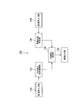
- the block diagram which shows the structure of 100 A of air-conditioning control parts in 2nd Embodiment. 9 is a flowchart illustrating an example of a flow for notifying a decrease in the removal efficiency of contaminants in the second embodiment.
- FIG. 1 is a block diagram showing a configuration of an air conditioning control system 1 in the first embodiment.
- the air conditioning control system 1 controls the air state in a predetermined space.
- the predetermined space is a space in which the air condition is controlled by the air conditioning control system 1.
- the predetermined space is, for example, one indoor space in a house where the user lives.
- the air conditioning control system 1 includes an air conditioning control device 10.
- the air conditioning control device 10 includes an air conditioning control unit 100, an indoor air introduction port 102, and a conditioned air discharge port 104.
- the air conditioning control device 10 includes a temperature / humidity sensor 106 for room air and a pollutant sensor 108 for room air.
- the air conditioning control device 10 is connected to an outside air duct 110.
- the outdoor air duct 110 is connected to an outdoor air introduction port 112 through which outdoor air is introduced.
- the outdoor air duct 110 is provided with an outdoor air temperature / humidity sensor 114 and an outdoor air contaminant sensor 116.
- the air conditioning control unit 100 comprehensively controls each unit in the air conditioning control system 1. Thereby, the air-conditioning control part 100 controls the state of the air in a predetermined space.
- the air-conditioning control apparatus 10 can implement a function described later on a controller in, for example, a HEMS (Home Energy Management System) or a BEMS (Building Energy Management System).
- Each unit in the air conditioning control unit 100 is a software function unit that functions when a processor such as a CPU (Central Processing Unit) executes a program stored in a storage unit (not shown).
- the air conditioning control unit 100 may be a hardware function unit such as an LSI (Large Scale Integration) or an ASIC (Application Specific Integrated Circuit).
- air in the predetermined space (room air) is introduced.
- the temperature and humidity of the indoor air introduced into the indoor air inlet 102 are adjusted by an air conditioner such as a heat exchanger (not shown).
- the conditioned air whose temperature and humidity are adjusted by the air conditioning equipment is discharged from the conditioned air discharge port 104 to a predetermined space.
- the temperature value and humidity value of the indoor air introduced into the indoor air inlet 102 are detected by the indoor air temperature / humidity sensor 106.
- the temperature value and humidity value of the room air are output to the air conditioning control unit 100 by the room air temperature / humidity sensor 106.
- the indoor air introduced into the indoor air inlet 102 is detected by the indoor air contaminant sensor 108.
- the indoor air pollutant sensor 108 outputs a signal having a value corresponding to the concentration of the pollutant in the indoor air to the air conditioning control unit 100.
- the outdoor air inlet 112 is connected to an outdoor unit (not shown) that exchanges heat by sucking air outside the predetermined space (outdoor air).
- the outdoor air introduced into the outdoor air introduction port 112 is supplied to the air conditioning control device 10 via the outdoor air duct 110.
- the outside air duct 110 is provided with a contaminant removal filter 110a that removes contaminants in the outdoor air.
- the pollutant removal filter 110a showed an example provided in the duct 110 for external air, you may provide in other places into which outdoor air, such as the outdoor air inlet 112, is introduce
- the outdoor air taken in by the air conditioning control device 10 is adjusted in temperature and humidity by air conditioning equipment such as a heat exchanger (not shown).
- the conditioned air whose temperature and humidity are adjusted by the air conditioning equipment is discharged from the conditioned air discharge port 104 to a predetermined space.
- the outdoor air temperature / humidity sensor 114 detects the temperature value and the humidity value of the outdoor air introduced into the outdoor air duct 110.
- an example of detecting the temperature value and the humidity value of the outdoor air introduced into the outdoor air duct 110 has been shown, but many outdoor air temperature / humidity sensors are generally employed. It may be installed outside such a building, and the temperature value and humidity value of outdoor air may be detected.
- the temperature value and humidity value of the outdoor air are output to the air conditioning control unit 100 by the outdoor air temperature / humidity sensor 114.
- the outdoor air introduced into the outdoor air duct 110 is detected by the outdoor air contaminant sensor 116.
- the outdoor air pollutant sensor 116 outputs a signal having a value corresponding to the concentration of the pollutant in the outdoor air to the air conditioning control unit 100.
- the state of outdoor air is acquired by the air-conditioning control apparatus 10 via a network, and is output to the air-conditioning control part 100. Also good.
- FIG. 2 is a block diagram illustrating a functional configuration of the air conditioning control unit 100 according to the first embodiment.
- the air conditioning control unit 100 includes a first signal input unit 120, an outside air intake condition calculation unit 122, a second signal input unit 124, an environmental state determination unit 126, an outside air intake determination unit 128, and a control output unit 130. With.
- the first signal input unit 120 is connected to the indoor air temperature / humidity sensor 106 and the outdoor air temperature / humidity sensor 114.
- the first signal input unit 120 detects a temperature / humidity state included in the room air (a first room air detection unit).
- the 1st signal input part 120 detects the temperature / humidity state contained in outdoor air (1st outdoor air detection part).
- the first signal input unit 120 inputs the temperature value and humidity value of the indoor air and the temperature value and humidity value of the outdoor air, and supplies them to the outdoor air intake condition calculation unit 122.
- the outdoor air intake condition calculation unit 122 compares the temperature / humidity state of the indoor air with the temperature / humidity state of the outdoor air, and determines whether or not the outdoor air is taken into the predetermined space (first determination unit).
- the result determined by the outside air intake condition calculation unit 122 is a condition (outside air intake condition) for determining whether to take in outdoor air.
- the outdoor air intake condition calculation unit 122 calculates the enthalpy using the temperature and humidity state of the indoor air and the temperature and humidity state of the outdoor air.
- Enthalpy is calculated according to Equation 1 below.
- h Ca * t + x (Cv * t + r0) (Formula 1)
- h is enthalpy and is represented by J / kg [kcal / kg].
- Ca is the constant pressure specific heat of dry air, and is expressed as 1005 J / Kg ⁇ K and 0.240 [kcal / kg ⁇ ° C.].
- Cv is the constant-pressure specific heat of water vapor, and is expressed as 1846 [J / kg ⁇ K] and 0.441 [kcal / kg ⁇ ° C.].
- r0 is the latent heat of vaporization of water at 0 ° C., and is expressed as 2501 ⁇ 103 [J / kg] and 597.5 [kcal / kg].
- t is the dry bulb temperature (air temperature) [° C.].
- x is absolute humidity [kg / kg].
- the absolute humidity x is calculated using the water vapor partial pressure Pw according to the following equation 2.
- x 0.602198 ⁇ Pw / (101.325-Pw) (Formula 2)
- the water vapor partial pressure Pw is calculated by the following formula 4 obtained by modifying the following formula 3 using the relative humidity ⁇ [%] and the saturated water vapor partial pressure Pws [kPa (mmHg)].
- ⁇ Pw / Pws ⁇ 100 (Formula 3)
- Pw ( ⁇ ⁇ Pws) / 100 (Formula 4)
- Pws in the above equation 4 is expressed as the following equation 5.
- T is the absolute temperature [K]
- T is the dry bulb temperature t + 273.15.
- the outside air intake condition calculation unit 122 converts the temperature value of the room air input by the first signal input unit 120 into the dry bulb temperature t for obtaining the dry bulb temperature t in the above equation 1 and the absolute temperature T in the above equation 5. Substituting the humidity value of the room air input by the first signal input unit 120 into the relative humidity x in the above equation 1 and the relative humidity ⁇ in the above equation 4. Thereby, the outside air intake condition calculation unit 122 calculates the indoor enthalpy as the state of the indoor air. Further, the outside air intake condition calculation unit 122 uses the temperature value of the outdoor air input by the first signal input unit 120 as the dry bulb temperature for obtaining the dry bulb temperature t in Equation 1 and the absolute temperature K in Equation 5 above.
- the humidity value of the outdoor air input by the first signal input unit 120 is substituted into the relative humidity x in Equation 1 and the relative humidity ⁇ in Equation 4.
- the outside air intake condition calculation unit 122 calculates the outdoor enthalpy as the state of the outdoor air.
- the second signal input unit 124 detects the state of pollutants in the room air (second indoor air detection unit).
- the second signal input unit 124 detects the state of contaminants in the outdoor air (second outdoor air detection unit).
- the second signal input unit 124 is connected to the indoor air contaminant sensor 108 and the outdoor air contaminant sensor 116.
- the second signal input unit 124 inputs a signal value representing the state of pollutants in the indoor air and a signal value representing the state of pollutants in the outdoor air, and supplies them to the environmental state determination unit 126.
- the second signal input unit 124 inputs, for example, the concentration of the contaminant as the state of the contaminant.
- a pollutant is a substance that adversely affects the human body when taken into the body. Contaminants include, for example, sulfur oxide (SOx) generated when fossil fuel burns, nitrogen oxide (NOx) generated by burning fuel, and photochemical oxidant (Ox) generated when nitrogen oxide causes a photochemical reaction. ), Particulate matter (PM) such as vehicle exhaust gas and dust, suspended particulate matter (SPM) having a particle size below a predetermined value among particulate matter, and finer particulate matter having a smaller particle size such as PM2.5 It is a substance.
- the pollutant may be a chemical substance generated indoors.
- Examples of chemical substances generated indoors include volatile organic compounds produced from building materials or furniture preservatives, and organic solvents such as formaldehyde contained in adhesives or paints.
- organic solvents such as formaldehyde contained in adhesives or paints.
- the environmental state determination unit 126 determines whether or not outdoor air is taken into the predetermined space (second determination). Part). The environmental state determination unit 126 determines an environmental state related to the pollutant by taking outdoor air into the predetermined space by the determination process. The environmental state determination unit 126 supplies the determination result to the outside air intake determination unit 128.
- the outside air intake determination unit 128 determines whether to take outdoor air into the predetermined space based on the result determined by the outside air intake condition calculation unit 122 and the result determined by the environmental state determination unit 126 (decision). Part). The outside air intake determination unit 128 determines that either the result determined by the outside air intake condition calculation unit 122 or the result determined by the environment state determination unit 126 does not take outdoor air into the predetermined space. Determines not to take outdoor air into the predetermined space. The outdoor air intake determination unit 128 determines that both the result determined by the outdoor air intake condition calculation unit 122 and the result determined by the environmental state determination unit 126 are determined to take outdoor air into the predetermined space. The outdoor air is determined to be taken into the predetermined space.
- the control output unit 130 performs control for taking in outdoor air via the outdoor air introduction port 112 when the outdoor air intake determining unit 128 determines to take outdoor air into the predetermined space.
- the control output unit 130 drives, for example, an intake fan (not shown) provided in the outdoor air inlet 112 to take outdoor air into the outdoor air inlet 112 and the outdoor air duct 110.
- the control output unit 130 does not perform control for taking in outdoor air when the outdoor air intake determining unit 128 determines not to take outdoor air into the predetermined space.
- FIG. 3 is a flowchart showing the operation of the air conditioning control system 1 in the first embodiment.
- the air conditioning control unit 100 determines whether or not the control start condition is satisfied every predetermined time when the air conditioning control unit 100 is activated (step S100). The air conditioning control unit 100 repeats the determination in step S100 when the control start condition is not satisfied. When the control start condition is satisfied, the air conditioning control unit 100 performs an operation for controlling the state of the room air (step S102). The air conditioning control unit 100 determines whether or not the control continuation condition is satisfied for each predetermined period when controlling the state of the room air (step S104). The air conditioning control unit 100 continues the control of the indoor air state when the control continuation condition is satisfied.
- step S106 the air conditioning control unit 100 determines whether or not the control end condition is satisfied.
- the air-conditioning control unit 100 ends the processing when the activation state of the air-conditioning control device 10 of the air-conditioning control device 10 is off and does not satisfy the operation continuation condition, and ends the process, and satisfies the control termination condition If not, the process returns to step S100.
- FIG. 4 is a flowchart illustrating an example of a flow for controlling the state of room air in the first embodiment.
- the following description corresponds to the operations in steps S100 and S104 described above.
- the air conditioning control unit 100 determines whether or not the air conditioning control device 10 satisfies the operating condition (step S110).
- the air conditioning control unit 100 determines, as operation conditions, whether the activation state of the air conditioning control device 10 is on and whether the operation mode of the air conditioning control device 10 is cooling. If it is determined that the activation state of the air conditioning control device 10 is on and the operation mode of the air conditioning control device 10 is cooling, the air conditioning control unit 100 advances the process to step S112.
- the air-conditioning control unit 100 stops the operation of the air-conditioning control device 10 when the activation state of the air-conditioning control device 10 is on and the operation condition of the air-conditioning control device 10 is cooling is not satisfied. Then, the process ends (step S124).
- the air conditioning control unit 100 inputs the sensor signals detected by the temperature / humidity sensor 106 for indoor air and the temperature / humidity sensor 114 for outdoor air by the first signal input unit 120, and the room air by the second signal input unit 124.
- Sensor signals detected by the indoor pollutant sensor 108 and the outdoor air pollutant sensor 116 are input (step S112).
- the air conditioning control unit 100 determines whether or not the temperature / humidity condition is satisfied based on the sensor signal detected in step S112 by the outside air intake determination unit 128 (step S114).
- the temperature and humidity conditions are conditions of temperature and humidity at which outdoor air is taken in by the air conditioning control device 10 and the state of the indoor air can be controlled.
- the temperature and humidity conditions are, for example, that the temperature of the outdoor air is higher than a predetermined outdoor air cooling minimum temperature, the temperature of the indoor air is lower than the upper limit temperature of the indoor air, and the relative humidity of the indoor air is the humidity of the indoor air Three conditions of lower than the upper limit value are included.
- the minimum temperature at which outdoor air can be cooled and the humidity upper limit value of indoor air are values set in advance in the outdoor air intake determination unit 128.
- the outdoor air intake condition calculation unit 122 calculates the enthalpy of indoor air and the outdoor air based on the sensor signal detected in step S112 (step S116).
- the outside air intake determination unit 128 determines whether the enthalpy of room air (room E) is higher than a value obtained by adding a predetermined enthalpy difference ⁇ to the enthalpy of room air (outside air E).
- the predetermined enthalpy difference ⁇ is a difference between the enthalpy of the room air and the enthalpy of the room air set in order to start control of the state of the room air in step S100.
- the predetermined enthalpy difference ⁇ is a difference between the enthalpy of the room air and the enthalpy of the room air set in step S104 to continue the control of the state of the room air.
- the difference ⁇ of the enthalpy of the room air with respect to the enthalpy of the outdoor air set for starting or continuing the control of the state of the room air is a preset value.
- the outside air intake determination unit 128 advances the process to step S118. If the enthalpy of the room air is not higher than the value obtained by adding the predetermined enthalpy difference ⁇ to the enthalpy of the outdoor air, the outside air intake determination unit 128 stops the operation and ends the process (step S124).
- the outdoor air intake determination unit 128 determines whether or not the concentration of contaminants in the outdoor air and indoor air is lower than a predetermined threshold based on the sensor signal detected in step S112 (step S120).
- Two predetermined threshold values are set: a first threshold value that is compared with the concentration of the pollutant in the outdoor air, and a second threshold value that is compared with the concentration of the pollutant in the indoor air.
- the first threshold value and the second threshold value are values that suppress the influence on the human body when outdoor air is taken into the predetermined space.
- the first threshold value and the second threshold value may be preset values or values calculated based on a parameter including the concentration of the contaminant.
- the outdoor air intake determination unit 128 takes in outdoor air and An operation for controlling the air state is executed (started or continued) (step S122).
- the outdoor air intake determination unit 128 takes the outdoor air into the air conditioning control device 10 through the outdoor air inlet 112 by the control output unit 130 and controls the state of the indoor air with the conditioned air.
- the outdoor air intake determination unit 128 does not satisfy one of the two conditions that the concentration of the contaminant in the outdoor air is lower than the first threshold and the concentration of the contaminant in the indoor air is lower than the second threshold.
- step S124 the operation is stopped and the process is terminated.
- the air-conditioning control apparatus 10 can perform the determination in step S100 by setting the predetermined enthalpy difference ⁇ as the enthalpy difference for starting control in step S118. That is, the air-conditioning control apparatus 10 can start control of room air in step S102 by executing control of room air in step S122. Moreover, the air-conditioning control apparatus 10 can perform the determination in step S104 by setting the predetermined enthalpy difference ⁇ as the enthalpy difference for continuing control in step S118. That is, the air-conditioning control apparatus 10 can continue control of room air in step S102 by executing control of room air in step S122. Furthermore, the air-conditioning control apparatus 10 can execute the determination in step S106 by setting the predetermined enthalpy difference ⁇ in step S118 as the enthalpy difference for continuing control and stopping the operation in step S124. .
- the air-conditioning control apparatus 10 is higher in the enthalpy of the indoor air than the value obtained by adding the enthalpy difference for starting control to the enthalpy of the outdoor air, and the concentration of the pollutant in the outdoor air is predetermined.
- the threshold value it is determined that the condition for starting control or continuing control is satisfied, and the state of indoor air can be controlled by taking in outdoor air. Therefore, according to the air-conditioning control device 10, it is possible to suppress the introduction of substances that should not be taken into the room.
- the air conditioning control device 10 determines the concentration of the pollutant in the outdoor air and the concentration of the pollutant in the indoor air by the environmental state determination unit 126. In comparison, it may be determined whether outdoor air is taken into the predetermined space. For example, the environmental state determination unit 126 determines the outdoor air when the concentration of the pollutant peculiar to the indoor air is higher than a predetermined threshold (third predetermined value) even if the contaminant exists in the outdoor air. You may determine with taking in in predetermined space.
- FIG. 5 is a block diagram illustrating a configuration of an air conditioning control unit 100A according to the second embodiment.
- the air conditioning control unit 100A according to the second embodiment includes an indoor concentration calculation unit 140, a removal efficiency determination unit 142, and a state notification unit 144 with respect to the air conditioning control unit 100 according to the first embodiment illustrated in FIG. Prepare.
- the indoor concentration calculation unit 140 samples the concentration of the pollutant in the indoor air and the concentration of the pollutant in the outdoor air input by the second signal input unit 124 at predetermined intervals.
- the predetermined interval is set to a time during which the air conditioning control device 10 monitors the concentration of contaminants in the indoor air.
- the predetermined interval is, for example, 1 minute.
- the indoor concentration calculation unit 140 calculates the concentration of the pollutant in the outdoor air based on the concentration of the pollutant detected at the first timing and the pollutant concentration detected at the second timing. Calculate the amount of increase and the amount of increase in the concentration of pollutants in the room air. The indoor concentration calculation unit 140 calculates an average increase amount at a constant interval such as a predetermined interval for sampling, for example.
- the removal efficiency determination unit 142 calculates the contaminant removal efficiency in the contaminant removal filter 110a based on the increase amount of the contaminant concentration in the outdoor air and the increase amount of the contaminant concentration in the indoor air. For example, the removal efficiency determination unit 142 performs a calculation such that the contaminant removal efficiency in the contaminant removal filter 110a is lowered when the concentration of the contaminant in the outdoor air rapidly increases. Based on the removal efficiency calculated by the indoor concentration calculation unit 140, the removal efficiency determination unit 142 determines whether or not the contaminant removal efficiency in the contaminant removal filter 110a is reduced.
- the removal notification unit 144 notifies the state notification unit 144 of the decrease in removal efficiency. If the removal efficiency determination unit 142 determines that the contaminant removal efficiency in the contaminant removal filter 110a has not been reduced, the state notification unit 144 does not cause the removal of the reduction efficiency.
- FIG. 6 is a flowchart illustrating an example of a flow for notifying a decrease in the removal efficiency of contaminants in the second embodiment.
- the indoor concentration calculation unit 140 inputs the concentration of the pollutant in the indoor air and the concentration of the pollutant in the outdoor air as sensor signals from the second signal input unit 124 (step S130).
- the indoor concentration calculation unit 140 accumulates the input contaminant concentration in the indoor air and the contaminants in the outdoor air in a storage unit (not shown).
- the indoor concentration calculation unit 140 determines whether or not a predetermined sampling time has elapsed (step S132). When the predetermined sampling time has not elapsed, the indoor concentration calculation unit 140 continues to accumulate the contaminant concentration in the indoor air and the contaminant in the outdoor air.
- the indoor concentration calculation unit 140 determines that the predetermined sampling time has elapsed, the increase in the concentration of the pollutant in the indoor air during the predetermined sampling time and the concentration of the pollutant in the outdoor air during the predetermined sampling time. The amount of increase is calculated. Then, the removal efficiency determination unit 142 calculates the contaminant removal efficiency in the contaminant removal filter 110a based on the increase amount of the contaminant concentration in the indoor air and the increase amount of the contaminant concentration in the outdoor air (step S134). ).
- the removal efficiency determination unit 142 compares the calculated contaminant removal efficiency with a threshold value, and determines whether or not the calculated contaminant removal efficiency is below the threshold value.
- the threshold value is set to notify that the contaminant removal efficiency has decreased.
- the threshold value may be a pollutant removal efficiency set in advance in the pollutant removal filter 110a, or may be a value based on a change in pollutant removal efficiency such as a decrease rate of the pollutant removal efficiency. .
- the removal efficiency determination unit 142 causes the state notification unit 144 to notify the contaminant removal efficiency.
- the removal efficiency determination unit 142 may stop the intake of outdoor air by the outside air intake determination unit 128 when it is determined that the contaminant removal efficiency in the contaminant removal filter 110a is reduced.
- the state notification unit 144 notifies that the contaminant removal efficiency in the contaminant removal filter 110a is reduced.
- the notification destination of the state notification unit 144 may be a resident in a predetermined space, a manager of a monitoring system such as HEMS or BEMS, or a maintenance company of a house or building.
- the status notification unit 144 notifies a decrease in the removal efficiency of contaminants in the form of voice, display, or communication.
- the state notification unit 144 outputs, for example, an audio display or image display of a decrease in the removal efficiency of the pollutant by an HEMS information presentation device.
- the status notification unit 144 transmits information for notifying the computer of the monitoring system such as HEMS or BEMS of a decrease in the removal efficiency of pollutants, for example, in a mail format.
- the outdoor air intake condition calculation unit 122 that compares the temperature / humidity state of the indoor air with the temperature / humidity state of the outdoor air and determines whether to take in outdoor air
- Environmental state determination unit 126 that determines whether to take in outdoor air based on the state of pollutants in the air and the state of pollutants in the outdoor air, the result determined by the outdoor air intake condition calculation unit 122, and the environmental state
Landscapes
- Engineering & Computer Science (AREA)
- Chemical & Material Sciences (AREA)
- Combustion & Propulsion (AREA)
- Mechanical Engineering (AREA)
- General Engineering & Computer Science (AREA)
- Air Conditioning Control Device (AREA)
Abstract
実施形態の空調制御システムは、第1の判定部と、第2の判定部と、決定部とを持つ。第1の判定部は、室内空気の温湿度状態と室外空気の温湿度状態とを比較して、室外空気を取り入れるか否かを判定する。第2の判定部は、室内空気の汚染物質の状態および室外空気の汚染物質の状態に基づいて、室外空気を取り入れるか否かを判定する。決定部は、第1の判定部により判定された結果と、第2の判定部により判定された結果とに基づいて室外空気を取り入れるか否かを決定する。
Description
本発明の実施形態は、空調制御システム、空調制御装置、空調制御方法および空調制御プログラムに関する。
従来、室外空気を室内に取り込んで室内空気の状態を調整する空調制御システムが知られている。空調制御システムは、室外空気の温度および湿度、室内空気の温度および湿度などの室内外の空気状態を検出し、検出した室内外の空気状態に基づいて室内に室外空気を取り入れるか否かの判定、および室外空気の取り入れ量の制御を行っていた。しかしながら、空調制御システムは、室外における環境を十分に考慮して制御を行っていないので、室内に取り入れるべきでない物質を室内に取り入れてしまう可能性があった。
本発明が解決しようとする課題は、室内に取り入れるべきでない物質を室内に取り入れることを抑制することができる空調制御システム、空調制御装置、空調制御方法および空調制御プログラムを提供することである。
実施形態の空調制御システムは、第1の内気検知部と、第1の外気検知部と、第2の内気検知部と、第2の外気検知部と、第1の判定部と、第2の判定部と、決定部とを持つ。第1の内気検知部は、所定空間内の室内空気の温度および湿度を検知する。第1の外気検知部は、前記所定空間外の室外空気の温度および湿度を検知する。第2の内気検知部は、前記室内空気の汚染物質を検知する。第2の外気検知部は、前記室外空気の汚染物質を検知する。第1の判定部は、前記第1の内気検知部により検知された温度および湿度と前記第1の外気検知部により検知された温度および湿度とを比較して、前記所定空間に前記室外空気を取り入れるか否かを判定する。第2の判定部は、前記第2の内気検知部により検知された汚染物質および前記第2の外気検知部により検知された汚染物質に基づいて、前記所定空間に前記室外空気を取り入れるか否かを判定する。決定部は、前記第1の判定部により判定された結果と、前記第2の判定部により判定された結果とに基づいて、前記所定空間に前記室外空気を取り入れるか否かを決定する。
以下、実施形態の空調制御システム、空調制御装置、空調制御方法および空調制御プログラムを、図面を参照して説明する。
(第1の実施形態)
図1は、第1の実施形態における空調制御システム1の構成を示すブロック図である。空調制御システム1は、所定の空間における空気状態を制御する。所定の空間は、空調制御システム1により空気の状態が制御される空間である。所定の空間は、例えば、ユーザが住む住宅における一つの室内空間である。
(第1の実施形態)
図1は、第1の実施形態における空調制御システム1の構成を示すブロック図である。空調制御システム1は、所定の空間における空気状態を制御する。所定の空間は、空調制御システム1により空気の状態が制御される空間である。所定の空間は、例えば、ユーザが住む住宅における一つの室内空間である。
空調制御システム1は、空調制御装置10を備える。空調制御装置10は、空調制御部100と、室内空気導入口102と、調和空気排出口104とを備える。また、空調制御装置10は、室内空気用温度・湿度センサ106と、室内空気用汚染物質センサ108とを備える。空調制御装置10には、外気用ダクト110と接続される。外気用ダクト110は、室外空気が導入される室外空気導入口112が接続される。外気用ダクト110には、室外空気用温度・湿度センサ114と、室外空気用汚染物質センサ116とが設けられる。
空調制御部100は、空調制御システム1における各部を統括的に制御する。これにより、空調制御部100は、所定の空間における空気の状態を制御する。空調制御装置10は、例えばHEMS(Home Energy Management System)またはBEMS(Building Energy Management System)におけるコントローラに後述する機能を実装することができる。空調制御部100における各部は、例えば、CPU(Central Processing Unit)などのプロセッサが記憶部(不図示)に記憶されているプログラムを実行することによって機能するソフトウェア機能部である。また、空調制御部100は、LSI(Large Scale Integration)やASIC(Application Specific Integrated Circuit)等のハードウェア機能部であってよい。
室内空気導入口102には、所定空間内における空気(室内空気)が導入される。室内空気導入口102に導入された室内空気は、熱交換機(不図示)等の空調機器により温度および湿度が調整される。空調機器により温度および湿度が調整された調和空気は、調和空気排出口104から所定の空間に排出される。
室内空気導入口102に導入された室内空気は、室内空気用温度・湿度センサ106により温度値および湿度値が検知される。室内空気の温度値および湿度値は、室内空気用温度・湿度センサ106により空調制御部100に出力される。さらに、室内空気導入口102に導入された室内空気は、室内空気用汚染物質センサ108により汚染物質が検知される。室内空気用汚染物質センサ108は、室内空気における汚染物質の濃度に対応した値の信号を、空調制御部100に出力する。
室外空気導入口112には、所定空間外の空気(室外空気)を吸気して熱交換を行う室外機(不図示)と接続される。室外空気導入口112に導入された室外空気は、外気用ダクト110を介して空調制御装置10に供給される。外気用ダクト110には、室外空気における汚染物質を除去する汚染物質除去フィルタ110aが設けられている。なお、汚染物質除去フィルタ110aは、外気用ダクト110に設けられる一例を示したが、室外空気導入口112などの室外空気が導入される他の箇所に設けられていてもよい。空調制御装置10により取り入れられた室外空気は、熱交換機(不図示)等の空調機器により温度および湿度が調整される。空調機器により温度および湿度が調整された調和空気は、調和空気排出口104から所定の空間に排出される。
外気用ダクト110に導入された室外空気は、例えば、室外空気用温度・湿度センサ114により温度値および湿度値が検知される。なお、本実施形態においては、外気用ダクト110に導入された室外空気の温度値および湿度値を検出する一例を示したが、室外空気用温度・湿度センサは、一般的に多く採用されているような建物外に設置されて、室外空気の温度値および湿度値を検知してもよい。室外空気の温度値および湿度値は、室外空気用温度・湿度センサ114により空調制御部100に出力される。さらに、外気用ダクト110に導入された室外空気は、室外空気用汚染物質センサ116により汚染物質が検知される。室外空気用汚染物質センサ116は、室外空気における汚染物質の濃度に対応した値の信号を、空調制御部100に出力する。
なお、実施形態においては、室外空気の状態を検出するセンサを備えるものとして説明したが、室外空気の状態は、空調制御装置10がネットワークを介して取得して、空調制御部100に出力してもよい。
図2は、第1の実施形態における空調制御部100の機能的な構成を示すブロック図である。空調制御部100は、第1信号入力部120と、外気取入条件演算部122と、第2信号入力部124と、環境状態判定部126と、外気取入判定部128と、制御出力部130とを備える。
第1信号入力部120は、室内空気用温度・湿度センサ106および室外空気用温度・湿度センサ114と接続される。第1信号入力部120は、室内空気に含まれる温湿度状態を検知する(第1の内気検知部)。また、第1信号入力部120は、室外空気に含まれる温湿度状態を検知する(第1の外気検知部)。第1信号入力部120は、室内空気の温度値および湿度値と、室外空気の温度値および湿度値とを入力して外気取入条件演算部122に供給する。
外気取入条件演算部122は、室内空気の温湿度状態と室外空気の温湿度状態とを比較して、所定空間に室外空気を取り入れるか否かを判定する(第1の判定部)。外気取入条件演算部122により判定した結果は、室外空気を取り入れるか否かを判定するための条件(外気取入条件)となる。
実施形態において、外気取入条件演算部122は、室内空気の温湿度状態および室外空気の温湿度状態を用いてエンタルピを演算する。エンタルピは、下記式1に従って演算される。
h=Ca×t+x(Cv×t+r0) (式1)
上記式1において、hはエンタルピであり、J/kg[kcal/kg]で表される。また、Caは乾き空気の定圧比熱であり、1005J/Kg・Kおよび0.240[kcal/kg・℃]と表される。Cvは水蒸気の定圧比熱であり、1846[J/kg・K]および0.441[kcal/kg・℃]と表される。r0は、0℃の水の蒸発潜熱であり、2501×103[J/kg]および597.5[kcal/kg]と表される。tは乾球温度(気温)[℃]である。xは絶対湿度[kg/kg]である。
h=Ca×t+x(Cv×t+r0) (式1)
上記式1において、hはエンタルピであり、J/kg[kcal/kg]で表される。また、Caは乾き空気の定圧比熱であり、1005J/Kg・Kおよび0.240[kcal/kg・℃]と表される。Cvは水蒸気の定圧比熱であり、1846[J/kg・K]および0.441[kcal/kg・℃]と表される。r0は、0℃の水の蒸発潜熱であり、2501×103[J/kg]および597.5[kcal/kg]と表される。tは乾球温度(気温)[℃]である。xは絶対湿度[kg/kg]である。
絶対湿度xは下記式2により水蒸気分圧Pwを用いて算出される。
x=0.62198×Pw/(101.325-Pw) (式2)
上記式2において、水蒸気分圧Pwは、相対湿度Ψ[%]および飽和水蒸気分圧Pws[kPa(mmHg)]を用いて、下記式3を変形した下記式4により算出される。
Ψ=Pw/Pws×100 (式3)
Pw=(Ψ×Pws)/100 (式4)
上記式4におけるPwsは、下記の式5のように表される。
Pws=[exp{-5800.2206/T+1.3914993-0.048640239×T+0.41764768×10-4×T2-0.14452093×10-7×T3+6.549673×loge(T)}]/1000 (式5)
上記式5において、Tは絶対温度[K]であり、Tは乾球温度t+273.15である。
x=0.62198×Pw/(101.325-Pw) (式2)
上記式2において、水蒸気分圧Pwは、相対湿度Ψ[%]および飽和水蒸気分圧Pws[kPa(mmHg)]を用いて、下記式3を変形した下記式4により算出される。
Ψ=Pw/Pws×100 (式3)
Pw=(Ψ×Pws)/100 (式4)
上記式4におけるPwsは、下記の式5のように表される。
Pws=[exp{-5800.2206/T+1.3914993-0.048640239×T+0.41764768×10-4×T2-0.14452093×10-7×T3+6.549673×loge(T)}]/1000 (式5)
上記式5において、Tは絶対温度[K]であり、Tは乾球温度t+273.15である。
外気取入条件演算部122は、第1信号入力部120により入力した室内空気の温度値を、上記式1における乾球温度tおよび上記式5における絶対温度Tを求めるための乾球温度tに代入し、第1信号入力部120により入力した室内空気の湿度値を、上記式1における相対湿度xおよび上記式4における相対湿度Ψに代入する。これにより、外気取入条件演算部122は、室内空気の状態として室内エンタルピを算出する。また、外気取入条件演算部122は、第1信号入力部120により入力した室外空気の温度値を、上記式1における乾球温度tおよび上記式5における絶対温度Kを求めるための乾球温度tに代入し、第1信号入力部120により入力した室外空気の湿度値を、上記式1における相対湿度xおよび上記式4における相対湿度Ψに代入する。これにより、外気取入条件演算部122は、室外空気の状態として室外エンタルピを算出する。
第2信号入力部124は、室内空気の汚染物質の状態を検知する(第2の内気検知部)。第2信号入力部124は、室外空気の汚染物質の状態を検知する(第2の外気検知部)。第2信号入力部124は、室内空気用汚染物質センサ108および室外空気用汚染物質センサ116と接続される。第2信号入力部124は、室内空気の汚染物質の状態を表す信号値と、室外空気の汚染物質の状態を表す信号値とを入力して環境状態判定部126に供給する。
第2信号入力部124は、汚染物質の状態として、例えば汚染物質の濃度を入力する。汚染物質とは、体内に取り入れられることによって人体に悪影響を与える物質である。汚染物質は、例えば、化石燃料が燃える際に発生する硫黄酸化物(SOx)、燃料を燃やすことにより発生する窒素酸化物(NOx)、窒素酸化物が光化学反応を起こすことで生ずる光化学オキシダント(Ox)、車両の排気ガスや土埃等の粒子状物質(PM)、粒子状物質のうち粒径が所定以下の浮遊粒子状物質(SPM)、およびPM2.5等のさらに粒径が小さい微小粒子状物質である。また、汚染物質は、室内において発生する化学物質であってもよい。室内において発生する化学物質は、建材または家具の防腐剤等から生ずる揮発性有機化合物、および接着剤または塗料等に含まれるホルムアルデヒト等の有機溶剤が挙げられる。なお、実施形態においては、室外空気に特有の汚染物質と室内空気に特有の汚染物質とを区別して説明しない限り、第2信号入力部124が室外空気に特有の汚染物質の濃度を入力する一例について説明する。
環境状態判定部126は、室内空気用汚染物質センサ108による検知結果および室外空気用汚染物質センサ116による検知結果に基づいて、所定空間に室外空気を取り入れるか否かを判定する(第2の判定部)。環境状態判定部126は、判定処理によって、室外空気を所定空間に取り入れることによる汚染物質に関する環境状態を判定する。環境状態判定部126は、判定した結果を外気取入判定部128に供給する。
外気取入判定部128は、外気取入条件演算部122により判定された結果と、環境状態判定部126により判定された結果とに基づいて、所定空間に室外空気を取り入れるかを決定する(決定部)。外気取入判定部128は、外気取入条件演算部122により判定された結果および環境状態判定部126により判定された結果のいずれかが室外空気を所定空間に取り入れないと判定されている場合には、室外空気を所定空間に取り入れないと決定する。外気取入判定部128は、外気取入条件演算部122により判定された結果および環境状態判定部126により判定された結果のいずれもが室外空気を所定空間に取り入れると判定されている場合には、室外空気を所定空間に取り入れると決定する。制御出力部130は、外気取入判定部128により室外空気を所定空間に取り入れると決定した場合に、室外空気導入口112を介して室外空気を取り入れる制御を行う。制御出力部130は、例えば室外空気導入口112に設けられている吸気ファン(不図示)を駆動して、室外空気を室外空気導入口112および外気用ダクト110に取り入れる。制御出力部130は、外気取入判定部128により室外空気を所定空間に取り入れないと決定した場合には、室外空気を取り入れる制御を行わない。
以下、第1の実施形態における空調制御システム1の動作を説明する。
図3は、第1の実施形態における空調制御システム1の動作を示すフローチャートである。空調制御部100は、自身が起動しているときに所定時間毎に制御開始条件を満たすか否かを判定する(ステップS100)。空調制御部100は、制御開始条件を満たさない場合、ステップS100の判定を繰り返す。空調制御部100は、制御開始条件を満たす場合、室内空気の状態を制御する動作を行う(ステップS102)。空調制御部100は、室内空気の状態を制御しているときに所定期間毎に制御継続条件を満たすか否かを判定する(ステップS104)。空調制御部100は、制御継続条件を満たす場合には室内空気の状態の制御を継続する。空調制御部100は、制御継続条件を満たさない場合には、制御終了条件を満たすか否かを判定する(ステップS106)。空調制御部100は、空調制御装置10の空調制御装置10の起動状態がオフであり、且つ動作継続条件を満たさない、という制御終了条件を満たす場合には処理を終了し、制御終了条件を満たさない場合には、ステップS100に処理を戻す。
図3は、第1の実施形態における空調制御システム1の動作を示すフローチャートである。空調制御部100は、自身が起動しているときに所定時間毎に制御開始条件を満たすか否かを判定する(ステップS100)。空調制御部100は、制御開始条件を満たさない場合、ステップS100の判定を繰り返す。空調制御部100は、制御開始条件を満たす場合、室内空気の状態を制御する動作を行う(ステップS102)。空調制御部100は、室内空気の状態を制御しているときに所定期間毎に制御継続条件を満たすか否かを判定する(ステップS104)。空調制御部100は、制御継続条件を満たす場合には室内空気の状態の制御を継続する。空調制御部100は、制御継続条件を満たさない場合には、制御終了条件を満たすか否かを判定する(ステップS106)。空調制御部100は、空調制御装置10の空調制御装置10の起動状態がオフであり、且つ動作継続条件を満たさない、という制御終了条件を満たす場合には処理を終了し、制御終了条件を満たさない場合には、ステップS100に処理を戻す。
図4は、第1の実施形態において、室内空気の状態を制御する流れの一例を示すフローチャートである。以下の説明は、上述のステップS100およびステップS104の動作に対応する。
空調制御部100は、空調制御装置10が動作条件を満たすか否かを判定する(ステップS110)。空調制御部100は、動作条件として、空調制御装置10の起動状態がオン状態であるか否か、および空調制御装置10の動作モードが冷房であるか否かを判定する。空調制御部100は、空調制御装置10の起動状態がオン状態であり、且つ空調制御装置10の動作モードが冷房であると判定した場合にはステップS112に処理を進める。空調制御部100は、空調制御装置10の起動状態がオン状態であり、且つ空調制御装置10の動作モードが冷房である、という双方の動作条件を満たさない場合、空調制御装置10の動作を停止させて処理を終了する(ステップS124)。
空調制御部100は、空調制御装置10が動作条件を満たすか否かを判定する(ステップS110)。空調制御部100は、動作条件として、空調制御装置10の起動状態がオン状態であるか否か、および空調制御装置10の動作モードが冷房であるか否かを判定する。空調制御部100は、空調制御装置10の起動状態がオン状態であり、且つ空調制御装置10の動作モードが冷房であると判定した場合にはステップS112に処理を進める。空調制御部100は、空調制御装置10の起動状態がオン状態であり、且つ空調制御装置10の動作モードが冷房である、という双方の動作条件を満たさない場合、空調制御装置10の動作を停止させて処理を終了する(ステップS124)。
空調制御部100は、第1信号入力部120により室内空気用温度・湿度センサ106および室外空気用温度・湿度センサ114により検出されたセンサ信号を入力すると共に、第2信号入力部124により室内空気用汚染物質センサ108および室外空気用汚染物質センサ116により検出されたセンサ信号を入力する(ステップS112)。
空調制御部100は、外気取入判定部128により、ステップS112において検出したセンサ信号に基づいて温湿度条件を満たすか否かを判定する(ステップS114)。温湿度条件は、室外空気を空調制御装置10により取り込んで室内空気の状態を制御することができる温度および湿度の条件である。温湿度条件は、例えば、室外空気の温度が所定の外気冷房可能最低温度よりも高い、室内空気の温度が室内空気の温度上限値よりも低い、および、室内空気の相対湿度が室内空気の湿度上限値よりも低い、という3つの条件が含まれる。室外空気の外気冷房可能最低温度および室内空気の湿度上限値は、外気取入判定部128において予め設定された値である。外気取入判定部128は、温湿度条件のうち3つの条件の全てを満たすと判定した場合にはステップS116に処理を進め、3つの条件のうちいずれかの条件を満たさないと判定した場合には動作を停止させて処理を終了する(ステップS124)。
外気取入条件演算部122は、ステップS112において検出したセンサ信号に基づいて室内空気のエンタルピおよび室外空気のエンタルピを算出する(ステップS116)。外気取入判定部128は、室内空気のエンタルピ(室内E)が、室外空気のエンタルピ(外気E)に所定のエンタルピ差αを加算した値よりも高いか否かを判定する。所定のエンタルピ差αは、ステップS100において室内空気の状態の制御を開始するために設定された室外空気のエンタルピに対する室内空気のエンタルピの差である。または、所定のエンタルピの差αは、ステップS104において室内空気の状態の制御を継続するために設定された室外空気のエンタルピに対する室内空気のエンタルピの差である。室内空気の状態の制御を開始または継続するために設定された室外空気のエンタルピに対する室内空気のエンタルピの差αは、予め設定された値である。外気取入判定部128は、室内空気のエンタルピが、室外空気のエンタルピに所定のエンタルピの差αを加算した値よりも高い場合にはステップS118に処理を進める。外気取入判定部128は、室内空気のエンタルピが、室外空気のエンタルピに所定のエンタルピの差αを加算した値よりも高くない場合には動作を停止させて処理を終了する(ステップS124)。
外気取入判定部128は、ステップS112において検出したセンサ信号に基づいて、室外空気および室内空気における汚染物質の濃度が所定の閾値よりも低いか否かを判定する(ステップS120)。所定の閾値には、室外空気における汚染物質の濃度と比較される第1の閾値と、室内空気における汚染物質の濃度と比較される第2の閾値との2つが設定される。第1の閾値および第2の閾値は、所定空間に室外空気を取り入れた場合において人体に与える影響が抑制される値である。第1の閾値および第2の閾値は、予め設定された値であってもよく、汚染物質の濃度を含むパラメータに基づいて算出される値であってもよい。
外気取入判定部128は、室外空気における汚染物質の濃度が第1の閾値よりも低く、且つ室内空気における汚染物質の濃度が第2の閾値よりも低い場合には、室外空気を取り込んで室内空気の状態を制御する動作を実行(開始または継続)する(ステップS122)。外気取入判定部128は、制御出力部130により室外空気導入口112を介して室外空気を空調制御装置10に取り入れ、調和空気によって室内空気の状態を制御させる。外気取入判定部128は、室外空気における汚染物質の濃度が第1の閾値よりも低く、室内空気における汚染物質の濃度が第2の閾値よりも低いという2つの条件のいずれかを満たさない場合には、動作を停止させて処理を終了する(ステップS124)。
以上のように、空調制御装置10は、ステップS118において所定のエンタルピの差αを、制御を開始するためのエンタルピの差とすることにより、ステップS100の判定を行うことができる。すなわち、空調制御装置10は、ステップS122において室内空気の制御を実行することによって、ステップS102において室内空気の制御を開始させることができる。また、空調制御装置10は、ステップS118において所定のエンタルピの差αを、制御を継続するためのエンタルピの差とすることにより、ステップS104の判定を行うことができる。すなわち、空調制御装置10は、ステップS122において室内空気の制御を実行することによって、ステップS102において室内空気の制御を継続させることができる。さらに、空調制御装置10は、ステップS118において所定のエンタルピの差αを、制御を継続するためのエンタルピの差とし、ステップS124において動作を停止させることによって、ステップS106の判定を実行することができる。
以上のように、空調制御装置10は、室内空気のエンタルピが室外空気のエンタルピに制御を開始するためのエンタルピの差を加算した値に対して高く、且つ室外空気の汚染物質の濃度が所定の閾値よりも低い場合には、制御開始または制御継続の条件を満たすと判定して、室外空気を取り込んで室内空気の状態を制御することができる。したがって、空調制御装置10によれば、室内に取り入れるべきでない物質を室内に取り入れることを抑制することができる。
なお、上述した実施形態においては、室外空気に特有の汚染物質を所定空間に取り入れることを抑制するものである。しかし、空調制御装置10は、所定空間において発生した室内空気に特有の汚染物質が存在する場合には、環境状態判定部126により室外空気における汚染物質の濃度と室内空気における汚染物質の濃度とを比較して、所定空間に室外空気を取り入れるかを判定してもよい。環境状態判定部126は、例えば、室外空気に汚染物質が存在しても、室内空気に特有の汚染物質の濃度が所定の閾値(第3の所定値)よりも高い場合には、室外空気を所定空間に取り入れると判定してもよい。
(第2の実施形態)
以下、第2の実施形態について説明する。図5は、第2の実施形態における空調制御部100Aの構成を示すブロック図である。第2の実施形態における空調制御部100Aは、図2に示した第1の実施形態における空調制御部100に対し、室内濃度演算部140と、除去効率判定部142と、状態通知部144とを備える。
以下、第2の実施形態について説明する。図5は、第2の実施形態における空調制御部100Aの構成を示すブロック図である。第2の実施形態における空調制御部100Aは、図2に示した第1の実施形態における空調制御部100に対し、室内濃度演算部140と、除去効率判定部142と、状態通知部144とを備える。
室内濃度演算部140は、第2信号入力部124により入力された室内空気における汚染物質の濃度および室外空気における汚染物質の濃度を所定間隔でサンプリングする。所定間隔は、空調制御装置10が室内空気における汚染物質の濃度を監視する時間が設定される。所定間隔は、例えば1分である。
室内濃度演算部140は、時間的に前後する第1のタイミングに検知された汚染物質の濃度と第2のタイミングに検知された汚染物質の濃度とに基づいて、室外空気における汚染物質の濃度の増加量および室内空気における汚染物質の濃度の増加量を演算する。室内濃度演算部140は、例えば、サンプリングする所定間隔等の一定間隔における平均増加量を演算する。
除去効率判定部142は、室外空気における汚染物質の濃度の増加量と、室内空気における汚染物質の濃度の増加量とに基づいて、汚染物質除去フィルタ110aにおける汚染物質の除去効率を演算する。除去効率判定部142は、例えば、室外空気における汚染物質の濃度が急激に上昇した場合に汚染物質除去フィルタ110aにおける汚染物質の除去効率が低くなるような演算を行う。除去効率判定部142は、室内濃度演算部140により演算された除去効率に基づいて、汚染物質除去フィルタ110aにおける汚染物質の除去効率が低下しているか否かを判定する。除去効率判定部142は、汚染物質除去フィルタ110aにおける汚染物質の除去効率が低下していると判定した場合、状態通知部144により除去効率の低下を通知させる。除去効率判定部142は、汚染物質除去フィルタ110aにおける汚染物質の除去効率が低下していないと判定した場合、状態通知部144によって除去効率の低下の通知を実行させない。
図6は、第2の実施形態において、汚染物質の除去効率の低下を通知する流れの一例を示すフローチャートである。
空調制御部100において、室内濃度演算部140は、第2信号入力部124からセンサ信号として室内空気における汚染物質の濃度および室外空気における汚染物質の濃度を入力する(ステップS130)。室内濃度演算部140は、入力した室内空気における汚染物質の濃度および室外空気における汚染物質を記憶部(不図示)に蓄積する。室内濃度演算部140は、所定のサンプリング時間が経過したか否かを判定する(ステップS132)。室内濃度演算部140は、所定のサンプリング時間が経過していない場合には、室内空気における汚染物質の濃度および室外空気における汚染物質の蓄積を継続する。室内濃度演算部140は、所定のサンプリング時間が経過したと判定した場合には、所定のサンプリング時間における室内空気における汚染物質の濃度の増加量、および所定のサンプリング時間における室外空気における汚染物質の濃度の増加量を演算する。そして、除去効率判定部142は、室内空気における汚染物質の濃度の増加量および室外空気における汚染物質の濃度の増加量に基づいて汚染物質除去フィルタ110aにおける汚染物質の除去効率を演算する(ステップS134)。
空調制御部100において、室内濃度演算部140は、第2信号入力部124からセンサ信号として室内空気における汚染物質の濃度および室外空気における汚染物質の濃度を入力する(ステップS130)。室内濃度演算部140は、入力した室内空気における汚染物質の濃度および室外空気における汚染物質を記憶部(不図示)に蓄積する。室内濃度演算部140は、所定のサンプリング時間が経過したか否かを判定する(ステップS132)。室内濃度演算部140は、所定のサンプリング時間が経過していない場合には、室内空気における汚染物質の濃度および室外空気における汚染物質の蓄積を継続する。室内濃度演算部140は、所定のサンプリング時間が経過したと判定した場合には、所定のサンプリング時間における室内空気における汚染物質の濃度の増加量、および所定のサンプリング時間における室外空気における汚染物質の濃度の増加量を演算する。そして、除去効率判定部142は、室内空気における汚染物質の濃度の増加量および室外空気における汚染物質の濃度の増加量に基づいて汚染物質除去フィルタ110aにおける汚染物質の除去効率を演算する(ステップS134)。
除去効率判定部142は、演算された汚染物質の除去効率と閾値とを比較し、演算された汚染物質の除去効率が閾値を下回ったか否かを判定する。閾値は、汚染物質の除去効率が低下したことを通知する値が設定される。閾値は、予め汚染物質除去フィルタ110aに設定されている汚染物質の除去効率であってもよく、汚染物質の除去効率の低下率などの汚染物質の除去効率の変化に基づく値であってもよい。除去効率判定部142は、汚染物質の除去効率が閾値を下回った場合には、状態通知部144に汚染物質の除去効率を通知させる。なお、除去効率判定部142は、汚染物質除去フィルタ110aにおける汚染物質の除去効率の低下を判定した場合に、外気取入判定部128により室外空気の取り入れを停止させてもよい。
これにより、状態通知部144は、汚染物質除去フィルタ110aにおける汚染物質の除去効率が低下していることを通知する。状態通知部144の通知先は、所定空間の住居者であってもよく、HEMSまたはBEMSなどの監視システムの管理者であってもよく、住宅またはビルのメンテナンス業者であってもよい。状態通知部144は、音声、表示または通信の形式で汚染物質の除去効率の低下を通知する。状態通知部144は、例えばHEMSの情報提示装置によって汚染物質の除去効率の低下を音声出力または画像表示させる。また、状態通知部144は、例えば、メール形式によって、HEMSまたはBEMSなどの監視システムにおけるコンピュータに汚染物質の除去効率の低下を通知するための情報を送信する。
以上説明した少なくともひとつの実施形態によれば、室内空気の温湿度状態と室外空気の温湿度状態とを比較して室外空気を取り入れるか否かを判定する外気取入条件演算部122と、室内空気の汚染物質の状態および室外空気の汚染物質の状態に基づいて室外空気を取り入れるか否かを判定する環境状態判定部126と、外気取入条件演算部122により判定された結果と、環境状態判定部126により判定された結果とに基づいて室外空気を取り入れるか否かを決定する外気取入判定部128とを持つことにより、室外における環境を考慮し、室内に取り入れるべきでない物質を室内に取り入れることを抑制することができる。
本発明のいくつかの実施形態を説明したが、これらの実施形態は、例として提示したものであり、発明の範囲を限定することは意図していない。これら実施形態は、その他の様々な形態で実施されることが可能であり、発明の要旨を逸脱しない範囲で、種々の省略、置き換え、変更を行うことができる。これら実施形態やその変形は、発明の範囲や要旨に含まれると同様に、特許請求の範囲に記載された発明とその均等の範囲に含まれるものである。
Claims (10)
- 所定空間内の空気である室内空気の温度および湿度を検知する第1の内気検知部と、
前記所定空間外の空気である室外空気の温度および湿度を検知する第1の外気検知部と、
前記室内空気の汚染物質を検知する第2の内気検知部と、
前記室外空気の汚染物質を検知する第2の外気検知部と、
前記第1の内気検知部により検知された温度および湿度と、前記第1の外気検知部により検知された温度および湿度と、前記第2の内気検知部により検知された汚染物質と、前記第2の外気検知部により検知された汚染物質とに基づいて、前記所定空間に前記室外空気を取り入れるか否かを決定する決定部と
を備える、空調制御システム。 - 前記決定部は、
前記第1の内気検知部により検知された温度および湿度と前記第1の外気検知部により検知された温度および湿度とを比較して、前記所定空間に前記室外空気を取り入れるか否かを判定する第1の判定部と、
前記第2の内気検知部により検知された汚染物質および前記第2の外気検知部により検知された汚染物質に基づいて、前記所定空間に前記室外空気を取り入れるか否かを判定する第2の判定部と、
を備える、請求項1に記載の空調制御システム。 - 前記第2の判定部は、前記第2の内気検知部により検知された汚染物質としての汚染物質の濃度が第1の所定値未満であり且つ前記第2の外気検知部により検知された汚染物質としての汚染物質の濃度が第2の所定値未満である場合には前記所定空間に前記室外空気を取り入れると判定する、
請求項2に記載の空調制御システム。 - 前記第2の内気検知部および前記第2の外気検知部のそれぞれは、前記室外空気に特有の汚染物質の濃度を検知する、
請求項3に記載の空調制御システム。 - 前記第2の内気検知部は、前記室内空気に特有の汚染物質の濃度を前記汚染物質として検知し、
前記第2の判定部は、前記室内空気に特有の汚染物質の濃度が第3の所定値以上である場合には前記所定空間に前記室外空気を取り入れると判定する、
請求項3に記載の空調制御システム。 - 前記第1の内気検知部は、前記室内空気の前記温度および前記湿度を検知し、
前記第1の外気検知部は、前記室外空気の前記温度および前記湿度を検知し、
前記第1の判定部は、前記第1の内気検知部により検知された前記室内空気の温度および湿度に基づいて前記室内空気のエンタルピを演算するとともに前記第2の外気検知部により検知された前記室外空気の温度および湿度に基づいて前記室外空気のエンタルピを演算し、前記室内空気のエンタルピが前記室外空気のエンタルピよりも高い場合に前記所定空間に前記室外空気を取り入れると判定し、前記室内空気のエンタルピが前記室外空気のエンタルピよりも高くない場合に前記所定空間に前記室外空気を取り入れないと判定する、
請求項2から4のうちいずれか1項に記載の空調制御システム。 - 前記第2の内気検知部および前記第2の外気検知部のそれぞれは、前記汚染物質の状態として同じ物質を検知し、
前記空調制御システムは、前記所定空間に取り入れられる汚染物質の除去効率を有し、
前記決定部は、前記第2の内気検知部により第1のタイミングに検知された汚染物質の濃度と、前記第1のタイミングより後の第2のタイミングに検知された汚染物質の濃度とに基づいて、前記所定空間に取り入れられる汚染物質の除去効率を演算する、
請求項1から5のうちいずれか1項に記載の空調制御システム。 - 所定空間内の空気である室内空気の温度および湿度を検知する第1の内気検知部と、前記所定空間外の空気である室外空気の温度および湿度を検知する第1の外気検知部と、前記室内空気の汚染物質を検知する第2の内気検知部と、前記室外空気の汚染物質を検知する第2の外気検知部と、接続され、
前記第1の内気検知部により検知された温度および湿度と、前記第1の外気検知部により検知された温度および湿度と、前記第2の内気検知部により検知された汚染物質と、前記第2の外気検知部により検知された汚染物質とに基づいて、前記所定空間に前記室外空気を取り入れるか否かを決定する決定部を備える、
空調制御装置。 - 所定空間内の空気である室内空気の温度および湿度を検知する第1の内気検知部、前記所定空間外の空気である室外空気の温度および湿度を検知する第1の外気検知部、前記室内空気の汚染物質を検知する第2の内気検知部、および、前記室外空気の汚染物質を検知する第2の外気検知部から検知結果の入力を受け付け、
前記第1の内気検知部により検知された温度および湿度と、前記第1の外気検知部により検知された温度および湿度と、前記第2の内気検知部により検知された汚染物質と、前記第2の外気検知部により検知された汚染物質とに基づいて、前記所定空間に前記室外空気を取り入れるか否かを決定する、
空調制御方法。 - コンピュータに、
所定空間内の空気である室内空気の温度および湿度を検知する第1の内気検知部、前記所定空間外の空気である室外空気の温度および湿度を検知する第1の外気検知部、前記室内空気の汚染物質を検知する第2の内気検知部、および、前記室外空気の汚染物質を検知する第2の外気検知部から検知結果の入力を受け入れ、
前記第1の内気検知部により検知された温度および湿度と、前記第1の外気検知部により検知された温度および湿度と、前記第2の内気検知部により検知された汚染物質と、前記第2の外気検知部により検知された汚染物質とに基づいて、前記所定空間に前記室外空気を取り入れるか否かを決定する、
を実行させるための空調制御プログラム。
Priority Applications (1)
| Application Number | Priority Date | Filing Date | Title |
|---|---|---|---|
| CN201680039189.2A CN107735622A (zh) | 2015-05-22 | 2016-03-10 | 空调控制系统、空调控制装置、空调控制方法以及空调控制程序 |
Applications Claiming Priority (2)
| Application Number | Priority Date | Filing Date | Title |
|---|---|---|---|
| JP2015104734A JP6577244B2 (ja) | 2015-05-22 | 2015-05-22 | 空調制御システム、空調制御装置、空調制御方法および空調制御プログラム |
| JP2015-104734 | 2015-05-22 |
Publications (1)
| Publication Number | Publication Date |
|---|---|
| WO2016189927A1 true WO2016189927A1 (ja) | 2016-12-01 |
Family
ID=57393097
Family Applications (1)
| Application Number | Title | Priority Date | Filing Date |
|---|---|---|---|
| PCT/JP2016/057571 Ceased WO2016189927A1 (ja) | 2015-05-22 | 2016-03-10 | 空調制御システム、空調制御装置、空調制御方法および空調制御プログラム |
Country Status (3)
| Country | Link |
|---|---|
| JP (1) | JP6577244B2 (ja) |
| CN (1) | CN107735622A (ja) |
| WO (1) | WO2016189927A1 (ja) |
Cited By (1)
| Publication number | Priority date | Publication date | Assignee | Title |
|---|---|---|---|---|
| WO2023038597A1 (en) * | 2021-09-10 | 2023-03-16 | Rema Yapi Ve Mi̇marlik Anoni̇m Şi̇rketi̇ | Vehicle interior air cleaner |
Families Citing this family (6)
| Publication number | Priority date | Publication date | Assignee | Title |
|---|---|---|---|---|
| US10525791B2 (en) * | 2017-03-28 | 2020-01-07 | International Business Machines Corporation | Intelligent in-vehicle air-quality control |
| WO2018189925A1 (ja) * | 2017-04-11 | 2018-10-18 | シャープ株式会社 | 空気調和機およびその制御方法、並びに制御プログラム |
| JP7183397B2 (ja) * | 2019-04-12 | 2022-12-05 | 三菱電機株式会社 | 空気調和システム |
| TWI845846B (zh) | 2021-06-22 | 2024-06-21 | 研能科技股份有限公司 | 濾材使用壽命通知方法 |
| CN114061104A (zh) * | 2021-11-03 | 2022-02-18 | 青岛海尔空调器有限总公司 | 空调除尘的控制方法、系统、电子设备和存储介质 |
| CN114738951B (zh) * | 2022-03-28 | 2024-02-20 | 海尔(深圳)研发有限责任公司 | 室内空气的调节方法、调节装置和智能家居系统 |
Citations (5)
| Publication number | Priority date | Publication date | Assignee | Title |
|---|---|---|---|---|
| JP2001272086A (ja) * | 2000-03-29 | 2001-10-05 | Mitsubishi Electric Corp | 空気調和装置、空気調和方法 |
| JP2006329626A (ja) * | 2006-09-08 | 2006-12-07 | Mitsubishi Electric Corp | 空気調和機 |
| JP2008533419A (ja) * | 2005-03-10 | 2008-08-21 | エアキュイティー,インコーポレイテッド | 監視およびビル制御のための混合空気質パラメータ情報をもたらす共通センサを有する多点空気サンプリングシステム |
| JP2010515622A (ja) * | 2007-01-10 | 2010-05-13 | コーニンクレッカ フィリップス エレクトロニクス エヌ ヴィ | 空調システムを制御するための制御システム |
| JP2014009823A (ja) * | 2012-06-28 | 2014-01-20 | Mitsubishi Electric Corp | 空気調和装置 |
Family Cites Families (3)
| Publication number | Priority date | Publication date | Assignee | Title |
|---|---|---|---|---|
| CN101603702B (zh) * | 2008-06-13 | 2012-03-28 | Tcl集团股份有限公司 | 一种自动调节空气质量的空调器及其调节方法 |
| KR101034936B1 (ko) * | 2009-11-02 | 2011-05-17 | 주식회사 경동나비엔 | 전열교환형 환기장치 및 그 제어방법 |
| CN103900219B (zh) * | 2012-12-25 | 2016-09-21 | 松下知识产权经营株式会社 | 环境管理装置 |
-
2015
- 2015-05-22 JP JP2015104734A patent/JP6577244B2/ja active Active
-
2016
- 2016-03-10 CN CN201680039189.2A patent/CN107735622A/zh active Pending
- 2016-03-10 WO PCT/JP2016/057571 patent/WO2016189927A1/ja not_active Ceased
Patent Citations (5)
| Publication number | Priority date | Publication date | Assignee | Title |
|---|---|---|---|---|
| JP2001272086A (ja) * | 2000-03-29 | 2001-10-05 | Mitsubishi Electric Corp | 空気調和装置、空気調和方法 |
| JP2008533419A (ja) * | 2005-03-10 | 2008-08-21 | エアキュイティー,インコーポレイテッド | 監視およびビル制御のための混合空気質パラメータ情報をもたらす共通センサを有する多点空気サンプリングシステム |
| JP2006329626A (ja) * | 2006-09-08 | 2006-12-07 | Mitsubishi Electric Corp | 空気調和機 |
| JP2010515622A (ja) * | 2007-01-10 | 2010-05-13 | コーニンクレッカ フィリップス エレクトロニクス エヌ ヴィ | 空調システムを制御するための制御システム |
| JP2014009823A (ja) * | 2012-06-28 | 2014-01-20 | Mitsubishi Electric Corp | 空気調和装置 |
Cited By (1)
| Publication number | Priority date | Publication date | Assignee | Title |
|---|---|---|---|---|
| WO2023038597A1 (en) * | 2021-09-10 | 2023-03-16 | Rema Yapi Ve Mi̇marlik Anoni̇m Şi̇rketi̇ | Vehicle interior air cleaner |
Also Published As
| Publication number | Publication date |
|---|---|
| CN107735622A (zh) | 2018-02-23 |
| JP6577244B2 (ja) | 2019-09-18 |
| JP2016217653A (ja) | 2016-12-22 |
Similar Documents
| Publication | Publication Date | Title |
|---|---|---|
| JP6577244B2 (ja) | 空調制御システム、空調制御装置、空調制御方法および空調制御プログラム | |
| KR102783132B1 (ko) | 주방용 후드와 환기장치 및 그 제어방법 | |
| CN104748318B (zh) | 空调器恒温除湿控制方法及装置、空调器 | |
| CN205191833U (zh) | 空气净化器及空气净化系统 | |
| JP2014074554A (ja) | 換気システム、換気方法、換気制御装置及びプログラム | |
| EP3701197A1 (en) | Smart air purification | |
| WO2018061147A1 (ja) | 換気システム | |
| CN109268947B (zh) | 空气调节器及其控制方法、装置和计算机可读存储介质 | |
| CN113883568A (zh) | 中央吸油烟机、终端部件和吸油烟机的风阀控制方法 | |
| EP3707439B1 (en) | Smart air purification | |
| JP2019510188A (ja) | 空気質管理システム及び方法、並びに分析サーバー | |
| TW201837380A (zh) | 空氣調和機及其控制方法、以及記錄媒體 | |
| CN107289575B (zh) | 防凝露控制方法及系统 | |
| JP6416441B1 (ja) | 空気処理システム | |
| JP7398621B2 (ja) | 空調システム及び制御ユニット | |
| CN108050673A (zh) | 空调器控制方法、装置、空调器及存储介质 | |
| CN105444377A (zh) | 一种空气净化器控制方法及装置 | |
| CN108679769A (zh) | 新风系统的风量控制方法及装置 | |
| CN104040266A (zh) | 高能效气流控制 | |
| CN115451504A (zh) | 空气调节设备及基于其的除甲醛控制方法和控制装置 | |
| JP2008232452A (ja) | 空調装置およびそのプログラム | |
| CN107883521A (zh) | 新风机的控制方法、新风机及计算机可读存储介质 | |
| JP7417172B2 (ja) | 空調連携システムおよび制御装置 | |
| EP3567322A1 (en) | Smart air purification | |
| JP2014055681A (ja) | 空気清浄機 |
Legal Events
| Date | Code | Title | Description |
|---|---|---|---|
| 121 | Ep: the epo has been informed by wipo that ep was designated in this application |
Ref document number: 16799636 Country of ref document: EP Kind code of ref document: A1 |
|
| NENP | Non-entry into the national phase |
Ref country code: DE |
|
| 122 | Ep: pct application non-entry in european phase |
Ref document number: 16799636 Country of ref document: EP Kind code of ref document: A1 |