EP3707439B1 - Smart air purification - Google Patents
Smart air purification Download PDFInfo
- Publication number
- EP3707439B1 EP3707439B1 EP18800576.3A EP18800576A EP3707439B1 EP 3707439 B1 EP3707439 B1 EP 3707439B1 EP 18800576 A EP18800576 A EP 18800576A EP 3707439 B1 EP3707439 B1 EP 3707439B1
- Authority
- EP
- European Patent Office
- Prior art keywords
- air
- air purification
- enclosed space
- outdoor
- monitoring system
- Prior art date
- Legal status (The legal status is an assumption and is not a legal conclusion. Google has not performed a legal analysis and makes no representation as to the accuracy of the status listed.)
- Active
Links
- 238000004887 air purification Methods 0.000 title claims description 143
- 238000009423 ventilation Methods 0.000 claims description 116
- 230000002269 spontaneous effect Effects 0.000 claims description 61
- 238000012544 monitoring process Methods 0.000 claims description 49
- 238000006073 displacement reaction Methods 0.000 claims description 31
- 238000000034 method Methods 0.000 claims description 21
- 239000012491 analyte Substances 0.000 claims description 13
- 238000004590 computer program Methods 0.000 claims description 5
- CURLTUGMZLYLDI-UHFFFAOYSA-N Carbon dioxide Chemical compound O=C=O CURLTUGMZLYLDI-UHFFFAOYSA-N 0.000 description 38
- 229910002092 carbon dioxide Inorganic materials 0.000 description 37
- 239000003344 environmental pollutant Substances 0.000 description 22
- 231100000719 pollutant Toxicity 0.000 description 22
- WSFSSNUMVMOOMR-UHFFFAOYSA-N Formaldehyde Chemical compound O=C WSFSSNUMVMOOMR-UHFFFAOYSA-N 0.000 description 15
- YXFVVABEGXRONW-UHFFFAOYSA-N Toluene Chemical compound CC1=CC=CC=C1 YXFVVABEGXRONW-UHFFFAOYSA-N 0.000 description 15
- 238000004891 communication Methods 0.000 description 14
- 239000012855 volatile organic compound Substances 0.000 description 14
- 230000008859 change Effects 0.000 description 11
- 239000002245 particle Substances 0.000 description 8
- 238000013500 data storage Methods 0.000 description 7
- 238000010295 mobile communication Methods 0.000 description 7
- 239000013618 particulate matter Substances 0.000 description 7
- 230000001953 sensory effect Effects 0.000 description 7
- 230000006870 function Effects 0.000 description 6
- 230000008901 benefit Effects 0.000 description 3
- 150000001875 compounds Chemical class 0.000 description 3
- OKTJSMMVPCPJKN-UHFFFAOYSA-N Carbon Chemical compound [C] OKTJSMMVPCPJKN-UHFFFAOYSA-N 0.000 description 2
- 239000013566 allergen Substances 0.000 description 2
- 229910052799 carbon Inorganic materials 0.000 description 2
- 230000003197 catalytic effect Effects 0.000 description 2
- 239000000470 constituent Substances 0.000 description 2
- 239000012717 electrostatic precipitator Substances 0.000 description 2
- 230000008713 feedback mechanism Effects 0.000 description 2
- 241000894006 Bacteria Species 0.000 description 1
- 206010019233 Headaches Diseases 0.000 description 1
- CBENFWSGALASAD-UHFFFAOYSA-N Ozone Chemical compound [O-][O+]=O CBENFWSGALASAD-UHFFFAOYSA-N 0.000 description 1
- 206010041349 Somnolence Diseases 0.000 description 1
- 238000004378 air conditioning Methods 0.000 description 1
- 239000000809 air pollutant Substances 0.000 description 1
- 231100001243 air pollutant Toxicity 0.000 description 1
- 230000000844 anti-bacterial effect Effects 0.000 description 1
- 208000006673 asthma Diseases 0.000 description 1
- 239000001569 carbon dioxide Substances 0.000 description 1
- 230000001143 conditioned effect Effects 0.000 description 1
- 238000011109 contamination Methods 0.000 description 1
- 238000005034 decoration Methods 0.000 description 1
- 230000001419 dependent effect Effects 0.000 description 1
- 238000001514 detection method Methods 0.000 description 1
- 239000000428 dust Substances 0.000 description 1
- 238000005516 engineering process Methods 0.000 description 1
- 230000007613 environmental effect Effects 0.000 description 1
- 238000001914 filtration Methods 0.000 description 1
- 239000007789 gas Substances 0.000 description 1
- 231100000869 headache Toxicity 0.000 description 1
- 230000036541 health Effects 0.000 description 1
- 230000005802 health problem Effects 0.000 description 1
- 239000000203 mixture Substances 0.000 description 1
- 230000003287 optical effect Effects 0.000 description 1
- 230000035515 penetration Effects 0.000 description 1
- 230000000241 respiratory effect Effects 0.000 description 1
- 238000004062 sedimentation Methods 0.000 description 1
- 239000007787 solid Substances 0.000 description 1
Images


Classifications
-
- F—MECHANICAL ENGINEERING; LIGHTING; HEATING; WEAPONS; BLASTING
- F24—HEATING; RANGES; VENTILATING
- F24F—AIR-CONDITIONING; AIR-HUMIDIFICATION; VENTILATION; USE OF AIR CURRENTS FOR SCREENING
- F24F7/00—Ventilation
- F24F7/007—Ventilation with forced flow
-
- F—MECHANICAL ENGINEERING; LIGHTING; HEATING; WEAPONS; BLASTING
- F24—HEATING; RANGES; VENTILATING
- F24F—AIR-CONDITIONING; AIR-HUMIDIFICATION; VENTILATION; USE OF AIR CURRENTS FOR SCREENING
- F24F7/00—Ventilation
- F24F7/003—Ventilation in combination with air cleaning
-
- F—MECHANICAL ENGINEERING; LIGHTING; HEATING; WEAPONS; BLASTING
- F24—HEATING; RANGES; VENTILATING
- F24F—AIR-CONDITIONING; AIR-HUMIDIFICATION; VENTILATION; USE OF AIR CURRENTS FOR SCREENING
- F24F11/00—Control or safety arrangements
- F24F11/0001—Control or safety arrangements for ventilation
-
- F—MECHANICAL ENGINEERING; LIGHTING; HEATING; WEAPONS; BLASTING
- F24—HEATING; RANGES; VENTILATING
- F24F—AIR-CONDITIONING; AIR-HUMIDIFICATION; VENTILATION; USE OF AIR CURRENTS FOR SCREENING
- F24F11/00—Control or safety arrangements
- F24F11/30—Control or safety arrangements for purposes related to the operation of the system, e.g. for safety or monitoring
-
- F—MECHANICAL ENGINEERING; LIGHTING; HEATING; WEAPONS; BLASTING
- F24—HEATING; RANGES; VENTILATING
- F24F—AIR-CONDITIONING; AIR-HUMIDIFICATION; VENTILATION; USE OF AIR CURRENTS FOR SCREENING
- F24F11/00—Control or safety arrangements
- F24F11/62—Control or safety arrangements characterised by the type of control or by internal processing, e.g. using fuzzy logic, adaptive control or estimation of values
- F24F11/63—Electronic processing
-
- F—MECHANICAL ENGINEERING; LIGHTING; HEATING; WEAPONS; BLASTING
- F24—HEATING; RANGES; VENTILATING
- F24F—AIR-CONDITIONING; AIR-HUMIDIFICATION; VENTILATION; USE OF AIR CURRENTS FOR SCREENING
- F24F11/00—Control or safety arrangements
- F24F11/70—Control systems characterised by their outputs; Constructional details thereof
- F24F11/72—Control systems characterised by their outputs; Constructional details thereof for controlling the supply of treated air, e.g. its pressure
-
- F—MECHANICAL ENGINEERING; LIGHTING; HEATING; WEAPONS; BLASTING
- F24—HEATING; RANGES; VENTILATING
- F24F—AIR-CONDITIONING; AIR-HUMIDIFICATION; VENTILATION; USE OF AIR CURRENTS FOR SCREENING
- F24F8/00—Treatment, e.g. purification, of air supplied to human living or working spaces otherwise than by heating, cooling, humidifying or drying
- F24F8/10—Treatment, e.g. purification, of air supplied to human living or working spaces otherwise than by heating, cooling, humidifying or drying by separation, e.g. by filtering
-
- F—MECHANICAL ENGINEERING; LIGHTING; HEATING; WEAPONS; BLASTING
- F24—HEATING; RANGES; VENTILATING
- F24F—AIR-CONDITIONING; AIR-HUMIDIFICATION; VENTILATION; USE OF AIR CURRENTS FOR SCREENING
- F24F7/00—Ventilation
- F24F2007/001—Ventilation with exhausting air ducts
-
- F—MECHANICAL ENGINEERING; LIGHTING; HEATING; WEAPONS; BLASTING
- F24—HEATING; RANGES; VENTILATING
- F24F—AIR-CONDITIONING; AIR-HUMIDIFICATION; VENTILATION; USE OF AIR CURRENTS FOR SCREENING
- F24F11/00—Control or safety arrangements
- F24F11/0001—Control or safety arrangements for ventilation
- F24F2011/0002—Control or safety arrangements for ventilation for admittance of outside air
- F24F2011/0004—Control or safety arrangements for ventilation for admittance of outside air to create overpressure in a room
-
- F—MECHANICAL ENGINEERING; LIGHTING; HEATING; WEAPONS; BLASTING
- F24—HEATING; RANGES; VENTILATING
- F24F—AIR-CONDITIONING; AIR-HUMIDIFICATION; VENTILATION; USE OF AIR CURRENTS FOR SCREENING
- F24F2110/00—Control inputs relating to air properties
- F24F2110/10—Temperature
-
- F—MECHANICAL ENGINEERING; LIGHTING; HEATING; WEAPONS; BLASTING
- F24—HEATING; RANGES; VENTILATING
- F24F—AIR-CONDITIONING; AIR-HUMIDIFICATION; VENTILATION; USE OF AIR CURRENTS FOR SCREENING
- F24F2110/00—Control inputs relating to air properties
- F24F2110/10—Temperature
- F24F2110/12—Temperature of the outside air
-
- F—MECHANICAL ENGINEERING; LIGHTING; HEATING; WEAPONS; BLASTING
- F24—HEATING; RANGES; VENTILATING
- F24F—AIR-CONDITIONING; AIR-HUMIDIFICATION; VENTILATION; USE OF AIR CURRENTS FOR SCREENING
- F24F2110/00—Control inputs relating to air properties
- F24F2110/40—Pressure, e.g. wind pressure
-
- F—MECHANICAL ENGINEERING; LIGHTING; HEATING; WEAPONS; BLASTING
- F24—HEATING; RANGES; VENTILATING
- F24F—AIR-CONDITIONING; AIR-HUMIDIFICATION; VENTILATION; USE OF AIR CURRENTS FOR SCREENING
- F24F2110/00—Control inputs relating to air properties
- F24F2110/50—Air quality properties
-
- F—MECHANICAL ENGINEERING; LIGHTING; HEATING; WEAPONS; BLASTING
- F24—HEATING; RANGES; VENTILATING
- F24F—AIR-CONDITIONING; AIR-HUMIDIFICATION; VENTILATION; USE OF AIR CURRENTS FOR SCREENING
- F24F2110/00—Control inputs relating to air properties
- F24F2110/50—Air quality properties
- F24F2110/64—Airborne particle content
-
- F—MECHANICAL ENGINEERING; LIGHTING; HEATING; WEAPONS; BLASTING
- F24—HEATING; RANGES; VENTILATING
- F24F—AIR-CONDITIONING; AIR-HUMIDIFICATION; VENTILATION; USE OF AIR CURRENTS FOR SCREENING
- F24F2110/00—Control inputs relating to air properties
- F24F2110/50—Air quality properties
- F24F2110/65—Concentration of specific substances or contaminants
- F24F2110/66—Volatile organic compounds [VOC]
-
- F—MECHANICAL ENGINEERING; LIGHTING; HEATING; WEAPONS; BLASTING
- F24—HEATING; RANGES; VENTILATING
- F24F—AIR-CONDITIONING; AIR-HUMIDIFICATION; VENTILATION; USE OF AIR CURRENTS FOR SCREENING
- F24F2120/00—Control inputs relating to users or occupants
- F24F2120/10—Occupancy
- F24F2120/12—Position of occupants
-
- F—MECHANICAL ENGINEERING; LIGHTING; HEATING; WEAPONS; BLASTING
- F24—HEATING; RANGES; VENTILATING
- F24F—AIR-CONDITIONING; AIR-HUMIDIFICATION; VENTILATION; USE OF AIR CURRENTS FOR SCREENING
- F24F2120/00—Control inputs relating to users or occupants
- F24F2120/10—Occupancy
- F24F2120/14—Activity of occupants
-
- G—PHYSICS
- G05—CONTROLLING; REGULATING
- G05B—CONTROL OR REGULATING SYSTEMS IN GENERAL; FUNCTIONAL ELEMENTS OF SUCH SYSTEMS; MONITORING OR TESTING ARRANGEMENTS FOR SUCH SYSTEMS OR ELEMENTS
- G05B2219/00—Program-control systems
- G05B2219/20—Pc systems
- G05B2219/26—Pc applications
- G05B2219/2642—Domotique, domestic, home control, automation, smart house
-
- Y—GENERAL TAGGING OF NEW TECHNOLOGICAL DEVELOPMENTS; GENERAL TAGGING OF CROSS-SECTIONAL TECHNOLOGIES SPANNING OVER SEVERAL SECTIONS OF THE IPC; TECHNICAL SUBJECTS COVERED BY FORMER USPC CROSS-REFERENCE ART COLLECTIONS [XRACs] AND DIGESTS
- Y02—TECHNOLOGIES OR APPLICATIONS FOR MITIGATION OR ADAPTATION AGAINST CLIMATE CHANGE
- Y02B—CLIMATE CHANGE MITIGATION TECHNOLOGIES RELATED TO BUILDINGS, e.g. HOUSING, HOUSE APPLIANCES OR RELATED END-USER APPLICATIONS
- Y02B30/00—Energy efficient heating, ventilation or air conditioning [HVAC]
- Y02B30/70—Efficient control or regulation technologies, e.g. for control of refrigerant flow, motor or heating
Definitions
- the present invention relates to an air purification monitoring system for monitoring an air purification apparatus adapted to purify air in an enclosed space.
- the present invention further relates to an air purification apparatus adapted to be controlled by such an air purification monitoring system.
- the present invention further relates to a method of controlling such an air purification apparatus.
- the present invention further relates to a computer program product for implementing such a method on an air purification monitoring system.
- Air purifiers are commonplace in today's society to clean air in confined spaces, e.g. rooms, for example to reduce the exposure of people in such confined spaces to harmful or unpleasant pollutants, e.g. allergens, particles, odours, and so on.
- the air purifiers typically comprise one or more pollutant removal structures, such as one or more filters, catalytic converters, electrostatic precipitators, and so on.
- the one or more filters may include air filters such as carbon filters, HEPA filters, odour filters, anti-bacterial filters or the like.
- Catalytic converters may be used to break down gaseous pollutants into smaller molecules, e.g. H 2 O and CO 2 .
- Electrostatic precipitators may be employed for the removal of charged particles via collector plates. Other pollutant removal technologies employed in such purifiers are also known.
- a particular class of air purifiers includes fresh air purification units (FAPUs), in which fresh air, i.e. outdoor air, is introduced into the confined space after being passed through one or more of the pollutant removal structures in order to at least partially remove potentially harmful constituents from the fresh air, e.g. pollutants such as particulate matter, NO x , ozone and so on, which can cause health problems such as respiratory conditions, e.g. asthma, if sufferers from such conditions are exposed to such matter.
- the filtration capacity of such FAPUs is limited, which means that when the outdoor air is heavily polluted residual pollution will enter the confined space, which is highly undesirable.
- such heavy pollution can quickly saturate the pollutant removal structures in such a FAPU, such that these pollutant removal structures have to be regularly replaced.
- This problem may be addressed by using a stand-alone air purifier within the confined space, which typically has high efficiency in particulate matter removal such that particulate matter entering the confined space from outside through natural ventilation can be effectively removed.
- a stand-alone air purifier within the confined space, which typically has high efficiency in particulate matter removal such that particulate matter entering the confined space from outside through natural ventilation can be effectively removed.
- it is recommended that such devices are operated in a hermetically sealed space, but this has the drawback that a build-up can occur of potentially harmful matter generated within the confined space.
- Such matter will also be referred to as unfavourable matter, that is, airborne constituents that, at least at certain concentrations, can be harmful to a person inhaling such matter.
- VOCs volatile organic compounds
- KR 2008/104744 Another way of preventing polluted outdoor air, e.g. automobile exhaust gases, from entering such an enclosed space is provided in KR 2008/104744 , which discloses a system for purifying indoor air by ensuring that the indoor pressure is higher than the outdoor pressure by sensing the indoor and outdoor pressure.
- KR 2008/104744 discloses a system for purifying indoor air by ensuring that the indoor pressure is higher than the outdoor pressure by sensing the indoor and outdoor pressure.
- US 2013/239803 A1 discloses reducing airborne contamination within a home using an air-pressure control system installed within a window of the home.
- WO 2013/001155 A1 discloses contolling the pressure and air conditioning in a multi-story building.
- the present invention seeks to provide an air purification monitoring system for monitoring an air purification apparatus that ensures that the air purification apparatus is operated at improved efficiency when purifying the air within an enclosed space.
- the present invention further seeks to provide an air purification apparatus that can be controlled with such an air purification monitoring system.
- the present invention further seeks to provide a computer-implemented method of controlling such an air purification apparatus.
- the present invention further seeks to provide a computer program product that can be used to configure an air purification monitoring system to implement this computer-implemented method.
- an air purification monitoring system for monitoring an air purification apparatus adapted to purify air in an enclosed space
- the air purification apparatus comprising a first inlet for receiving outdoor air from an outdoor space and at least one outlet coupled to the first inlet; a filter arrangement positioned in between the first inlet and the at least one outlet; and an air flow displacement arrangement arranged to generate a forced ventilation airflow from the first inlet to the at least one outlet;
- the air purification monitoring system comprising a processor arranged to receive an indication of a spontaneous ventilation rate between the enclosed space and the outdoor space; determine the spontaneous ventilation rate from said received indication; and generate a control signal for the air flow displacement arrangement as a function of said calculated spontaneous ventilation rate, said control signal causing the air flow displacement arrangement to control a rate of the forced ventilation airflow such that the forced ventilation airflow rate exceeds the spontaneous ventilation rate.
- the present invention is based on the insight that the optimal mode of operation of an air purification apparatus in terms of efficiency is achieved when the air purification apparatus forces an airflow into the enclosed space at a rate that exceeds the spontaneous ventilation rate between the enclosed space and the outdoors by a defined, e.g. a small, amount, such that a positive pressure is created within the enclosed space that prevents outdoor unfavourable matter such as particulate matter or other pollutants from entering the enclosed space whilst the amount of energy required by the air purification apparatus to generate such a positive pressure is minimized.
- This is achieved by obtaining the estimate of the rate of spontaneous ventilation, based on which the air purification apparatus is operated.
- the processor is arranged to determine the spontaneous ventilation rate based on said indication and a volume of the enclosed space in order to obtain an accurate estimate of the rate of spontaneous ventilation.
- the indication may comprise a series of sensor readings of a concentration of an analyte of interest within the enclosed space over time, and wherein the processor is arranged to calculate the spontaneous ventilation rate from said series of sensor readings.
- the spontaneous ventilation rate may of the enclosed space be obtained from such a series of sensor readings.
- the air purification monitoring system may further comprise an analyte sensor arranged to provide said series of sensor readings.
- the sensor readings may be provided by an analyte sensor external to the air purification monitoring system.
- the indication comprises outdoor wind speed information. This embodiment is based on the insight that there exists a direct relationship between the rate of spontaneous ventilation of the enclosed space and the outdoor wind speed such that the rate of spontaneous ventilation can be derived from such an indication of the outdoor wind speed.
- the indication comprises the outdoor air temperature and the indoor air temperature
- the processor is arranged to calculate the spontaneous ventilation rate from a difference between the outdoor air temperature and the indoor air temperature.
- This embodiment is based on the insight that there exists a direct relationship between the rate of spontaneous ventilation of the enclosed space and a temperature gradient between the outdoor temperature and the indoor temperature, i.e. the temperature within the enclosed space, such that the rate of spontaneous ventilation can be derived from the difference between these temperatures.
- the air purification monitoring system may further comprise at least one of an indoor temperature sensor for determining the indoor air temperature and an outdoor temperature sensor for determining the outdoor air temperature. Alternatively, such temperature readings may be obtained from an alternative source external to the air purification monitoring system.
- the processor may be further arranged to receive a pressure sensor reading from a pressure sensor indicating a pressure within the enclosed space; and generate the control signal for the air flow displacement arrangement as a function of said spontaneous ventilation rate and the pressure sensor reading.
- the air purification monitoring system optionally may comprise such a pressure sensor. In this manner, a feedback mechanism may be provided in which the pressure reading is used to ensure that the correct amount of positive pressure is generated within the enclosed space, thereby further improving the efficiency of the air purification apparatus.
- an air purification apparatus adapted to purify air in an enclosed space, comprising a first inlet for receiving outdoor air from an outdoor space and at least one outlet coupled to the first inlet; a filter arrangement positioned in between the first inlet and the at least one outlet; and an air flow displacement arrangement arranged to generate a forced ventilation airflow from the first inlet to the at least one outlet, wherein the air flow displacement arrangement is responsive to the control signal generated with the air purification monitoring system according to any of the herein described embodiments.
- Such an air purification apparatus benefits from being operable in an efficient manner in order to create a positive pressure within the enclosed space to prevent unfavourable matter from outdoor entering the enclosed space as previously explained.
- the air purification apparatus further comprises the air purification monitoring system according to any of the herein described embodiments, thereby providing a self-contained air purification apparatus that includes the inventive air purification monitoring system.
- the air purification apparatus may further comprise a second inlet for receiving indoor air from the enclosed space coupled to the at least one outlet, wherein the filter arrangement is positioned in between the first and second inlets and the at least one outlet; and the air flow displacement arrangement is further arranged to generate a recirculation airflow from the second inlet to the at least one outlet.
- This has the advantage that the indoor air may also be purified by the air purification apparatus, e.g. to reduce concentration of unfavourable matter such as volatile organic compounds or the like.
- Additional embodiments may include an air purification apparatus further comprising an exhaust mode in which the indoor air is vented to outdoors, which for example may be advantageous when the indoor air comprises a high concentration of unfavourable matter that cannot be removed by the filter arrangement, e.g. CO 2 or the like, in which case such contaminated air can be removed from the enclosed space.
- a computer implemented method for generating a control signal for controlling the air purification apparatus of any of the herein described embodiments comprising receiving an indication of a spontaneous ventilation rate between the enclosed space and the outdoor space; determining the spontaneous ventilation rate from said received indication; and generating a control signal for the air flow displacement arrangement as a function of said calculated spontaneous ventilation rate, said control signal causing the air flow displacement arrangement to control a rate of the forced ventilation airflow such that the forced ventilation airflow rate exceeds the spontaneous ventilation rate.
- the generation of such a control signal facilitates the control of the air purification apparatus such that the air purification apparatus operates in a highly efficient manner whilst establishing a positive pressure within the enclosed space as previously explained.
- determining the spontaneous ventilation rate from said received indication comprises determining the spontaneous ventilation rate based on said indication and a volume of the enclosed space in order to obtain a particularly accurate estimate of the spontaneous ventilation rate.
- a computer program product comprising a computer readable storage medium having computer readable program instructions embodied therewith for, when executed on the processor of the air purification monitoring system of any of the herein described embodiments, causes the processor to implement the method of any of the herein described embodiments.
- Such a computer program product may be used to reconfigure an existing air purification monitoring system, which may be more cost-effective than replacing such a system in order to implement the functionality according to embodiments of the present invention.
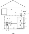
- FIG. 1 schematically depicts an air purification monitoring system 10 according to an embodiment.
- the air purification monitoring system 10 is adapted to control the operation of an air purification apparatus 50 fitted into the enclosed space 1 such as a room of a house, office building or the like.
- the air purification apparatus 50 is at least operable in a first mode in which outdoor air is ventilated into the enclosed space 1.
- Such forced ventilation is performed in this mode at a rate that exceeds the rate of natural or spontaneous ventilation between the enclosed space 1 and the outdoors, e.g. through imperfections in the hermetic seal of the enclosed space 1, which may include opened windows or doors. This will be explained in further detail below.
- the air purification apparatus 50 may also be operable in a second mode in which the indoor air within the enclosed space 1 is circulated through the air purification apparatus 50.
- Such airflows are typically passed through one or more pollutant removal structures fitted within the air purification apparatus 50 in order to purify this air before it is expelled into the enclosed space 1.
- Such an air purification apparatus 50 may be fitted within the enclosed space 1 in any suitable manner, such as through an external wall, roof or window of a building or dwelling enclosing the space 1 such that the air purification apparatus 50 has access to the outdoor space from which the outdoor air is sourced.
- Such an air purification apparatus 50 may contain any suitable type of pollutant removal structures, e.g. filters such as HEPA filters, carbon filters, and so on in order to remove pollutants such as particulate matter, pollen, odours, bacteria, volatile organic compounds (VOCs) such as formaldehyde and toluene, and so on.
- pollutants such as particulate matter, pollen, odour
- the air purification monitoring system 10 typically comprises a computing device 30 including a processor 31.
- the computing device 30 may be any suitable computing device, such as a personal computer, e.g. a desktop computer or a laptop computer, a tablet computer, a personal digital assistant, a mobile communication device such as a smartphone and so on.
- the computing device 30 may form an assembly with the air purifier 50. In such an assembly, the computing device 30 may be a discrete entity or may form part of the air purifier 50, i.e. the air purifier 50 may comprise the processor 31.
- the processor 31 may be any suitable processor, e.g. a generic processor or an application-specific processor.
- the computing device 30 may further comprise a data storage device 33 communicatively coupled to the processor 31.
- the computing device 30 is arranged to communicate with one or more sensors 21, 22, 23.
- sensors may include a pressure sensor 23, a temperature sensor 22 and/or one or more unfavourable matter sensors 21, e.g. analyte sensors, for sensing levels of an unfavourable matter or analyte of interest in the atmosphere within the enclosed space 1 in which the air purification apparatus 50 is placed.
- the first unfavourable matter sensor 21 is arranged to sense a concentration or level of an unfavourable matter for which the air purification apparatus 50 comprises a pollutant removal structure such as an air filter or the like arranged to remove this unfavourable matter.
- the sensor 21 may be a particulate matter sensor such as a PM 2.5 sensor for detecting particulate matter of a certain diameter in the atmosphere, e.g.
- the first unfavourable matter sensor 21 is a carbon dioxide sensor (CO 2 ) to monitor CO 2 levels within the enclosed space 1.
- the air purification apparatus 50 may not comprise a pollutant removal structure capable of removing CO 2 .
- the processor 31 is also communicatively coupled to an outdoor temperature sensor 24 arranged to sense the outdoor temperature.
- an outdoor temperature sensor 24 may be located in any suitable outdoor location, such as for example on an external surface of a dwelling containing the enclosed space 1.
- the processor 31 may be arranged to obtain outdoor temperature information from an external source over a network connection such as the Internet, which external source may be a meteorological service or the like providing real-time temperature information about a geographical location in which this dwelling is located.
- the provision of indoor and outdoor temperature information to the processor 31 is not essential to the present invention such that in alternative embodiments the indoor temperature sensor 23 and/or the outdoor temperature sensor 24 (or the temperature-providing service) may be omitted.
- the external sensor 24 may be a wind speed meter to measure the outdoor wind speeds as will be explained in further detail below.
- the sensors 21, 22, 23 may be integrated in any suitable device, such as the air purification apparatus 50, the computing device 30 or a stand-alone sensor device 20, e.g. a sensor box or the like.
- Stand-alone sensor devices e.g. sensor boxes, are increasingly available for home-use and may include sensors for measuring air pollutants such as volatile organic compounds (VOCs) including formaldehyde and toluene, particulates including PM2.5 as well as environmental parameters such as relative humidity and temperature.
- the processor 31 may be adapted to monitor the concentration of a particular pollutant, the temperature within the enclosed space 1 and/or the pressure within the enclosed space 1 based on the sensor data provided by the sensors 21, 22, 23 of the sensor device 20.
- the processor 31 may be integrated into such a stand-alone sensor device 20, i.e. the stand-alone sensor device 20 may comprise the computing device 30.
- the sensors 21, 22, 23 are communicatively coupled to the computing device 30 over a communication link 25 such that the processor 31 can receive sensor readings from such sensors.
- a communication link may be a wired communication link, e.g. in case the sensors 21, 22, 23 are integral to the computing device 30, or may be a wireless communication link, e.g. in case the sensors 21, 22, 23 are located in a different device to the computing device 30, e.g. in a stand-alone sensor device 20.
- the respective devices communicatively coupled over such a wireless communication link may include a wireless transceiver (not shown).
- the devices may communicate with each other through their respective wireless transceivers using any suitable wireless communication protocol, e.g.
- the respective devices may communicate directly with each other or may communicate with each other through an intermediary such as a wireless bridge, a router, a hub, and so on. Any suitable embodiment of wired or wireless communication between such respective devices may be contemplated.
- the processor 31 may be further communicatively coupled to a data storage device 33, here shown to form part of the computing device 30.
- a data storage device may be any suitable device for storing digital data, e.g. a random access memory, a cache memory, a Flash memory, a solid state storage device, a magnetic storage device such as hard disk, an optical storage device and so on.
- the data storage device 33 may be separate from the computing device 30, e.g. a network storage device or a cloud storage device accessible to the processor 31 over a network such as a LAN or the Internet.
- the processor 31 may store sensor data received from one or more of the connected sensors 21, 22, 23 in the data storage device in order to collect and store historical data, for example regarding the levels of the unfavourable matter interest in the atmosphere within the enclosed space 1 comprising the air purification apparatus 50 from which the processor 31 may derive certain parameters relating to the enclosed space 1 as will be explained in further detail below.
- the computing device 30 further comprises a sensory output device 35 under control of the processor 31.
- a sensory output device may be any device that capable of producing an output that can be detected by one of the human senses.
- the sensory output device 35 may be adapted to produce a visible or audible output.
- the sensory output device 35 may comprise a display and/or one or more LEDs adapted to provide such an output.
- the processor 31 may be adapted to receive sensor data from a plurality of sensors 21 each associated with different unfavourable matter of interest, with the processor 31 adapted to (simultaneously) monitor the respective concentration levels of different unfavourable matter of interest from the sensor data received from the multiple sensors in the sensor device 20.
- the sensory output device 35 forms part of the computing device 30, e.g. may be an integral part of the computing device 30 or may be attached to the computing device 30, e.g. a monitor or loudspeaker attached to the computing device 30.
- the sensory output device 35 may form part of a mobile communication device 40, with the computing device 30 adapted to communicate with the mobile communication device over a wireless communication link 37, e.g. using any of the aforementioned wireless communication protocols.
- the computing device 30 adapted to communicate with the mobile communication device over a wireless communication link 37, e.g. using any of the aforementioned wireless communication protocols.
- any suitable mobile communication device 40 e.g. a smart phone, tablet computer, personal digital assistant, and so on, may be used for this purpose.
- the mobile communication device 40 may be configured with a software application program, e.g. an app, to interact with the computing device 30 as described above.
- the senor(s) 21, 22, 23 as well as the processor 31 and the sensory output device 35 are integrated in the air purification apparatus 50, thereby forming an integrated air purification apparatus 50 according to an embodiment of the present invention.
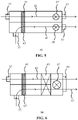
- FIG. 3 depicts an air purification apparatus 50 adapted to generate a ventilation airflow 82 that introduces air from the outdoor space into the enclosed space 1 through a pollutant removal structure 63 in a conduit in between an outdoor inlet 57 and an indoor outlet 53 of the air purification apparatus 50, thereby lowering the concentration of an outdoor unfavourable matter to be introduced into the enclosed space 1.
- the conduit may further house a heat exchanger 70 that adjusts, e.g. heats or cools, the outdoor air prior to its introduction into the enclosed space 1 for the purpose of climate control, as is well-known per se.
- the ventilation airflow 82 may be generated using an air displacement apparatus or device 67, such as a fan, ventilator, ionic wind generator, air pump, or the like.
- a valve arrangement 65 may be present to further regulate the air flow rate of the ventilation airflow 82.
- FIG. 4 depicts an air purification apparatus 50 adapted to generate a first airflow 81, from here on referred to a recirculation airflow 81, a second airflow, i.e. a ventilation airflow 82, and a third airflow 83, from here on referred to as an exhaust airflow 83.
- the recirculation airflow 81 recirculates air from within the enclosed space 1 through a pollutant removal structure 61 in a conduit in between an indoor inlet 55 and a first indoor outlet 53 of the air purification apparatus 50 into the enclosed space 1, thereby lowering the concentration of an indoor unfavourable matter and purifying the indoor air.
- the recirculation airflow 81 may be generated using a first air displacement apparatus or device 67, such as a fan, ventilator, ionic wind generator, air pump, or the like.
- the ventilation airflow 82 introduces air from the outdoor space into the enclosed space 1 through a further pollutant removal structure 63 in a further conduit in between an outdoor inlet 57 and a second indoor outlet 51 of the air purification apparatus 50, thereby lowering the concentration of an outdoor unfavourable matter to be introduced into the enclosed space 1.
- the further conduit may further house a heat exchanger 70 that adjusts, e.g. heats or cools, the outdoor air prior to its introduction into the enclosed space 1 for the purpose of climate control, as is well-known per se.
- the ventilation airflow 81 may be generated using a second air displacement apparatus or device 69, such as a fan, ventilator, ionic wind generator, air pump, or the like.
- the ventilation airflow 82 may be used to generate a positive pressure relative to the outdoor space within the enclosed space 1, thereby forcing air from the enclosed space 1, i.e. ventilating the enclosed space 1, e.g. in order to lower the concentration of an unfavourable matter generated within the enclosed space 1, such as for example VOCs in case of a freshly decorated enclosed space 1 or CO 2 by people being present within the enclosed space 1 and/or to prevent unfiltered outdoor air including high concentrations of unfavorable matter from entering the enclosed space 1 through natural or spontaneous ventilation.
- an unfavourable matter generated within the enclosed space 1 such as for example VOCs in case of a freshly decorated enclosed space 1 or CO 2 by people being present within the enclosed space 1 and/or to prevent unfiltered outdoor air including high concentrations of unfavorable matter from entering the enclosed space 1 through natural or spontaneous ventilation.
- the exhaust airflow 83 may be used to assist forced ventilation of the enclosed space 1 by forcibly expelling indoor air under control of the second air displacement apparatus or device 69 by way of non-limiting example only.
- a third second air displacement apparatus or device (not shown) may be used for this purpose instead.
- the exhaust airflow 83 may be passed through yet a further conduit extending between an indoor inlet such as the second inlet 51 and an outdoor outlet 59.
- the valve arrangement 65 may be present to switch the operation of the second air displacement apparatus or device 69 between generation of the ventilation airflow 82 and the exhaust airflow 83 as will be readily understood by the skilled person.
- the pollutant removal structures 61, 63 within the air purification apparatus 50 may be configured to remove any suitable unfavourable matter from the indoor or outdoor air such as for example O 3 , PM 10, PM 2.5, CO, NO 2 SO 2 , volatile organic compounds such as formaldehyde or toluene, and so on. It should furthermore be understood that in accordance with embodiments of the present invention, the air purification apparatus 50 is arranged to generate at least the ventilation airflow 82, and preferably also the recirculation airflow 81, which may be achieved with any suitable configuration of the air purification apparatus 50.
- FIG. 5 schematically depicts another example embodiment of the air purification apparatus 50, in which the air purification apparatus 50 is configured to generate the recirculation airflow 81 and the ventilation airflow 82 only using independent air displacement apparatuses 67, 69 as previously explained
- FIG. 6 another example embodiment of the air purification apparatus 50 is schematically depicted in which the recirculation airflow 81 and the ventilation airflow 82 are generated using a single air displacement apparatus 67 communicatively coupled to a valve arrangement 65 that allows the air purification apparatus 50 to switch between the recirculation airflow 81 and the ventilation airflow 82 or mixtures thereof.
- FIG. 6 schematically depicts another example embodiment of the air purification apparatus 50, in which the recirculation airflow 81 and the ventilation airflow 82 are generated using a single air displacement apparatus 67 communicatively coupled to a valve arrangement 65 that allows the air purification apparatus 50 to switch between the recirculation airflow 81 and the ventilation airflow 82 or mixtures thereof.
- FIG. 6 further schematically depicts that the recirculation airflow 81 and the ventilation airflow 82 share the same indoor outlet 53 of the air purification apparatus 50, and it should be understood that any of the embodiments of the air purification apparatus 50 these airflows may share such an outlet. It should furthermore be understood that many more configuration variations of the air purification apparatus 50 are of course possible without departing from the teachings of the present invention such that the given example configurations of the air purification apparatus 50 should in no way be construed as limiting the scope of the present invention.
- the air purification apparatus 50 may comprise at least part of the air purification monitoring system 10 and/or the sensor device 20.
- the air purification apparatus 50 may include the air purification monitoring system 10 according to any of the described embodiments communicatively coupled to a separate sensor device 20 according to any of the described embodiments, the air purification apparatus 50 may include both the air purification monitoring system 10 according to any of the described embodiments and the sensor device 20 according to any of the described embodiments.
- the air purification apparatus 50 may include a wired or wireless communication module (not shown) adapted to communicate with the air purification monitoring system 10 according to any of the described embodiments, which itself may be communicatively coupled to a separate sensor device 20 according to any of the described embodiments.
- the air purification apparatus 50 further comprises a controller arrangement (not shown) of the one or more air displacement apparatuses 67, 69 that controls the one or more air displacement apparatuses 67, 69 in accordance with a control signal generated by the processor 31 as will be explained in further detail below.
- a control signal may comprise one or more control instructions for the air purification apparatus 50.
- control instructions configure the air purification apparatus 50 to operate in a particular mode and as such may instruct the air purification apparatus 50 to operate any of the air displacement apparatuses 67, 69, the valve arrangement 65 if present and so on in accordance with the configuration information conveyed by the control signal.
- the processor 31 is adapted to implement the method 100, a flow chart of which is depicted in FIG. 7 .
- the method 100 starts in operation 101, in which the processor 31 is activated, after which the method proceeds to operation 103 in which the processor receives an indication of a spontaneous ventilation rate between the enclosed space and the outdoor space from which the processor 31 determines the spontaneous ventilation rate in operation 105. This preferably is based on both the received indication and an estimation of the volume of the enclosed space 1, as will now be explained in further detail.
- this volume may be specified by a user using any user interface communicatively coupled to the processor 31. This therefore relies on the user providing an accurate estimate of the volume of the enclosed space 1 to ensure that the air purification apparatus 50 can be operated in an efficient manner.
- the volume of the enclosed space 1 may be estimated based on sensor information provided by the sensor device 20.
- a typical CADR curve may be recorded by the analyte sensor 21, e.g. may be expressed using a linear scale on the y-axis of a plot depicting the CADR curve.
- the initial CADR may be used to calculate the room volume Vo, i.e. the volume V of the enclosed space 1 housing the air purification apparatus 50.
- This room volume for instance may be obtained when the air purification apparatus 50 is operated for the first time in a hermetically enclosed space 1.
- Other suitable ways of obtaining the room volume may be applied instead.
- the indication of the spontaneous ventilation rate as received by the processor 31 comprises information concerning the outdoor wind speed, which may be received by the processor 31 from a meteorological service as previously mentioned providing wind speed information for the geographical location of the enclosed space 1 or from a wind speed meter (e.g. an external sensor 24) in this geographical location, e.g. a wind speed meter attached to the dwelling comprising the enclosed space 1.
- a meteorological service as previously mentioned providing wind speed information for the geographical location of the enclosed space 1 or from a wind speed meter (e.g. an external sensor 24) in this geographical location, e.g. a wind speed meter attached to the dwelling comprising the enclosed space 1.
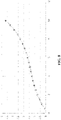
- FIG. 8 depicts a graph showing the rate in (h -1 ) at which the volume of an enclosed space 1 is displaced as a function of the outdoor wind speed (in m/s).
- This graph clearly depicts that with increasing outdoor wind speeds the rate at which spontaneous ventilation between the enclosed space 1 and the outdoor space occurs increases as well, such that the spontaneous ventilation rate of the enclosed space 1 can be estimated from the indicated outdoor wind speed.
- such an indication comprises a series of sensor readings of a concentration of an analyte of interest within the enclosed space 1 over a defined period of time, with the processor 31 being arranged to calculate the spontaneous ventilation rate from said series of sensor readings.
- the processor 31 may be adapted to estimate the natural rate of ventilation Q based on changes in the CO 2 concentration or any other suitable gaseous compound, e.g. volatile organic compounds (VOCs), within the enclosed space 1 housing the air purification apparatus 50 when one or more persons are present in the air-filled space and the air purification apparatus 50 is switched off.
- VOCs volatile organic compounds
- the level of CO 2 within the air-filled space should increase in accordance with the number of people within the air-filled space and its volume. Deviations from such expected increase, i.e. a smaller increase in CO 2 levels over time than expected, can be attributed to ventilation between the air-filled space and the outside world.
- C outdoor is the ambient CO 2 concentration (in g/m 3 ) in the outside world in ventilation with the air-filled space
- S is the CO 2 source strength (in g/m 3 ) within the air-filled space.
- the CO 2 source strength of an individual (Si) typically is within a given range (e.g. within a range of 0.16-0.33 1/min for an adult).
- the number N of individuals within the air-filled space may be determined in any suitable manner, e.g. the number N may be specified by a user through a user interface of the air purification monitoring system 10 or alternatively the air purification monitoring system 10 may comprise one or more sensors (not shown), e.g. motion detection sensors or the like, for detecting the presence of individuals within the air-filled space.
- the enclosed space 1 exhibits a low rate of ventilation whereas in FIG. 10 the enclosed space 1 exhibits a high rate of ventilation, as evidenced by the high degree of fluctuations in the natural ventilation rate Q due to changes in ambient conditions such as wind conditions. This leads to noticeable differences in the build-up of CO 2 within the enclosed space 1, which may be used to estimate the rate of spontaneous (natural) ventilation between the enclosed space 1 and the outdoor space.
- the processor 31 may determine the natural rate of ventilation Q between the enclosed space 1 housing the air purification apparatus 50 and the outside world based on a series of sensor signals received from a CO 2 sensor 21, as the trend in the CO 2 concentration in the air-filled space can be used to determine the spontaneous rate of ventilation Q, i.e. the rate of ventilation when the air purification apparatus 50 is switched off, as has been explained in more detail above with the aid of equation (5). It should be understood that equation (5) is provided by way of non-limiting example only and that other equations from which the rate of ventilation Q can be derived based on such trends in CO 2 may also be used.
- the processor 31 may obtain the ambient CO 2 concentration for determining the rate of ventilation Q in any suitable manner, e.g.
- the processor 31 may obtain the ambient CO 2 concentration at any suitable point in time.
- the natural ventilation rate Q may be determined by monitoring other gaseous compounds generated by persons within the air-filled space, e.g. volatile organic compounds.
- the source strength S is not necessarily limited to the generation of CO 2 by people within the enclosed space 1. It is for instance equally feasible that the source strength S represents a rate of release of another unfavourable matter, such as a volatile organic compound being released within a freshly decorated enclosed space 1.
- the spontaneous rate of ventilation of the enclosed room 1 may be estimated in any other suitable manner, such as a user-specified estimate provided through a user interface in communication with the processor 31.
- the processor 31 may receive a series of sensor readings from the analyte sensor 21 such as a CO 2 sensor or VOC sensor, e.g. in order to monitor changes in the CO 2 levels within the enclosed space 1, as such changes may be indicative of changes in the volume of the enclosed space, e.g. by a door or the like between the enclosed space 1 and an adjacent space being opened or closed or a change in ventilation conditions between the air-filled space and the outside world.
- a change in the volume or ventilation conditions of the air-filled space can be detected by a sudden change in the unfavourable matter levels and/or CO 2 levels (or levels of other pollutants monitored to determine the occupancy rate of the enclosed space 1 as previously explained).
- the processor 31 detects a sudden change in unfavourable matter concentration and CO 2 concentration, this may be indicative of a change in the volume of the enclosed space 1 or a change in the ventilation conditions of the enclosed space 1.
- the processor 31 may distinguish between a change in volume and a change in ventilation conditions in the following manner.
- a change in volume of the enclosed space 1 after the initial sudden change in monitored pollutant and CO 2 levels, these levels will gradually decrease until an equilibrium is reached between the two connected spaces.
- the CO 2 levels typically remain higher than the typical ambient CO 2 levels of about 400 ppm.
- the CO 2 level in the air-filled space will rapidly equilibrate with ambient CO 2 levels, i.e. reach levels of about 400 ppm.
- the indication of the spontaneous ventilation rate of the enclosed space 1 comprises temperature information including the outdoor air temperature and the indoor air temperature, with the processor 31 being arranged to calculate the spontaneous ventilation rate from a difference between the outdoor air temperature and the indoor air temperature.
- the indoor temperature i.e. the temperature within the enclosed space 1 may be determined with the temperature sensor 22 and the outdoor temperature may be determined with the outdoor temperature sensor 24 or alternatively may be provided by an external source such as a meteorological service as previously explained.
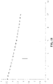
- FIG. 11 schematically depicts a graph showing a relationship between the rate (in h -1 ) at which the volume of an enclosed space 1 is fully replenished through spontaneous ventilation and the temperature difference (in °C) between the indoor and outdoor temperature. From this graph, it can be seen that an indication of the spontaneous ventilation rate of the enclosed space 1 can be obtained from the temperature difference between these indoor and outdoor temperatures.
- the method 100 Upon determining the spontaneous ventilation rate, the method 100 proceeds to operation 107 in which the processor 31 generates a control signal for the air flow displacement arrangement as a function of the determined spontaneous ventilation rate.
- the control signal causes the air flow displacement arrangement 65, 67 and/or 69 of the air purification apparatus 50 to control a rate of the forced ventilation airflow 82 such that the forced ventilation airflow rate exceeds the spontaneous ventilation rate.
- spontaneous ventilation of outdoor air into the enclosed space 1 is effectively suppressed, such that outdoor air predominantly enters the enclosed space 1 through the forced ventilation induced by the air purification apparatus 50, which ensures that unfavourable matter in the outdoor air is largely removed therefrom by the filter arrangement 62 within the air purification apparatus 50 through which the outdoor air is passed before being released into the enclosed space 1.
- the method 100 terminates in operation 109.
- the method 100 may only be invoked if the outdoor concentration of a particular type of unfavourable matter has exceeded a defined threshold above which the concentration of this unfavourable matter may be considered potentially harmful.
- the outdoor concentration of the unfavourable matter of interest may be obtained in any suitable manner, e.g. using outdoor analyte sensor or an external service providing real-time information about such concentrations within the geographical location of the enclosed space 1.
- the processor 31 may be responsive to a pressure sensor 23 that monitors the pressure within the enclosed space 1. For example, based on the determined spontaneous ventilation rate for the enclosed space 1, the processor 31 may calculate a target pressure to be generated within the enclosed space 1 with the air purification apparatus 50 in the forced ventilation mode as previously explained.
- the pressure sensor 23 may be used as a feedback mechanism to determine if the air purification apparatus 50 is operated correctly, more specifically, if the rate of the forced ventilation results in the desired pressure within the enclosed space 1.
- the processor 31 may generate a further control signal for the air purification apparatus 50 that adjusts the forced ventilation rate generated with the air purification apparatus 50 in order to reduce the deviation of the actual pressure within the enclosed space 1 from the desired pressure. In this manner, it is for instance can be avoided that an unnecessarily high overpressure is generated within the enclosed space 1. In other words, this pressure feedback ensures that the air purification apparatus 50 is operated as efficiently as possible.
- the above described embodiments of the method 100 executed by the processor 31 may be realized by computer readable program instructions embodied on a computer readable storage medium having, when executed on the processor 31, cause the processor arrangement 31 to implement the method 100.
- Any suitable computer readable storage medium may be used for this purpose, such as for example an optically readable medium such as a CD, DVD or Blu-Ray disc, a magnetically readable medium such as a hard disk, an electronic data storage device such as a memory stick or the like, and so on.
- the computer readable storage medium may be a medium that is accessible over a network such as the Internet, such that the computer readable program instructions may be accessed over the network.
- the computer readable storage medium may be a network-attached storage device, a storage area network, cloud storage or the like.
- the computer readable storage medium may be an Internet-accessible service from which the computer readable program instructions may be obtained.
- the processor 31 is adapted to retrieve the computer readable program instructions from such a computer readable storage medium and to create a new computer readable storage medium by storing the retrieved computer readable program instructions in the data storage device 33.
Description
- The present invention relates to an air purification monitoring system for monitoring an air purification apparatus adapted to purify air in an enclosed space.
- The present invention further relates to an air purification apparatus adapted to be controlled by such an air purification monitoring system.
- The present invention further relates to a method of controlling such an air purification apparatus.
- The present invention further relates to a computer program product for implementing such a method on an air purification monitoring system.
- Air purifiers are commonplace in today's society to clean air in confined spaces, e.g. rooms, for example to reduce the exposure of people in such confined spaces to harmful or unpleasant pollutants, e.g. allergens, particles, odours, and so on. To this end, the air purifiers typically comprise one or more pollutant removal structures, such as one or more filters, catalytic converters, electrostatic precipitators, and so on. The one or more filters may include air filters such as carbon filters, HEPA filters, odour filters, anti-bacterial filters or the like. Catalytic converters may be used to break down gaseous pollutants into smaller molecules, e.g. H2O and CO2. Electrostatic precipitators may be employed for the removal of charged particles via collector plates. Other pollutant removal technologies employed in such purifiers are also known.
- A particular class of air purifiers includes fresh air purification units (FAPUs), in which fresh air, i.e. outdoor air, is introduced into the confined space after being passed through one or more of the pollutant removal structures in order to at least partially remove potentially harmful constituents from the fresh air, e.g. pollutants such as particulate matter, NOx, ozone and so on, which can cause health problems such as respiratory conditions, e.g. asthma, if sufferers from such conditions are exposed to such matter. However, the filtration capacity of such FAPUs is limited, which means that when the outdoor air is heavily polluted residual pollution will enter the confined space, which is highly undesirable. In addition, such heavy pollution can quickly saturate the pollutant removal structures in such a FAPU, such that these pollutant removal structures have to be regularly replaced.
- This problem may be addressed by using a stand-alone air purifier within the confined space, which typically has high efficiency in particulate matter removal such that particulate matter entering the confined space from outside through natural ventilation can be effectively removed. In order to let such stand-alone air purifier work as efficiently as possible, it is recommended that such devices are operated in a hermetically sealed space, but this has the drawback that a build-up can occur of potentially harmful matter generated within the confined space. Such matter will also be referred to as unfavourable matter, that is, airborne constituents that, at least at certain concentrations, can be harmful to a person inhaling such matter. For example, indoor CO2 concentrations should be kept below certain thresholds, as elevated CO2 levels can cause drowsiness and headaches to persons exposed to such elevated levels. Other examples of such unfavourable matter include volatile organic compounds (VOCs) such as formaldehyde and toluene, which may be present in elevated levels after decoration of the confined space and which can compromise the health of persons exposed to such compounds.
- Another way of preventing polluted outdoor air, e.g. automobile exhaust gases, from entering such an enclosed space is provided in
KR 2008/104744 -
US 2013/239803 A1 discloses reducing airborne contamination within a home using an air-pressure control system installed within a window of the home. -
WO 2013/001155 A1 discloses contolling the pressure and air conditioning in a multi-story building. - The present invention seeks to provide an air purification monitoring system for monitoring an air purification apparatus that ensures that the air purification apparatus is operated at improved efficiency when purifying the air within an enclosed space.
- The present invention further seeks to provide an air purification apparatus that can be controlled with such an air purification monitoring system.
- The present invention further seeks to provide a computer-implemented method of controlling such an air purification apparatus.
- The present invention further seeks to provide a computer program product that can be used to configure an air purification monitoring system to implement this computer-implemented method.
- According to an aspect, there is provided an air purification monitoring system for monitoring an air purification apparatus adapted to purify air in an enclosed space, the air purification apparatus comprising a first inlet for receiving outdoor air from an outdoor space and at least one outlet coupled to the first inlet; a filter arrangement positioned in between the first inlet and the at least one outlet; and an air flow displacement arrangement arranged to generate a forced ventilation airflow from the first inlet to the at least one outlet; the air purification monitoring system comprising a processor arranged to receive an indication of a spontaneous ventilation rate between the enclosed space and the outdoor space; determine the spontaneous ventilation rate from said received indication; and generate a control signal for the air flow displacement arrangement as a function of said calculated spontaneous ventilation rate, said control signal causing the air flow displacement arrangement to control a rate of the forced ventilation airflow such that the forced ventilation airflow rate exceeds the spontaneous ventilation rate.
- The present invention is based on the insight that the optimal mode of operation of an air purification apparatus in terms of efficiency is achieved when the air purification apparatus forces an airflow into the enclosed space at a rate that exceeds the spontaneous ventilation rate between the enclosed space and the outdoors by a defined, e.g. a small, amount, such that a positive pressure is created within the enclosed space that prevents outdoor unfavourable matter such as particulate matter or other pollutants from entering the enclosed space whilst the amount of energy required by the air purification apparatus to generate such a positive pressure is minimized. This is achieved by obtaining the estimate of the rate of spontaneous ventilation, based on which the air purification apparatus is operated.
- In an embodiment, the processor is arranged to determine the spontaneous ventilation rate based on said indication and a volume of the enclosed space in order to obtain an accurate estimate of the rate of spontaneous ventilation.
- The indication may comprise a series of sensor readings of a concentration of an analyte of interest within the enclosed space over time, and wherein the processor is arranged to calculate the spontaneous ventilation rate from said series of sensor readings. For example, in a scenario where a generation rate of the analyte of interest is known, the spontaneous ventilation rate may of the enclosed space be obtained from such a series of sensor readings. To this end, the air purification monitoring system may further comprise an analyte sensor arranged to provide said series of sensor readings. Alternatively, the sensor readings may be provided by an analyte sensor external to the air purification monitoring system.
- In another embodiment, the indication comprises outdoor wind speed information. This embodiment is based on the insight that there exists a direct relationship between the rate of spontaneous ventilation of the enclosed space and the outdoor wind speed such that the rate of spontaneous ventilation can be derived from such an indication of the outdoor wind speed.
- In yet another embodiment, the indication comprises the outdoor air temperature and the indoor air temperature, and wherein the processor is arranged to calculate the spontaneous ventilation rate from a difference between the outdoor air temperature and the indoor air temperature. This embodiment is based on the insight that there exists a direct relationship between the rate of spontaneous ventilation of the enclosed space and a temperature gradient between the outdoor temperature and the indoor temperature, i.e. the temperature within the enclosed space, such that the rate of spontaneous ventilation can be derived from the difference between these temperatures. To this end, the air purification monitoring system may further comprise at least one of an indoor temperature sensor for determining the indoor air temperature and an outdoor temperature sensor for determining the outdoor air temperature. Alternatively, such temperature readings may be obtained from an alternative source external to the air purification monitoring system.
- The processor may be further arranged to receive a pressure sensor reading from a pressure sensor indicating a pressure within the enclosed space; and generate the control signal for the air flow displacement arrangement as a function of said spontaneous ventilation rate and the pressure sensor reading. The air purification monitoring system optionally may comprise such a pressure sensor. In this manner, a feedback mechanism may be provided in which the pressure reading is used to ensure that the correct amount of positive pressure is generated within the enclosed space, thereby further improving the efficiency of the air purification apparatus.
- According to another aspect, there is provided an air purification apparatus adapted to purify air in an enclosed space, comprising a first inlet for receiving outdoor air from an outdoor space and at least one outlet coupled to the first inlet; a filter arrangement positioned in between the first inlet and the at least one outlet; and an air flow displacement arrangement arranged to generate a forced ventilation airflow from the first inlet to the at least one outlet, wherein the air flow displacement arrangement is responsive to the control signal generated with the air purification monitoring system according to any of the herein described embodiments. Such an air purification apparatus benefits from being operable in an efficient manner in order to create a positive pressure within the enclosed space to prevent unfavourable matter from outdoor entering the enclosed space as previously explained.
- In at least some embodiments, the air purification apparatus further comprises the air purification monitoring system according to any of the herein described embodiments, thereby providing a self-contained air purification apparatus that includes the inventive air purification monitoring system.
- The air purification apparatus may further comprise a second inlet for receiving indoor air from the enclosed space coupled to the at least one outlet, wherein the filter arrangement is positioned in between the first and second inlets and the at least one outlet; and the air flow displacement arrangement is further arranged to generate a recirculation airflow from the second inlet to the at least one outlet. This has the advantage that the indoor air may also be purified by the air purification apparatus, e.g. to reduce concentration of unfavourable matter such as volatile organic compounds or the like. Additional embodiments may include an air purification apparatus further comprising an exhaust mode in which the indoor air is vented to outdoors, which for example may be advantageous when the indoor air comprises a high concentration of unfavourable matter that cannot be removed by the filter arrangement, e.g. CO2 or the like, in which case such contaminated air can be removed from the enclosed space.
- According to yet another aspect, there is provided a computer implemented method for generating a control signal for controlling the air purification apparatus of any of the herein described embodiments, the method comprising receiving an indication of a spontaneous ventilation rate between the enclosed space and the outdoor space; determining the spontaneous ventilation rate from said received indication; and generating a control signal for the air flow displacement arrangement as a function of said calculated spontaneous ventilation rate, said control signal causing the air flow displacement arrangement to control a rate of the forced ventilation airflow such that the forced ventilation airflow rate exceeds the spontaneous ventilation rate. The generation of such a control signal facilitates the control of the air purification apparatus such that the air purification apparatus operates in a highly efficient manner whilst establishing a positive pressure within the enclosed space as previously explained.
- Preferably, determining the spontaneous ventilation rate from said received indication comprises determining the spontaneous ventilation rate based on said indication and a volume of the enclosed space in order to obtain a particularly accurate estimate of the spontaneous ventilation rate.
- According to still another aspect, there is provided a computer program product comprising a computer readable storage medium having computer readable program instructions embodied therewith for, when executed on the processor of the air purification monitoring system of any of the herein described embodiments, causes the processor to implement the method of any of the herein described embodiments. Such a computer program product may be used to reconfigure an existing air purification monitoring system, which may be more cost-effective than replacing such a system in order to implement the functionality according to embodiments of the present invention.
- Embodiments of the invention are described in more detail and by way of non-limiting examples with reference to the accompanying drawings, wherein:
-
FIG. 1 schematically depicts an air purification arrangement including an air purification monitoring system according to an embodiment; -
FIG. 2 schematically depicts an air purification arrangement including an air purification monitoring system according to another embodiment; -
FIG. 3 schematically depicts an air purification apparatus according to an example embodiment; -
FIG. 4 schematically depicts an air purification apparatus according to another example embodiment; -
FIG. 5 schematically depicts an air purification apparatus according to yet another example embodiment; -
FIG. 6 schematically depicts an air purification apparatus according to yet another example embodiment; -
FIG. 7 is a flowchart of a method of controlling an air purification apparatus located in an air-filled space according to an embodiment; -
FIG. 8 shows a graph depicting the relationship between outdoor wind speed (x-axis, m/s) and spontaneous ventilation rate (y-axis, h-1); -
FIG. 9 shows a set of graphs associated with a first ventilation condition of a room in which an air purification apparatus according to an embodiment of the present invention is placed; -
FIG. 10 shows a set of graphs associated with a second ventilation condition of a room in which an air purification apparatus according to an embodiment of the present invention is placed; and -
FIG. 11 shows a graph depicting the relationship between outdoor and indoor temperature gradient (x-axis, °C) and spontaneous ventilation rate (y-axis, h-1). - It should be understood that the Figures are merely schematic and are not drawn to scale. It should also be understood that the same reference numerals are used throughout the Figures to indicate the same or similar parts.
-
FIG. 1 schematically depicts an airpurification monitoring system 10 according to an embodiment. The airpurification monitoring system 10 is adapted to control the operation of anair purification apparatus 50 fitted into theenclosed space 1 such as a room of a house, office building or the like. As will be explained in further detail below, theair purification apparatus 50 is at least operable in a first mode in which outdoor air is ventilated into theenclosed space 1. Such forced ventilation is performed in this mode at a rate that exceeds the rate of natural or spontaneous ventilation between theenclosed space 1 and the outdoors, e.g. through imperfections in the hermetic seal of theenclosed space 1, which may include opened windows or doors. This will be explained in further detail below. In some embodiments, theair purification apparatus 50 may also be operable in a second mode in which the indoor air within theenclosed space 1 is circulated through theair purification apparatus 50. Such airflows are typically passed through one or more pollutant removal structures fitted within theair purification apparatus 50 in order to purify this air before it is expelled into theenclosed space 1. Such anair purification apparatus 50 may be fitted within theenclosed space 1 in any suitable manner, such as through an external wall, roof or window of a building or dwelling enclosing thespace 1 such that theair purification apparatus 50 has access to the outdoor space from which the outdoor air is sourced. Such anair purification apparatus 50 may contain any suitable type of pollutant removal structures, e.g. filters such as HEPA filters, carbon filters, and so on in order to remove pollutants such as particulate matter, pollen, odours, bacteria, volatile organic compounds (VOCs) such as formaldehyde and toluene, and so on. - The air
purification monitoring system 10 typically comprises acomputing device 30 including aprocessor 31. Thecomputing device 30 may be any suitable computing device, such as a personal computer, e.g. a desktop computer or a laptop computer, a tablet computer, a personal digital assistant, a mobile communication device such as a smartphone and so on. Thecomputing device 30 may form an assembly with theair purifier 50. In such an assembly, thecomputing device 30 may be a discrete entity or may form part of theair purifier 50, i.e. theair purifier 50 may comprise theprocessor 31. Theprocessor 31 may be any suitable processor, e.g. a generic processor or an application-specific processor. Thecomputing device 30 may further comprise adata storage device 33 communicatively coupled to theprocessor 31. - The
computing device 30 is arranged to communicate with one ormore sensors pressure sensor 23, atemperature sensor 22 and/or one or moreunfavourable matter sensors 21, e.g. analyte sensors, for sensing levels of an unfavourable matter or analyte of interest in the atmosphere within theenclosed space 1 in which theair purification apparatus 50 is placed. Typically, the firstunfavourable matter sensor 21 is arranged to sense a concentration or level of an unfavourable matter for which theair purification apparatus 50 comprises a pollutant removal structure such as an air filter or the like arranged to remove this unfavourable matter. For example, thesensor 21 may be a particulate matter sensor such as a PM 2.5 sensor for detecting particulate matter of a certain diameter in the atmosphere, e.g. PM2.5 or PM10, dust particles, allergens, or the like, a formaldehyde sensor, a toluene sensor, and so on. Alternatively, the firstunfavourable matter sensor 21 is a carbon dioxide sensor (CO2) to monitor CO2 levels within theenclosed space 1. In this scenario, as will be understood by the skilled person, theair purification apparatus 50 may not comprise a pollutant removal structure capable of removing CO2. - In a particular embodiment, the
processor 31 is also communicatively coupled to anoutdoor temperature sensor 24 arranged to sense the outdoor temperature. Such anoutdoor temperature sensor 24 may be located in any suitable outdoor location, such as for example on an external surface of a dwelling containing theenclosed space 1. Alternatively, theprocessor 31 may be arranged to obtain outdoor temperature information from an external source over a network connection such as the Internet, which external source may be a meteorological service or the like providing real-time temperature information about a geographical location in which this dwelling is located. However, as will be explained in further detail below, the provision of indoor and outdoor temperature information to theprocessor 31 is not essential to the present invention such that in alternative embodiments theindoor temperature sensor 23 and/or the outdoor temperature sensor 24 (or the temperature-providing service) may be omitted. In yet another embodiment, theexternal sensor 24 may be a wind speed meter to measure the outdoor wind speeds as will be explained in further detail below. - The
sensors air purification apparatus 50, thecomputing device 30 or a stand-alone sensor device 20, e.g. a sensor box or the like. Stand-alone sensor devices, e.g. sensor boxes, are increasingly available for home-use and may include sensors for measuring air pollutants such as volatile organic compounds (VOCs) including formaldehyde and toluene, particulates including PM2.5 as well as environmental parameters such as relative humidity and temperature. Theprocessor 31 may be adapted to monitor the concentration of a particular pollutant, the temperature within theenclosed space 1 and/or the pressure within theenclosed space 1 based on the sensor data provided by thesensors sensor device 20. In an embodiment, theprocessor 31 may be integrated into such a stand-alone sensor device 20, i.e. the stand-alone sensor device 20 may comprise thecomputing device 30. - The
sensors computing device 30 over acommunication link 25 such that theprocessor 31 can receive sensor readings from such sensors. Such a communication link may be a wired communication link, e.g. in case thesensors computing device 30, or may be a wireless communication link, e.g. in case thesensors computing device 30, e.g. in a stand-alone sensor device 20. To this end, the respective devices communicatively coupled over such a wireless communication link may include a wireless transceiver (not shown). The devices may communicate with each other through their respective wireless transceivers using any suitable wireless communication protocol, e.g. Bluetooth, Wi-Fi, a mobile communication protocol such as 2G, 3G, 4G or 5G, a suitable near-field communication (NFC) protocol or a proprietary protocol. In case of such wireless communication, the respective devices may communicate directly with each other or may communicate with each other through an intermediary such as a wireless bridge, a router, a hub, and so on. Any suitable embodiment of wired or wireless communication between such respective devices may be contemplated. - The
processor 31 may be further communicatively coupled to adata storage device 33, here shown to form part of thecomputing device 30. Such a data storage device may be any suitable device for storing digital data, e.g. a random access memory, a cache memory, a Flash memory, a solid state storage device, a magnetic storage device such as hard disk, an optical storage device and so on. Alternatively, thedata storage device 33 may be separate from thecomputing device 30, e.g. a network storage device or a cloud storage device accessible to theprocessor 31 over a network such as a LAN or the Internet. Theprocessor 31 may store sensor data received from one or more of theconnected sensors enclosed space 1 comprising theair purification apparatus 50 from which theprocessor 31 may derive certain parameters relating to theenclosed space 1 as will be explained in further detail below. - In
FIG. 1 , thecomputing device 30 further comprises asensory output device 35 under control of theprocessor 31. Such a sensory output device may be any device that capable of producing an output that can be detected by one of the human senses. For example, thesensory output device 35 may be adapted to produce a visible or audible output. For example, thesensory output device 35 may comprise a display and/or one or more LEDs adapted to provide such an output. - As will be readily understood by the skilled person, the
processor 31 may be adapted to receive sensor data from a plurality ofsensors 21 each associated with different unfavourable matter of interest, with theprocessor 31 adapted to (simultaneously) monitor the respective concentration levels of different unfavourable matter of interest from the sensor data received from the multiple sensors in thesensor device 20. - In the above embodiment, the
sensory output device 35 forms part of thecomputing device 30, e.g. may be an integral part of thecomputing device 30 or may be attached to thecomputing device 30, e.g. a monitor or loudspeaker attached to thecomputing device 30. In an alternative arrangement schematically depicted inFIG. 2 , thesensory output device 35 may form part of amobile communication device 40, with thecomputing device 30 adapted to communicate with the mobile communication device over awireless communication link 37, e.g. using any of the aforementioned wireless communication protocols. In this embodiment, may be able to control the operation of theair purification apparatus 50 even when not in direct vicinity of thecomputing device 30, e.g. when being in a different room or being outside the building comprising theair purification apparatus 50, which for example is advantageous in order to ensure that theenclosed space 1 is conditioned to a desired condition in anticipation of the arrival of the user of themobile communication device 40 in theenclosed space 1. Any suitablemobile communication device 40, e.g. a smart phone, tablet computer, personal digital assistant, and so on, may be used for this purpose. As will be readily understood by the skilled person, themobile communication device 40 may be configured with a software application program, e.g. an app, to interact with thecomputing device 30 as described above. - In yet another embodiment, the sensor(s) 21, 22, 23 as well as the
processor 31 and thesensory output device 35 are integrated in theair purification apparatus 50, thereby forming an integratedair purification apparatus 50 according to an embodiment of the present invention. - Next, some examples of an
air purification apparatus 50 according to embodiments of the present invention will be described in further detail. A first example is schematically depicted inFIG. 3 , which depicts anair purification apparatus 50 adapted to generate aventilation airflow 82 that introduces air from the outdoor space into theenclosed space 1 through apollutant removal structure 63 in a conduit in between anoutdoor inlet 57 and anindoor outlet 53 of theair purification apparatus 50, thereby lowering the concentration of an outdoor unfavourable matter to be introduced into theenclosed space 1. The conduit may further house aheat exchanger 70 that adjusts, e.g. heats or cools, the outdoor air prior to its introduction into theenclosed space 1 for the purpose of climate control, as is well-known per se. Theventilation airflow 82 may be generated using an air displacement apparatus ordevice 67, such as a fan, ventilator, ionic wind generator, air pump, or the like. Avalve arrangement 65 may be present to further regulate the air flow rate of theventilation airflow 82. - Another example of such an
air purification apparatus 50 is schematically depicted inFIG. 4 , which depicts anair purification apparatus 50 adapted to generate afirst airflow 81, from here on referred to arecirculation airflow 81, a second airflow, i.e. aventilation airflow 82, and athird airflow 83, from here on referred to as anexhaust airflow 83. Therecirculation airflow 81 recirculates air from within theenclosed space 1 through apollutant removal structure 61 in a conduit in between anindoor inlet 55 and a firstindoor outlet 53 of theair purification apparatus 50 into theenclosed space 1, thereby lowering the concentration of an indoor unfavourable matter and purifying the indoor air. Therecirculation airflow 81 may be generated using a first air displacement apparatus ordevice 67, such as a fan, ventilator, ionic wind generator, air pump, or the like. - The
ventilation airflow 82 introduces air from the outdoor space into theenclosed space 1 through a furtherpollutant removal structure 63 in a further conduit in between anoutdoor inlet 57 and a secondindoor outlet 51 of theair purification apparatus 50, thereby lowering the concentration of an outdoor unfavourable matter to be introduced into theenclosed space 1. The further conduit may further house aheat exchanger 70 that adjusts, e.g. heats or cools, the outdoor air prior to its introduction into theenclosed space 1 for the purpose of climate control, as is well-known per se. Theventilation airflow 81 may be generated using a second air displacement apparatus ordevice 69, such as a fan, ventilator, ionic wind generator, air pump, or the like. - As will be explained in more detail below, the
ventilation airflow 82 may be used to generate a positive pressure relative to the outdoor space within theenclosed space 1, thereby forcing air from theenclosed space 1, i.e. ventilating theenclosed space 1, e.g. in order to lower the concentration of an unfavourable matter generated within theenclosed space 1, such as for example VOCs in case of a freshly decoratedenclosed space 1 or CO2 by people being present within theenclosed space 1 and/or to prevent unfiltered outdoor air including high concentrations of unfavorable matter from entering theenclosed space 1 through natural or spontaneous ventilation. - The
exhaust airflow 83 may be used to assist forced ventilation of theenclosed space 1 by forcibly expelling indoor air under control of the second air displacement apparatus ordevice 69 by way of non-limiting example only. A third second air displacement apparatus or device (not shown) may be used for this purpose instead. Theexhaust airflow 83 may be passed through yet a further conduit extending between an indoor inlet such as thesecond inlet 51 and anoutdoor outlet 59. Thevalve arrangement 65 may be present to switch the operation of the second air displacement apparatus ordevice 69 between generation of theventilation airflow 82 and theexhaust airflow 83 as will be readily understood by the skilled person. - As previously mentioned, the
pollutant removal structures air purification apparatus 50 may be configured to remove any suitable unfavourable matter from the indoor or outdoor air such as for example O3,PM 10, PM 2.5, CO, NO2 SO2, volatile organic compounds such as formaldehyde or toluene, and so on. It should furthermore be understood that in accordance with embodiments of the present invention, theair purification apparatus 50 is arranged to generate at least theventilation airflow 82, and preferably also therecirculation airflow 81, which may be achieved with any suitable configuration of theair purification apparatus 50. - For example,
FIG. 5 schematically depicts another example embodiment of theair purification apparatus 50, in which theair purification apparatus 50 is configured to generate therecirculation airflow 81 and theventilation airflow 82 only using independentair displacement apparatuses FIG. 6 another example embodiment of theair purification apparatus 50 is schematically depicted in which therecirculation airflow 81 and theventilation airflow 82 are generated using a singleair displacement apparatus 67 communicatively coupled to avalve arrangement 65 that allows theair purification apparatus 50 to switch between therecirculation airflow 81 and theventilation airflow 82 or mixtures thereof.FIG. 6 further schematically depicts that therecirculation airflow 81 and theventilation airflow 82 share the sameindoor outlet 53 of theair purification apparatus 50, and it should be understood that any of the embodiments of theair purification apparatus 50 these airflows may share such an outlet. It should furthermore be understood that many more configuration variations of theair purification apparatus 50 are of course possible without departing from the teachings of the present invention such that the given example configurations of theair purification apparatus 50 should in no way be construed as limiting the scope of the present invention. - Although not specifically shown in these example embodiments, the
air purification apparatus 50 may comprise at least part of the airpurification monitoring system 10 and/or thesensor device 20. For example, theair purification apparatus 50 may include the airpurification monitoring system 10 according to any of the described embodiments communicatively coupled to aseparate sensor device 20 according to any of the described embodiments, theair purification apparatus 50 may include both the airpurification monitoring system 10 according to any of the described embodiments and thesensor device 20 according to any of the described embodiments. - Alternatively, the
air purification apparatus 50 may include a wired or wireless communication module (not shown) adapted to communicate with the airpurification monitoring system 10 according to any of the described embodiments, which itself may be communicatively coupled to aseparate sensor device 20 according to any of the described embodiments. In this case, theair purification apparatus 50 further comprises a controller arrangement (not shown) of the one or moreair displacement apparatuses air displacement apparatuses processor 31 as will be explained in further detail below. In the context of the present application, such a control signal may comprise one or more control instructions for theair purification apparatus 50. Such control instructions configure theair purification apparatus 50 to operate in a particular mode and as such may instruct theair purification apparatus 50 to operate any of theair displacement apparatuses valve arrangement 65 if present and so on in accordance with the configuration information conveyed by the control signal. - In accordance with embodiments of the present invention, the
processor 31 is adapted to implement themethod 100, a flow chart of which is depicted inFIG. 7 . Themethod 100 starts inoperation 101, in which theprocessor 31 is activated, after which the method proceeds tooperation 103 in which the processor receives an indication of a spontaneous ventilation rate between the enclosed space and the outdoor space from which theprocessor 31 determines the spontaneous ventilation rate inoperation 105. This preferably is based on both the received indication and an estimation of the volume of theenclosed space 1, as will now be explained in further detail. - Regarding the determination of the volume of the
enclosed space 1, in a straightforward embodiment this volume may be specified by a user using any user interface communicatively coupled to theprocessor 31. This therefore relies on the user providing an accurate estimate of the volume of theenclosed space 1 to ensure that theair purification apparatus 50 can be operated in an efficient manner. - In an alternative embodiment, the volume of the
enclosed space 1 may be estimated based on sensor information provided by thesensor device 20. Specifically, the room volume may be derived from a monitored indoor particle (pollutant) concentration, e.g. with theanalyte sensor 21, which obeysequation 1 based on the mass conservation law:
- In the formula:
- C Indoor particle concentration, g/m3;
- Pp Penetration coefficient of particles from the outside world into the air-filled space housing the
air purification apparatus 50, this coefficient typically is around 0.8 in an average domestic dwelling; - Cout Outdoor particle concentration, g/m3, which may be obtained as explained in the present application;
- k0 Particle natural sedimentation rate, h-1, normally around 0.2 h-1;
- kv Air changing rate, h-1;
- V Room volume, m3;
- CADR Clean Air Delivery Rate, m3/h.
- A typical CADR curve may be recorded by the
analyte sensor 21, e.g. may be expressed using a linear scale on the y-axis of a plot depicting the CADR curve. The recorded CADR curve can be expressed by equation (2):
- By combining equations (1) and (2), the following equation (3) is obtained:

- By substituting -km ∗ e -kt = -kC, equation (4) may be obtained as follows:

- The initial CADR may be used to calculate the room volume Vo, i.e. the volume V of the
enclosed space 1 housing theair purification apparatus 50. This room volume for instance may be obtained when theair purification apparatus 50 is operated for the first time in a hermeticallyenclosed space 1. Other suitable ways of obtaining the room volume may be applied instead. - In a first set of embodiments, the indication of the spontaneous ventilation rate as received by the
processor 31 comprises information concerning the outdoor wind speed, which may be received by theprocessor 31 from a meteorological service as previously mentioned providing wind speed information for the geographical location of theenclosed space 1 or from a wind speed meter (e.g. an external sensor 24) in this geographical location, e.g. a wind speed meter attached to the dwelling comprising theenclosed space 1. - It is known per se that a relationship exists between outdoor wind speeds and a spontaneous rate of ventilation between an
enclosed space 1 in communication with the outdoors. This relationship is schematically depicted inFIG. 8 , which depicts a graph showing the rate in (h-1) at which the volume of anenclosed space 1 is displaced as a function of the outdoor wind speed (in m/s). This graph clearly depicts that with increasing outdoor wind speeds the rate at which spontaneous ventilation between theenclosed space 1 and the outdoor space occurs increases as well, such that the spontaneous ventilation rate of theenclosed space 1 can be estimated from the indicated outdoor wind speed. - In a second set of embodiments, such an indication comprises a series of sensor readings of a concentration of an analyte of interest within the
enclosed space 1 over a defined period of time, with theprocessor 31 being arranged to calculate the spontaneous ventilation rate from said series of sensor readings. For example, theprocessor 31 may be adapted to estimate the natural rate of ventilation Q based on changes in the CO2 concentration or any other suitable gaseous compound, e.g. volatile organic compounds (VOCs), within theenclosed space 1 housing theair purification apparatus 50 when one or more persons are present in the air-filled space and theair purification apparatus 50 is switched off. Specifically, as such persons exhale CO2, the level of CO2 within the air-filled space should increase in accordance with the number of people within the air-filled space and its volume. Deviations from such expected increase, i.e. a smaller increase in CO2 levels over time than expected, can be attributed to ventilation between the air-filled space and the outside world. For example, theprocessor 31 may be adapted to estimate the rate of ventilation Q in accordance with equation (5):
- In equation (5), Croom(t) is the CO2 concentration in the air-filled space (in g/m3) at a point in time t, i.e. a period of time Δt (in hours) after start of the monitoring period at t=0, Coutdoor is the ambient CO2 concentration (in g/m3) in the outside world in ventilation with the air-filled space, and S is the CO2 source strength (in g/m3) within the air-filled space. The CO2 source strength of an individual (Si) typically is within a given range (e.g. within a range of 0.16-0.33 1/min for an adult).
Theprocessor 31 may calculate the source strength S based on a determined number N of individuals within the air-filled space, e.g. S = N∗Si. The number N of individuals within the air-filled space may be determined in any suitable manner, e.g. the number N may be specified by a user through a user interface of the airpurification monitoring system 10 or alternatively the airpurification monitoring system 10 may comprise one or more sensors (not shown), e.g. motion detection sensors or the like, for detecting the presence of individuals within the air-filled space.FIG. 9 andFIG. 10 each depict a plurality of graphs including a graph depicting the CO2 source strength S (top left), natural ventilation rate Q (top right) and CO2 concentration Croom (t) (bottom left) as a function of time. InFIG. 9 theenclosed space 1 exhibits a low rate of ventilation whereas inFIG. 10 theenclosed space 1 exhibits a high rate of ventilation, as evidenced by the high degree of fluctuations in the natural ventilation rate Q due to changes in ambient conditions such as wind conditions. This leads to noticeable differences in the build-up of CO2 within theenclosed space 1, which may be used to estimate the rate of spontaneous (natural) ventilation between theenclosed space 1 and the outdoor space. - The
processor 31 may determine the natural rate of ventilation Q between theenclosed space 1 housing theair purification apparatus 50 and the outside world based on a series of sensor signals received from a CO2 sensor 21, as the trend in the CO2 concentration in the air-filled space can be used to determine the spontaneous rate of ventilation Q, i.e. the rate of ventilation when theair purification apparatus 50 is switched off, as has been explained in more detail above with the aid of equation (5). It should be understood that equation (5) is provided by way of non-limiting example only and that other equations from which the rate of ventilation Q can be derived based on such trends in CO2 may also be used. Theprocessor 31 may obtain the ambient CO2 concentration for determining the rate of ventilation Q in any suitable manner, e.g. from a further CO2 sensor placed in the outside world or from a service over a network such as the Internet providing (real-time) information about CO2 concentrations in regions of interest including the region in which theenclosed space 1 is located. Theprocessor 31 may obtain the ambient CO2 concentration at any suitable point in time. - Alternatively, the natural ventilation rate Q may be determined by monitoring other gaseous compounds generated by persons within the air-filled space, e.g. volatile organic compounds. It should furthermore be understood that the source strength S is not necessarily limited to the generation of CO2 by people within the
enclosed space 1. It is for instance equally feasible that the source strength S represents a rate of release of another unfavourable matter, such as a volatile organic compound being released within a freshly decoratedenclosed space 1. Alternatively, the spontaneous rate of ventilation of theenclosed room 1 may be estimated in any other suitable manner, such as a user-specified estimate provided through a user interface in communication with theprocessor 31. - Further refinements to the estimation of the room volume and the rate of spontaneous ventilation are of course possible. For example, the
processor 31 may receive a series of sensor readings from theanalyte sensor 21 such as a CO2 sensor or VOC sensor, e.g. in order to monitor changes in the CO2 levels within theenclosed space 1, as such changes may be indicative of changes in the volume of the enclosed space, e.g. by a door or the like between theenclosed space 1 and an adjacent space being opened or closed or a change in ventilation conditions between the air-filled space and the outside world. A change in the volume or ventilation conditions of the air-filled space can be detected by a sudden change in the unfavourable matter levels and/or CO2 levels (or levels of other pollutants monitored to determine the occupancy rate of theenclosed space 1 as previously explained). For example, where theprocessor 31 detects a sudden change in unfavourable matter concentration and CO2 concentration, this may be indicative of a change in the volume of theenclosed space 1 or a change in the ventilation conditions of theenclosed space 1. - The
processor 31 may distinguish between a change in volume and a change in ventilation conditions in the following manner. In case of a change in volume of theenclosed space 1 after the initial sudden change in monitored pollutant and CO2 levels, these levels will gradually decrease until an equilibrium is reached between the two connected spaces. In such a scenario, the CO2 levels typically remain higher than the typical ambient CO2 levels of about 400 ppm. In case of a change in ventilation conditions, the CO2 level in the air-filled space will rapidly equilibrate with ambient CO2 levels, i.e. reach levels of about 400 ppm. - In a third set of embodiments, the indication of the spontaneous ventilation rate of the
enclosed space 1 comprises temperature information including the outdoor air temperature and the indoor air temperature, with theprocessor 31 being arranged to calculate the spontaneous ventilation rate from a difference between the outdoor air temperature and the indoor air temperature. The indoor temperature, i.e. the temperature within theenclosed space 1 may be determined with thetemperature sensor 22 and the outdoor temperature may be determined with theoutdoor temperature sensor 24 or alternatively may be provided by an external source such as a meteorological service as previously explained.FIG. 11 schematically depicts a graph showing a relationship between the rate (in h-1) at which the volume of anenclosed space 1 is fully replenished through spontaneous ventilation and the temperature difference (in °C) between the indoor and outdoor temperature. From this graph, it can be seen that an indication of the spontaneous ventilation rate of theenclosed space 1 can be obtained from the temperature difference between these indoor and outdoor temperatures. - Upon determining the spontaneous ventilation rate, the
method 100 proceeds tooperation 107 in which theprocessor 31 generates a control signal for the air flow displacement arrangement as a function of the determined spontaneous ventilation rate. The control signal causes the airflow displacement arrangement air purification apparatus 50 to control a rate of the forcedventilation airflow 82 such that the forced ventilation airflow rate exceeds the spontaneous ventilation rate. In this manner, spontaneous ventilation of outdoor air into theenclosed space 1 is effectively suppressed, such that outdoor air predominantly enters theenclosed space 1 through the forced ventilation induced by theair purification apparatus 50, which ensures that unfavourable matter in the outdoor air is largely removed therefrom by the filter arrangement 62 within theair purification apparatus 50 through which the outdoor air is passed before being released into theenclosed space 1. After the generation of this control signal and its provision to theair purification apparatus 50 by the airpurification monitoring system 10, themethod 100 terminates inoperation 109. - Further refinements to the
method 100 are of course feasible. For example, themethod 100 may only be invoked if the outdoor concentration of a particular type of unfavourable matter has exceeded a defined threshold above which the concentration of this unfavourable matter may be considered potentially harmful. The outdoor concentration of the unfavourable matter of interest may be obtained in any suitable manner, e.g. using outdoor analyte sensor or an external service providing real-time information about such concentrations within the geographical location of theenclosed space 1. - As a further refinement, the
processor 31 may be responsive to apressure sensor 23 that monitors the pressure within theenclosed space 1. For example, based on the determined spontaneous ventilation rate for theenclosed space 1, theprocessor 31 may calculate a target pressure to be generated within theenclosed space 1 with theair purification apparatus 50 in the forced ventilation mode as previously explained. Thepressure sensor 23 may be used as a feedback mechanism to determine if theair purification apparatus 50 is operated correctly, more specifically, if the rate of the forced ventilation results in the desired pressure within theenclosed space 1. If theprocessor 31 determines from the sensor readings provided by thepressure sensor 23 that the actual pressure within theenclosed space 1 deviates from this target pressure, theprocessor 31 may generate a further control signal for theair purification apparatus 50 that adjusts the forced ventilation rate generated with theair purification apparatus 50 in order to reduce the deviation of the actual pressure within theenclosed space 1 from the desired pressure. In this manner, it is for instance can be avoided that an unnecessarily high overpressure is generated within theenclosed space 1. In other words, this pressure feedback ensures that theair purification apparatus 50 is operated as efficiently as possible. - The above described embodiments of the
method 100 executed by theprocessor 31 may be realized by computer readable program instructions embodied on a computer readable storage medium having, when executed on theprocessor 31, cause theprocessor arrangement 31 to implement themethod 100. Any suitable computer readable storage medium may be used for this purpose, such as for example an optically readable medium such as a CD, DVD or Blu-Ray disc, a magnetically readable medium such as a hard disk, an electronic data storage device such as a memory stick or the like, and so on. The computer readable storage medium may be a medium that is accessible over a network such as the Internet, such that the computer readable program instructions may be accessed over the network. For example, the computer readable storage medium may be a network-attached storage device, a storage area network, cloud storage or the like. The computer readable storage medium may be an Internet-accessible service from which the computer readable program instructions may be obtained. In an embodiment, theprocessor 31 is adapted to retrieve the computer readable program instructions from such a computer readable storage medium and to create a new computer readable storage medium by storing the retrieved computer readable program instructions in thedata storage device 33. - It should be noted that the above-mentioned embodiments illustrate rather than limit the invention, and that those skilled in the art will be able to design many alternative embodiments without departing from the scope of the invention as defined in the appended claims. In the claims, any reference signs placed between parentheses shall not be construed as limiting the claim. The word "comprising" does not exclude the presence of elements or steps other than those listed in a claim. The word "a" or "an" preceding an element does not exclude the presence of a plurality of such elements. The invention can be implemented by means of hardware comprising several distinct elements. In the device claim enumerating several means, several of these means can be embodied by one and the same item of hardware. The mere fact that certain measures are recited in mutually different dependent claims does not indicate that a combination of these measures cannot be used to advantage.
Claims (14)
- An air purification monitoring system (10) for monitoring an air purification apparatus (50) adapted to purify air in an enclosed space (1), the air purification apparatus (50) comprising:a first inlet (57) for receiving outdoor air from an outdoor space and at least one outlet (53) coupled to the first inlet (57);a filter arrangement (61, 63) positioned in between the first inlet (55) and the at least one outlet (53); andan air flow displacement arrangement (65, 67, 69) arranged to generate a forced ventilation airflow (82) from the first inlet (57) to the at least one outlet (53);the air purification monitoring system (10) comprising a processor (31) arranged to:receive an indication of a spontaneous ventilation rate between the enclosed space (1) and the outdoor space;determine the spontaneous ventilation rate from said received indication; and generate a control signal for the air flow displacement arrangement (65, 67, 69) as a function of said calculated spontaneous ventilation rate, said control signal causing the air flow displacement arrangement (65, 67, 69) to control a rate of the forced ventilation airflow (82) such that the forced ventilation airflow rate exceeds the spontaneous ventilation rate.
- The air purification monitoring system (10) of claim 1, wherein the processor (31) is arranged to determine the spontaneous ventilation rate based on said indication and a volume of the enclosed space (1).
- The air purification monitoring system (10) of claim 1, wherein said indication comprises a series of sensor readings of a concentration of an analyte of interest within the enclosed space (1) over time, and wherein the processor (31) is arranged to calculate the spontaneous ventilation rate from said series of sensor readings.
- The air purification monitoring system (10) of claim 3, further comprising an analyte sensor (21) arranged to provide said series of sensor readings.
- The air purification monitoring system (10) of claim 1, wherein said indication comprises outdoor wind speed information.
- The air purification monitoring system (10) of claim 1, wherein said indication comprises the outdoor air temperature and the indoor air temperature, and wherein the processor (31) is arranged to calculate the spontaneous ventilation rate from a difference between the outdoor air temperature and the indoor air temperature.
- The air purification monitoring system (10) of claim 6, further comprising at least one of an indoor temperature sensor (22) for determining the indoor air temperature and an outdoor temperature sensor (24) for determining the outdoor air temperature.
- The air purification monitoring system (10) of claim 1, wherein the processor (31) is further arranged to:receive a pressure sensor reading from a pressure sensor (23) indicating a pressure within the enclosed space (1); andgenerate the control signal for the air flow displacement arrangement (65, 67, 69) as a function of said spontaneous ventilation rate and the pressure sensor reading.
- The air purification monitoring system (10) of claim 8, further comprising the pressure sensor (23).
- An air purification apparatus (50) adapted to purify air in an enclosed space (1), comprising:the air purification monitoring system (10) of claim 1;a first inlet (57) for receiving outdoor air from an outdoor space and at least one outlet (53) coupled to the first inlet (57);a filter arrangement (61, 63) positioned in between the first inlet (57) and the at least one outlet (53); andan air flow displacement arrangement (65, 67, 69) arranged to generate a forced ventilation airflow (82) from the first inlet (57) to the at least one outlet (53), wherein the air flow displacement arrangement (65, 67, 69) is responsive to the control signal generated with the air purification monitoring system (10).
- The air purification apparatus of claim 10, further comprising a second inlet (55) for receiving indoor air from the enclosed space coupled to the at least one outlet (53), and wherein:the filter arrangement (61, 63) is positioned in between the first and second inlets (57, 55) and the at least one outlet (53); andthe air flow displacement arrangement (65, 67, 69) is further arranged to generate a recirculation airflow (81) from the second inlet (55) to the at least one outlet (53).
- A computer implemented method (100) for generating a control signal for controlling the air purification apparatus (50) of any of claims 10 to 11, the method (100) comprising:receiving (103) an indication of a spontaneous ventilation rate between the enclosed space (1) and the outdoor space;determining (105) the spontaneous ventilation rate from said received indication; andgenerating (107) a control signal for the air flow displacement arrangement (65, 67, 69) as a function of said calculated spontaneous ventilation rate, said control signal causing the air flow displacement arrangement (65, 67, 69) to control a rate of the forced ventilation airflow (82) such that the forced ventilation airflow rate exceeds the spontaneous ventilation rate.
- The computer-implemented method (100) of claim 12, wherein determining (105) the spontaneous ventilation rate from said received indication comprises determining the spontaneous ventilation rate based on said indication and a volume of the enclosed space (1).
- A computer program product comprising a computer readable storage medium having computer readable program instructions embodied therewith for, when executed on the processor (31) of the air purification monitoring system (10) of any of claims 1 to 9, causing the processor (31) to implement the method (100) of claim 12 or 13.
Applications Claiming Priority (3)
| Application Number | Priority Date | Filing Date | Title |
|---|---|---|---|
| CN2017110221 | 2017-11-09 | ||
| EP18171170.6A EP3567323A1 (en) | 2018-05-08 | 2018-05-08 | Smart air purification |
| PCT/EP2018/080377 WO2019091987A1 (en) | 2017-11-09 | 2018-11-07 | Smart air purification |
Publications (2)
| Publication Number | Publication Date |
|---|---|
| EP3707439A1 EP3707439A1 (en) | 2020-09-16 |
| EP3707439B1 true EP3707439B1 (en) | 2022-07-06 |
Family
ID=64270854
Family Applications (1)
| Application Number | Title | Priority Date | Filing Date |
|---|---|---|---|
| EP18800576.3A Active EP3707439B1 (en) | 2017-11-09 | 2018-11-07 | Smart air purification |
Country Status (4)
| Country | Link |
|---|---|
| EP (1) | EP3707439B1 (en) |
| CN (1) | CN111344523B (en) |
| PL (1) | PL3707439T3 (en) |
| WO (1) | WO2019091987A1 (en) |
Families Citing this family (6)
| Publication number | Priority date | Publication date | Assignee | Title |
|---|---|---|---|---|
| JP7243314B2 (en) * | 2019-03-12 | 2023-03-22 | 三菱電機株式会社 | ventilator |
| UA124986C2 (en) * | 2019-07-18 | 2021-12-22 | Василь Іванович Бурдейний | DEVICE FOR PROVIDING HEALTHY AIR AND CREATING A HEALTHY MICROCLIMATE "HEALTHY AIR POINT" |
| US11433154B2 (en) | 2020-05-18 | 2022-09-06 | Wangs Alliance Corporation | Germicidal lighting |
| US11027038B1 (en) | 2020-05-22 | 2021-06-08 | Delta T, Llc | Fan for improving air quality |
| CN111706951B (en) * | 2020-07-03 | 2021-08-24 | 湖南大学 | Thermal comfort ventilation and pollutant control method for air stability of limited space |
| JP2022171551A (en) * | 2021-04-29 | 2022-11-11 | 研能科技股▲ふん▼有限公司 | Indoor air contamination control system |
Family Cites Families (19)
| Publication number | Priority date | Publication date | Assignee | Title |
|---|---|---|---|---|
| US5996898A (en) * | 1998-04-07 | 1999-12-07 | University Of Central Florida | Automatic occupancy and temperature control for ceiling fan operation |
| US6609967B2 (en) * | 2000-12-11 | 2003-08-26 | Phoenix Controls Corporation | Methods and apparatus for recirculating air in a controlled ventilated environment |
| KR100539566B1 (en) * | 2004-05-21 | 2005-12-29 | 엘지전자 주식회사 | air cleaning system with ventilator |
| KR100509332B1 (en) * | 2004-08-25 | 2005-08-18 | 주식회사 에어로네트 | Iaq control method based on contaminant concentration for various ventilation modes of energy saving, and network-based iaq control system |
| EP1984679B1 (en) * | 2006-01-20 | 2014-04-16 | Carrier Corporation | Electronic indoor air quality board for air conditioner controller |
| FR2896855B1 (en) * | 2006-01-31 | 2008-07-18 | Aldes Aeraulique Sa | METHOD AND SYSTEM FOR VENTILATION OF A ZONE OF A BUILDING, AND DEVICE FOR SEALING AN OPENING COMPRISING SUCH A VENTILATION SYSTEM |
| US20130239803A1 (en) * | 2006-05-24 | 2013-09-19 | American Innovative Research Corp. | System and Method For Air Replacement and Positive Air Pressure Isolation |
| KR20080104744A (en) | 2007-05-29 | 2008-12-03 | 안동대학교 산학협력단 | System for purifying of indoor air and method for purifying of indoor air |
| CN201242247Y (en) * | 2008-07-16 | 2009-05-20 | 河南省电力公司洛阳供电公司 | Automatic and remote control ventilation device |
| CN101769585A (en) * | 2010-01-13 | 2010-07-07 | 重庆大学 | Intelligent fresh air control device |
| US8918218B2 (en) * | 2010-04-21 | 2014-12-23 | Honeywell International Inc. | Demand control ventilation system with remote monitoring |
| FI126255B (en) * | 2011-06-29 | 2016-08-31 | Ali Pentti Ollinmaa | Pressure control and ventilation in a pressurized multi-storey building |
| CN203298441U (en) * | 2013-06-06 | 2013-11-20 | 长沙理工大学 | Centralized air conditioner control system |
| CN203349407U (en) * | 2013-07-10 | 2013-12-18 | 中国建筑西南设计研究院有限公司 | Air conditioning cabinet for controlling indoor air pollution under hazy weather |
| US9618224B2 (en) * | 2013-07-26 | 2017-04-11 | Honeywell International Inc. | Air quality based ventilation control for HVAC systems |
| CN203396036U (en) * | 2013-08-09 | 2014-01-15 | 成信绿集成股份有限公司 | Novel fresh air management system |
| CN204153914U (en) * | 2014-10-21 | 2015-02-11 | 深圳市民润环保科技有限公司 | A kind of central ventilation system with air-cleaning function |
| CN205783540U (en) * | 2016-05-27 | 2016-12-07 | 北京天人众创节能环保科技有限公司 | Internal-external double circulation New-air purifying system |
| CN207427701U (en) * | 2017-11-27 | 2018-05-29 | 唐山盾石电气有限责任公司 | A kind of cabinet micro-positive pressure ventilation device |
-
2018
- 2018-11-07 CN CN201880072551.5A patent/CN111344523B/en active Active
- 2018-11-07 WO PCT/EP2018/080377 patent/WO2019091987A1/en unknown
- 2018-11-07 PL PL18800576.3T patent/PL3707439T3/en unknown
- 2018-11-07 EP EP18800576.3A patent/EP3707439B1/en active Active
Also Published As
| Publication number | Publication date |
|---|---|
| EP3707439A1 (en) | 2020-09-16 |
| PL3707439T3 (en) | 2022-11-14 |
| CN111344523B (en) | 2022-07-29 |
| CN111344523A (en) | 2020-06-26 |
| WO2019091987A1 (en) | 2019-05-16 |
Similar Documents
| Publication | Publication Date | Title |
|---|---|---|
| EP3707439B1 (en) | Smart air purification | |
| WO2019081651A1 (en) | Smart air purification | |
| EP3319647B1 (en) | Air purifier and atmosphere scenting | |
| KR102572499B1 (en) | System and method of controlling air quality, and analyzing server | |
| EP3237808B1 (en) | Arrangement and method for air management of a room | |
| JP6644174B2 (en) | air purifier | |
| US10507422B2 (en) | Localized ventilation systems and methods | |
| EP3567323A1 (en) | Smart air purification | |
| US10005019B2 (en) | Carbon dioxide concentration-controlling device and electronic apparatus | |
| CN108431513B (en) | Air treatment system | |
| US11002459B2 (en) | Control device and operating method for air treatment apparatuses | |
| KR20110097001A (en) | Monitoring system for indoor air quality and method thereof | |
| CN106918113B (en) | Intelligent household management method and system | |
| EP3622225B1 (en) | Filter lifetime estimation | |
| EP3559560A1 (en) | A system and method for measuring a concentration of a pollutant within a gas | |
| EP3418644A1 (en) | Filter lifetime estimation | |
| CN206055873U (en) | A kind of indoor air chemical pollution and air handling system | |
| EP3567322A1 (en) | Smart air purification | |
| CN110617602A (en) | Fresh air purifier monitoring | |
| JP2019500066A (en) | Gas filtration system and method | |
| WO2016102634A1 (en) | Air treatment |
Legal Events
| Date | Code | Title | Description |
|---|---|---|---|
| STAA | Information on the status of an ep patent application or granted ep patent |
Free format text: STATUS: UNKNOWN |
|
| STAA | Information on the status of an ep patent application or granted ep patent |
Free format text: STATUS: THE INTERNATIONAL PUBLICATION HAS BEEN MADE |
|
| PUAI | Public reference made under article 153(3) epc to a published international application that has entered the european phase |
Free format text: ORIGINAL CODE: 0009012 |
|
| STAA | Information on the status of an ep patent application or granted ep patent |
Free format text: STATUS: REQUEST FOR EXAMINATION WAS MADE |
|
| 17P | Request for examination filed |
Effective date: 20200609 |
|
| AK | Designated contracting states |
Kind code of ref document: A1 Designated state(s): AL AT BE BG CH CY CZ DE DK EE ES FI FR GB GR HR HU IE IS IT LI LT LU LV MC MK MT NL NO PL PT RO RS SE SI SK SM TR |
|
| AX | Request for extension of the european patent |
Extension state: BA ME |
|
| DAV | Request for validation of the european patent (deleted) | ||
| DAX | Request for extension of the european patent (deleted) | ||
| GRAP | Despatch of communication of intention to grant a patent |
Free format text: ORIGINAL CODE: EPIDOSNIGR1 |
|
| STAA | Information on the status of an ep patent application or granted ep patent |
Free format text: STATUS: GRANT OF PATENT IS INTENDED |
|
| RIC1 | Information provided on ipc code assigned before grant |
Ipc: G06F 17/00 20190101ALI20220204BHEP Ipc: G05B 15/00 20060101ALI20220204BHEP Ipc: F24F 11/72 20180101ALI20220204BHEP Ipc: F24F 11/63 20180101ALI20220204BHEP Ipc: F24F 11/00 20180101ALI20220204BHEP Ipc: F24F 7/007 20060101ALI20220204BHEP Ipc: F24F 11/30 20180101AFI20220204BHEP |
|
| INTG | Intention to grant announced |
Effective date: 20220224 |
|
| GRAS | Grant fee paid |
Free format text: ORIGINAL CODE: EPIDOSNIGR3 |
|
| GRAA | (expected) grant |
Free format text: ORIGINAL CODE: 0009210 |
|
| STAA | Information on the status of an ep patent application or granted ep patent |
Free format text: STATUS: THE PATENT HAS BEEN GRANTED |
|
| AK | Designated contracting states |
Kind code of ref document: B1 Designated state(s): AL AT BE BG CH CY CZ DE DK EE ES FI FR GB GR HR HU IE IS IT LI LT LU LV MC MK MT NL NO PL PT RO RS SE SI SK SM TR |
|
| REG | Reference to a national code |
Ref country code: AT Ref legal event code: REF Ref document number: 1503113 Country of ref document: AT Kind code of ref document: T Effective date: 20220715 Ref country code: CH Ref legal event code: EP |
|
| REG | Reference to a national code |
Ref country code: DE Ref legal event code: R096 Ref document number: 602018037668 Country of ref document: DE |
|
| REG | Reference to a national code |
Ref country code: IE Ref legal event code: FG4D |
|
| REG | Reference to a national code |
Ref country code: LT Ref legal event code: MG9D |
|
| REG | Reference to a national code |
Ref country code: NL Ref legal event code: MP Effective date: 20220706 |
|
| PG25 | Lapsed in a contracting state [announced via postgrant information from national office to epo] |
Ref country code: SE Free format text: LAPSE BECAUSE OF FAILURE TO SUBMIT A TRANSLATION OF THE DESCRIPTION OR TO PAY THE FEE WITHIN THE PRESCRIBED TIME-LIMIT Effective date: 20220706 Ref country code: RS Free format text: LAPSE BECAUSE OF FAILURE TO SUBMIT A TRANSLATION OF THE DESCRIPTION OR TO PAY THE FEE WITHIN THE PRESCRIBED TIME-LIMIT Effective date: 20220706 Ref country code: PT Free format text: LAPSE BECAUSE OF FAILURE TO SUBMIT A TRANSLATION OF THE DESCRIPTION OR TO PAY THE FEE WITHIN THE PRESCRIBED TIME-LIMIT Effective date: 20221107 Ref country code: NO Free format text: LAPSE BECAUSE OF FAILURE TO SUBMIT A TRANSLATION OF THE DESCRIPTION OR TO PAY THE FEE WITHIN THE PRESCRIBED TIME-LIMIT Effective date: 20221006 Ref country code: NL Free format text: LAPSE BECAUSE OF FAILURE TO SUBMIT A TRANSLATION OF THE DESCRIPTION OR TO PAY THE FEE WITHIN THE PRESCRIBED TIME-LIMIT Effective date: 20220706 Ref country code: LV Free format text: LAPSE BECAUSE OF FAILURE TO SUBMIT A TRANSLATION OF THE DESCRIPTION OR TO PAY THE FEE WITHIN THE PRESCRIBED TIME-LIMIT Effective date: 20220706 Ref country code: LT Free format text: LAPSE BECAUSE OF FAILURE TO SUBMIT A TRANSLATION OF THE DESCRIPTION OR TO PAY THE FEE WITHIN THE PRESCRIBED TIME-LIMIT Effective date: 20220706 Ref country code: FI Free format text: LAPSE BECAUSE OF FAILURE TO SUBMIT A TRANSLATION OF THE DESCRIPTION OR TO PAY THE FEE WITHIN THE PRESCRIBED TIME-LIMIT Effective date: 20220706 Ref country code: ES Free format text: LAPSE BECAUSE OF FAILURE TO SUBMIT A TRANSLATION OF THE DESCRIPTION OR TO PAY THE FEE WITHIN THE PRESCRIBED TIME-LIMIT Effective date: 20220706 |
|
| REG | Reference to a national code |
Ref country code: AT Ref legal event code: MK05 Ref document number: 1503113 Country of ref document: AT Kind code of ref document: T Effective date: 20220706 |
|
| PG25 | Lapsed in a contracting state [announced via postgrant information from national office to epo] |
Ref country code: IS Free format text: LAPSE BECAUSE OF FAILURE TO SUBMIT A TRANSLATION OF THE DESCRIPTION OR TO PAY THE FEE WITHIN THE PRESCRIBED TIME-LIMIT Effective date: 20221106 Ref country code: HR Free format text: LAPSE BECAUSE OF FAILURE TO SUBMIT A TRANSLATION OF THE DESCRIPTION OR TO PAY THE FEE WITHIN THE PRESCRIBED TIME-LIMIT Effective date: 20220706 Ref country code: GR Free format text: LAPSE BECAUSE OF FAILURE TO SUBMIT A TRANSLATION OF THE DESCRIPTION OR TO PAY THE FEE WITHIN THE PRESCRIBED TIME-LIMIT Effective date: 20221007 |
|
| PGFP | Annual fee paid to national office [announced via postgrant information from national office to epo] |
Ref country code: PL Payment date: 20221025 Year of fee payment: 5 |
|
| REG | Reference to a national code |
Ref country code: DE Ref legal event code: R097 Ref document number: 602018037668 Country of ref document: DE |
|
| PG25 | Lapsed in a contracting state [announced via postgrant information from national office to epo] |
Ref country code: SM Free format text: LAPSE BECAUSE OF FAILURE TO SUBMIT A TRANSLATION OF THE DESCRIPTION OR TO PAY THE FEE WITHIN THE PRESCRIBED TIME-LIMIT Effective date: 20220706 Ref country code: RO Free format text: LAPSE BECAUSE OF FAILURE TO SUBMIT A TRANSLATION OF THE DESCRIPTION OR TO PAY THE FEE WITHIN THE PRESCRIBED TIME-LIMIT Effective date: 20220706 Ref country code: DK Free format text: LAPSE BECAUSE OF FAILURE TO SUBMIT A TRANSLATION OF THE DESCRIPTION OR TO PAY THE FEE WITHIN THE PRESCRIBED TIME-LIMIT Effective date: 20220706 Ref country code: CZ Free format text: LAPSE BECAUSE OF FAILURE TO SUBMIT A TRANSLATION OF THE DESCRIPTION OR TO PAY THE FEE WITHIN THE PRESCRIBED TIME-LIMIT Effective date: 20220706 Ref country code: AT Free format text: LAPSE BECAUSE OF FAILURE TO SUBMIT A TRANSLATION OF THE DESCRIPTION OR TO PAY THE FEE WITHIN THE PRESCRIBED TIME-LIMIT Effective date: 20220706 |
|
| PLBE | No opposition filed within time limit |
Free format text: ORIGINAL CODE: 0009261 |
|
| STAA | Information on the status of an ep patent application or granted ep patent |
Free format text: STATUS: NO OPPOSITION FILED WITHIN TIME LIMIT |
|
| PG25 | Lapsed in a contracting state [announced via postgrant information from national office to epo] |
Ref country code: SK Free format text: LAPSE BECAUSE OF FAILURE TO SUBMIT A TRANSLATION OF THE DESCRIPTION OR TO PAY THE FEE WITHIN THE PRESCRIBED TIME-LIMIT Effective date: 20220706 Ref country code: EE Free format text: LAPSE BECAUSE OF FAILURE TO SUBMIT A TRANSLATION OF THE DESCRIPTION OR TO PAY THE FEE WITHIN THE PRESCRIBED TIME-LIMIT Effective date: 20220706 |
|
| 26N | No opposition filed |
Effective date: 20230411 |
|
| PG25 | Lapsed in a contracting state [announced via postgrant information from national office to epo] |
Ref country code: MC Free format text: LAPSE BECAUSE OF FAILURE TO SUBMIT A TRANSLATION OF THE DESCRIPTION OR TO PAY THE FEE WITHIN THE PRESCRIBED TIME-LIMIT Effective date: 20220706 Ref country code: AL Free format text: LAPSE BECAUSE OF FAILURE TO SUBMIT A TRANSLATION OF THE DESCRIPTION OR TO PAY THE FEE WITHIN THE PRESCRIBED TIME-LIMIT Effective date: 20220706 |
|
| REG | Reference to a national code |
Ref country code: CH Ref legal event code: PL |
|
| P01 | Opt-out of the competence of the unified patent court (upc) registered |
Effective date: 20230530 |
|
| REG | Reference to a national code |
Ref country code: BE Ref legal event code: MM Effective date: 20221130 |
|
| PG25 | Lapsed in a contracting state [announced via postgrant information from national office to epo] |
Ref country code: LI Free format text: LAPSE BECAUSE OF NON-PAYMENT OF DUE FEES Effective date: 20221130 Ref country code: CH Free format text: LAPSE BECAUSE OF NON-PAYMENT OF DUE FEES Effective date: 20221130 |
|
| PG25 | Lapsed in a contracting state [announced via postgrant information from national office to epo] |
Ref country code: SI Free format text: LAPSE BECAUSE OF FAILURE TO SUBMIT A TRANSLATION OF THE DESCRIPTION OR TO PAY THE FEE WITHIN THE PRESCRIBED TIME-LIMIT Effective date: 20220706 Ref country code: LU Free format text: LAPSE BECAUSE OF NON-PAYMENT OF DUE FEES Effective date: 20221107 |
|
| PG25 | Lapsed in a contracting state [announced via postgrant information from national office to epo] |
Ref country code: IE Free format text: LAPSE BECAUSE OF NON-PAYMENT OF DUE FEES Effective date: 20221107 |
|
| PG25 | Lapsed in a contracting state [announced via postgrant information from national office to epo] |
Ref country code: BE Free format text: LAPSE BECAUSE OF NON-PAYMENT OF DUE FEES Effective date: 20221130 |
|
| REG | Reference to a national code |
Ref country code: DE Ref legal event code: R081 Ref document number: 602018037668 Country of ref document: DE Owner name: VERSUNI HOLDING B.V., NL Free format text: FORMER OWNER: KONINKLIJKE PHILIPS N.V., EINDHOVEN, NL |
|
| REG | Reference to a national code |
Ref country code: GB Ref legal event code: 732E Free format text: REGISTERED BETWEEN 20231214 AND 20231220 |
|
| PGFP | Annual fee paid to national office [announced via postgrant information from national office to epo] |
Ref country code: GB Payment date: 20231121 Year of fee payment: 6 |
|
| PG25 | Lapsed in a contracting state [announced via postgrant information from national office to epo] |
Ref country code: IT Free format text: LAPSE BECAUSE OF FAILURE TO SUBMIT A TRANSLATION OF THE DESCRIPTION OR TO PAY THE FEE WITHIN THE PRESCRIBED TIME-LIMIT Effective date: 20220706 |
|
| PGFP | Annual fee paid to national office [announced via postgrant information from national office to epo] |
Ref country code: TR Payment date: 20231024 Year of fee payment: 6 Ref country code: FR Payment date: 20231123 Year of fee payment: 6 Ref country code: DE Payment date: 20231127 Year of fee payment: 6 |
|
| PGFP | Annual fee paid to national office [announced via postgrant information from national office to epo] |
Ref country code: PL Payment date: 20231030 Year of fee payment: 6 |